

Page 1
Panasonic
LCD Monitor
OPERATING INSTRUCTIONS
Model No. CF-VDL01
Contents
Introduction
Names and Functions of Parts
Mounting the LCD Monitor..............6
Starting Up/Shutting Down
Touchscreen
Adjusting the LCD Monitor
Troubleshooting............................14
Specifications................................15
....................................
.......
.............
..................................
...........
11
4
5
8
9
Page 2

WARNING
A LCD monitor may be installed in a motor vehicle and visible to the driver if the LCD monitor is used for vehicle information,
system control, rear or side observation or navigation. If the LCD monitor is used for television reception or video or DVD play,
the LCD monitor should be installed so that these features will only function when the parking brake is applied. A LCD monitor
used for television reception, video or DVD play or text data that operates when the parking break is not applied must be installed
to the rear of the driver’s seat where it will not be visible, directly or indirectly, to the operator of the motor vehicle. This statement
should be reviewed with each state to allow for the safe and lawful use of this product while operating a vehicle.
Car Directive Compliance Notice
This LCD monitor is in conformance with the requirements of the European Council Directive 95/54/EC adapting to technical
progress 72/245/EEC.
e-mark certificate No. el3*72/245*95/54*0550+00
@ Use This Product Safely
WARNING
To avoid risk of serious injury or possible violation of laws, make sure that the monitor is placed visible to the driver for
no other purpose than navigational or with the use of rear view camera only.
When Driving
© The driver must not operate the LCD monitor.
(Operating the LCD monitor while driving is a distraction and may lead to an accident.)
© As a safety factor, driving with the television, video or DVD player is prohibited.
® Keep the unit at an appropriate sound level. Driving with the sound at a level that prevents you from hearing sounds
outside and around the car may cause an accident.
(mMtgcs)
When Car Washing
Do not expose the LCD monitor to water or excessive moisture. This could cause electrical shorts, fire or other damage.
When Parked
O Parking in direct sunlight can produce very high temperatures inside your car. Let the interior of the car cool down before
switching the unit on.
O Do not watch the LCD monitor with the engine off. It will consume battery power and may prevent the engine from starting.
Use Panasonic Technical Support
O Do not attempt to disassemble or adjust this precision product. Contact Panasonic Technical Support.
Page 3

For Installation
• Be sure to install the LCD monitor in a position that does not obstruct the driver’s vision.
• If the LCD monitor has been installed for the rear seat passengers, they must be careful to prevent injury by hitting their heads
on the LCD monitor in case of an accident.
• Do not expose the LCD monitor to direct sunlight or excessive heat.
• Be sure not to install the LCD monitor in a location at which it is exposed to water, hot air such as near heater duct, or where
it may stepped on,
• Do not install the unit in an area where it would obstruct the operation of an air bag.
• Ask a trained technician to install the unit. Installation and wiring require training and experience.
To be safe, ask the sales outlet where you purchased the unit to perform the installation.
When Operating
• Make sure the LCD monitor is firmly secured and protected from strong impact, because this may cause a malfunction or
possible fire.
[Illustration in this manual]
m
Microsoft®, MS-DOS® and Windows® are registered trademarks of Microsoft Corporation in the United States and/or other coun
tries.
indicates Microsoft® Windows® 95 Operating System,
indicates Microsoft® Windows® 98 Operating System.
indicates Microsoft® Windows NT® Operating System,
indicates Microsoft® Windows® 2000 Professional Operating System,
Page 4
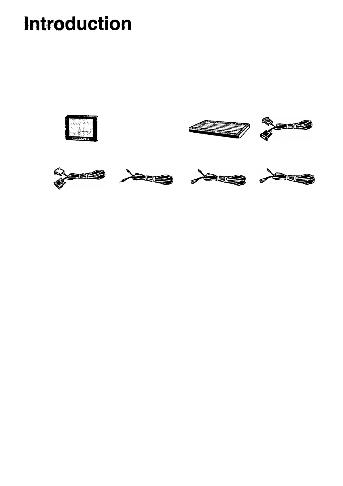
Thank you for purchasing the LCD Monitor for the Panasonic CF-17/M34 notebook computer series.
This LCD monitor features a touchscreen function, which makes computer operation possible by simply touching the surface of
the LCD monitor and pressing buttons - even when the computer is not being held.
^CD Monitor. Operating instructions.. 1
Serial Cable
Sound Cable
c.
Keyboard
PS/2 Cable
RGB Cable
Function Cable
7N
Page 5
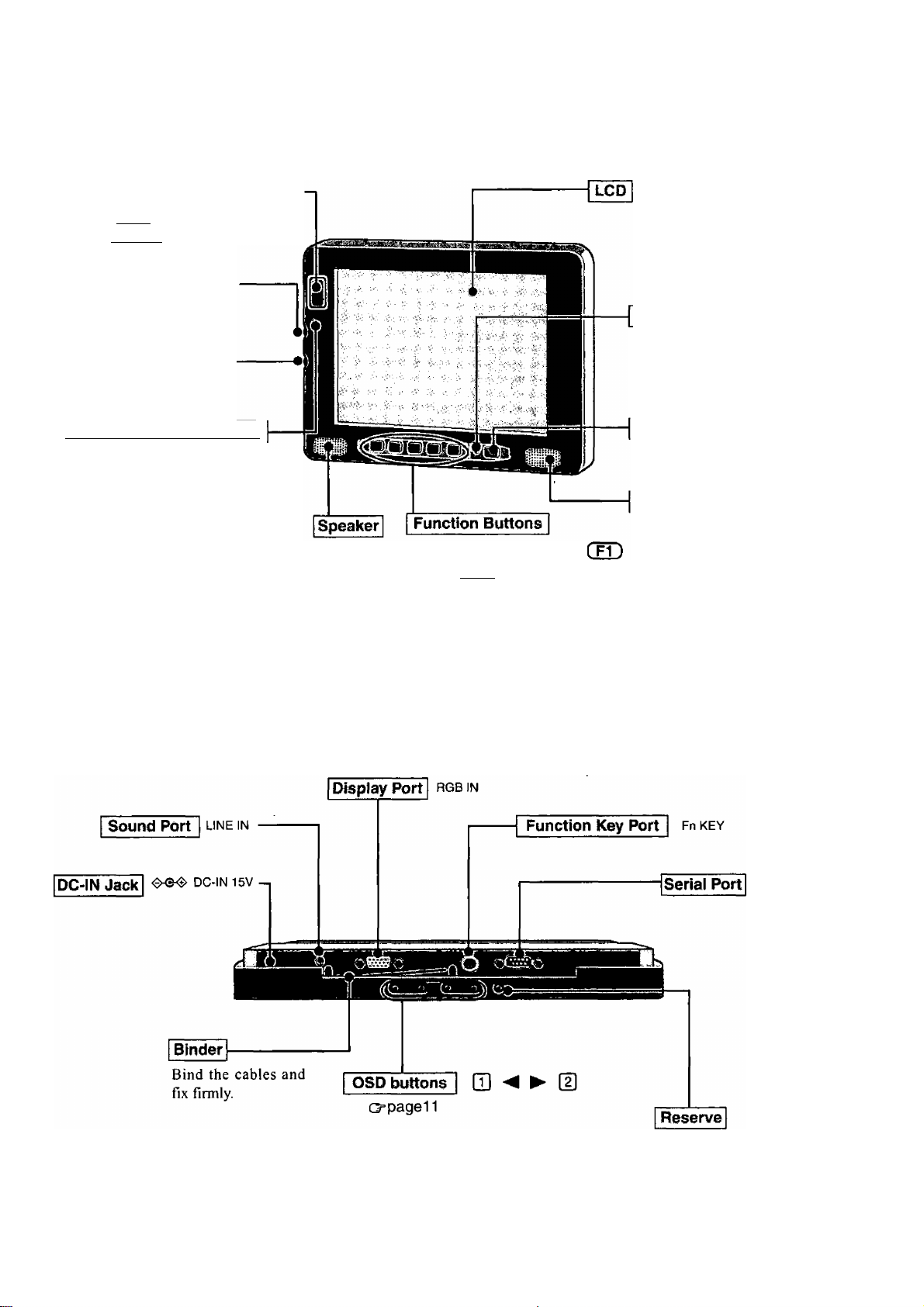
Names and Functions of Parts
<Front>
Emergency Button
The application software allo
cated to C F11 ) is started up.
Brightness Volume| (<>
C up
Q down
Speaker Volume 1 (“i ")
C up
Q down
Temperature tED Indicator
Green : Normal
The brightness can be ad
justed freely.
Orange : Drops the brightness auto-
matically due to an in
crease in the internal tem
perature.
Red ; The backlight goes OFF
automatically due to an in
crease in the internal tem
perature.
Does the same operation as ^
through ( F5 ) of the keyboard.
<Bottom>
LED Indicator
Green : power on
Orange : power on but no VGA Sig
nal or the cable is not con
nected.
Power Switch
0
Speaker
Do not have anyone except an
authorized repairperson push
this button.
Page 6

Mounting the LCD Monitor
y Connect your computer to the port replicator
(cooperating Instructions of the port replicator)
2 Remove the cover of the LCD Monitor
Remove the four screws, and remove the cover.
^ Connect the LCD Monitor to your computer (through the port replicator) and stand
alone keyboard via the connection cables (included)
<Rear View>
LCD Monitor
f1 Tn
------------------------
li LU-------------------------
Car Adapter if
(commercially available
product)
Car Adapter
(commercially available
product)
OCh
. .... Jj
DC-IN Jack H
=00
T T t T
Function Key Port
Serial Port
SERIAL l/F
Keyboard
c:—=3
DDDD_
ODOOD
Doma
DDOD
DDOa
anna
DDDD^
QDO
8
ODD
<Top View>
Fn KEY
01^
Headphone Jack I f)
Port Replicator
<Top View>
© RGB cable
© Serial cable
© Sound cable
@ PS/2 cable
© Function cable
Page 7

Attach the cover of the LCD Monitor
Attach the four screws.
5 Mount the LCD Monitor
Use these M4 screw holes to mount the LCD Monitor.
r
When installing the LCD monitor, locate the monitor under the dashboard as
shown in the figure to prevent the monitor from interrupting the sight of the
driver and to prevent the monitor from being hit by direct .sunlight.
Do not expose the computer to direct sunlight or excessive heat.
Page 8

Starting Up/Shutting Down
Starting Up
1 Turn the LCD Monitor on
Press the power switch.
2 Turn your computer on (cooperating Instructions of the computer)
3 Select your application
You are able to start working on your computer.
Shutting Down (power off your computer)
This procedure is shutting down without using the suspend or hibernation function.
(Q^ Reference Manual of the computer "Suspend/Hibemation Functions")
Display the shut down screen
After saving important data and closing each application, select [Shut Down] from the [Start] menu.
Confirm shut down
twiwHua tmwmrnmmwmm
Select [OK] after selecting [Shut down].
Your computer will power off automatically.
(In the OFF state, if you are not recharging your battery pack or if the pack is fully charged, your computer consumes approximately 1.5 W.)
«»mg!«
Select [OK] after selecting [Shut down the computer].
Your computer will power off automatically.
(In the OFF state, if you are not recharging your battery pack or if the pack is fully charged, your computer consumes approximately 1.5 W.)
Turn the LCD Monitor off
Press the power switch.
The LCD Monitor will not turn off until the computer is shut down completely.
8
Page 9

Touchscreen
The LCD Monitor is equipped with a touchscreen function allowing you to perform the same operations as the touch pad or mouse
by touching the surface of the display with your finger. (The operation settings can be changed in [Start] - [Programs] - [Updd] [Settings].)
Moving the cursor
Cursor
Double-clicking
Clicking
Dragging
Touch and hold the object (i. e.
file or icon), move your finger
on the surface (dragging the
object to the desired location),
then release your finger.
r
The touchscreen function can not be used in the MS-DOS mode and when using the full
screen in [MS-DOS prompt].
When the operation of panning (only LCD) is performed while the screen resolution is
set to [1024 X 768 dots] or more, the touchscreen function will not work properly.
If a change is made to the screen resolution, or the cursor can not be pointed correctly
with your finger, be sure to perform calibration in the [Start]-[PTograms]-[Updd]-[Cali
brate] menu.
rHandling-the-Touchscreen-|
Do not place any object on the surface or press down forcefully with sharp-pointed objects
(e.g., nails), hard objects that can leave marks (e.g., pencils and ball point pens).
Do not apply pressure within 5 mm of the perimeter of the display panel. The cursor may
move to the edge of the display.
Do not operate the computer when such things as dust are on the screen, or allow contact
with substances that could dirty the touchscreen, such as oil. The cursor may not work
properly in such cases.
When the touchscreen becomes dirty:
Use a dry soft cloth such as a gauze to clean the dirty areas.
Do not use benzene, thinner, or disinfectant- type alcohol.
Page 10

Touchscreen
rConfiguringtheTouchscreenn
When needed, the touchscreen can be configured using the following steps.
y Select from the taskbar or select [Settings] from [Start] - [Programs] - [Updd]
The following screen will appear.
—Calibration
Windows
Set the “double-click” set
tings.
Devices
Configure the device controller.
Hardware
Set the hardware resources.
Match this setting with the setting
for [Touchscreen] and [Serial Port
B] in the Setup Utility.
Settings
Set the general protocol
settings.
-----------------
TljiTiinmjitiw wi «t nsul
02 Pm« 2
Advanced
Set the advanced settings.
=1
At
Define the calibration setup.
Use when the cursor can not be pointed correctly with your
finger. (Needed if the alignment of the touchscreen with the
visual image change or adjust the display resolution).
Before you run the calibration, you need to set the device at
[Calibration settings for] as followings.
[Device I ] is for the computer
[Device2] is for the LCD Monitor
________
Status
Display the status of the controller.
■Ei
.About
Display the version number.
Button Modes
Set the button modes.
ir -AJd- -j
fr fîw
Caned [[[ oto;
- General
Set the general settings and functions.
Events
Set the events that can be generated by a
controller.
Xnote>
For more information, refer to [Help].
10
2 Make necessary changes
Click [OK]
NOTE^
Adjustments can be made when double-click operations are assumed by the computer although single-click opera
tions are intended, by clicking [Windows] from the display shown above and decreasing the value for [Time] in
[Double Click Settings].
It is also possible to change the double click speed for [Buttons] in [Start] - [Settings] - [Control Panel] - [Mouse]. It
is important to note that when the double click speed for [Mouse] is changed, the double click time for [Windows] is
also changed. However, the double click time for [Windows] and [Mouse] returns to its value before the change
when the computer is restarted.
Immediately run [Calibrate] when the number of points of calibration is changed.
Page 11

Adjusting the LCD Monitor
Fine adjustment on the display size, position, and so on, may be necessary since the signal timing differs depending on the com
puter.
7 Press Q]
The OSD main menu is displayed.
<OSD main menu>
lift=CJgpaWiTBri
9 •
ICON FUNCTION
Brightness
O'
Contrast
c
Color
[Ml
Position
+
Image
A
Auto Config
Miscellaneous
Information
□
DESCRIPTION
Adjust brightness of selected RGB channel
Adjust contrast of selected RGB channel
Set RGB color temperature
Move input image capture window
Adjust clock and phase
Automatically optimize the image quality
Miscellaneous settings
Display RGB input signal information
2 Select the icon by pressing ◄ or ► , then press (2]
• 0* (Brightness)
Brightness
[■
D (Contrast)
Contrast
32
90
The Brightness menu item is used to adjust the brightness of the selected RGB
channel. A slider indicating the current brightness value is displayed. The adjust
ment range is 0 to 63.
Adjust by pressing or ^ , then press [2]. (If you want to cancel, press Q])
The Contrast menu item is used to adjust the contrast of the selected RGB channel.
A slider indicates the current contrast value. The range of adjustment is 0 to 255.
Adjust by pressing or ^ , then press [2]. (If you want to cancel, press Q])
11
Page 12

Adjusting the LCD Monitor
um\ (Color)
Color
Auto Balance
RGB
Color Temperature
Select the item by pressing or ^ , then press
5 (Position)
The Color menu is used to adjust the brightness of Red, Green, Blue, or all color
channels.
<Auto Balance>
Select [|], the color is adjusted automatically.
<RGB>
The sub-menu is displayed.
Select the item by pressing or ^ , then press [2].
The sub-menu is displayed.
Adjust by pressing or ^ , then press . (If you want to cancel, press Q])
<Coior Temperature>
The sub-menu is displayed.
Select the item by pressing ^ or ^ , then press .
The sub-menu is displayed.
Adjust by pressing or ^ , then press . (If you want to cancel, press □ )
Position
The Position menu allows the adjustment of image position in Analog input mode.
H-Position
V-Position
Auto Center
Select the item by pressing or ^ , then press [2].
<H-Position>
H-position is used to adjust the horizontal image position manually. A slider and the
current value are displayed. The adjustment range is 0 to 127.
Adjust by pressing or ^ , then press [2]. (If you want to cancel, press Q] )
<V-Position>
V-position is used to adjust the vertical image position manually. A slider and the
current value are displayed. The maximum value for Vertical Position is to 0 to 47.
Adjust by pressing or ^ , then press [2]. (If you want to cancel, press Q] )
<Auto Center>
Select , the position is adjusted automatically.
^ (Image)
Image
The image menu allows the adjustment of ADC clock and phase in Analog input mode.
In Digital, Video, and S-Video input modes, clock and phase are fixed.
Phase
Clock
Auto Phase
12
Select the item by pressing ^ or ^ , then press [2].
Page 13

(Auto Configuration)
Auto Configuration
Yes No
(Miscellaneous)
Miscellaneous
INIT NVRam
OSD Timeout
OSD Position
<Phase>
Phase adjustment is used to adjust the ADC sample pixel clock. A slider and the current
value are displayed. The adjustment range is 0 to 31, representing 0-360 degrees.
Adjust by pressing or ^ , then press [2). (If you want to cancel, press [T])
<Clock>
Clock adjustment is used to adjust the number of clocks per line (samples per line). A
slider and the current value are displayed. The range of clock adjustment is +/- 30
pixels from the VESA standard.
Adjust by pressing or , then press . (If you want to cancel, press [T])
<Auto Phase>
Select [2], phase is adjusted automatically.
Auto Configuration automatically adjusts image position, clock, and phase. A confir
mation box is displayed to confirm the user selection. The default selection in the box
is “Yes”, highlighted by a green bar. If the “No” is selected, the main menu is re
opened and no changes are saved.
The Miscellaneous menu is used to select miscellaneous OSD setting and sub-menus.
Select the item by pressing or ^ , then press [2).
<INIT NVRam>
A confirmation box is displayed to confirm the user selection. The default selection is
“Yes”, and is highlighted by a green bar. If Q] is pressed, the previous menu is displayed.
<OSDTimeout>
OSD Timeout is used to set the OSD idle time-out. If no active action, key press or
automatic configuration occurs for the defined period, the OSD menu is closed. There
are four OSD time-out values available.
Seleet the item by pressing or ^ , then press .
<OSD Position>
The sub-menu is displayed.
Select the item by pressing or ^ , then press [2].
The sub-menu is displayed.
Adjust by pressing or ^ , then press . (If you want to cancel, press Q] )
□ (Information)
SYSTEM INFO
Version:
V-Freq-:
This menu is used to display information about the system. The OSD window is
displayed for 60 seconds after which control returns to main menu. If (T] is pressed,
the information window is closed and the main menu is displayed.
H-Freq-:
PixelCLK:
Width:
Height :
3 Press Q]
The OSD main menu disappears.
13
Page 14

Troubleshooting
When a problem occurs, refer to this page. If a problem appears to be related to a software application, read the software
related manual. If you still cannot troubleshoot the problem, contaet Panasonic Technical Support.
No display after powering
on
An afterimage appears (i.e.,
green, red, and blue dots
remain on the display) or
there are dots not display
ing the correct colors.
• Check the cable connection for the car adapter.
• Check the cable connection to the LCD Monitor.
• Check the brightness of the LCD Monitor.
• Has the computer been set to the power-saving mode?
To resume operation of your computer from the condition the power of the display is OFF
(for energy conservation purposes), press any key. (like C Ctrl ))
Set the power-saving mode to disable.
дтжта ДЛШШ»
Set [ECO Mode Timeout] and [Hibernation Timeout]/[Suspend Timeout] under [AC
Adapter Operation] to [Disable].
Set [System Standby] and [Turn off monitor] in [Start]-[Scttings]-[Control Pancl]-[Power
Management]-[Power Schemes] to [Never],
Set [Turn off monitor], [System Standby], and [System hibernates] in [Start]-[Settings]-
[Control Pancl]-[Powcr Options] to [Never],
• If the LCD of the computer is ON, press C Fn ) + C F3 ), and set [Display] in the Setup
Utility to [External Monitor] or [Simultaneous],
If an image is displayed for a prolonged period of time, an afterimage may appear. This is
not a malfunction. The afterimage will disappear when a different screen is displayed.
High-precision and advanced technologies arc necessary in the production of color liquid
crystal displays (color LCDs). Therefore, if 0.002% or less of the picture elements cither
fail to light or remain constantly lit (that is, more than 99.998% of elements are functioning
properly), no defect is considered to exist.
The sound is not heard
"Cable not connected" is
displayed
"Input Not Supported" is
displayed
Unable to input by touching
the display
The display is affected
The display no longer dis
plays properly
• Check the cable connection to the LCD Monitor,
• Check the volume setting of the computer.
Check the cable connection to the LCD Monitor.
The mode not supported is has been selected.
Set the display mode to 640 x 480 60 Hz or 800 x 600 60 Hz.
• Has the Setup Utility been used to set [Touchscreen] to [2E8/IRQ7] for the computer and
[Serial Port B] to [2F8/IRQ3] for the LCD Monitor?
• Confirm that the setting for resource in [Start]-[Programs]-[Updd]-[Settings]-[Hardware]
is [2E8/IRQ7] for the computer and [2F8/1RQ3]* for the LCD Monitor.
• Check the cable connection to the LCD Monitor.
*If the serial port A is used for LCD Monitor, set [3F8/1RQ4].
• The mode not supported has been selected.
Set the display mode to 640 x 480 60 Hz or 800 x 600 60 Hz.
• Check the cable connection to the LCD Monitor.
• The display appears distorted since the MS-DOS mode, XGA display, and refresh rates
over 60Hz arc not supported.
Select fErdJ from the OSD main menu, then select [INIT NVRam], then press .
Select “Yes”, then press [g]. Cépage 13
14
Page 15

Specifications
Model No. CF-VDL01
Input Interface Analog RGB Signal
LCD Type
Display Area 211.2 mm X 158.4 mm
Resolution
Color
Pixel Pitch 0.264 mm X 0.264 mm
Brightness 1000 cd/m"
Display Modes
Touchscreen
Interface Display Port Dsub 15-pin female
Speaker
DC-IN
Power Consumption
Physical Dimensions (W X H X D)
Weight
Environment
VGA
SVGA
Serial Port Dsub 9-pin male
Line IN
Function Key
Input
Temperature 5°Cto35°C {41 °Fto95°F}
Humidity
10.4 type
800 X 600 dots
256 K*’ (simulated 16.7 M)
640 X 480 60 Hz
800 X 600 60 Hz
Resistive
Miniature jack, 3.5 DIA
F1-F5, Emergency (F11)
Stereo Speaker (built in)
DC 15 V, 2.6 A‘"
40 W
280 mm X 224 mm X 30 mm {11.0 " X 8.8 " X 1.2 "}
Approx. 2.1 kg {4.6 lb.}
10 % to 90 % RH (No condensation)
” 1 K=1024
DC input Voltage Range 14.25 V-15.75 V
DC input Current 2.6 A or more.
- 15
Page 16

©2000 Matsushita Electric Industrial Co., LTD. All Rights Reserved.
Printed in Japan
FJ0800-0
DFQX5024ZA
liilllililllllllllilli
 Loading...