

Page 1
Battery Charger / Akkuladegerät /
Chargeur de Batterie / バッテリーチャージャー
Model No. / Modell-Nr. / Numéro de modèle / 品番
Printed in Japan
ENGLISH
DEUTSCH
FRANÇAIS
CF-VCBC11U
DFQW5425ZA SA0610-0
OPERATING INSTRUCTIONS
Introduction ....................................................2
Read Me First .................................................2
Precautions ....................................................9
Description of Parts/Connection ................10
Indicators .....................................................11
Charging the battery pack ..........................12
Specications ..............................................12
BEDIENUNGSANLEITUNG
Einführung ...................................................13
Read-Me-First-Dokument ............................ 13
Vorsichtsmaßnahmen .................................19
Beschreibung der Teile/Anschluss ............20
Betriebszustandsanzeigen .........................21
Laden des Akkupacks .................................22
Technische Daten ........................................22
INSTRUCTIONS D’UTILISATION
Introduction ..................................................23
Lecture préliminaire ....................................23
Précautions d’utilisation .............................29
Description des pièces de rechange/Connexion
Témoins ........................................................31
Chargement de la batterie ..........................32
Spécications ..............................................32
..30
E
D
F
日本語
保証書付き
● 取扱 説 明書 をよくお 読みのうえ 、正しく安
全にお使いください。
●
ご使用前に「安全上のご注意」( 39ページ)
を必ずお読みください。
● 保証 書 は「 お 買 い 上げ 日・販 売 店 名 」な ど
の記 入を 確かめ 、取扱 説明 書とともに大 切
に保管してください。
(日本国内向け)
取扱説明書
はじめに
..........................................................33
安全上のご注意
各部の名称/接続のしかた
状態表示ランプ
充電のしかた
仕様
................................................................44
保証とアフターサービス
................................................39
..................................41
................................................42
....................................................43
....................................44
J
Page 2
ENGLISH
Introduction
The battery charger is designed for charging the battery pack for the
Panasonic computer series. To recharge a battery pack, you will
need the AC adaptor and AC cord included with the computer. Read
both this Operating Instructions and the computer’s Operating
Instructions before using.
Read Me First
Information on Disposal for Users of Waste Electrical &
E
Electronic Equipment (private households)
This symbol on the products and/or accompanying
documents means that used electrical and electronic
products should not be mixed with general household
waste.
Please dispose of this item only in designated national
waste electronic collection schemes, and not in the
ordinary dust bin.
For business users in the European Union
If you wish to discard electrical and electronic equipment, please
contact your dealer or supplier for further information.
Information on Disposal in other Countries outside the
European Union
This symbol is only valid in the European Union.
If you wish to discard this product, please contact your local
authorities or dealer and ask for the correct method of disposal.
2
36-E-1
Page 3

< For U.S.A. >
Federal Communications Commission Radio Frequency Interference Statement
Note: This equipment has been tested and found to comply with the limits for a Class
B digital device, pursuant to Part 15 of the FCC Rules. These limits are designed to
provide reasonable protection against harmful interference in a residential installation.
This equipment generates, uses and can radiate radio frequency energy and, if not
installed and used in accordance with the instructions, may cause harmful interference
to radio communications. However, there is no guarantee that interference will not
occur in a particular installation. If this equipment does cause harmful interference to
radio or television reception, which can be determined by turning the equipment off
and on, the user is encouraged to try to correct the interference by one or more of the
following measures:
Reorient or relocate the receiving antenna.
•
Increase the separation between the equipment and receiver.
•
Connect the equipment into an outlet on a circuit different from that to which the
•
receiver is connected.
Consult the Panasonic Service Center or an experienced radio/TV technician for
•
help.
Warning
To assure continued compliance, use only shielded interface cables when connecting
to a computer or peripheral. Also, any changes or modications not expressly
approved by the party responsible for compliance could void the user’s authority to
operate this equipment.
This device complies with Part 15 of the FCC Rules.
Operation is subject to the following two conditions:
(1) This device may not cause harmful interference, and
(2) This device must accept any interference received, including interference that may
cause undesired operation.
This device is Class B veried to comply with Part 15 of FCC Rules when used with
Panasonic Notebook Computer.
E
Responsible Party: Panasonic Corporation of North America
One Panasonic Way
Secaucus, NJ 07094
Tel No:1-800-LAPTOP5 (1-800-527-8675)
6-M-1
< For Canada >
Canadian ICES-003
This Class B digital apparatus complies with Canadian ICES-003.
7-M-2
3
Page 4
Read Me First
Declaration of Conformity (DoC)
“Hereby, Panasonic Corporation declares that this
Battery Charger is in compliance with the essential
requirements and other relevant provisions of EU
Council Directives.”
Authorised Representative:
Panasonic Testing Centre
Panasonic Marketing Europe GmbH
Winsbergring 15, 22525 Hamburg, Germany
< EMC Requirement >
E
List of all cables and maximum length of the cable and other
ACCESSORIES
18-E-0
Name of the cable
and accessories
Maximum length
AC Cord 2 m*
AC Adaptor ——
1
Cable type or Model No. /
Reference page
AC cord ( Page 10)
CF-AA6502A /
CF-AA6503A ( Page 10)
*1 The AC cord length presents the usable and maximum length.
●
The use of accessories and cables other than those specied, with
the exception of cables sold by the manufacturer of this product as
replacement parts for internal components, may result in increased
emissions or decreased immunity of this product.
●
This product should not be used adjacent to or stacked with other
equipment and that if adjacent or stacked use is necessary, this
product should be observed to verify normal operation in the
conguration in which it will be used.
●
Portable and mobile RF communications equipment can affect this product.
●
This product has been tested and found to comply with the limits
for medical devices to the IEC60601-1-2: 2001 Electromagnetic
Compatibility standard.
These limits are designed to provide reasonable protection against
harmful interference in a typical installation. This product
generates, uses, and can radiate radio frequency energy and, if not
installed according with the instructions, may cause harmful
4
Page 5
interference to other devices in the vicinity. However, there is no
guarantee that interference will not occur in a particular installation.
If this product does cause harmful interference to other devices,
which can be determined by turning the equipment off and on, the
user is encouraged to try to correct the interference by one or more
of the following measures:
• Reorient or relocate the receiving device.
• Increase the separation distance between the equipment.
• Connect the equipment into an outlet on a circuit different from
that which the other device(s) are connected.
•
Consult the Panasonic Service Center or service technician for help.
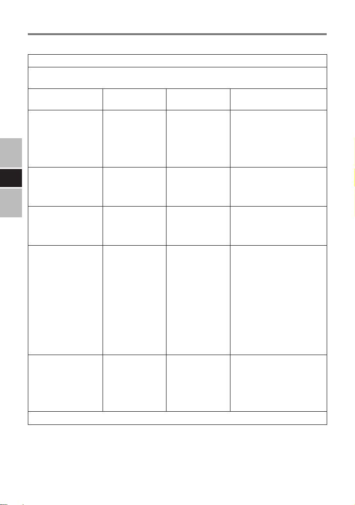
< Manufacture’s Declaration for EMC >
Table 1, Table 2, Table 3 and Table 4 describe the intended use
environment and EMC compliance levels of the system. For
maximum performance, ensure that the system is used in the
environments described in those tables.
The equipment is intended for use in the electromagnetic
environment specied in those tables.
Table 1
Guidance and manufacturer’s declaration-electromagnetic emissions
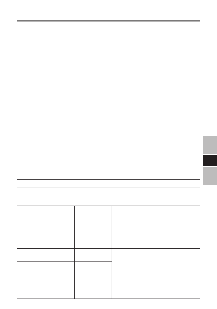
CF-VCBC11U is intended for use in the electromagnetic environment specied below. The
customer or user of the CF-VCBC11U should assure that is used in such an environment.
Emission test Compliance Electromagnetic environment-guidance
RF emissions
CISPR11
RF emissions
CISPR11
Harmonics emissions
IEC61000-3-2
Voltage uctuations/Flicker
emissions
IEC61000-3-3
Group 1
Class B
Not applicable
Complies
The CF-VCBC11U uses RF energy only for
its internal function. Therefore, its RF
emissions are very low and are not likely to
cause any interference in nearby electronic
equipment.
The CF-VCBC11U is suitable for use in all
establishments, including domestic
establishments and those directly connected
to the public low-voltage power supply
network that supplies buildings used for
domestic purposes.
E
5
Page 6
Read Me First
Table 2
Guidance and manufacturer’s declaration-electromagnetic immunity
CF-VCBC11U is intended for use in the electromagnetic environment specied below. The
customer or user of the CF-VCBC11U should assure that is used in such an environment.
Immunity test IEC60601 test
Electrostatic discharge
(ESD)
IEC61000-4-2
Electrical fast
E
transient/burst
IEC61000-4-4
Surge
IEC61000-4-5
Voltage Dips, short
interruptions and
voltage
variations on power
supply input lines
IEC61000-4-11
Power frequency
(50/60 Hz) magnetic
eld
IEC61000-4-8
NOTE UT is the A.C. mains voltage prior to application of the test level
level
±6 kV contact
±8 kV air
±2 kV for power
supply lines
±1 kV for input/
output lines
±1 kV differential
mode
±2 kV common
mode
< 5 % UT (> 95 %
dip in UT) for
0.5 cycle.
40 % UT (60 % dip
in UT) for 5 cycles.
70 % UT (30 % dip
in UT) for
25 cycles.
< 5 % UT (> 95 %
dip in UT) for
5 seconds.
3 A/m 3 A/m
Compliance level Electromagnetic
±6 kV contact
±8 kV air
±2 kV for power
supply lines
±1 kV differential
mode
±2 kV common
mode
< 5 % UT (> 95 %
dip in UT) for
0.5 cycle.
40 % UT (60 % dip
in UT) for 5 cycles.
70 % UT (30 % dip
in UT) for
25 cycles.
< 5 % UT (> 95 %
dip in UT) for
5 seconds.
environment-guidance
Floors should be wood
concrete or ceramic tile. If
oors are covered with
synthetic material, the relative
humidity should be at least
30 %.
Mains power quality should
be that of a typical
commercial or hospital
environment.
Mains power quality should
be that of a typical
commercial or hospital
environment.
Mains power quality should
be that of a typical
commercial or hospital
environment. If user of the
model CF-VCBC11U requires
continued operation during
power mains interruptions, it
is recommended that the
model CF-VCBC11U be
powered from an
uninterruptible power supply
or a battery.
Power frequency magnetic
elds should be at levels
characteristic of a typical
location in a typical
commercial or hospital
environment.
6
Page 7
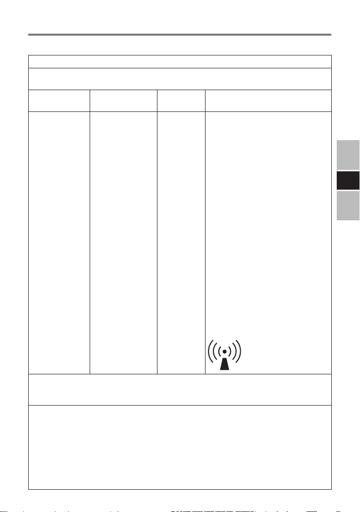
Table 3
Guidance and manufacturer’s declaration-electromagnetic immunity
CF-VCBC11U is intended for use in the electromagnetic environment specied below. The
customer or user of the CF-VCBC11U should assure that is used in such an environment.
Immunity test IEC60601 test
Conducted RF
IEC61000-4-6
Radiated RF
IEC61000-4-3
level
3 Vrms
150 kHz to 80 MHz
3 V/m
80 MHz to 2.5 GHz
Compliance
level
3 V
3 V/m
Electromagnetic environmentguidance
Portable and mobile RF
communications equipment should be
used no closer to any part of the Model
CF-VCBC11U, including cables, than
the recommended separation distance
calculated from the equation applicable
to the frequency of the transmitter.
Recommended separation distance:
d = 1.2√P
d = 1.2√P 80 MHz to 800 MHz
d = 2.3√P 800 MHz to 2.5 GHz
Where P is the maximum output power
rating of the transmitter in watts
according to the transmitter
manufacturer and d is the
recommended separation distance in
meters.
Field strengths from xed RF
transmitters, as determined by an
electromagnetic site survey *2, should
be less than the compliance level in
each frequency range. *
Interference may occur in the vicinity of
equipment marked with the following
symbol:
3
E
NOTE 1 At 80 MHz and 800 MHz, the higher frequency range applies.
NOTE 2 These guidelines may not apply in all situations. Electromagnetic propagation is
effected by absorption and reection from structures, objects and people.
*2 Field strengths from xed transmitters, such as base stations for radio (cellular / cordless)
telephones and land mobile radios, amateur radio, AM and FM radio broadcast and TV
broadcast cannot be predicted theoretically with accuracy. To assess the electromagnetic
environment due to xed RF transmitters, an electromagnetic site survey should be
considered. If the measured eld strength in the location in which the Model CF-VCBC11U is
used exceeds the applicable RF compliance level above, the Model CF-VCBC11U should be
observed to verify normal operation. If abnormal performance is observed, additional
measures may be necessary, such as re-orienting or relocating the Model CF-VCBC11U.
*3 Over the frequency range 150 kHz to 80 MHz, eld strengths should be less than 3 V/m.
7
Page 8
Read Me First
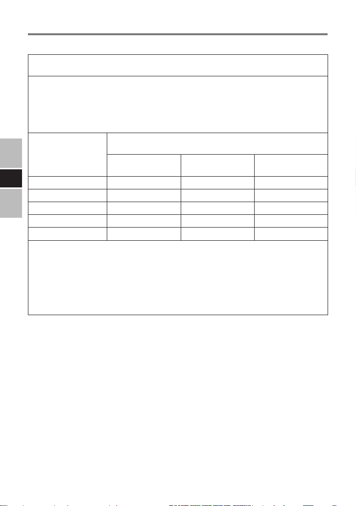
Table 4
Recommended Separation Distances Between Portable and Mobile RF Communications
Equipment and the CF-VCBC11U.
The Model CF-VCBC11U is intended for use in an electromagnetic environment in which
radiated RF disturbances are controlled. The customer or the user of the Model CF-VCBC11U
can help prevent electromagnetic interference by maintaining a minimum distance between
portable and mobile RF communications equipment (transmitters) and the Model CF-VCBC11U
as recommended below, according to the maximum output power of the communications
equipment.
Rated maximum
output power of
transmitter
(Watts)
E
0.01 0.12 0.12 0.23
0.1 0.38 0.38 0.73
1 1.2 1.2 2.3
10 3.8 3.8 7.3
100 12 12 23
For transmitters operating at a maximum output power not listed above, the recommended
separation distance d in meters can be estimated using the equation applicable to the frequency
of the transmitter, where P is the maximum output power rating of the transmitter in watts
according to the transmitter manufacturer.
NOTE 1 At 80 MHz and 800 MHz, the separation distance for the higher frequency range
applies.
NOTE 2 These guidelines may not apply in all situations. Electromagnetic propagation is
affected by absorption and reection from structures, objects and people.
Separation distance according to frequency of transmitter
(Meters)
150 kHz to 80 MHz
d = 1.2√P
80 MHz to 800 MHz
d = 1.2√P
800 MHz to 2.5 GHz
d = 2.3√P
8
Page 9
Precautions
●
UseThisChargertoChargeOnlytheSpeciedBatteryPack
(listed in the table below) and No Other
Electrolyte leakage, generation of heat or rupture may result.
●
UseOnlytheSpeciedACAdaptorWithThisBatteryCharger
Using an AC adaptor other than the one supplied (accessories and
designated optional products for models which support the battery
pack listed in the table below) may result in a re.
CAUTION
●
Install or remove the battery pack on a at stable surface.
●
Remove the battery before transporting the battery charger. The
battery pack may fall out while the charger is being carried.
●
Do not touch the battery charger connectors as it can damage or
transfer dust to the connectors and cause malfunction.
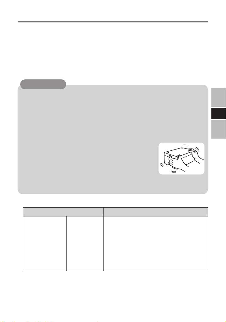
●
Refer to the “Operating Instructions” that came with the
computer for information on proper handling of the AC adaptor.
●
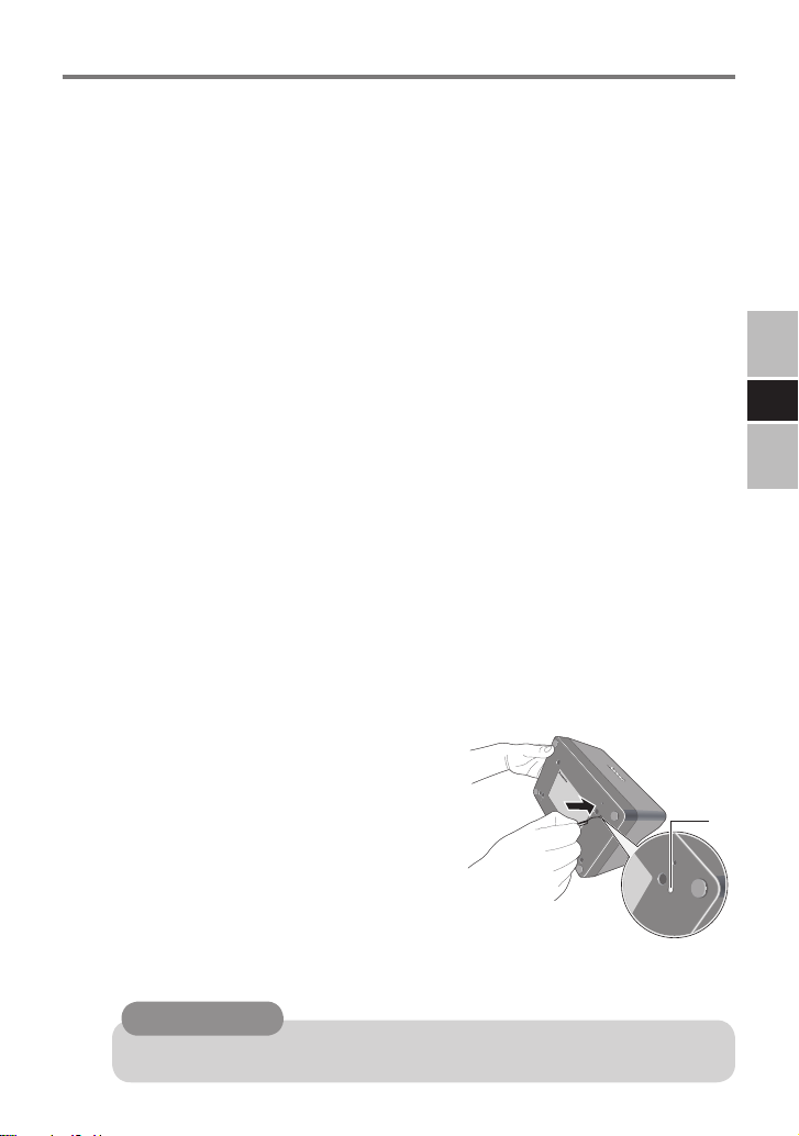
If dust or dirt has built up on the connectors,
disconnect the AC adaptor and battery pack,
turn the battery charger over, and remove the
dust and dirt. Dust buildup can cause faults
and prevent charging from being performed
successfully. Clean away dust regularly. Do not drop the battery
charger or subject it to heavy impacts.
E
●
Specied Battery Pack
Battery Pack Charging Time
CF-VZSU66U 1 battery:
Approx. 2.5 hours (Economy Mode
*1
(ECO) -Enabled:Approx. 4 hours)
2 batteries:
Approx. 3 hours (Economy Mode
(ECO) -Enabled:Approx. 4 hours)
3 batteries:
Approx. 4.5 hours (Economy Mode
(ECO) -Enabled:Approx. 7.5 hours)
4 batteries:
Approx. 5 hours (Economy Mode
(ECO) -Enabled:Approx. 7.5 hours)
*1
Set the Economy Mode (ECO) to Enable/Disable on the computer. The Economy
Mode (ECO) is set for the battery pack attached to the computer.
When the battery packs of the Economy Mode (ECO) having been set to Enable
and Disable are charged at the same time, the charging time may become longer.
The values in the brackets ( ) are the maximum charging times when the Economy
Mode (ECO) of all the battery packs is set to Enable.
9
Page 10

Description of Parts/Connection
Battery Charger
Power Indicator
DC IN 16V
DC-IN Jack
1 2 3 4
E
AC Adaptor
(CF-AA6503A / CF-AA6502A)
(The illustration above is CF-AA6503A.)
The CF-AA6502A AC adaptor is for use in Japan only.
Do not use outside of Japan.
Battery Indicator
AC Cord
Use the AC adaptor and AC cord supplied with the computer
(or ones sold separately as accessory).
10
Page 11
A
Indicators
●
The power indicator on the battery charger lights green when the
power is being supplied (when the adaptor is connected).
●
Battery indicator
Orange : Charging
Green : Fully-charged
Blinking red : Battery pack or charger may not be working
properly. Quickly remove the battery pack and
disconnect the AC adaptor, then connect them
again.
If the light continues to blink red, the battery
pack or charger may be faulty.
Blinking orange : Charging has been temporarily terminated as
the internal temperature of the battery pack is
outside the range possible for charging.
Charging will start automatically when the
temperature is restored to within this range.
Please wait.
Not lit : Battery pack is not properly inserted or charging
has not yet started (waiting to charge).
To check if the battery pack is properly inserted,
remove the battery pack to be checked and
attach it again. If the battery indicator blinks
several times after attaching, the battery pack
has been properly attached.
E
●
You can make the setting either to light
up the battery indicator or to ash it.
1. Connect the AC adaptor.
2. Remove the battery pack(s).
3. Turn the battery charger over.
4. Insert a pointed object (e.g., the
bent-out tip of a paper clip) into
the hole (A) and push it to the end
for several seconds.
Each time you push the hole, the setting switches between
lighting and
CAUTION
●
Do not use the pens supplied with the computer.
ashing
.
11
Page 12
Charging the battery pack
1 Connect the AC adaptor.
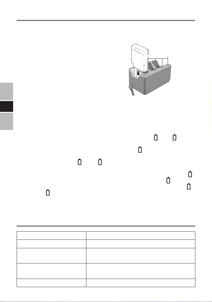
2 Insert the battery pack(s).
●
Four battery packs can be inserted
simultaneously. Each of them can
be inserted in any slot.
●
Be sure to insert the battery pack
as illustrated.
●
The battery indicator blinks
several times when the battery
pack is correctly inserted. If it
does not blink, insert the battery pack again.
●
E
Charging begins automatically.
●
If two or more battery packs are inserted, they are charged
two by two in the ascending order of the battery indicator
number (The battery packs will be charged two at a time.).
(Example 1) When four battery packs are connected:
The battery packs inserted to the battery indicators 1 and 2 are
charged. When either of the battery packs are fully-charged, the
battery pack inserted to the battery indicator 3 starts to be charged.
(Example 2) When the battery packs are connected to the
battery indicator 1 and 4:
Both battery packs will charge.
When the battery pack is connected to the battery indicator
2 midway, the battery pack for the battery indicator 4 will
stop charging. Then, the battery packs for battery indicator 1
and 2 will start to charge.
●
The battery pack or battery charger will become somewhat
warm during normal use. This is not a malfunction.
Battery Indicator
Specications
Input Voltage 16 V
Current Capacity 5.0 A
Operating Temperature/
Humidity
Dimensions
(W × H × D)
Weight Approx. 510 g {1.13 lb.}
12
5 °C to 35 °C {41 °F to 95 °F} /
30 % to 80 % RH (no condensation)
Approx. 190 mm × 92.5 mm × 116.5 mm
{7.5" × 3.6" × 4.6"}
Page 13
DEUTSCH
Einführung
Dieses Akkuladegerät ist zum Laden von Akkupacks für Computer
der Serie Panasonic vorgesehen. Zum Aukladen der Akkupacks
benötigen Sie neben dem Akkuladegerät den mit Ihrem Computer
gelieferten Netzadapter und Netzkabel.
Lesen Sie vor der Anwendung diese Bedienungsanleitung und die
Ihres PCs durch.
Read-Me-First-Dokument
Benutzerinformationen zur Entsorgung von elektrischen und
elektronischen Geräten (private Haushalte)
Entsprechend der grundlegenden Firmengrundsätzen der
Panasonic-Gruppe wurde ihr Produkt aus hochwertigen
Materialien und Komponenten entwickelt und hergestellt,
die recycelbar und wieder verwendbar sind.
Dieses Symbol auf Produkten und/oder begleitenden
Dokumenten bedeutet, dass elektrische und
elektronische Produkte am Ende ihrer Lebensdauer vom
Hausmüll getrennt entsorgt werden müssen.
Bringen Sie bitte diese Produkte für die Behandlung,
Rohstoffrückgewinnung und Recycling zu den eingerichteten
kommunalen Sammelstellen bzw. Wertstoffsammelhöfen, die diese
Geräte kostenlos entgegennehmen.
Die ordnungsgemäße Entsorgung dieses Produkts dient dem
Umweltschutz und verhindert mögliche schädliche Auswirkungen auf
Mensch und Umwelt, die sich aus einer unsachgemäßen Handhabung
der Geräte am Ende Ihrer Lebensdauer ergeben könnten.
Genauere Informationen zur nächstgelegenen Sammelstelle bzw.
Recyclinghof erhalten Sie bei Ihrer Gemeindeverwaltung.
Für Geschäftskunden in der Europäischen Union
Bitte treten Sie mit Ihrem Händler oder Lieferanten in Kontakt, wenn
Sie elektrische und elektronische Geräte entsorgen möchten. Er hält
weitere Informationen für sie bereit.
Informationen zur Entsorgung in Ländern außerhalb der
Europäischen Union
Dieses Symbol ist nur in der Europäischen Union gültig. Bitte treten
Sie mit Ihrer Gemeindeverwaltung oder Ihrem Händler in Kontakt,
wenn Sie dieses Produkt entsorgen möchten, und fragen Sie nach
einer Entsorgungsmöglichkeit.
36-G-1
D
13
Page 14
Read-Me-First-Dokument
Konformitätserklärung (DoC)
„Hiermit erklärt Panasonic Corporation, dass dieser
Akkuladegerät die wichtigsten Auagen und andere
relevante Bestimmungen der zutreffenden EU-
Direktiven erfüllt.“
Autorisierter Vertreter:
Panasonic Testing Centre
Panasonic Marketing Europe GmbH
Winsbergring 15, 22525 Hamburg, Bundesrepublik Deutschland
18-G-0
< EMV-Anforderungen >
Liste aller Kabel und maximale Kabellänge sowie anderes ZUBEHÖR
Bezeichnung von
Kabel und Zubehör
Netzkabel 2 m*
Maximale Länge
1
Netzteil ——
D
*1 Die Netzkabellänge nennt die verwendbare sowie die maximale Länge.
●
Die Verwendung von anderen als den angegebenen Zubehören
Kabeltyp oder Modellnummer /
Verweisseite
Netzkabel ( Seite 20)
CF-AA6502A /
CF-AA6503A ( Seite 20)
und Kabeln kann zu verstärkter Aussendung oder zu verminderter
Störfestigkeit diesem produkt führen. Als Ausnahme gelten die vom
Hersteller diesem produkt als Ersatzteile für innere Komponenten
vertriebenen Kabel.
●
Diesem produkt sollte nicht in unmittelbarer Nachbarschaft oder im Stapel
mit anderen Geräten betrieben werden. Wenn ein solcher Betrieb
erforderlich ist, muss beobachtet werden, ob diesem produkt in der
verwendeten Konguration bestimmungsgemäß funktioniert.
●
Diesem produkt kann von tragbaren und mobilen
Funkkommunikationsgeräten beeinträchtigt weden.
●
Diesem produkt wurde geprüft und entspricht den Grenzwerten für
medizinische Geräte gemäß der Norm IEC60601-1-2: 2001 zur
elektromagnetischen Verträglichkeit.
Diese Grenzwerte wurden festgelegt, um in typischen
Installationen angemessenen Schutz vor schädlichen
Störeinüssen zu gewährleisten. Diesem produkt erzeugt und
verwendet Hochfrequenzen und kann diese abstrahlen. Wenn es
nicht vorschriftsmäßig installiert wird, kann es schädliche
14
Page 15
Störungen an anderen Geräten in der Umgebung verursachen.
Es kann jedoch nicht ausgeschlossen werden, dass bei einer
bestimmten Installation Störungen auftreten. Wenn Diesem produkt
Störungen bei anderen Geräten verursacht – dies können Sie durch Einund Ausschalten des Gerätes feststellen – versuchen Sie, die Störungen
mit einer oder mehreren der folgenden Maßnahmen zu beheben:
• Richten Sie das Empfangsgerät neu aus, oder stellen Sie es an
einem anderen Ort auf.
• Vergrößern Sie die Entfernung zwischen dem Gerät und dem
Empfangsgerät.
• Schließen Sie das Gerät an eine Steckdose an, die von einem
anderen Stromkreis als das Empfangsgerät gespeist wird.
• Bitte wenden Sie sich an eine Panasonic-Kundendienststelle
oder einen Servicetechniker.
< Herstellererklärung zur EMV >
Tabelle 1, Tabelle 2, Tabelle 3 und Tabelle 4 beschreiben die geeignete
Betriebsumgebung und die Abstufungen der EMV-Konformität des Systems.
Für eine optimale Leistung muss sichergestellt sein, dass das System in der
entsprechenden Umgebung betrieben wird, die in den Tabellen angegeben ist.
Das Gerät ist für den Betrieb in den elektromagnetischen Umgebungen
ausgelegt, die in diesen Tabellen angegeben sind.
Tabelle 1
Elektromagnetische Ausstrahlungen – Leitlinien und Herstellererklärung
Das Modell CF-VCBC11U ist für den Betrieb in der unten angegebenen elektromagnetischen
Umgebung bestimmt. Der Kunde oder der Anwender des CF-VCBC11U sollte sicherstellen, dass
es in einer derartigen Umgebung betrieben wird.
Störaussendungsmessungen
HF-Aussendungen
CISPR11
HF-Aussendungen
CISPR11
Aussendungen von
Oberschwingungen
IEC61000-3-2
Aussendungen von
Spannungsschwankungen/ Flicker
IEC61000-3-3
Konformität Elektromagnetische Umgebung -
Gruppe 1
Klasse B
Nicht zutreffend
Konform
Leitfaden
Das CF-VCBC11U verwendet HF-Energie
ausschließlich für interne Funktionen. Daher
ist seine HF-Aussendung sehr gering, und es
ist unwahrscheinlich, dass benachbarte
elektronische Geräte gestört werden.
Das CF-VCBC11U ist für den Betrieb in allen
Einrichtungen einschließlich denen im
Wohnbereich geeignet, und solchen, die
unmittelbar an ein öffentliches
Niederspannungsnetz angeschlossen sind,
das auch Wohngebäude versorgt.
D
15
Page 16

Read-Me-First-Dokument
Tabelle 2
Elektromagnetische Störfestigkeit – Leitlinien und Herstellererklärung
Das CF-VCBC11U ist für den Betrieb in der unten angegebenen elektromagnetischen
Umgebung bestimmt. Der Kunde oder der Anwender des CF-VCBC11U sollte sicherstellen, dass
es in einer derartigen Umgebung betrieben wird.
Störfestigkeitsprüfungen
Entladung statischer
Elektrizität (ESD)
IEC61000-4-2
Schnelle transiente
elektrische
Störgrößen/Bursts
IEC61000-4-4
Stoßspannungen
(Surges)
IEC61000-4-5
D
Spannungseinbrüche,
Kurzzeitunterbrechungen
und Schwankungen der
Versorgungsspannung
IEC61000-4-11
Magnetfeld bei der
Versorgungsfrequenz
(50/60 Hz)
IEC61000-4-8
ANMERKUNG UT ist die Netzwechselspannung vor der Anwendung der Prüfpegel.
16
IEC60601
Prüfpegel
±6 kV
Kontaktentladung
±8 kV
Luftentladung
±2 kV für
Netzleitungen
± 1 kV für Eingangsund Ausgangsleitungen
±1 kV
Gegentaktspannung
±2 kV
Gleichtaktspannung
< 5 % UT (> 95 %
Einbruch der UT)
für ½ Periode.
40 % UT (60 %
Einbruch der UT)
für 5 Perioden.
70 % UT (30 %
Einbruch der UT)
für 25 Perioden.
< 5 % UT (> 95 %
Einbruch der UT)
für 5 Sekunden
3 A/m 3 A/m
Übereinstimmungspegel
±6 kV
Kontaktentladung
±8 kV
Luftentladung
±2 kV für
Netzleitungen
±1 kV
Gegentaktspannung
±2 kV
Gleichtaktspannung
< 5 % UT (> 95 %
Einbruch der UT)
für ½ Periode.
40 % UT (60 %
Einbruch der UT)
für 5 Perioden.
70 % UT (30 %
Einbruch der UT)
für 25 Perioden.
< 5 % UT (> 95 %
Einbruch der UT)
für 5 Sekunden
Elektromagnetische
Umgebung - Leitfaden
Fußböden sollten aus Holz,
Beton oder Keramikiesen
bestehen. Bei synthetischen
Bodenbelägen muss die
relative Luftfeuchtigkeit
mindestens 30 % betragen.
Die Qualität der
Versorgungsspannung sollte
der einer typischen Gewerbeoder Krankenhausumgebung
entsprechen.
Die Qualität der
Versorgungsspannung sollte
der einer typischen Gewerbeoder Krankenhausumgebung
entsprechen.
Die Qualität der
Versorgungsspannung sollte
der einer typischen Gewerbeoder Krankenhausumgebung
entsprechen. Wenn der
Anwender des CF-VCBC11U
auch beim Auftreten von
Unterbrechungen der
Energieversorgung einen
fortgesetzten Betrieb fordert,
wird empfohlen, das
CF-VCBC11U aus einer
unterbrechungsfreien
Stromversorgung oder einer
Batterie zu speisen.
Magnetfelder bei der
Netzfrequenz sollten den
typischen Werten, wie sie in
der Gewerbe- oder
Krankenhausumgebung
vorzunden sind, entsprechen.
Page 17

Tabelle 3
Elektromagnetische Störfestigkeit – Leitlinien und Herstellererklärung
Das Modell CF-VCBC11U ist für den Betrieb in der unten angegebenen elektromagnetischen
Umgebung bestimmt. Der Kunde oder der Anwender des CF-VCBC11U sollte sicherstellen, dass
es in einer derartigen Umgebung betrieben wird.
Störfestigkeitsprüfungen
Geleitete
HF-Störgrößen
IEC61000-4-6
Gestrahlte
HF-Störgrößen
IEC61000-4-3
IEC60601
Prüfpegel
3 Vrms
150 kHz bis 80 MHz
3 V/m
80 MHz bis 2,5 GHz
Übereinstimmungspegel
3V
3V/m
Elektromagnetische Umgebung Leitfaden
Tragbare und mobile Funkgeräte
sollten einschließlich der Leitungen in
keinem geringeren Abstand zum
CF-VCBC11U verwendet werden als
dem empfohlenen Schutzabstand, der
nach der für die Sendefrequenz
zutreffenden Gleichung berechnet wird.
Empfohlener Schutzabstand:
d = 1,2√P
d = 1,2√P für 80 MHz bis 800 MHz
d = 2,3√P für 800 MHz bis 2,5 GHz
Mit P als der Nennleistung des Senders in
Watt (W) gemäß Angaben des
Senderherstellers und d als empfohlenem
Schutzabstand in Metern (m).
Die Feldstärke stationärer Funksender
sollte bei allen Frequenzen gemäß einer
Untersuchung vor Ort *2 geringer als der
Übereinstimmungspegel sein. *
In der Umgebung von Geräten, die das
folgende Symbol tragen, sind
Störungen möglich:
3
D
ANMERKUNG 1 Bei 80 MHz und 800 MHz gilt der höhere Frequenzbereich.
ANMERKUNG 2 Diese Leitlinien sind möglicherweise nicht in allen Situationen anwendbar. Die
*2
Die Feldstärke stationärer Sender, wie z. B. Basisstationen von Funktelefonen (Handy/
Schnurlos) und mobilen Landfunkgeräten, Amateurfunkstationen, MW- und UKW-Rundfunk- und
Fernsehsendern kann theoretisch nicht genau vorherbestimmt werden. Um die
elektromagnetische Umgebung hinsichtlich der stationären HF-Sender zu bewerten, sollte eine
Standortuntersuchung erwogen werden. Wenn die gemessene Feldstärke an dem Standort, an
dem das Modell CF-VCBC11U benutzt wird, die obigen Übereinstimmungspegel überschreitet,
muss beobachtet werden, ob das Modell CF-VCBC11U normal funktioniert. Wenn ungewöhnliche
Leistungsmerkmale beobachtet werden, können zusätzliche Maßnahmen erforderlich sein, wie z.
B. eine veränderte Ausrichtung oder ein anderer Standort des CF-VCBC11U.
*3
Über den Frequenzbereich von 150 kHz bis 80 MHz sollte die Feldstärke geringer als 3 V/m sein.
Ausbreitung elektromagnetischer Größen wird durch Absorptionen und
Reexionen der Gebäude, Gegenstände und Menschen beeinusst.
17
Page 18

Read-Me-First-Dokument
Tabelle 4
Empfohlene Schutzabstände zwischen tragbaren und mobilen
HF-Telekommunikationsgeräten und dem CF-VCBC11U.
Das Modell CF-VCBC11U ist für den Betrieb in einer elektromagnetischen Umgebung bestimmt,
in der die HF-Störgrößen kontrolliert sind. Der Kunde oder der Anwender des CF-VCBC11U kann
helfen, elektromagnetische Störungen zu vermeiden, indem er den Mindestabstand zwischen
tragbaren und mobilen HF-Telekommunikationsgeräten (Sendern) und dem CF-VCBC11U – je
nach Ausgangsleistung des Kommunikationsgerätes, wie unten angegeben – einhält.
Maximale NennAusgangsleistung des
Senders
(Watt)
0.01 0.12 0.12 0.23
0.1 0.38 0.38 0.73
1 1.2 1.2 2.3
10 3.8 3.8 7.3
100 12 12 23
Für Sender, deren maximale Nennleistung in obiger Tabelle nicht angegeben ist, kann der
empfohlene Schutzabstand d in Metern (m) unter Verwendung der Gleichung für die jeweilige
Frequenz ermittelt werden, wobei P die maximale Nennleistung des Senders in Watt (W) gemäß
Angabe des Senderherstellers ist.
D
ANMERKUNG 1 Bei 80 MHz und 800 MHz gilt der Schutzabstand des höheren
ANMERKUNG 2 Diese Leitlinien sind möglicherweise nicht in allen Situationen anwendbar. Die
Schutzabstand abhängig von der Sendefrequenz (Meter)
150 kHz bis 80 MHz
d = 1,2√P
Frequenzbereichs.
Ausbreitung elektromagnetischer Größen wird durch Absorptionen und
Reexionen der Gebäude, Gegenstände und Menschen beeinusst.
80 MHz bis 800 MHz
d = 1,2√P
800 MHz bis 2,5 GHz
d = 2,3√P
18
Page 19

Vorsichtsmaßnahmen
●
Verwenden Sie das Ladegerät ausschließlich zum Laden des angegebenen
Akkupacks (das in der untenstehenden Tabelle aufgelistet ist)
Es kann zum Austreten der Elektrolytüssigkeit, zu Erwärmung
oder Platzen kommen.
●
Verwenden Sie nur das angegebene Netzteil für dieses Akkuladegerät
Die Verwendung eines anderen Netzteils als des mitgelieferten
(Zubehörteile und designierte Sonderprodukte für die Modelle, die
Akkupack unterstützen, sind in der untenstehenden Tabelle
aufgelistet) kann zu einem Brand führen.
VORSICHT
●
Beim Einsetzen und Entfernen des Akkupacks muss das
Akkuladegerät auf einer ebenen, stabilen Unterlage aufgestellt sein.
●
Entfernen Sie vor einem Transport des Akkuladegerätes das
Akkupack. Anderenfalls kann das Akkupack beim Tragen aus
dem Akkuladegerät herausfallen.
●
Fassen Sie die Klemmen des Batterieladegeräts nicht an, das
sie anderenfalls beschädigt werden können bzw. sich Staub
darauf absetzen und zu einer Funktionsstörung führen kann.
●
Informationen über die korrekte Handhabung des Netzadapters
nden Sie in der Bedienungsanleitung Ihres Computers.
●
Falls sich Staub oder Schmutz auf den Klemmen gebildet hat, trennen Sie den
Netzadapter und das Akkupack, drehen Sie das
Akkuladegerät um und entfernen Sie den Staub oder
Schmutz. Staubbildung kann zu Störungen führen und
einen erfolgreichen Ladevorgang verhindern. Entfernen
Sie den Staub regelmäßig. Lassen Sie das Akkuladegerät
nicht fallen und setzen Sie es keinen starken Stößen aus.
D
●
Unterstützte Akkupack
Akkupack Ladezeit
CF-VZSU66U 1 Akku:
2 Akkus:
3 Akkus:
4 Akkus:
*1
Stellen Sie den Economy Mode (ECO) am Computer auf Aktiviert/Deaktiviert. Der
Economy Mode (ECO) ist für das daran angeschlossene Akkupack eingestellt.
Wenn im Economy Mode (ECO) auf Aktivieren und Deaktivieren gestellte
Akkupacks gleichzeitig aufgeladen werden, kann sich die Ladezeit erhöhen.
Die Werte in Klammern ( ) sind die maximalen Ladezeiten, wenn der Economy
Mode (ECO) aller Batterien auf Aktivieren eingestellt ist.
Ca. 2,5 Std. (Economy Mode (ECO) -Aktiviert:Ca.4 Std.)
Ca. 3 Std. (Economy Mode (ECO) -Aktiviert:Ca.4 Std.)
Ca. 4,5 Std. (Economy Mode (ECO) -Aktiviert:Ca.7,5 Std.)
Ca. 5 Std. (Economy Mode (ECO) -Aktiviert:Ca.7,5 Std.)
*1
19
Page 20

Beschreibung der Teile/Anschluss
Akkuladegerät
Betriebsanzeige
DC IN 16V
GleichstromEingangsbuchse
1 2 3 4
AkkuStatusanzeigelampe
Netzadapter
(CF-AA6503A / CF-AA6502A)
(Die abbildung oben ist CF-AA6503A.)
D
Der Netzadapter CF-AA6502A ist nur für den Gebrauch in
Japan vorgesehen. Nicht außerhalb Japans verwenden.
Netzkabel
Verwenden Sie den Netzadapter und das Netzkabel, die mit
dem Computer mitgeliefert wurden (oder separat als Zubehör
verkaufte).
20
Page 21

A
Betriebszustandsanzeigen
●
Die Betriebsanzeige am Akkuladegerät leuchtet grün, sobald das
Gerät mit Strom versorgt wird (bei Anschluss des Adapters).
●
Akku-Statusanzeigelampe
Orangefarben : Ladevorgang ndet statt.
Grün : Akkupack ist vollständig aufgeladen.
Blinkt rot :
Blinkt
orangefarben :
Leuchtet nicht : Das Akkupack wurde nicht richtig eingesetzt
Das Akkupack oder das Ladegerät funktioniert
möglicherweise nicht richtig. Entfernen Sie sofort
das Akkupack und trennen Sie den Netzadapter
und schließen Sie beide wieder an.
Blinkt die Lampe weiterhin rot, ist das Akkupack
oder das Ladegerät möglicherweise defekt.
Der Ladevorgang wurde vorübergehend
abgebrochen, weil die Innentemperatur des
Akkupacks außerhalb des für den Ladevorgang
zulässigen Bereichs liegt. Der Ladevorgang wird
automatisch fortgesetzt, sobald die Temperatur
wieder im zulässigen Bereich liegt. Bitte warten.
oder der Ladevorgang hat noch nicht begonnen
(Warten auf Ladebeginn).
Um zu prüfen, ob das Akkupack richtig
eingesetzt wurde, nehmen Sie das Akkupack
heraus, überprüfen Sie es und setzen Sie es
wieder ein. Blinkt die Akku-Statusanzeigelampe
nach dem Einsetzen mehrmals, wurde das
Akkupack richtig eingesetzt.
D
●
Sie können die Akku-Statusanzeigelampe
wahlweise leuchtend oder blinkend einstellen.
1.
Schließen Sie den Netzadapter an.
2.
Entfernen Sie das/die Akkupack(s).
3.
Drehen Sie das Akkuladegerät um.
4.
Führen Sie einen spitzen Gegenstand
(z. B. die nach außen gebogene Spitze
einer Büroklammer) in die Öffnung (A)
ein und drücken Sie sie mehrere Sekunden so weit wie möglich hinein.
Bei jedem Drücken in die Öffnung schaltet die Einstellung zwischen
Leuchten und Blinken hin und her.
VORSICHT
●
Verwenden Sie nicht die mit dem Computer mitgelieferten Stifte.
21
Page 22

Laden des Akkupacks
1 Schließen Sie den Netzadapter an.
D
2
Einsetzen des (der) Akkupacks.
●
Vier Akkupacks können gleichzeitig
eingesetzt werden. Jedes Akkupack
kann in jeden Schlitz eingesetzt werden.
●
Achten Sie darauf, das Akkupack
wie gezeigt einzuführen.
●
Die Akku-Statusanzeigelampe blinkt
mehrmals, wenn das Akkupack richtig
angeschlossen ist. Blinkt sie nicht,
schließen Sie das Akkupack erneut an.
●
Der Ladevorgang beginnt automatisch.
●
Falls zwei oder mehr Akkupacks angeschlossen sind, werden sie in
absteigender Reihenfolge der Akku-Statusanzeigelampennummer jeweils
zu zweit aufgeladen (es werden jeweils zwei Akkus auf einmal aufgeladen).
(Beispiel 1) Wenn vier Akkupacks angeschlossen sind:
Werden die Akkupacks aufgeladen, die mit den AkkuStatusanzeigelampen 1 und 2 verbunden sind. Wenn eines der
Akkupacks vollständig aufgeladen ist, beginnt das Auaden des
Akkupacks, das mit der Akku-Statusanzeigelampe 3 verbunden ist.
(Beispiel 2) Wenn Akkupacks an der Akku-Statusanzeigelampe 1
und 4 angeschlossen sind:
Beide Akkupacks werden aufgeladen.
Wenn während des Auadens ein Akkupack an die Akku-
Statusanzeigelampe 2 angeschlossen wird, wird das Auaden des
an die Akku-Statusanzeigelampe 4 angeschlossenen Akkupacks
eingestellt. Anschließend beginnt das Auaden der Akkupacks der
Akku-Statusanzeigelampen 1 und 2.
●
Das Akkupack oder Ladegerät erwärmt sich bei normalem
Einsatz. Dies ist keine Fehlfunktion.
AkkuStatusanzeigelampe
Technische Daten
Eingangsspannung 16 V
Leistung Saufnahme 5,0 A
Betriebstemperatur/-
luftfeuchtigkeit
Abmessungen (B × H × T)
Gewicht Ca. 510 g
22
5 °C bis 35 °C / 30 % bis 80 % relative
Luftfeuchtigkeit (nicht Kondensierend)
Ca. 190 mm × 92,5 mm × 116,5 mm
Page 23

FRANÇAIS
Introduction
Le chargeur de batterie est conçu pour recharger les batteries des
ordinateurs Panasonic. Pour recharger la batterie vous aurez besoin
de l’adaptateur secteur et du cordon d’alimentation livrés avec
l’ordinateur.
Lisez le présent instructions d’utilisation et le instructions d’utilisation
de l’ordinateur avant toute utilisation.
Lecture préliminaire
Informations relatives à l’évacuation des déchets, destinées aux
utilisateurs d’appareils électriques et électroniques (appareils
ménagers domestiques)
Lorsque ce symbole gure sur les produits et/ou les
documents qui les accompagnent, cela signie que les
appareils électriques et électroniques ne doivent pas
être jetés avec les ordures ménagères.
Pour que ces produits subissent un traitement, une récupération et
un recyclage appropriés, envoyez-les dans les points de collecte
désignés, où ils peuvent être déposés gratuitement.
Dans certains pays, il est possible de renvoyer les produits au
revendeur local en cas d’achat d’un produit équivalent.
En éliminant correctement ce produit, vous contribuerez à la
conservation des ressources vitales et à la prévention des éventuels
effets négatifs sur l’environnement et la santé humaine qui pourraient
survenir dans le cas contraire.
An de connaître le point de collecte le plus proche, veuillez
contacter vos autorités locales.
Des sanctions peuvent être appliquées en cas d’élimination
incorrecte de ces déchets, conformément à la législation nationale.
Utilisateurs professionnels de l’Union européenne
Pour en savoir plus sur l’élimination des appareils électriques et
électroniques, contactez votre revendeur ou fournisseur.
Informations sur l’évacuation des déchets dans les pays ne
faisant pas partie de l’Union européenne
Ce symbole n’est reconnu que dans l’Union européenne. Pour
supprimer ce produit, contactez les autorités locales ou votre
revendeur an de connaître la procédure d’élimination à suivre.
36-F-1
F
23
Page 24

Lecture préliminaire
Déclaration de conformité (DoC)
“Panasonic Corporation déclare par la présente que ce
Chargeur de batterie est conforme aux exigences
fondamentales et autres dispositions pertinentes
prévues par les Directives du Conseil de l’UE.”
Représentant agréé:
Panasonic Testing Centre
Panasonic Marketing Europe GmbH
Winsbergring 15, 22525 Hambourg, Allemagne
18-F-0
< Exigences CME >
Liste des câbles, longueur maximum de câble et autres ACCESSOIRES
Nom du câble et
accessoires
Cordon d’alimentation
secteur
Adaptateur secteur ——
*1 La longueur du cordon d’alimentation présente la longueur utilisable maximale.
●
L’utilisation d’accessoires et de câbles différents de ceux spéciés, à
l’exception des câbles vendus par le fabricant ce produit, comme
pièce de rechange pour les composants internes, peut entraîner une
augmentation des émissions ou une baisse de l’immunité ce produit.
●
Ce produit ne doit pas être utilisé à côté ou au-dessus d’autres
équipements. Si un tel usage est nécessaire, il faudra vérier que dans sa
F
conguration d’utilisation ce produit fonctionne normalement.
●
L’équipement de communications RF portable et mobile peut
affecter ce produit.
●
Ce produit a été testé et déclaré conforme aux limites imposées
aux appareils médicaux conformément à la norme IEC60601-1-2 :
2001 sur la compatibilité électromagnétique.
Ces normes sont destinées à assurer une protection raisonnable
contre les interférences nuisibles, lorsque le matériel est utilisé dans
une installation type. Ce produit produit, utilise et peut émettre de
l’énergie sous forme de fréquences radio, et peut, s’il n’est pas
installé et utilisé conformément aux consignes d’utilisation, provoquer
des interférences avec d’autres appareils situés à proximité.
24
Longueur
maximum
1
2 m*
Type de câble ou n° de
modèle / Page de référence
Cordon secteur
( Page 30)
CF-AA6502A /
CF-AA6503A ( Page 30)
Page 25

Cependant, nous ne pouvons garantir l’absence totale d’interférence
dans une installation donnée. Si ce produit devait provoquer des
interférences nuisibles avec d’autres appareils, ce qu’il est facile de
déceler en éteignant puis en rallumant cet équipement, il est alors
vivement conseillé à l’utilisateur d’essayer de supprimer ces
interférences en prenant une ou plusieurs des mesures suivantes:
• Réorienter ou repositionner le dispositif de réception.
• Augmenter la distance de séparation avec l’équipement.
• Brancher l’équipement sur la prise d’un circuit autre que celui sur
lequel est branché le ou les appareils.
• Consulter le Centre de service Panasonic ou le technicien de
réparation pour obtenir de l’aide.
< Déclaration du fabricant - CME >
Les tableaux 1, 2, 3 et 4 décrivent l’environnement d’utilisation prévu
et les niveaux de conformité CME du système. Pour des
performances maximum, assurez-vous que le système est utilisé
dans les environnements décrits dans ces tableaux.
Cet équipement est prévu pour être utilisé dans l’environnement
électromagnétique spécié dans ces tableaux.
Tableau 1
Conseils et déclaration du fabricant – émissions électromagnétiques
Le CF-VCBC11U est prévu pour être utilisé dans l’environnement électromagnétique indiqué
ci-dessous. Le client ou l’utilisateur du CF-VCBC11U doit s’assurer qu’il est utilisé dans cet
environnement.
Test d’émission Conformité Environnement électromagnétique -
Émissions RF
CISPR11
Émissions RF
CISPR11
Émissions d’harmoniques
IEC61000-3-2
Fluctuations de tension/
Émissions de icker
IEC61000-3-3
Groupe 1
Classe B
Non applicable
Conforme
conseils
Le CF-VCBC11U utilise de l’énergie RF
uniquement pour son fonctionnement interne.
Aussi, ses émissions RF sont très basses et
ne sauraient provoquer d’interférences avec
l’équipement situé à proximité.
Le CF-VCBC11U est adapté à une utilisation
dans tous les locaux, notamment les locaux
privés et ceux directement connectés au
réseau électrique public basse tension qui
équipe les immeubles destinés à un usage
privé.
F
25
Page 26

Lecture préliminaire
Tableau 2
Conseils et déclaration du fabricant – immunité électromagnétique
Le CF-VCBC11U est prévu pour être utilisé dans l’environnement électromagnétique indiqué
ci-dessous. Le client ou l’utilisateur du CF-VCBC11U doit s’assurer qu’il est utilisé dans cet
environnement.
Test d’immunité Niveau de test
Décharge
électrostatique
IEC61000-4-2
Courant électrique
transitoire rapide/salve
IEC61000-4-4
Surtension
IEC61000-4-5
Baisses de tension,
brèves interruptions et
variations de tension
sur les lignes
d’alimentation
électrique
IEC61000-4-11
F
Champ magnétique de
la fréquence
d’alimentation
(50/60 Hz)
IEC61000-4-8
REMARQUE UT correspond à la tension secteur CA avant l’application du niveau test
IEC60601
Contact ±6 kV
Air ±8 kV
±2 kV pour les
lignes
d’alimentation
électrique
±1 kV pour les
lignes d’entrée/
sortie
±1 kV mode
différentiel
±2 kV mode
commun
< 5 % UT (> 95 %
baisse en UT) pour
0,5 cycle.
40 % UT (60 %
baisse en UT) pour
5 cycles.
70 % UT (30 %
baisse en UT) pour
25 cycles.
< 5 % UT (> 95 %
baisse en UT) pour
5 secondes.
3 A/m 3 A/m Les champs magnétiques de
26
Niveau de
conformité
Contact ±6 kV
Air ±8 kV
±2 kV pour les
lignes
d’alimentation
électrique
±1 kV mode
différentiel
±2 kV mode
commun
< 5 % UT (> 95 %
baisse en UT) pour
0,5 cycle.
40 % UT (60 %
baisse en UT) pour
5 cycles.
70 % UT (30 %
baisse en UT) pour
25 cycles.
< 5 % UT (> 95 %
baisse en UT) pour
5 secondes.
Environnement
électromagnétique - conseils
Le sol doit être en bois, en
béton ou en carreaux de
céramique. Si les sols sont
recouverts de matériau
synthétique, l’humidité relative
doit être d’au moins 30 %.
La qualité du réseau secteur
doit être la qualité type pour
un environnement commercial
ou hospitalier.
La qualité du réseau secteur
doit être la qualité type pour
un environnement commercial
ou hospitalier.
La qualité du réseau secteur
doit être la qualité type pour
un environnement commercial
ou hospitalier. Si l’utilisateur
du modèle CF-VCBC11U
exige un fonctionnement
continu pendant les
interruptions de courant
secteur, il est conseillé
d’alimenter le modèle
CF-VCBC11U à partir d’une
alimentation sans coupure ou
d’une batterie.
fréquences d’alimentation
doivent être à des niveaux
caractéristiques d’un site type
dans un environnement
commercial ou hospitalier
type.
Page 27

Tableau 3
Conseils et déclaration du fabricant – immunité électromagnétique
Le CF-VCBC11U est prévu pour être utilisé dans l’environnement électromagnétique indiqué ci-dessous.
Le client ou l’utilisateur du CF-VCBC11U doit s’assurer qu’il est utilisé dans cet environnement.
Test d’immunité Niveau de test
RF par
conduction
IEC61000-4-6
RF par
rayonnement
IEC61000-4-3
IEC60601
3 Vrms
150 kHz à 80 MHz
3 V/m
80 MHz à 2,5 GHz
Niveau de
conformité
3 V
3 V/m
Environnement électromagnétique conseils
L’équipement de communications RF
portable et mobile ne doit pas être utilisé
à une distance inférieure à la distance de
séparation conseillée par rapport à
n’importe quelle pièce du modèle
CF-VCBC11U, y les câbles, distance
calculée à l’aide de l’équation applicable
à la fréquence du transmetteur.
Distance de séparation conseillée:
d = 1,2√P
d = 1,2√P 80 à 800 MHz
d = 2,3√P 800 MHz à 2,5 GHz
Où P est la puissance nominale
maximum du transmetteur en watts selon
le fabricant de l’émetteur et d la distance
de séparation conseillée en mètres.
Les intensités de champs provenant
d’émetteurs RF xes déterminées par une
étude de site électromagnétique *2, doivent
être inférieures au niveau de conformité
pour chaque plage de fréquences. *
L’interférence peut se produire à
proximité de l’équipement estampillé
du symbole suivant:
3
REMARQUE 1 A 80 et 800 MHz, la plage de fréquences élevées s’applique.
REMARQUE 2
*2 Les intensités de champs provenant d’émetteurs xes, tels que les stations de base pour
téléphones radio (portables / sans l) et radios mobiles terrestres, radios amateur,
radiodiffusion AM et FM et diffusion TV ne peuvent pas être prédites théoriquement avec
précision. Pour évaluer l’environnement électromagnétique dû aux émetteurs RF xes, une
étude de site électromagnétique doit être envisagée. Si l’intensité de champ mesurée sur le
site où le modèle CF-VCBC11U est utilisé dépasse le niveau de conformité RF applicable
ci-dessus, il est nécessaire de vérier le fonctionnement normal du modèle CF-VCBC11U. Si
des performances anormales sont observées, des mesures supplémentaires peuvent s’avérer
nécessaires, par exemple la réorientation ou le repositionnement du modèle CF-VCBC11U.
*3 Au-delà de la plage de fréquences 150 kHz à 80 MHz, les intensités de champs doivent être
inférieures à 3 V/m.
Ces conseils ne s’appliquent pas à toutes les situations. La propagation électromagnétique
est affectée par l’absorption et la réexion des structures, objets et personnes.
F
27
Page 28

Lecture préliminaire
Tableau 4
Distances de séparation conseillées entre l’équipement de communications RF portable
et mobile et le CF-VCBC11U.
Le modèle CF-VCBC11U est prévu pour être utilisé dans un environnement électromagnétique
dans lequel les perturbations RF de rayonnement sont contrôlées. Le client ou l’utilisateur du
modèle CF-VCBC11U peut aider à empêcher les interférences électromagnétiques en
maintenant une distance minimum entre l’équipement de communications RF portable et mobile
(émetteurs) et le modèle CF-VCBC11U comme cela est conseillé ci-dessous, en fonction de la
puissance nominale maximum de l’équipement de communications.
Puissance nominale
maximum de
l’émetteur
(en watts)
0.01 0.12 0.12 0.23
0.1 0.38 0.38 0.73
1 1.2 1.2 2.3
10 3.8 3.8 7.3
100 12 12 23
Pour les émetteurs qui fonctionnent avec une puissance nominale maximum non répertoriée
ci-dessus, la distance de séparation conseillée
l’équation applicable à la fréquence de l’émetteur, où P est la puissance nominale maximum de
l’émetteur en watts selon le fabricant de l’émetteur.
REMARQUE 1 A 80 et 800 MHz, la distance de séparation de la plage de fréquences élevées
s’applique.
REMARQUE 2 Ces conseils ne s’appliquent pas à toutes les situations. La propagation
électromagnétique est affectée par l’absorption et la réexion des structures,
objets et personnes.
Distance de séparation selon la fréquence de l’émetteur (en
mètres)
150 kHz à 80 MHz
d = 1,2√P
80 MHz à 800 MHz
d = 1,2√P
d en mètres peut être estimée à l’aide de
800 MHz à 2,5 GHz
d = 2,3√P
<Pour Canada>
F
Canadian ICES-003
Cet appareil numérique de la classe B est conforme à la norme
NMB-003 du Canada.
28
7-M-2
Page 29

Précautions d’utilisation
●
Utilisercechargeuruniquementsurlabatteriespéciée
(indiquée dans le tableau ci-dessous) et sur aucune autre
Des pertes d’électrolytes et une production de chaleur sont
possibles, la batterie risque également de casser.
●
N’utiliserquel’adaptateursecteurspéciépourcechargeurdebatterie
Utiliser un adaptateur secteur autre que celui fourni (accessoires et appareils
en option désignés pour les modèles qui prennent en charge les batterie
énumérées dans le tableau ci-dessous) risque de provoquer un incendie.
ATTENTION
●
Procéder à l’installation ou au retrait du bloc-pile sur une surface plane et stable.
●
Retirer la batterie avant de transporter le chargeur de batterie. Sinon,
la batterie risque de tomber du chargeur pendant son transport.
●
Ne pas toucher les connecteurs du chargeur de batterie car cela
risquerait de les endommager ou vous risqueriez d’y déposer des
particules de poussière pouvant causer un mauvais fonctionnement.
●
Se référer au “Instructions d’utilisation” qui accompagne l’ordinateur
pour plus d’informations sur l’utilisation adéquate de l’adaptateur.
●
Si de la poussière s’est accumulée sur les connecteurs, débranchez
l’adaptateur secteur et la batterie, retournez le chargeur de batterie
et éliminez la poussière et la saleté.
L’accumulation de poussière peut entraîner des
dysfonctionnements et empêcher la recharge.
Eliminez la poussière régulièrement. Veillez à ne
pas faire tomber le chargeur de batteries et à ne
pas le soumettre à des chocs importants.
●
Batterie utilisables
Batterie Temps de charge
CF-VZSU66U
1 batterie:
Environ 2,5 heures (Mode économie
*1
(ECO) - Activé:Environ 4 heures)
2 batteries:
Environ 3 heures (Mode économie
(ECO) - Activé:Environ 4 heures)
3 batteries:
Environ 4,5 heures (Mode économie
(ECO) - Activé:Environ 7,5 heures)
4 batteries:
Environ 5 heures (Mode économie
(ECO) - Activé:Environ 7,5 heures)
*1 Régler le Mode économie (ECO) à Activer/Désactiver sur l’ordinateur. Le Mode
économie (ECO) est conçu pour les batteries de l’ordinateur.
Lorsque les batteries du Mode économie (ECO) réglé sur activer et désactiver sont chargées
en même temps, il est possible que la durée de chargement devienne plus importante.
Les valeurs entre parenthèses ( ) correspondent aux durées de chargement maximales
lorsque le Mode économie (ECO) de toutes les batteries est réglé sur Activer.
F
29
Page 30

Description des pièces de rechange/Connexion
Chargeur de
Témoin
d’alimentation
DC IN 16V
Prise DC-IN
Adaptateur secteur
(CF-AA6503A / CF-AA6502A)
(L’illustration ci-dessus est CF-AA6503A.)
L’adaptateur secteur CF-AA6502A doit être utilisé au Japon
uniquement. Ne l’utilisez pas hors du Japon.
Batterie
1 2 3 4
Témoin de batterie
Cordon
d’alimentation
F
Utiliser l’adaptateur secteur et le cordon d’alimentation fournis
avec l’ordinateur (ou ceux vendus séparément comme
accessoires).
30
Page 31

A
Témoins
●
Le témoin d’alimentation vert s’allume lorsque la charge
commence (lorsque l’adaptateur est branché).
●
Témoin de batterie
Orange : Charge en cours
Vert : Charge complète
Rouge clignotant : La batterie ou le chargeur pourraient ne pas
fonctionner correctement. Enlevez la batterie et
débranchez l’adaptateur secteur le plus vite
possible, puis remettezles en place.
Si la lumière continue de clignoter en rouge, la
batterie ou le chargeur pourraient être défectueux.
Orange clignotant :La recharge a été provisoirement interrompue
car la température interne de la batterie se situe
hors de la plage admise pour la recharge. La
recharge recommencera automatiquement dès
que la température se trouvera de nouveau à
l’intérieur de cette plage. Attendez svp.
Éteint :
La batterie n’est pas correctement installée ou la
recharge n’a pas encore commencé (en attente).
Pour vérier si la batterie est correctement
placée, retirer la batterie en question et la
remettre en place. Si le témoin de batterie
clignote plusieurs fois après la mise en place, la
batterie est placée correctement.
●
Vous pouvez régler le paramètre de
façon à ce que le témoin de batterie
s’allume ou qu’il clignote.
1. Brancher l’adaptateur secteur.
2. Retirer la/les batterie(s).
3. Retourner le chargeur de batterie.
4. Introduire un objet pointu
(l’extrémité dépliée d’un trombone,
par exemple) dans le trou (A) et pousser au fond pendant
quelques secondes.
Chaque fois que vous poussez, le réglage commute de
l'allumage xe au clignotement.
ATTENTION
●
Ne pas utiliser les stylos fournis avec l’ordinateur.
F
31
Page 32

Chargement de la batterie
1 Brancher l’adaptateur secteur.
2 Introduire la/les batterie(s).
●
Quatre batteries peuvent être
insérées en même temps.
Chacune d’elles peut être insérée
dans l’une ou l’autre des fentes.
●
Assurez-vous d’introduire la
batterie comme illustré.
●
Le témoin de batterie clignote
plusieurs fois lorsque la batterie est
branchée correctement. S’il ne clignote pas, rebrancher la batterie.
●
La recharge commence automatiquement.
●
Si plus de deux batteries sont branchées, elles seront rechargées
deux par deux dans l’ordre ascendant des numéros des témoins
de batterie (deux batteries à la fois seront rechargées).
(Exemple 1) Lorsque quatre batteries sont branchées :
Les batteries branchées aux témoins de batterie 1 et 2 sont
rechargées. Quand l’une des batteries est complètement
rechargée, la recharge de la batterie branchée au témoin de
batterie 3 démarre.
(Exemple 2) Lorsque les batteries sont branchées au témoin
de batterie 1 et 4 :
Les deux batteries seront rechargées.
Lorsque la batterie est branchée au témoin de batterie 2 à michemin, la recharge de la batterie correspondant au témoin de
batterie 4 sera interrompue. Puis, la recharge des batteries
correspondant au témoin de batterie 1 et 2 démarrera.
●
La batterie ou le chargeur de batteries se réchauffent pendant
F
l’utilisation normale. Cela n’est pas un dysfonctionnement.
Témoin de batterie
Spécications
Alimentation 16 V
Intensité 5,0 A
Température/humidité de
fonctionnement
Dimensions (L × H × P) Environ 190 mm × 92,5 mm × 116,5 mm
Poids Environ 510 g
32
5 °C to 35 °C / 30 % to 80 % RH
(sans condensation)
Page 33

日本語
はじめに
このたびは、パナソニック製品をお買い上げいただき、まことにありがと
うございます。
本バッテリーチャージャーは、バッテリーパックを充電する装置です。充
電の際には、本製品のほかに、パソコンに付属のACアダプターおよび
電源コードが必要です。
ご使用の際には、この説明書とあわせて、パソコン本体の取扱説明書を
よくお読みください。
ヨーロッパ連合以外の国の廃棄処分に関する情報
この記号はヨーロッパ連合内でのみ有効です。
本製品を廃棄したい 場 合は、日本 国 内 の法律等に従っ
て廃棄処理をしてください。
36-J-1
33
J
Page 34

はじめに
< EMC 要件 >
全ケーブルのリストおよび、ケーブルその他アクセサリーの長さの最大
値
ケーブルおよびアク
セサリー名
電源コード
AC アダプター
*1 電源コードは、使用できる最大の長さを示しています。
●
内部部品交換に際しては、本機の製造業者販売のケーブルを除き、
長さの最大値
1
2 m*
——
指定外のアクセサリーやケーブルを使用すると、本機のエミッション
の増加とイミュニティの低下を生じる可能性があります。
●
本機を他の機器に隣接したり、積み重ねたりして使用しないでくださ
い。その必要がある場合は、本機が、その状態で正常な動作をしてい
るかを確認してください。
●
携帯形および移動形RF通信機器は、本機に影響を及ぼす可能性が
あります。
●
本機はテストにより、医療機器規格、IEC60601-1-2に適合している
ことが実証されています。(2001 電磁適合性基準)
これらの限度は、通常の設置における有害な干渉から適切に保護で
きるよう定められています。
本機は電磁波を発生し、利用し、外部に放射することがあります。指
示通りに設置しない場合、周辺機器に有害な干渉を生じる可能性が
あります。
本機が、他の機器に有害な干渉を引き起こし、それが本機の電源の
ON/OFFによるものであった場合は、以下の方法を試し、干渉を是正
していただくことをお勧めします。
• 受信機器の向き、位置を変える。
• 機器間の距離を長くする。
• 他の機器が接続されている回路と異なるコンセントに本機を接続
J
する。
または、お客様ご相談窓口にお問い合わせください。
ケーブル型、モデル番号、
参照ページ
電源コード ( 41ページ)
CF-AA6502A /
CF-AA6503A
( 41ページ)
34
Page 35

< EMCに関する製造業者の宣言 >
表1、表2、表3、表4には、意図されている使用環境および、システムの
EMC適合レベルについて記載されています。
最大限の性能を発揮するため、確実にこれらの表に記載されている環
境で、システムを使用してください。
本機は、これらの表で規定されている電磁環境内での使用を意図して
います。
表1
ガイダンスおよび製造業者による宣言 - 電磁エミッション -
CF-VCBC11U は、次に指定した電磁環境内での使用を意図している。CF-VCBC11U の顧客
または使用者は、このような環境内でそれを用いていることを確認することが望ましい。
エミッション試験 適合性 電磁環境 - ガイダンス
RF エミッション
CISPR 11
RF エミッション
CISPR 11
高調波 エミッション
IEC 61000-3-2
電圧変動 /
フリッカ エミッション
IEC 61000-3-3
グループ 1 CF-VCBC11U は、内部機能のためだけに RF エネ
クラス B CF-VCBC11U は、住宅環境および住宅環境の建物
非適用
適合
ルギーを用いている。したがって、その RF エミッ
ションは、非常に低く、近傍の電子機器に対して何
らかの干渉を生じさせる可能性は少ない。
に供給する商用の低電圧配電系に直接接続したもの
を含むすべての施設での使用に適している。
35
J
Page 36

はじめに
表2
ガイダンスおよび製造業者による宣言 - 電磁イミュニティ
CF-VCBC11U は、次に指定した電磁環境内での使用を意図している。CF-VCBC11U の顧客
または使用者は、このような環境内でそれを用いていることを確認することが望ましい。
イミュニティ試験
静電気放電(ESD)
JIS C 61000-4-2
電気的ファスト
トランジェント /
バースト
JIS C 61000-4-4
サージ
JIS C 61000-4-5
電源入力ラインに
おける
電圧ディップ、
短時間停電
および電圧変化
JIS C 61000-4-11
電源周波数
(50 / 60 Hz)磁界
JIS C 61000-4-8
注記 UTは、試験レベルを加える前の、交流電源電圧である。
JIS T 0601
試験レベル
± 6 kV 接触
± 8 kV 気中
± 2 kV 電源ライン
± 1 kV 入出力ライン
± 1 kV
ライン-ライン間
± 2 kV
ライン-接地間
< 5 % UT (> 95 % U
のディップ)
0.5 サイクル間
適合性レベル 電磁環境 - ガイダンス
± 6 kV 接触
± 8 kV 気中
± 2 kV 電源ライン 電源の品質 は、標準的な
± 1 kV
ライン-ライン間
± 2 kV
ライン-接地間
< 5 % UT (> 95 % U
T
のディップ)
0.5 サイクル間
床は、木 材、コンクリー
トまたはセラミックタイ
ル で あ る こ と が 望 ま し
い。 床が合成材料で覆わ
れている場合、相 対湿度
は、少な くとも 30 % で
あることが望ましい。
商用または病院環境と同
じ で あ る こ と が 望 ま し
い。
電源の品質は、標 準的な
商用または病院環境と同
じ で あ る こ と が 望 ま し
い。
電源 の品質は、標準的な
T
商用または 病院 環境と同
じであることが望ましい。
CF-VCBC11U の使用 者
40 % U
(60 % UTのディップ)
T
5 サイクル間
70 % U
(30 % UTのディップ)
T
25 サイクル間
< 5 % UT (> 95 % U
のディップ)
5 秒間
40 % U
(60 % UTのディップ)
T
5 サイクル間
70 % U
(30 % UTのディップ)
T
25 サイクル間
< 5 % UT (> 95 % U
T
のディップ)
5 秒間
が、電 源の停電中にも連
続した稼働 を要 求する場
合 に は、CF-VCBC11U
を無停電電 源ま たは電池
から電力供 給す ることを
推奨する。
T
3 A/m 3 A/m 電源 周波数磁界は、標準
的な商用または病院環境
における一般的な場所と
同レベルの特性をもつこ
とが望ましい。
J
36
Page 37
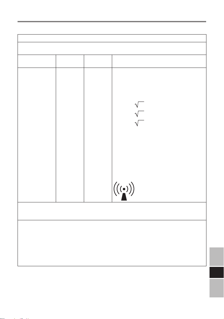
表3
d = 1.2 P
d = 1.2 P
d = 2.3 P
ガイダンスおよび製造業者による宣言 - 電磁イミュニティ
CF-VCBC11U は、次に指定した電磁環境内での使用を意図している。CF-VCBC11U の顧客
または使用者は、このような環境内でそれを用いていることを確認することが望ましい。
イミュニティ試験
JIS T 0601
試験レベル
適合レベル 電磁環境 - ガイダンス
携帯形および移動形 RF 通信機器は、ケーブル
を含む CF-VCBC11U のいかなる部分に 対し
ても、送信機の周波数に該当する方程式から計
算した推奨分離距離より近づけて使用しないこ
とが望ましい。
推奨分離距離
伝導 RF
JIS C 61000-4-6
放射 RF
JIS C 61000-4-3
注記 1. 80 MHz および 800 MHz においては、高い周波数範囲を適用する。
注記 2. これらの指針は、すべての状況に対して適用するものではない。建築物・物・人から
の吸収および反射は電磁波の伝搬に影響する。
3 Vrms
150 kHz ~
80 MHz
3 V/m
80 MHz ~
2.5 GHz
3 V
3 V/m
800 MHz ~ 2.5 GHz
ここで、Pは、送信機製造業者によるワット(W)
で表した送信機の最大定格出力電力であり、
は、メートル(m)で表した推奨分離距離であ
る。
電磁界の現地調査 *2によって決定する固定 RF
送信機からの電界強度は、各周波数範囲 *3にお
ける適合性レベルよりも低いことが望ましい。
次の記号を表示している機器の近傍では干渉が
生じるかもしれない。
*2 例えば無線(携帯/コードレス)電話および陸上移動形無線の基地局、アマチュア無線、AM・FMラジ
80 MHz ~ 800 MHz
オ放送およびTV放送のような固定送信機からの電界強度を、正確に理論的に予測をすることはで
きない。固定RF送信機による電磁環境を見積もるためには、電磁界の現地調査を考慮することが
望ましい。CF-VCBC11Uを使用する場所において測定した電界強度が上記の適用するRF適合
性レベルを超える場合は、CF-VCBC11Uが正常動作をするかを検証するために監視することが
望ましい。異常動作を確認した場合には、CF-VCBC11Uの、再配置または再設置のような追加対
策が必要となるかもしれない。
*3 周波数範囲150 kHz~80 MHzを通して、電界強度は、3 V/m未満であることが望ましい。
d
J
37
Page 38

d = 1.2 P
d = 1.2 P
d = 2.3 P
はじめに
表4
携帯形および移動形 RF 通信機器と CF-VCBC11U との間の推奨分離距離
CF-VCBC11U は、放射 RF 妨害を管理してい る電 磁環 境内 での使用を 意図 して いる。CFVCBC11U の顧客または使用者は、送信機器の最大出力に基づく次に推奨している携帯形およ
び移動形 RF 通信機器(送信機)と CF-VCBC11U との間の最小距離を維持することで、電磁
障害を抑制するのに役立つ。
送信機の周波数に基づく分離距離
送信機の
最大定格出力電力
W
0.01 0.12 0.12 0.23
0.1 0.38 0.38 0.73
1 1.2 1.2 2.3
10 3.8 3.8 7.3
100 12 12 23
上記のリストにない最大定格出力電力の送信機に関しては、メートル(m)で表した推奨分離距
離dは、送信機の周波数に対応する方程式を用いて決定できる。ここで、Pは、送信機製造業
者によるワット(W)で表した送信機の最大定格出力電力である。
注記 1. 80 MHz および 800 MHz においては、分離距離は、高い周波数範囲を適用する。
注記 2. これらの指針は、すべての状況に対して適用するものではない。建築物・物・人から
の吸収および反射は、電磁波の伝搬に影響する。
150 kHz ~ 80 MHz
m
80 MHz ~ 800 MHz
800 MHz ~ 2.5 GHz
J
38
Page 39
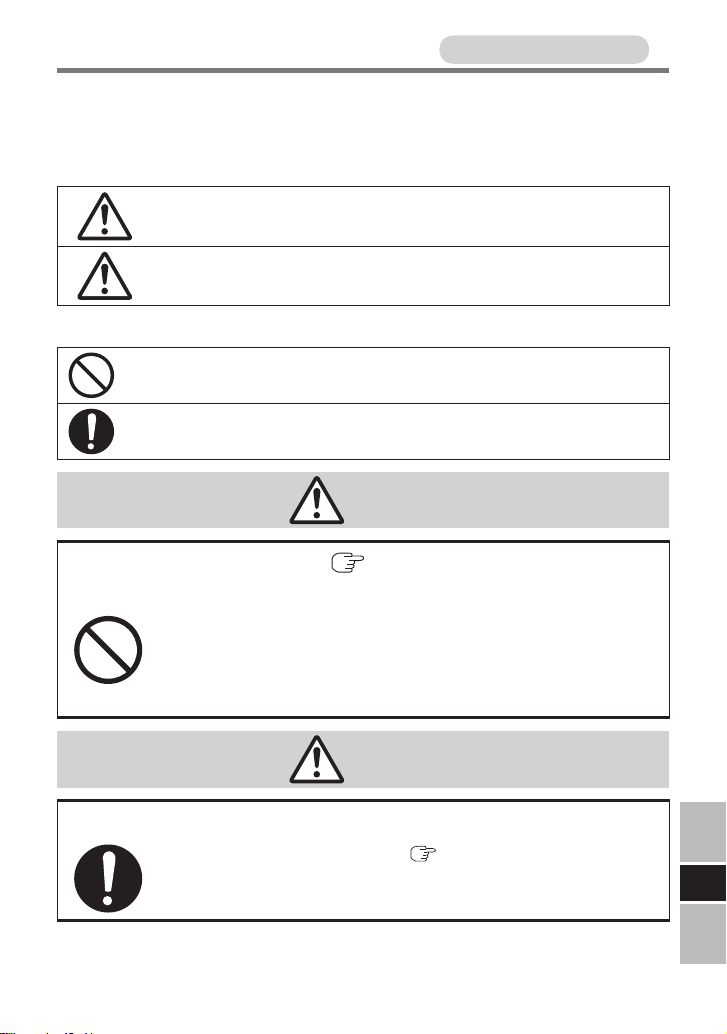
安全上のご注意
人への危害、財産の損害を防止するため、必ずお守りいただくことを説
明しています。
● 誤った使い方をしたときに生じる危害や損害の程度を区分して、説明
しています。
必ずお守りください
危険
注意
● お守りいただく内容を次の図記号で説明しています。
してはいけない内容です。
実行しなければならない内容です。
「死亡や 重 傷を負うおそ れが大き い内容」で
す。
「傷害を負うことや、財産の損害が発生するお
それがある内容」です。
危険
対応バッテリーパック(
は使用しない
バッテリー パックの液 漏 れ・発 熱・破裂 の 原 因 に なり
ます。
禁止
40ページ)以外の充電に
注意
必ず指定のACアダプターを使用する
指定(対応バッテリーパック(
種に付属および指定の別売り商品)以外のACアダプター
を使用すると、火災の原因になることがあります。
40ページ)に対応する機
J
39
Page 40

安全上のご注意
必ずお守りください
お願い
●
バッテリーパックの取り付け / 取り外しは、机など平らなところで行っ
てください。
● バッテリーチャージャーを持ち運ぶときは、バッテリーパックを取り
外してください。取り付けたまま持ち運ぶと、バッテリーパックが抜
けて落下する場合があります。
● バッテリーチャージャーのコネクターには触れないでください。
コネクターにごみや傷を付けると、正常に動作しなくなります。
● ACアダプターの取り扱いについては、パソコンに付属の取扱説明
書もご覧ください。
● コネクター部にほこりやごみなどがたまった場合
は、ACアダプターとバッテリーパックを取り外し
た後、バッテリーチャージャーを裏返して、ほこり
やごみを落としてください。ほこりなどがたまる
と、充電できなくなるなど、故障の原因になる場
合があります。定期的にほこりを取ってください。
バッテリーチャージャーに強い衝撃を与えたり、落下させたりしな
いでください。
● 対応バッテリーパック
バッテリーパック
CF-VZSU66U
1個の場合:
充電時間
約 2.5 時間
(エコノミーモード(
2個の場合:
約 3 時間
(エコノミーモード(
3個の場合:
約 4.5 時間
(エコノミーモード(
4個の場合:
約 5 時間
(エコノミーモード(
*1
エコノミーモード(ECO)の設定(有効/無効)はパソコン側で設定します。パソコンに取り
付けられているバッテリーパックにエコノミーモード(ECO)の設定が引き継がれます。
J
エコノミーモード(ECO)有効のバッテリーパックとエコノミーモード(ECO)無効の
バッテリーパックが混在していると、充電時間が長くなる場合があります。
( )内の値は、すべてのバッテリーパックがエコノミーモード(ECO)有効に設定され
ている場合の最長の充電時間です。
*1
ECO
)有効時:約4時間)
ECO
)有効時:約
ECO
)有効時:約
ECO
)有効時:約
4
7.5
7.5
時間)
時間)
時間)
40
Page 41
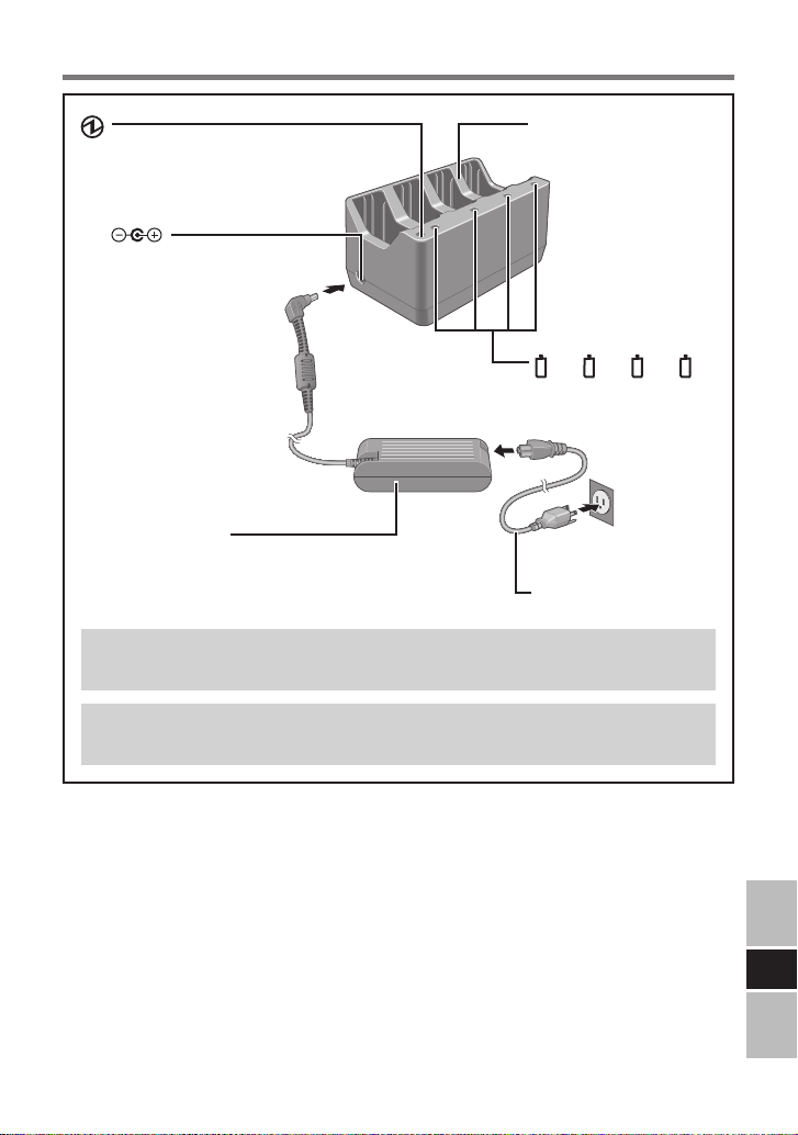
各部の名称/接続のしかた
電源状態表示ランプ
DC IN 16V
電源端子
ACアダプター
(CF-AA6503A / CF-AA6502A)
(このイラストは、CF-AA6503Aです。)
CF-AA6502Aは日本国内専用のACアダプターです。
海外ではご使用になれません。
バッテリー
チャージャー
1 2 3 4
バッテリー
状態表示ランプ
電源コード
ACアダプターおよび電源コードは、パソコン本体に付属のもの
(または指定の別売り商品)を使用してください。
J
41
Page 42

A
状態表示ランプ
● 電源状態表示ランプは、バッテリーチャージャーに電源が供給されて
いるとき(ACアダプター接続時)に緑色に点灯します。
● バッテリー状態表示ランプ
オレンジ色点灯: 充電中です。
緑色点灯: バッテリーパックの充電完了。
赤色点滅: バッテリーパックまたは充電回路が正しく動作し
ていません。
すぐにバッテリーパックとACアダプターをバッテリー
チャージャーから取り外し、取り付け直してください。
それでも赤色に点滅する場合は、ご相談窓口にご
相談ください。バッテリーパックまたは充電回路の
故障が考えられます。
オレンジ色点滅: バッテリーパック内部の温度が充 電可能な範囲
外のため、一時的に充 電できない 状態です。温
度が充電可能な範囲内になると自動的に充電が
始まります。そのままお待ちください。
無点灯: バッテリーパックが正しく取り付けられていませ
ん。または充電が始まっていません(充電待ち)。
正しく取り付けられているか確認するには、バッテ
リーパックを取り外し、取り付け直してください。
取り付けた後、バッテリー状態表示ランプが数回
点滅すればそのバッテリーパックは正しく取り付け
られています。
● 充電中にバッテリー状態表示ランプを
点灯させるか明滅させるかを設定する
ことができます。
1. AC アダプターを接続する。
2. バッテリーパックを取り外す。
3. バッテリーチャージャーを裏返す。
4. クリップを引き伸ばしたものなどを
穴(A)に挿し込み、数秒間押す。
押すごとに点灯と明滅の設定が切り替わります。
J
お願い
● パソコン本体に付属のペンなどは使わないでください。
42
Page 43

充電のしかた
1 ACアダプターを接続する。
2 バッテリーパックを取り付ける。
● バッテリーパックは同時に4個まで取り
付けることができます。
どのスロットに取り付けてもかまいま
せん。
● バッテリーパックは矢印の方向に取り
付けてください。
● バッテリーパックが正しく取り付けられ
ると、バッテリー状態表示ランプが数回点滅します。点滅しなか
った場合は、取り付け直してください。
● 自動的に充電が始まります。
● バッテリーパックを2個以上取り付けた場合は、バッテリー状態
表示ランプの番号順に2個ずつ充電されます(同時に2個のバッ
テリーパックを充電)。
(例1)バッテリーパックを4個取り付けた場合:
バッテリー状態表示ランプ 1と 2に取り付けられているバッ
テリーパックが充電されます。どちらかのバッテリーパックが満
充電になると、バッテリー状態表示ランプ 3に取り付けられて
いるバッテリーパックの充電が始まります。
(例2)バッテリー状態表示ランプ 1と 4にバッテリーパック
を取り付けた場合:
両方のバッテリーパックが充電されます。
途中でバッテリー状態表示ランプ 2にバッテリーパックを取り
付けると、バッテリー状態表示ランプ 4の充電が止まり、バッ
テリー状態表示ランプ 1と 2のバッテリーパックが充電され
ます。
● 充電時にバッテリーパックおよびバッテリーチャージャーが温か
くなることがありますが、異常ではありません。
バッテリー状態
表示ランプ
43
J
Page 44
仕様
入力電圧 16 V
定格入力電流 5.0 A
使用環境条件 温度: 5 ºC ~ 35 ºC
湿度: 30 % ~ 80 % RH(結露なきこと)
外形寸法
(幅×高さ×奥行き)
質量 約 510 g
約190 mm × 92.5 mm × 116.5 mm
保証とアフターサービス
パソコン本体の取扱説明書をご覧ください。
J
44
Page 45

MEMO
45
Page 46

Panasonic Corporation
Panasonic Solutions Company
3 Panasonic Way, Panazip 2F-5,
Secaucus, NJ 07094
Panasonic Canada Inc.
5770 Ambler Drive Mississauga,
Ontario L4W 2T3
Importer’s name & address pursuant to the EU GPSD (General
Product Safety Directive) 2001/95/EC Art.5
Panasonic Computer Products Europe, Panasonic
Marketing Europe GmbH
Hagenauer Straße 43
65203 Wiesbaden
Germany
Web Site : http://panasonic.net/
パナソニック株式会社 ITプロダクツビジネスユニット
〒570-0021 大阪府守口市八雲東町一丁目10 番12 号
© Panasonic Corporation 2010
Page 47

〈無料修理規定〉
1.
取扱説明書、本体貼付ラベル等の注意書に従った使用状態で保証期間
内に故障した場合には、無料修理をさせていただきます。
( イ )
無料修理をご依頼になる場合には、商品に取扱説明書から切り離
した本書を添えていただきお買い上げの販売店にお申しつけくだ
さい。
( ロ )
お買い上げの販売店に無料修理をご依頼にならない場合には、お
近くの修理ご相談窓口にご連絡ください。
2.
ご転居の場合の修理ご依頼先等は、お買い上げの販売店またはお近く
の修理ご相談窓口にご相談ください。
3.
ご贈答品等で本保証書に記入の販売店で無料修理をお受けになれない
場合には、お近くの修理ご相談窓口へご連絡ください。
4.保証期間内でも次の場合には原則として有料にさせていただきます。
( イ )
使用上の誤り及び不当な修理や改造による故障及び損傷
( ロ )
お買い上げ後の輸送、落下などによる故障及び損傷
( ハ )
火災、地震、水害、落雷、その他天災地変及び公害、塩害、ガス
害(硫化ガスなど)、異常電圧、指定外の使用電源(電圧、周波数)
などによる故障及び損傷
( ニ )
車両、船舶等に搭載された場合に生ずる故障及び損傷
( ホ )
本書のご添付がない場合
( へ )
本書にお買い上げ年月日、お客様名、販売店名の記入のない場
合、あるいは字句を書き替えられた場合
( ト )
持込修理の対象商品を直接修理窓口へ送付した場合の送料等はお
客様の負担となります。また、出張修理を行った場合には、出張
料はお客様の負担となります。
5.本書は日本国内においてのみ有効です。
6.本書は再発行いたしませんので大切に保管してください。
7.
お近くのご相談窓口はコンピューター本体の取扱説明書の「修理ご相
談窓口」をご参照ください。
修理メモ
※
お客様にご記入いただいた個人情報(保証書控)は、保証期間内の無
料修理対応及びその後の安全点検活動のために利用させていただく場
合がございますのでご了承ください。
※
この保証書は、本書に明示した期間、条件のもとにおいて無料修理を
お約束するものです。従ってこの保証書によって、保証書を発行して
いる者(保証責任者)、及びそれ以外の事業者に対するお客様の法律
上の権利を制限するものではありませんので、保証期間経過後の修理
についてご不明の場合は、お買い上げの販売店またはお近くの修理ご
相談窓口にお問い合わせください。
※
保証期間経過 後の 修理 や補 修用 性能 部品の保有期間についてはコン
ピューター本体の取扱説明書の「保証とアフターサービス」をご覧く
ださい。
※ThiswarrantyisvalidonlyinJapan.
Page 48
持込修理
バッテリーチャージャー保証書
本書はお買い上げの日から下記期間中故障が発生した場合には本
書裏面記載内容で無料修理を行うことをお約束するものです。ご
記入いただきました個人情報の利用目的は本票裏面に記載してお
ります。お客様の個人情報に関するお問い合わせは、お買い上げ
の販売店にご相談ください。詳細は裏面をご参照ください。
品 番
保証期間
※
お買い上げ日
※
ご住 所
お
客
お名前
様
電 話
※
CF-VCBC11U
お買い上げ日から
本体1年間
( ) ー
年 月 日
様
住所・販売店名
販
売
店
( ) ー
電話
パナソニック株式会社 ITプロダクツビジネスユニット
〒 570-0021 大阪府守口市八雲東町一丁目 10 番 12 号 TEL(06)6908-1001
(切 り 取 り 線)
ご販売店様へ ※印欄は必ず記入してお渡しください。
 Loading...