


CTi Automation - Phone: 800.894.0412 - Fax: 208.368.0415 - Web: www.ctiautomation.net - Email: info@ctiautomation.net
Operator Interface Stations
USER’S MANUAL
Setup & Operation
CONTENTS
For Toshiba PLCs
& Other Automation Equipment
Toshiba International Corporation

UMAN/OIS
CTi Automation - Phone: 800.894.0412 - Fax: 208.368.0415 - Web: www.ctiautomation.net - Email: info@ctiautomation.net
Thank you for purchasing the OIS (Operator Interface Station) Series product from
Toshiba International Corp. OIS Series products are versatile operator interfaces which
are configured with Microsoft Windows® based software.
Manual’s Purpose and Scope
This manual provides information on how to safely install, operate, and
maintain your TIC OIS (Operator Interface Station). This manual includes a
section of general safety instructions that describes the warning labels and
symbols that are used throughout the manual. Read the manual completely
before installing, operating, or performing maintenance on this equipment.
This manual and the accompanying drawings should be considered a
permanent part of the equipment and should be readily available for reference
and review. Dimensions shown in the manual are in metric and/or the English
equivalent.
Toshiba International Corporation reserves the right, without prior notice, to
update information, make product changes, or to discontinue any product or
service identified in this publication.
TOSHIBA is a registered trademark of the Toshiba Corporation. All other
product or trade references appearing in this manual are registered
trademarks of their respective owners.
Toshiba International Corporation (TIC) shall not be liable for technical
or editorial omissions or mistakes in this manual, nor shall it be liable
for incidental or consequential damages resulting from the use of
information contained in this manual.
This manual is copyrighted. No part of this manual may be photocopied or
reproduced in any form without the prior written consent of Toshiba
International Corporation.
© Copyright 2004 Toshiba International Corporation.
© Copyright 2004 Renu Electronics Pvt. Ltd.
All rights reserved.
Printed in the U.S.A.
Page ii

UMAN/OIS
CTi Automation - Phone: 800.894.0412 - Fax: 208.368.0415 - Web: www.ctiautomation.net - Email: info@ctiautomation.net
Important Notice
The instructions contained in this manual are not intended to cover all details
or variations in equipment types, nor may it provide for every possible
contingency concerning the installation, operation, or maintenance of this
equipment. Should additional information be required contact your Toshiba
representative.
The contents of this manual shall not become a part of or modify any prior or
existing agreement, commitment, or relationship. The sales contract contains
the entire obligation of Toshiba International Corporation. The warranty
contained in the contract between the parties is the sole warranty of Toshiba
International Corporation and any statements contained herein do not create
new warranties or modify the existing warranty.
Any electrical or mechanical modifications to this equipment without prior
written consent of Toshiba International Corporation will void all warranties
and may void the 3rd party (CE, UL, CSA, etc) safety certifications.
Unauthorized modifications may also result in a safety hazard or equipment
damage.
Contacting Toshiba’s Customer
Support Center
Toshiba’s Customer Support Center may be contacted to obtain help in
resolving any system problems that you may experience or to provide
application information.
The center is open from 8 a.m. to 5 p.m. (CST), Monday through Friday. The
Support Center’s toll free number is US 800-231-1412 Fax 713-466-8773
— Canada 800-527-1204 — Mexico 01-800-527-1204.
You may also contact Toshiba by writing to:
Toshiba International Corporation
13131 West Little York Road
Houston, Texas 77041-9990
Attn: PLC Marketing
or
plc@tic.toshiba.com
Page iii

UMAN/OIS
CTi Automation - Phone: 800.894.0412 - Fax: 208.368.0415 - Web: www.ctiautomation.net - Email: info@ctiautomation.net
Manual Revisions
Please have the following information available when contacting Toshiba International
Corp. about this manual.
Name: OIS User’s Manual
Document: UMAN\OIS
Revision:
Rev No. Date Description
0 2003/06 Initial Issue (for OIS60)
1 2006/06 EV3 Upgrade Documentation
Add OIS40/50/120
3 2008/02 Upgrade for OISetup32 V3.12 Features
Page iv

UMAN/OIS
CTi Automation - Phone: 800.894.0412 - Fax: 208.368.0415 - Web: www.ctiautomation.net - Email: info@ctiautomation.net
Table of Contents
0. General Safety Instructions and Information ............................................ 1
0.1 Warning Labels Within Manual....................................................................................2
0.2 Equipment Warning Labels. .........................................................................................4
0.3 Preparation........................................................................................................................5
0.4 Installation Precautions.................................................................................................6
0.5 Connection, Protection & Setup..................................................................................8
0.6 System Integration Precautions................................................................................10
0.7 3rd Party Safety Certifications....................................................................................11
1. Introduction ........................................................................................................ 12
1.1 Purpose of this Manual...........................................................................................13
1.1.1 OIS Basics.........................................................................................................13
1.1.2 Hardware Requirements.................................................................................14
1.2 OIS Overview ..................................................................................................................15
1.2.1 What is an OIS?......................................................................................................15
1.2.2 How the OIS Works................................................................................................16
1.2.3 Specifi cations of OIS Series......................................................................20
1.2.4 Comparison Between Keypad Based OIS Operator Panels .............20
1.2.5 Comparison Between Touchscreen Based OIS Panels.....................21
2. Hardware ............................................................................................................. 28
2.1 Unpacking The Unit..............................................................................................29
2.2 Managing Electrostatic Discharge..............................................................29
2.3 CE Compliance.......................................................................................................29
2.4 Environmental Rating .......................................................................................29
2.5 Environmental Consideration........................................................................29
2.6 Safety Precaution...............................................................................................30
2.7 Installation Instructions...................................................................................30
2.7.1 Panel Cutouts for OIS Models .......................................................................31
2.7.2 Not Included at This Time. .........................................................................................33
2.8 Wiring Diagrams.........................................................................................................34
2.9 Communication Ports...............................................................................................34
3. Before You Begin .............................................................................................. 35
3.1 Connecting the OIS to a Computer.......................................................................36
3.2 Starting OISetup32 Software..................................................................................37
3.2.1 Installing OISetup32 Softw
3.2.2 Steps for starting OISetup32 Software........................................................39
3.2.3 Uninstallin
3.3 Setting Network Configuration ...........................................................................40
4. Using OISetup32 Software............................................................................. 45
4. 1 OIS Menu Structure.......................................................................................................46
4.1.1 File Menu ..................................................................................................................49
4.1.2 Define Menu.............................................................................................................49
4.1.3 Communicate Menu...............................................................................................50
4.1.4 Utilities Menu...........................................................................................................50
4.1.5 Help Menu.................................................................................................................51
g OISetup32 Software..................................................................39
are............................................................................37
Page v

UMAN/OIS
CTi Automation - Phone: 800.894.0412 - Fax: 208.368.0415 - Web: www.ctiautomation.net - Email: info@ctiautomation.net
4. 2 Creating a New Application.......................................................................................51
4.3 Creating Screens...........................................................................................................58
4.3.1 Protecting OIS Application..................................................................................59
4.3.2 Protecting OIS Screen...........................................................................................59
4.4 Data Entry Object..........................................................................................................60
4.5 Display OIS Or PLC Data Object................................................................................60
4.6 Global And Power On Task.........................................................................................60
4 . 7 Global Keys....................................................................................................................62
4.8 Screen Keys...................................................................................................................63
5. Representing Data by Objects and Objects ............................................. 64
5.1 Alphanumeric Objects...................................................................................................65
5.1.1 Text Object..........................................................................................................65
5.1.2 Data Entry Object..............................................................................................65
5.1.3 Display OIS Or PLC Data Object Procedure ..........................................67
5.1.4 Time..........................................................................................................................70
5.1.5 Date..........................................................................................................................70
5. 2 Graphic Objects............................................................................................................75
5.2.1 Line...........................................................................................................................76
5.2.2 Rectangle.................................................................................................................76
5.2.3 Ellipse ......................................................................................................................77
5.2.4 Rounded Rectangle .......................................................................................77
5.2.5 Bargraph..................................................................................................................78
5.2.6 Bitmap......................................................................................................................78
5.3 Wizards............................................................................................................................81
5.3.1 Bit Button ................................................................................................................82
5.3.2 Word Button.......................................................................................................86
5.3.3 Bit Lamp..................................................................................................................89
5.3.4 Word Lamp .........................................................................................................93
5.3.5 Multiple Bargraph..................................................................................................95
5.3.6 Analog Meter ...................................................................................................101
5.3.7 Real Time Trend ............................................................................................107
5.3.8 Numeric Keypad ............................................................................................112
5.3.9 ASCII Keypad..........................................................................................................115
6. Task Management........................................................................................... 117
6. 1 Application Task List .................................................................................................118
6. 2 Screen Task List.........................................................................................................119
6.3 Key Task List................................................................................................................121
6.3.1 For Keypad Products .........................................................................................122
6.3.2 For Touch Screen Products .....................................................................123
6.4 Description of Tasks..................................................................................................124
7. Using Languages............................................................................................. 141
7.1 Language Conversion Utility....................................................................................142
7.1.1 File Menu ................................................................................................................142
7.1.2 Edit Menu................................................................................................................145
7.1.3 View Menu ..........................................................................................................145
7.2 Multi-Language Text Wizard.....................................................................................145
7.2.1 Configure Languages.........................................................................................146
7.2.2 Displaying Multiple Languages in Unit..........................................................148
Page vi

UMAN/OIS
CTi Automation - Phone: 800.894.0412 - Fax: 208.368.0415 - Web: www.ctiautomation.net - Email: info@ctiautomation.net
8. DownLoading & UpLoading from the OIS................................................ 149
8.2 Download.......................................................................................................................152
9. Alarms................................................................................................................. 156
9.1 Defining Alarms...........................................................................................................157
9.2 Alarm Definition...........................................................................................................158
9.3 Alarm Object............................................................................................................159
9.4 Alarm Type....................................................................................................................160
10. Trending........................................................................................................... 161
10.1 Real Time Trending..................................................................................................162
10.2 Data Logger................................................................................................................167
10.3 Historical Trend.........................................................................................................171
11. {Section Not Included at this Time}........................................................ 177
12. Printing............................................................................................................. 178
12.1 Printing from OIS Unit............................................................................................179
12.2 Printing from OISetup32 Software.......................................................................180
12.3 Printer Port Setup.....................................................................................................181
13. Miscellaneous................................................................................................ 184
13.2 Font Editor..................................................................................................................186
13.3 Associate a Screen ..................................................................................................190
13.4 Real Time Clock........................................................................................................191
13.5 On-Line Ladder Monitor..........................................................................................193
13.6 On-Line Screen Monitor...........................................................................................198
13.7 Convert Application..................................................................................................205
13.8 Ethernet Settings.......................................................................................................206
14. Diagnostics & Maintenance...................................................................... 215
14 . 1 Diagnostics................................................................................................................216
14.1.1 Erase Keys..........................................................................................................216
14.1.2 Touchscreen Calibration.................................................................................218
14.2 Maintenance................................................................................................................218
Appendix.................................................................................................................. 219
A. Communication Cable Diagrams..............................................................................220
C. Order Numbers..............................................................................................................232
D. Description of Tool Icons............................................................................................233
E. List of Supported Devices.........................................................................................236
16. Frequently Asked Questions..................................................................... 237
Index ......................................................................................................................... 239
Page vii

UMAN/OIS
CTi Automation - Phone: 800.894.0412 - Fax: 208.368.0415 - Web: www.ctiautomation.net - Email: info@ctiautomation.net
Page viii

UMAN/OIS
CTi Automation - Phone: 800.894.0412 - Fax: 208.368.0415 - Web: www.ctiautomation.net - Email: info@ctiautomation.net
0. General Safety Instructions and Information
Warning Labels Within Manual
Equipment Warning Labels
Preparation
Installation Precautions
Connection, Protection & Setup
System Integration Precautions
3rd Party Safety Certifications
Page 1
0.1 Warning Labels Within Manual
R
CTi Automation - Phone: 800.894.0412 - Fax: 208.368.0415 - Web: www.ctiautomation.net - Email: info@ctiautomation.net
DO NOT attempt to install, operate, maintain, or dispose of this equipment
until you have read and understood all of the product warnings and user
directions that are contained in this instruction manual.
Listed below are the signal words that are used throughout this manual
followed by their descriptions and associated symbols. When the words
DANGER, WARNING, and CAUTION are used in the manual, they will be
followed by important safety information that must be carefully adhered to.
DANGER — The danger symbol is an exclamation mark enclosed in a triangle
that precedes the word DANGER. The danger symbol is used to indicate an
imminently hazardous situation that will result in serious injury, possible
severe property and equipment damage, or death if the instructions are not
followed.
DANGE
UMAN/OIS
WARNING — The warning symbol is an exclamation mark enclosed in a
triangle that precedes the word WARNING. The warning symbol is used to
indicate a potentially hazardous situation that can result in serious injury, or
possibly severe property and equipment damage, or death, if the instructions
are not followed.
WARNING
CAUTION — The caution symbol is an exclamation mark enclosed in a
triangle that precedes the word CAUTION. The caution symbol is used to
indicate situations that can result in minor or moderate operator injury, or
equipment damage if the instructions are not followed.
CAUT ION
Page 2
UMAN/OIS
L
CTi Automation - Phone: 800.894.0412 - Fax: 208.368.0415 - Web: www.ctiautomation.net - Email: info@ctiautomation.net
To identify special hazards, other symbols may appear in conjunction with the
DANGER, WARNING, and CAUTION symbols. These warnings describe
areas that require special care and/or strict adherence to the procedures to
prevent serious injury and possible death.
Electrical Hazard — The electrical hazard symbol is a lightning bolt enclosed
in a triangle. The electrical hazard symbol is used to indicate high voltage
locations and conditions that may cause serious injury or death if the proper
precautions are not observed.
ELECTRICA
HAZARD
Explosion Hazard — The explosion hazard symbol is an explosion image
enclosed in a triangle. The explosion hazard symbol is used to indicate
locations and conditions where molten exploding parts may cause serious
injury or death if the proper precautions are not observed.
EXPLOSION
HAZARD
Page 3

0.2 Equipment Warning Labels.
CTi Automation - Phone: 800.894.0412 - Fax: 208.368.0415 - Web: www.ctiautomation.net - Email: info@ctiautomation.net
DO NOT attempt to install, operate, maintain, or dispose of this equipment
until you have read and understood all of the product warnings and user
directions that are contained in this instruction manual.
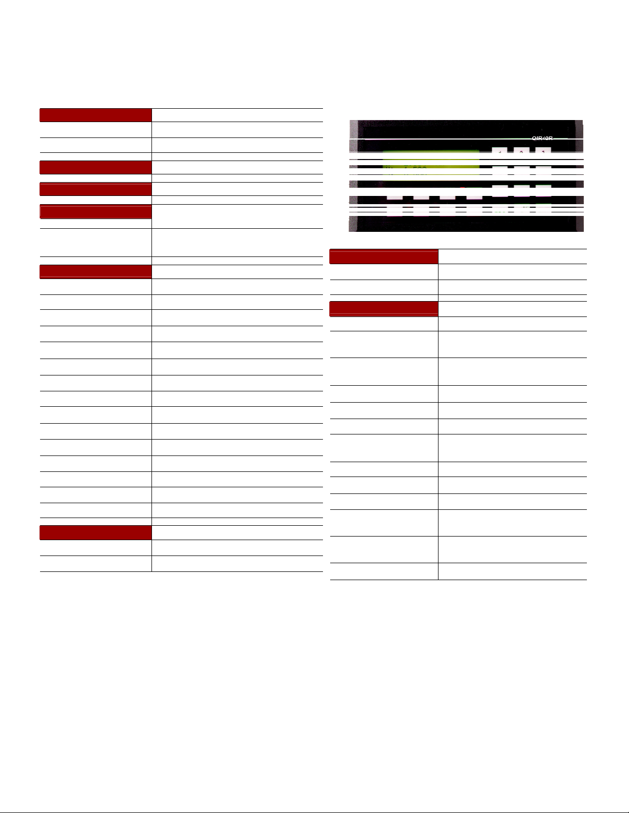
Shown below are examples of warning labels that may be found attached to
the equipment. DO NOT remove or cover any of the labels. If the labels are
damaged or if additional labels are required, contact your Toshiba
representative for additional labels.
The following are examples of the warning labels that may be found on the
equipment and are there to provide useful information or to indicate an
imminently hazardous situation that may result in serious injury, severe
property and equipment damage, or death if the instructions are not followed.
Examples of labels that may be found on the equipment.
UMAN/OIS
Page 4

0.3 Preparation
CTi Automation - Phone: 800.894.0412 - Fax: 208.368.0415 - Web: www.ctiautomation.net - Email: info@ctiautomation.net
Qualified Person
A Qualified Person is one that has the skills and knowledge relating to the
construction, installation, operation, and maintenance of the electrical
equipment and has received safety training on the hazards involved (Refer to
the latest edition of NFPA 70E for additional safety requirements).
Qualified Personnel shall:
• Have carefully read the entire operation manual.
• Be trained and authorized to safely energize, de-energize, ground, lockout
and tag circuits and equipment, and clear faults in accordance with
established safety practices.
• Be trained in the proper care and use of protective equipment such as
safety shoes, rubber gloves, hard hats, safety glasses, face shields, flash
clothing, etc., in accordance with established safety practices.
• Be trained in rendering first aid.
UMAN/OIS
For further information on workplace safety visit www.osha.gov.
Equipment Inspection
• Upon receipt of the equipment inspect the packaging and equipment for
shipping damage.
• Carefully unpack the equipment and check for parts that were damaged
from shipping, missing parts, or concealed damage. If any discrepancies
are discovered, it should be noted with the carrier prior to accepting the
shipment, if possible. File a claim with the carrier if necessary and
immediately notify your Toshiba representative.
• DO NOT install or energize equipment that has been damaged. Damaged
equipment may fail during operation resulting in further equipment damage
or personal injury.
• Check to see that the model number specified on the nameplate conforms
to the order specifications.
• Modification of this equipment is dangerous and must not be performed
except by factory trained representatives. When modifications are required
contact your Toshiba representative.
• Inspections may be required before and after moving installed equipment.
• Keep the equipment in an upright position as indicated on the shipping
carton.
• Contact your Toshiba representative for assistance if required.
Page 5

UMAN/OIS
CTi Automation - Phone: 800.894.0412 - Fax: 208.368.0415 - Web: www.ctiautomation.net - Email: info@ctiautomation.net
Handling and Storage
• Use proper lifting techniques when moving the OIS; including properly
sizing up the load, and getting assistance if required.
• Store in a well-ventilated covered location and preferably in the original
carton if the equipment will not be used upon receipt.
• Store in a cool, clean, and dry location. Avoid storage locations with
extreme temperatures, rapid temperature changes, high humidity, moisture,
dust, corrosive gases, or metal particles.
• Do not store the unit in places that are exposed to outside weather
conditions (i.e., wind, rain, snow, etc.).
• Store in an upright position as indicated on the shipping carton.
• Include any other product-specific requirements.
Disposal
Never dispose of electrical components via incineration. Contact your state
environmental agency for details on disposal of electrical components and
packaging in your area.
0.4 Installation Precautions
Location and Ambient Requirements
• Adequate personnel working space and adequate illumination must be
provided for adjustment, inspection, and maintenance of the equipment
(refer to NEC Article 110-34).
• Avoid installation in areas where vibration, heat, humidity, dust, fibers,
steel particles, explosive/corrosive mists or gases, or sources of electrical
noise are present.
• The installation location shall not be exposed to direct sunlight.
• Allow proper clearance spaces for installation. Do not obstruct the
ventilation openings. Refer to the recommended minimum installation
dimensions as shown on the enclosure outline drawings.
• The ambient operating temperature shall be between 0° and 50° C (32°
and 122° F).
Mounting Requirements
• Only Qualified Personnel should install this equipment.
• Install the unit in a secure upright position in a well-ventilated area.
• A noncombustible insulating floor or mat should be provided in the area
immediately surrounding the electrical system at the place where
maintenance operations are to be performed.
Page 6

UMAN/OIS
CTi Automation - Phone: 800.894.0412 - Fax: 208.368.0415 - Web: www.ctiautomation.net - Email: info@ctiautomation.net
• As a minimum, the installation of the equipment should conform to the
NEC Article 110 Requirements For Electrical Installations, OSHA, as well
as any other applicable national, regional, or industry codes and standards.
• Installation practices should conform to the latest revision of NFPA 70E
Electrical Safety Requirements for Employee Workplaces.
Conductor Routing and Grounding
• Use separate metal conduits for routing the input power, and control
circuits.
• A separate ground cable should be run inside the conduit with the input
power, and control circuits.
• DO NOT connect control terminal strip return marked CC to earth ground.
• Always ground the unit to prevent electrical shock and to help reduce
electrical noise.
The Metal Of Conduit Is Not An Acceptable
Ground.
Page 7

0.5 Connection, Protection & Setup
CTi Automation - Phone: 800.894.0412 - Fax: 208.368.0415 - Web: www.ctiautomation.net - Email: info@ctiautomation.net
Personnel Protection
• Installation, operation, and maintenance shall be performed by Qualified
Personnel Only.
• A thorough understanding of the OIS will be required before the installation,
operation, or maintenance of the OIS.
• Rotating machinery and live conductors can be hazardous and shall not
come into contact with humans. Personnel should be protected from all
rotating machinery and electrical hazards at all times. Depending on its
program, the OIS can initiate the start and stop of rotating machinery.
• Insulators, machine guards, and electrical safeguards may fail or be
defeated by the purposeful or inadvertent actions of workers. Insulators,
machine guards, and electrical safeguards are to be inspected (and tested
where possible) at installation and periodically after installation for potential
hazardous conditions.
• Do not allow personnel near rotating machinery. Warning signs to this
effect shall be posted at or near the machinery.
UMAN/OIS
• Do not allow personnel near electrical conductors. Human contact with
electrical conductors can be fatal. Warning signs to this effect shall be
posted at or near the hazard.
• Personal protection equipment shall be provided and used to protect
employees from any hazards inherent to system operation or maintenance.
System Setup Requirements
• When using the OIS as an integral part of a larger system, it is the
responsibility of the OIS installer or maintenance personnel to ensure that
there is a fail-safe in place (i.e., an arrangement designed to switch the
system to a safe condition if there is a fault or failure).
• System safety features should be employed and designed into the
integrated system in a manner such that system operation, even in the
event of system failure, will not cause harm or result in personnel injury or
system damage (i.e., E-Off, Auto-Restart settings, System Interlocks, etc.).
• The programming setup and system configuration of the OIS may allow it
to start a motor unexpectedly. A familiarity with Auto-restart settings is a
requirement to use this product.
• Improperly designed or improperly installed system interlocks may render
the motor unable to start or stop on command.
Page 8

UMAN/OIS
CTi Automation - Phone: 800.894.0412 - Fax: 208.368.0415 - Web: www.ctiautomation.net - Email: info@ctiautomation.net
• The failure of external or ancillary components may cause intermittent
system operation, i.e., the system may start a motor without warning or
may not stop on command.
• There may be thermal or physical properties, or ancillary devices
integrated into the overall system that may allow the OIS to start a motor
without warning. Signs at the equipment installation must be posted to this
effect.
• The operating controls and system status indicators should be clearly
readable and positioned where the operator can see them without
obstruction.
• Additional warnings and notifications shall be posted at the equipment
installation location as deemed required by Qualified Personnel.
Page 9

CTi Automation - Phone: 800.894.0412 - Fax: 208.368.0415 - Web: www.ctiautomation.net - Email: info@ctiautomation.net
0.6 System Integration Precautions
The following precautions are provided as general guidelines for using an OIS
in an industrial or process control system.
• The Toshiba OIS is a general-purpose product. It is a system component
and is used in conjunction with other items of industrial equipment such as
PLCs, Loop Controllers, Adjustable Speed Drives, etc.
• A detailed system analysis and job safety analysis should be
performed by the systems designer or systems integrator before
including the OIS in any new or existing system. Contact Toshiba for
options availability and for application-specific system integration
information if required.
• The OIS may be used to control an adjustable speed drive connected to
high voltage sources and rotating machinery that is inherently dangerous if
not operated safely. Interlock all energy sources, hazardous locations,
and guards in order to restrict the exposure of personnel to hazards. The
adjustable speed drive may start the motor without warning. Signs at the
equipment installation must be posted to this effect. A familiarity with Autorestart settings is a requirement when controlling adjustable speed drives.
Failure of external or ancillary components may cause intermittent system
operation, i.e., the system may start the motor without warning or may not
stop on command. Improperly designed or improperly installed
system interlocks and permissives may render a motor unable to
start or stop on command
UMAN/OIS
• Control through serial communications can fail or can also override local
controls, which can create an unsafe condition. System safety features
should be employed and designed into the integrated system in a manner
such that system operation, even in the event of system failure, will not
cause harm or result in personnel injury or system damage. Use of the
built-in system protective features and interlocks of the equipment being
controlled is highly recommended (i.e., emergency-off, overload protection,
etc.)
• Never use the OIS units to perform emergency stops. Separate
switches outside the OIS, the PLC, and the ASD should be used for
emergency stops.
• Changes or modifications to the OIS program should not be made without
the approval of the system designer or systems integrator. Minor changes
or modifications could cause the defeat of safety interlocks and
permissives. Any changes or modifications should be noted and included
with the system documentation.
Page 10
0.7 3rd Party Safety Certifications.
CTi Automation - Phone: 800.894.0412 - Fax: 208.368.0415 - Web: www.ctiautomation.net - Email: info@ctiautomation.net
UMAN/OIS
CE Marking
Page 11

UMAN/OIS
CTi Automation - Phone: 800.894.0412 - Fax: 208.368.0415 - Web: www.ctiautomation.net - Email: info@ctiautomation.net
1. Introduction
Purpose of Manual
OIS Basics
Hardware Configuration
OIS Overview
What is OIS
OIS Specifications
Page 12

CTi Automation - Phone: 800.894.0412 - Fax: 208.368.0415 - Web: www.ctiautomation.net - Email: info@ctiautomation.net
1.1 Purpose of this Manual
Thank you for purchasing OIS EV3 Series Products from Toshiba International
Corp.. OIS Series Products are versatile operator interfaces with Microsoft
Windows based configuration Software.
This Manual explains the operation of the OIS Series and how to implement
available features using the OIS32 Soft-ware. This manual will help you to install,
configure and operate your OIS product.
1.1.1 OIS Basics
Operator Interface Terminals (OISs) provide much more versatility than traditional
mechanical control panels. An OIS allows a plant floor operator to monitor current
conditions of a control system and, if necessary, to initiate a change in the operation of the system. OISs connect to programmable logic controllers (PLCs) typically
through the serial communications port. The OIS can be programmed to monitor
and/or change current values stored in the data memory of the PLC.
UMAN/OIS
OISs can have either text or graphics based displays. A text based OIS can
display printable text characters but can not print graphics.
Some OISs use touch screen displays while others use a PCB based keypad. PCB
based keypads are best used in applications in which the keypad is likely to
become dirty. A touch screen OIS provides much more flexibility than typical PCB
based keypad displays. Keys can be created in a touch screen OIS that can be
made visible only when needed. The OIS Series OISs are available in both text
display based OIS and graphics display based OISs.
What is a Project?
A project is an user created application in OIS32 Software. A project contains
information such as OIS model, Network Configuration, Screen information, Task
information et c.
What is a Screen?
A screen is a visual representation of objects placed on the OIS screen. Any
partially sized window is usually referred to as a popup screen or window. The user
can create his customized screen according to his requirements. Popup wind ows
can also appear on the OIS display by pressing buttons on the touch screen . The
maximum number of screens in an application is only limited by the application
memory size. A more in depth discussion on screens is covered in chapter 4.
Page 13

UMAN/OIS
CTi Automation - Phone: 800.894.0412 - Fax: 208.368.0415 - Web: www.ctiautomation.net - Email: info@ctiautomation.net
What is an Object?
An object placed on OIS screen can perform actions such as displaying text
messages, writing a value to a PLC register, or displaying an alarm. An object can
be classified as a text or graphical object.
A text object is used to display the text on the OIS and can also used to perform
some action. For example, a data entry object tells the OIS to continuously monitor
a PLC register and allows the user to change the value in the register. Some
objects can display graphics whose shape depends on the value of a register.
These objects may also change the value of a PLC tag. An example is a Bit Button
Object that creates a graphic object on the OIS. When pressed, it activates a bit in
the PLC.
1.1.2 Hardware Requirements
The following basic PC hardware configuration is needed to configure and operate your
OIS32 Software.
DEVICE MINIMUM REQUIREMENT
IBM Compatible PC with
Pentium Processor
Operating System Windows® 2000 and above
System RAM
Hard Disk 150 MB Free Memory Space
VGA Monitor Color
Setting Resolution
Serial Port
Mouse
Keyboard Required
266MHz Pentium® II or higher Pentium
compatible CPU
At least 64 megabytes (MB) of RAM, more
memory generally improves responsiveness
800 x 600 with 24 bit True Color
Serial Port for Downloading
Microsoft® Mouse or compatible pointing device
These are the minimum system requirements for a computer running the OISetup32 software.
Page 14

1.2 OIS Overview
CTi Automation - Phone: 800.894.0412 - Fax: 208.368.0415 - Web: www.ctiautomation.net - Email: info@ctiautomation.net
1.2.1 What is an OIS?
OIS provide Human-Machine Interface to the Pr ogrammable L ogic Cont roller. These OISs
communicate with PLCs using their serial communications ports.
Configuration of OIS:
Each OIS unit has to be configured using the OISetup32 Software before connecting it to the PLC.
Normal Operation:
UMAN/OIS
Connect OIS unit to PLC using the correct PLC-OIS cable. The OIS can communicate with any
device without making any additional hardware settings on the unit.
Page 15
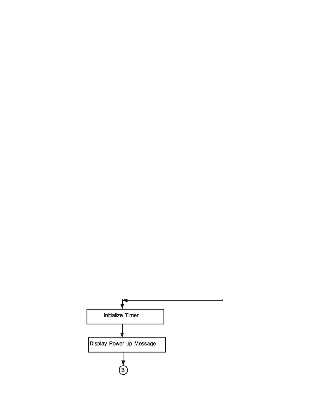
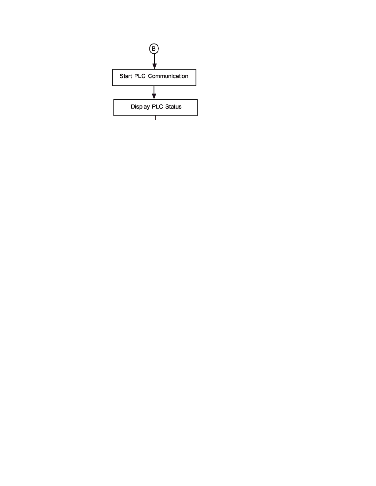
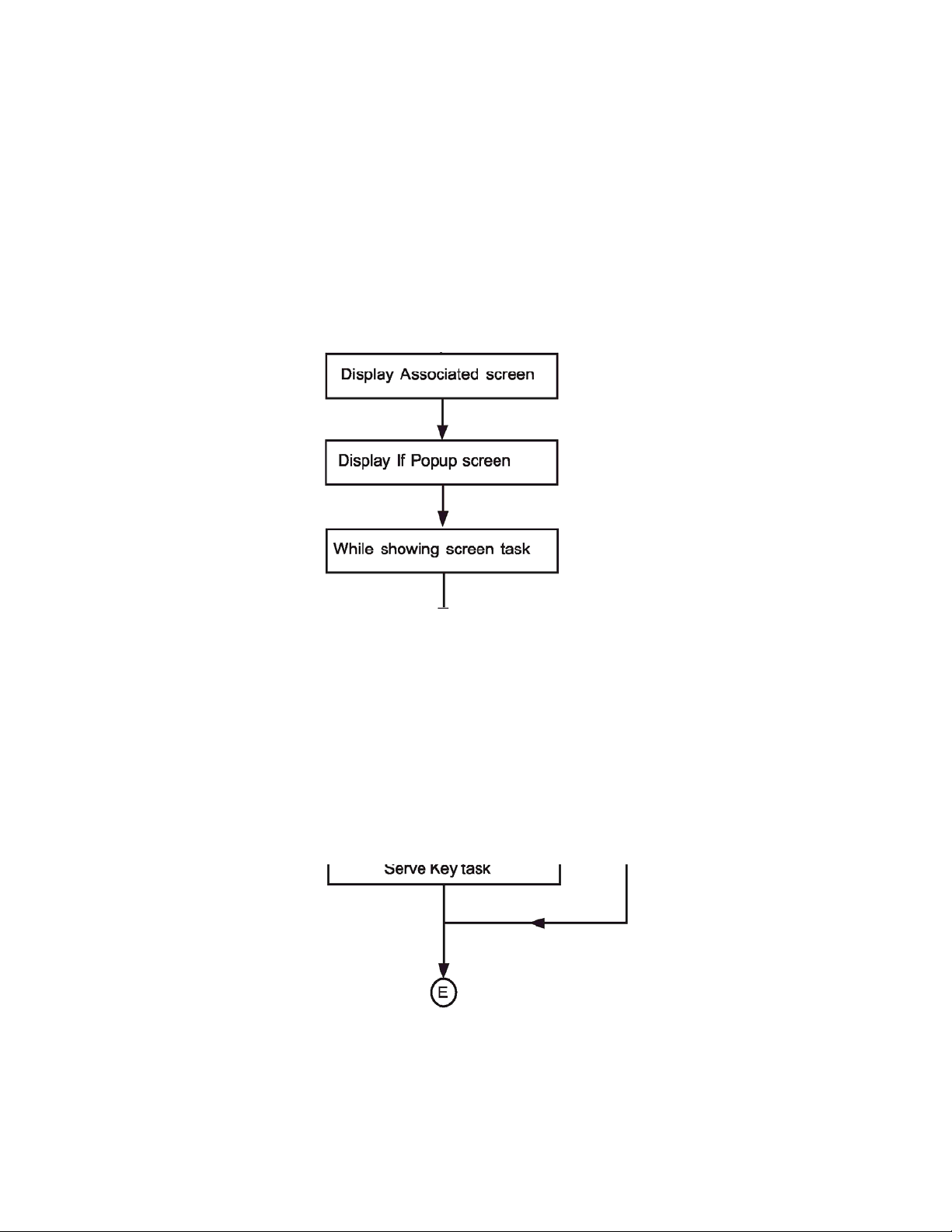
1.2.2 How the OIS Works
CTi Automation - Phone: 800.894.0412 - Fax: 208.368.0415 - Web: www.ctiautomation.net - Email: info@ctiautomation.net
The OIS follows a specific sequence for performin g the ta sks defined by the user in the
application. The sequence is as shown below:
UMAN/OIS
Page 16
UMAN/OIS
CTi Automation - Phone: 800.894.0412 - Fax: 208.368.0415 - Web: www.ctiautomation.net - Email: info@ctiautomation.net
Page 17
UMAN/OIS
CTi Automation - Phone: 800.894.0412 - Fax: 208.368.0415 - Web: www.ctiautomation.net - Email: info@ctiautomation.net
Page 18

UMAN/OIS
CTi Automation - Phone: 800.894.0412 - Fax: 208.368.0415 - Web: www.ctiautomation.net - Email: info@ctiautomation.net
Page 19

UMAN/OIS
CTi Automation - Phone: 800.894.0412 - Fax: 208.368.0415 - Web: www.ctiautomation.net - Email: info@ctiautomation.net
1.2.3 Specifications of OIS Series
OIS series models are Human Machine Interfaces with optional Input/Output capability. OISs with
Input/Output capability are termed as HIO. OIS series OISs can be powered either from the PLC or from an
external power supply. PLC powered units are referred to as IOP, whereas externally powered units are
referred to as OIS. HIO units can not be powered from a PLC. HIO models can be externally from a DC or
AC source.
OIS models need +24VDC power from an external supply. HIO can either be external +24VDC powered or
85-265, 50/ 60Hz VAC powered.
Models included in the OIS Series are as follows:
OIS40/40R OIS50 OIS55 OIS60 OIS120
The functionality of OIS and HIO products is exactly the same. The only difference between a OIS
product and an HIO product is the addition of real I/O to the HIO unit. A OIS application can be
downloaded to a corresponding HIO model. All of the OIS EV3 series models have ladder functionality
built in.
All OIS EV3 series models have two serial communication ports. They can communicate with two
different PLCs simultaneously.
1.2.4 Comparison Between Keypad Based OIS Operator Panels
Model OIS40 OIS40R
Display 128 X 64 Pixels 128 X 64 Pixels
Keys Function 8 User Definable 8 User Definable
LEDs 8 8
Memory Total 512 KB 512 KB
Data Logging N. A. N. A.
Trending N. A. N. A.
Alarms Real Time
Recipes Yes Yes
Password Yes Yes Yes
Dimensions 101 HX183WX37D 101 HX183WX37D 101 HX183WX37D
Numeric 12 12
Application 120 KB 120 KB
Ladder 62 KB 62 KB
Historical
Yes Yes Yes
163W X 77H mm 163W X 77H mm 163W X 77H mm
Real Time
Historical
Page 20

1.2.5 Comparison Between Touchscreen Based OIS Panels
*
CTi Automation - Phone: 800.894.0412 - Fax: 208.368.0415 - Web: www.ctiautomation.net - Email: info@ctiautomation.net
Model OIS50 OIS55 OIS60 OIS120
Display
Type
Resolution 192 X 62 Pixels 320 X 240 Pixels 320 X 240 Pixels 800 X 600 Pixels
Brightness
Control
Touchscree
n
Total 512 KB 3 MB 4 MB 32 MB
Applicati
on
Ladder 62 KB 512 KB 128 KB 2 MB
Memory
Data
Logging
Data
Logging
Trending N.A. Real Time
4.1” Yellow Backlit
LCD
Graphical Display
Standard Through
Pot
Analog Resistive Analog Resistive Analog Resistive Analog Resistiv
120 KB 2.56 MB 3 MB Maximum* 25 MB Maximum
N.A. N.A. 2 MB* 2 MB*
N.A. N.A. Yes Yes
3.5" TFT Graphical
Color Display,
6 Function Keys
5.7” STN CCFL
QVGA
Graphical Color
Standard Through
Pot
Real Time +
Historical
12.1: TFT CCFL
Graphical Color
Standard Thru.
Pot
Real Time +
Historical
UMAN/OIS
Alarms
Recipes Yes Yes Yes Yes
ScreenSave
r
Screen Yes Yes Yes Yes
P
W
Applicati
on
External
Dimensi
Di
ons
m
Panel
Cutout
Real Time +
Historical
N.A. Yes Yes Yes
Yes Yes Yes Yes
77HX140WX32D 91Hx136W x29D 139HX197WX58.5D 246HX312WX47
132W X 69H mm 127W x 77H 184W X 126H mm 295W X 227H mm
Real Time +
Historical
Real Time +
Historical
Real Time +
Historical
Note: Total memory can be adjusted between application memory, ladder memory, and
data logging memory.
D
Page 21
CTi Automation - Phone: 800.894.0412 - Fax: 208.368.0415 - Web: www.ctiautomation.net - Email: info@ctiautomation.net
OIS40/40R
Power Supply OIS40, from PLC OIS40R, 24VDC
Voltage Rating 24 VDC + 10%
Power Rating 3W Maximum
Approvals CE Certified and UL Listed 58DN
Bezel IP65 Rated Keypad
Keypad
Number Of Keys
Memory
Total Memory 512KB
Application Memory 120KB
Ladder Memory 62KB
Data Register 1000
Retentive Register 1400
System Register 64
System Coil 100
Internal Coil 5000
Input Coil 100
Output Coil 100
Internal Register 313
Input Register 7
Output Register 7
Timer Register 128
Counter Register 178
Display LCD Text Display
Display Type 4 lines of 16 characters Backlit LCD
LEDs 8 LEDs
PCB based Keypad With Tactile
Feedback Keys, Insertable Legend
8 User Definable keys and 12 Numeric
Keys
UMAN/OIS
Communication
Number of Ports
Type RS232 / RS485 / RS422 / CMOS
Miscellaneous
External Dimension 101 H X 183 W X 37 D mm
Battery
Battery Backup
Operating Temperature 0 0C to 50 0C
Storage Temperature -25 0C to 80 0C
Mounting Method Panel Mounting
Clock(RTC)
Humidity 10% To 90% (Noncondensing)
Immunity to ESD Level 3 as per IEC1000-4-2
Immunity to Transients Level 3 as per IEC1000-4-4
Immunity to Radiated
RF
Immunity to Conducted
RF
Emission EN55011 CISPRA
2
Coin Type, 3V Lithium Battery
614-CR1225FH
Minimum 5 years battery backup for
RTC and System data
Real Time Clock Function(Date &
Time)
Level 3 as per IEC1000-4-3
Level 3 as per IEC1000-4-6
Page 22
 Loading...