

Page 1

Panasonic Broadcast
BT-LT1700
Menu Information
Page 2
How to Use the On Screen Menu
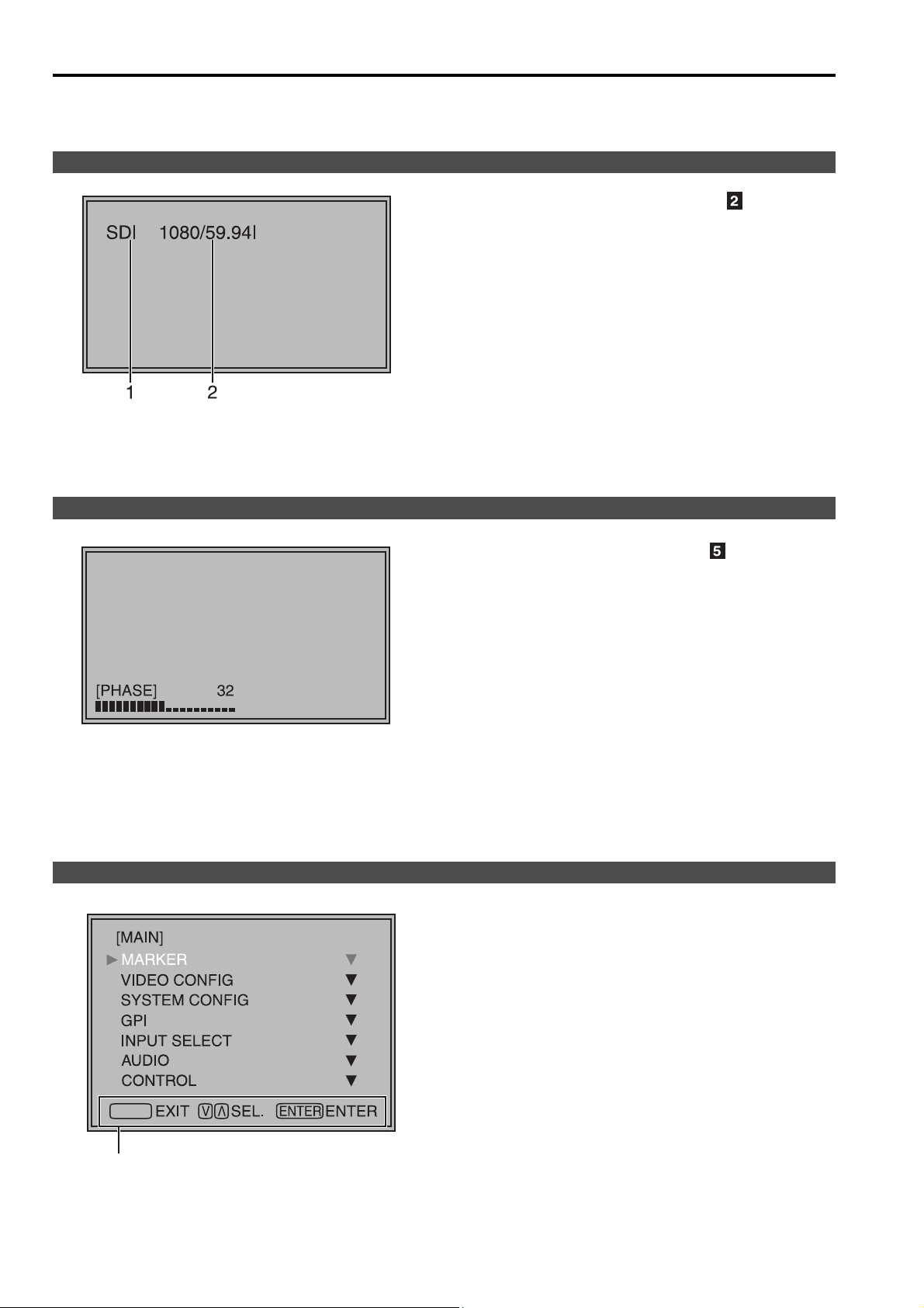
Three types of information are displayed on the screen. The input signal status, picture adjusting knob status, and
the menu display.
Input signal status
1. The selected input line (J page 7, )
1
• VIDEO, Y/C, SDI1, SDI2,
YP
BPR/RGB-VIDEO/RGB-COMP.
2. Signal format
• The display status can be set in “STATUS
DISPLAY” in the “SYSTEM CONFIG” menu
(J page 18).
• If “UNSUPPORT SIGNAL” is displayed, then either
the current input signal is not supported or the
“INPUT SELECT” menu setting needs to be
changed.
• When “NO SIGNAL” is displayed, there is no input
signal.
Note:
“UNSUPPORT SIGNAL” and “NO SIGNAL” may not be
displayed correctly.
Picture adjusting knob status
Menu display
Picture adjusting knob (J page 7, )
• This knob can be rotated and pushed.
• The status display appears when the knob is
pushed.
The display disappears when the knob is pushed
again, or if the knob is not operated for 10 seconds.
• Settings can only be adjusted in the status display.
• The display position can be changed (J page 18
“ROTARY POSITION”).
Status display:
PHASE, CHROMA, BRIGHT, CONTRAST
Note:
The volume knob status display is not displayed on the
screen.
• This is displayed when the menu is used.
• The display disappears if remains idle for 2 minutes.
• The display position can be changed (J page 18
“MENU POSITION”).
MENU
Displays the operation explanation for the
menu button.
10
Page 3
How to Use the On Screen Menu (continued)
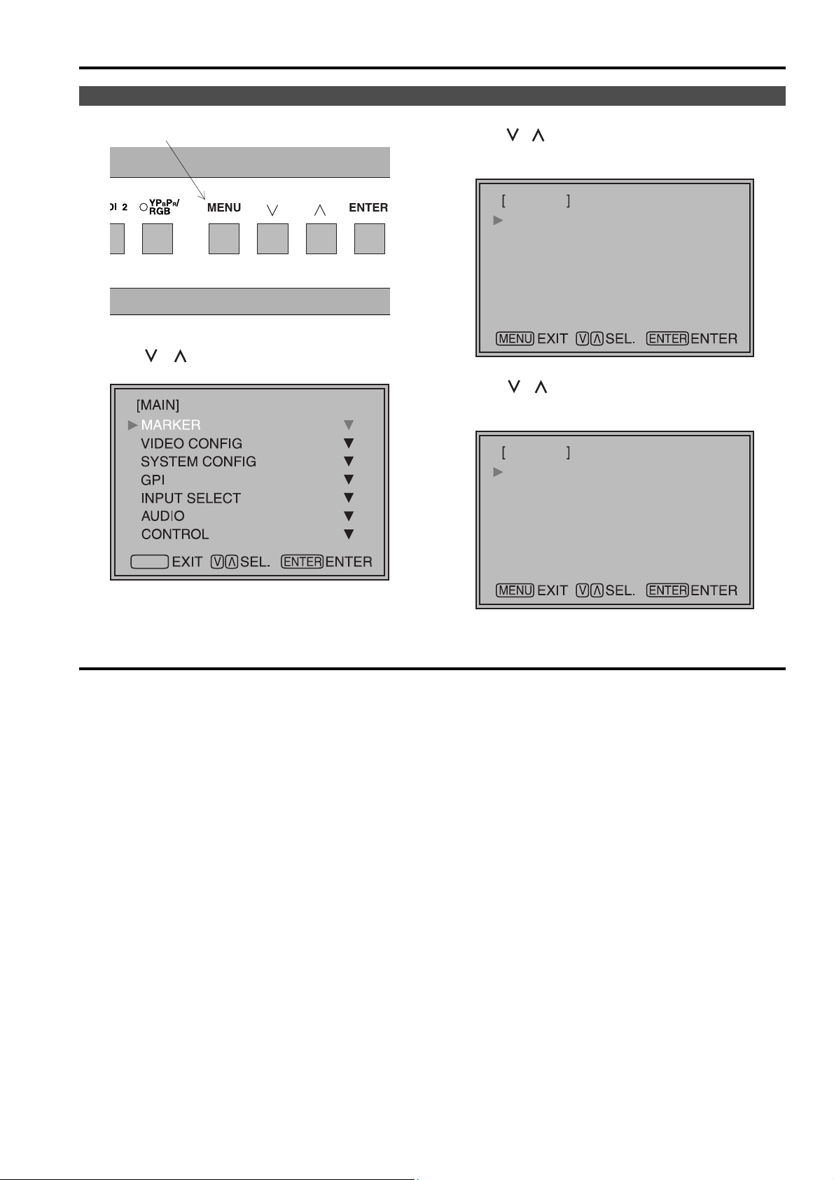
Menu operations
1. Push [MENU] to display the MAIN menu.
2. Push [ , ] to select the menu, then push
[ENTER].
MENU
3. Push [ , ] to select the sub menu, then push
[ENTER].
The setting values in the sub menu change to green.
MARKER
MARKER 16:9
MARKER 4:3
MARKER BACK
CENTER MARKER
GPI PRESET1
GPI PRESET2
4. Push [ , ] to select the setting values, then
push [ENTER].
Push [MENU] to cancel.
MARKER
MARKER 16:9
MARKER 4:3
MARKER BACK
CENTER MARKER
GPI PRESET1
GPI PRESET2
OFF
OFF
NORMAL
OFF
80%
80%
OFF
OFF
NORMAL
OFF
80%
80%
To return to the previous screen
Push [MENU].
11
Page 4
User Data
You can change the menu setting values and picture adjusting knob settings, then save and load up to 5
combinations of screen adjustment values as user data. You can also return the setting values and adjustment
values to the factory preset settings.
The following settings are included in user data.
• Menu settings except for “SETUP LOAD/SAVE” (including the button function settings on the front of the monitor)
• Screen adjustment values changed in picture adjusting knob
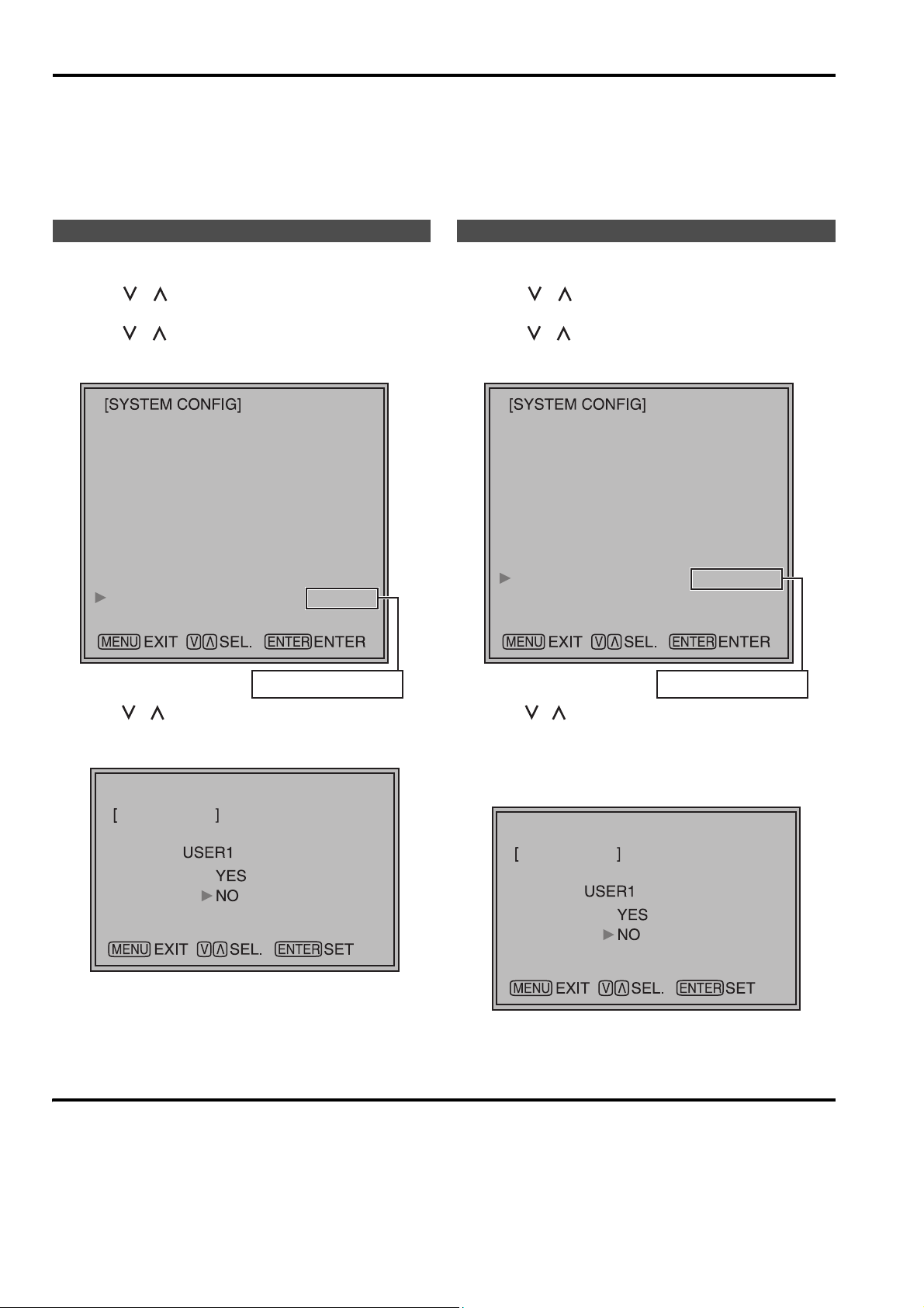
Saving user data
1. Push [MENU] to display the MAIN menu.
2. Push [ , ] to select the “SYSTEM CONFIG”
menu and push [ENTER].
3. Push [ , ] to select the “SETUP SAVE” sub
menu and push [ENTER].
The setting values in the sub menu change to green.
BACKLIGHT
FUNCTION1
FUNCTION2
SUB WINDOW
WFM POSITION
MENU POSITION
ROTARY POSITION
STATUS DISPLAY
SETUP LOAD
SETUP SAVE
FAN MOTOR
SUB WINDOW
HV DELAY
3SEC OFF
FACTORY
60
FULL
RB
CENTER
LB
USER1
OFF
Loading user data
1. Push [MENU] to display the MAIN menu.
2. Push [ , ] to select the “SYSTEM CONFIG”
menu and push [ENTER].
3. Push [ , ] to select the “SETUP LOAD” sub
menu and push [ENTER].
The setting values in the sub menu change to green.
BACKLIGHT
FUNCTION1
FUNCTION2
SUB WINDOW
WFM POSITION
MENU POSITION
ROTARY POSITION
STATUS DISPLAY
SETUP LOAD
SETUP SAVE
FAN MOTOR
SUB WINDOW
HV DELAY
3SEC OFF
FACTORY
60
FULL
RB
CENTER
LB
USER1
OFF
Changes to green
4. Push [ , ] to select the file you wish to save
to from “USER1” – “USER5”, then push [ENTER].
The following screen appears.
SETUP SAVE
5. Select “YES”, and push [ENTER].
The user data is saved.
To return to the previous screen
Push [MENU].
Changes to green
4. Push [ , ] to select the file you wish to load to
from “USER1” – “USER5”, then push [ENTER].
The following screen appears.
To return to the factory preset setting values, select
“FACTORY”.
SETUP LOAD
5. Select “YES”, and push [ENTER].
The user data is loaded.
12
Page 5

Main Menu
Menu configuration
MAIN
MARKER
VIDEO CONFIG
SYSTEM CONFIG
GPI
BACKLIGHT
FUNCTION1
FUNCTION2
SUB WINDOW
WFM POSITION
MENU POSITION
ROTARY POSITION
STATUS DISPLAY
SETUP LOAD
SETUP SAVE
FAN MOTOR
GAMMA SELECT
FILM GAMMA
COLOR TEMP.
SHARPNESS MODE
SHARPNESS H
SHARPNESS V
I-P MODE
MONO
ANAMO
SD ASPECT
SCAN
NOISE WIPE
MARKER 16:9
MARKER 4:3
MARKER BACK
CENTER MARKER
GPI PRESET1
GPI PRESET2
GPI CONTROL
GPI1
INPUT SELECT
AUDIO
CONTROL
VIDEO/ Y/C
NTSC SETUP
YP
BPR
/RGB
COMPONENT LEVEL
RGB SYNC
COMP.
INPUT SELECT
EMBEDDED SELECT L
EMBEDDED SELECT R
CONTROL
LOCAL ENA
*[WHITE BALANCE VAR1-3]
AUTOSETUP
H POSITION
V POSITION
PHASE
CLOCK
WXGA/XGA
GPI2
GPI3
GPI4
GPI5
GPI6
GPI7
GPI8
13
Page 6

Main Menu (continued)
MARKER
The underlined values are factory preset setting values.
Sub menu Settings Explanation
MARKER 16:9
MARKER 4:3
MARKER BACK
CENTER MARKER
GPI PRESET1
GPI PRESET2
*1 When controlling the marker settings using the GPI function (J page 23), these settings become disabled.
These are not operated when the 2 screens are displayed.
*2 These are only enabled when the HD signal and SD signal aspect ratio settings are 16:9.
*3 These are only enabled when the SD signal aspect ratio setting is 4:3.
*1*2
*1*3
*1
*1
<OFF>
<4:3 >
<13:9>
<14:9>
<CNSCO>
<VISTA>
<95%>
<93%>
<90%>
<88%>
<80%>
<OFF>
<95%>
<93%>
<90%>
<88%>
<80%>
<
NORMAL
<HALF>
<BLACK>
<OFF>
<ON>
<4:3 >
<13:9>
<14:9>
<CNSCO>
<VISTA>
<95%>
<93%>
<90%>
<88%>
<80%>
<4:3 >
<13:9>
<14:9>
<CNSCO>
<VISTA>
<95%>
<93%>
<90%>
<88%>
<80%>
>
Used to select/display the type of marker when the aspect ratio
setting is 16:9.
<OFF> Marker not displayed.
<4:3> 4:3 marker
<14:9> 14:9 marker
<VISTA> VISTA marker
<93%> 93%
<88%> 88%
Used to select/display the type of marker when the aspect ratio
setting is 4:3.
<OFF> Marker not displayed.
<95%> 95%
<90%> 90%
<80%> 80%
Used to select the background brightness excluding the marker.
<
NORMAL
<HALF> Background brightness 50%
<BLACK> Background brightness 0% (Black)
Used to display the center marker.
<OFF> Not displayed
<ON> Displayed
Used to select the marker to be displayed using the GPI terminal
“MARKER1 ON/OFF” operation (J page 23).
<4:3> 4:3 marker
<14:9> 14:9 marker
<VISTA> VISTA marker
<93%> 93%
<88%> 88%
Used to select the marker to be displayed using the GPI terminal
“MARKER2 ON/OFF” operation (J page 23).
<4:3> 4:3 marker
<14:9> 14:9 marker
<VISTA> VISTA marker
<93%> 93%
<88%> 88%
Area marker
Area marker
Area marker
Area marker
Area marker
> Normal background
Area marker
Area marker
Area marker
Area marker
<13:9> 13:9 marker
<
CNSCO
> CNSCO marker
<95%> 95%
<90%> 90%
<80%> 80%
<93%> 93%
<88%> 88%
<13:9> 13:9 marker
<
CNSCO
> CNSCO marker
<95%> 95%
<90%> 90%
<80%> 80%
<13:9> 13:9 marker
<
CNSCO
> CNSCO marker
<95%> 95%
<90%> 90%
<80%> 80%
Area marker
Area marker
Area marker
Area marker
Area marker
Area marker
Area marker
Area marker
Area marker
Area marker
Area marker
14
Page 7

Main Menu (continued)
Types of MARKER
g 16:9 marker
(Displayed when using HD, or when using SD
with a 16:9 aspect ratio)
The marker is only displayed as a vertical bar. In
addition, the section becomes the “MARKER
BACK” item.
4:3 marker 13:9 marker
14:9 marker
VISTA marker, CNSCO marker
A horizontal dotted line is displayed as the marker.
Area marker
A dotted line is displayed as the marker.
95% Area marker 93% Area marker
90% Area marker 88% Area marker
80% Area marker
g 4:3 marker
(Displayed when using SD with a 4:3 aspect
ratio)
A dotted line is displayed as the marker.
VISTA marker CNSCO marker
When “UNDER” is set in “SCAN” in the
“VIDEO CONFIG” menu, a vertical dotted line is also
displayed as the marker.
VISTA marker CNSCO marker
95% Area marker 93% Area marker
90% Area marker 88% Area marker
80% Area marker
g Center marker
The marker is displayed in the center of the picture.
Center marker
15
Page 8

Main Menu (continued)
VIDEO CONFIG
The underlined values are factory preset setting values.
Sub menu Settings Explanation
GAMMA
SELECT
FILM GAMMA
*2
*2
COLOR TEMP.
SHARPNESS
MODE
*2
SHARPNESS H
SHARPNESS V
I-P MODE
MONO
ANAMO
SD ASPECT
SCAN
NOISE WIPE
*2
*2
*2
*2
*2
*2
*1 Even if FILM gamma is changed during 2 screen display, only the main window is set, and the changes are not
reflected in the sub window.
*2 When “RGB-COMP.” is selected in “YP
*3 The following sharpness values can each be set,
1) VIDEO system input line (VIDEO,Y/C)(Factory settings are SHARPNESS MODE : LOW,
SHARPNESS H/V : 0)
2) any other input line’s HD (Factory settings are SHARPNESS MODE : HIGH, SHARPNESS H/V : 0)
3) any other input line’s SD (Factory settings are SHARPNESS MODE : LOW, SHARPNESS H/V : 0)
and the setting values for the selected input signal from within this group is displayed. The adjustment status is
displayed in the bottom right when selected.
*4 When “VAR1”, “VAR2” or “VAR3” is selected, the monitor switches to WB adjustment mode (
*5 When selecting USER0–63
1) Push [ENTER] (USER changes to blue). 2) Select 0–63 with [ , ], and push [ENTER].
<NORMAL>
<FILM>
<VARICAM>
<OTHER>
<USER0–63>
<D93>
<D65>
<D56>
<VAR1>
<VAR2>
<VAR3>
<HIGH>
<LOW>
*2
<0–30>
*2
<0–30>
<MODE2>
<MODE1>
<OFF>
<ON>
<OFF>
<ON>
<4:3>
<16:9>
<NORMAL>
<UNDER>
<OFF>
<ON>
*1
Used to select the gamma curve.
When FILM is selected, mark is displayed in the top
left of the screen.
Used to select the type of FILM gamma mode.
<VARICAM> VARICAM use
<OTHER> When using other types than VARICAM
*5
Used to select the color temperature.
<USER0–63> Adjustable settings 0–63 (color temperature
around 3000K–9300K)
<D93> Color temperature around 9300K
<D65> Color temperature around 6500K
<D56> Color temperature around 5600K
<VAR1> WB adjustment mode
<VAR2> WB adjustment mode
<VAR3> WB adjustment mode
*3
Used to select the width of the sharpness edge.
*4
*4
*4
<HIGH> Thin edge <LOW> Thick edge
*3
Used to set the sharpness in the horizontal direction.
When adjusting, the item display moves to the lower part of the
screen.
*3
Used to set the sharpness in the vertical direction.
When adjusting, the item display moves to the lower part of the
screen.
Used to set the mode for IP change.
<MODE2> Within Field <MODE1> Normal mode
Used to switch between color and monochrome (MONO).
<OFF> Color <ON> Monochrome
* When this is ON, the picture adjusting knob [CHROMA] setting
is fixed at 0.
If an Anamo lens has been used on the camera, and input through
SDI 720/60P, 59.94P, the picture is resized to Anamo size
magnification. (a vertically compressed signal can be amplified
vertically and corrected when it is displayed.)
Used for setting the aspect ratio settings when using SD signal
input.
<4:3> 4:3 display <16:9> 16:9 display
Used to set under-scan and normal display.
<NORMAL>Normal display <UNDER>Under-scan
<OFF> This makes a fluid and smooth contrast obtainable.
This is especially effective for continuously changing the contrast
of the source signal or CG signal when the S/N is very high.
<ON> Noise reduction mode. Depending on the camera, this mode
can be especially effective for dark scenes. We recommend
leaving this setting “ON” under normal conditions.
BPR
/RGB” in the “INPUT SELECT” menu (J page 21), this does not operate.
J
page 17).
16
Page 9

Main Menu (continued)
g WB adjustment mode
You can adjust “WHITE BALANCE VAR1” – “WHITE BALANCE VAR3” (WB) by selecting “VAR1” – “VAR3” in
“COLOR TEMP.” in the “VIDEO CONFIG” menu.
The underlined values are factory preset setting values.
Sub menu Settings Explanation
COLOR TEMP.
<USER0–63>
<D93>
<D65>
<D56>
WB-HIGH RED
WB-HIGH GREEN
<0–60>
(Factory preset settings: 30)
WB-HIGH BLUE
WB-LOW RED
WB-LOW GREEN
WB-LOW BLUE
RESET
*1 When adjusting, the item display moves to the lower part of the screen.
Used to select the color temperature that will become the
basis for adjustments.
<USER0–63>
Adjustable settings 0–63 (color
temperature around 3000K–9300K)
<D93> Color temperature around 9300K
<D65> Color temperature around 6500K
<D56> Color temperature around 5600K
Used to adjust the WB in the HIGH level R component.
Used to adjust the WB in the HIGH level G component.
Used to adjust the WB in the HIGH level B component.
Used to adjust the WB in the LOW level R component.
Used to adjust the WB in the LOW level G component.
Used to adjust the WB in the LOW level B component.
This returns the “WB-HIGH RED” – ”WB-LOW BLUE”
settings to the factory presets.
*1
*1
*1
*1
*1
*1
SYSTEM CONFIG
Sub menu Settings Explanation
BACKLIGHT
FUNCTION1
FUNCTION2
< 0–60
> Used to adjust the brightness of the liquid crystal backlight.
<HV DELAY>
<AUTOSETUP>
<BLUE ONLY>
<GAMMA
SELECT>
<SD ASPECT>
<SCAN>
<SUB
WINDOW>
<UNDEF>
<HV DELAY>
<AUTOSETUP>
<BLUE ONLY>
<GAMMA
SELECT>
<SD ASPECT>
<SCAN>
<SUB
WINDOW>
<UNDEF>
Used to select the functions assigned to [FUNCTION1] and
[FUNCTION2] (front buttons).
<HV DELAY>
Displays the synchronizing signal (horizontal, vertical).
The display is switched in the following order.
OFF J H-Delay J V-Delay J HV-Delay J OFF
<AUTOSETUP>
Used to automatically adjust the PC display.
<BLUE ONLY>
Used to cut the red and green signals. You can check the hue (PHASE)
and depth of color (CHROMA). This is switched between ON/OFF by
pushing the button.
<GAMMA SELECT>
You can switch between “NORMAL” and “FILM”.
<SD ASPECT>
Used to switch between “16:9” and “4:3”.
<SCAN>
You can switch between “UNDER” and “NORMAL”.
<SUB WINDOW>
You can perform the settings for 2 screen display mode.
<UNDEF>
No settings
The underlined values are factory preset setting values.
*2
*5
*3*4
*3*4
*3*4
*3*4*6
*2 This function is disabled while in 2 screen display mode.
*3 These functions are disabled when the control settings are in GPI mode.
*4 If these settings are changed, the menu settings will also change.
*5 When “RGB-COMP.” is not selected in “YP
BPR/RGB” in the “INPUT SELECT” menu, “NOT RGB-COMP.CH-” is
displayed, and this does not operate.
*6 This function will not work when “RGB-COMP.” is selected in “YP
BPR/RGB” in the “INPUT SELECT” menu.
17
Page 10

Main Menu (continued)
SYSTEM CONFIG
Sub menu Settings Explanation
SUB WINDOW
WFM POSITION
MENU
POSITION
ROTARY
POSITION
STATUS DISPLAY
SETUP LOAD
SETUP SAVE
FAN MOTO R
<FULL>
<PART>
<WFM>
<LB>
<RB>
<RT>
<LT>
<CENTER>
<LB>
<RB>
<RT>
<LT>
<CENTER>
<LB>
<RB>
<RT>
<LT>
<CONTINUE>
<3SEC OFF>
<OFF>
<FACTORY>
<USER1>
<USER2>
<USER3>
<USER4>
<USER5>
*1
*1
*1
*1
*1
<USER1>
<USER2>
<USER3>
<USER4>
<USER5>
<OFF>
<ON>
Used to select the type of sub window.
<FULL>
Used to reduce the whole input signal screen, and arrange it
horizontally when it is displayed.
<PART>
Used to cut out the central section of the input signal screen, and
arrange it horizontally when it is displayed (Displayed at the same size
as the previous screen).
<WFM>
Used to display the waveform display screen.
Used to set the WFM display position.
<LB> Bottom left of the screen <RB> Bottom right of the screen
<RT> Top right of the screen <LT> Top left of the screen
Used to set the on screen menu display position.
<CENTER> Center of the screen
<LB> Bottom left of the screen <RB> Bottom right of the screen
<RT> Top right of the screen <LT> Top left of the screen
Used to set the picture adjusting knob status (on screen menu) display
position.
<CENTER> Center of the screen
<LB> Bottom left of the screen <RB> Bottom right of the screen
<RT> Top right of the screen <LT> Top left of the screen
Used to set the input signal status (on screen menu) display status.
<CONTINUE> Displayed normally.
<3SEC OFF> After changing status, it is displayed for approximately
<OFF> Not displayed.
The saved factory preset setting values (FACTORY) or the user data
(USER 1–USER 5) are loaded. Also after loading user data, the screen
displays the signal selected before loading data.
Up to 5 sets of user data can be saved (J page 12).
The menu settings and picture adjusting knob adjustment values
(PHASE /CHROMA /BRIGHT /CONTRAST) excluding “SETUP SAVE/
SETUP LOAD” are saved.
Used to set fan operation.
<OFF> The fan is stopped. The brightness of the backlight
<ON> The fan operates. The backlight brightness returns to
The underlined values are factory preset setting values.
*2
3 seconds, and then disappears.
automatically lowers.
normal.
*1 When the monitor is shipped from the factory, “USER1” – “USER5” and “FACTORY” all have the same details.
*2 This screen is not displayed when “RGB-COMP.” is selected in the “YP
BPR/RGB” menu in the “INPUT SELECT”
menu.
g About H/V DELAY
This displays the video blanking period. By pushing the button, you can switch through the H blanking display J
V blanking display J H and V blanking display J no blanking display.
18
Page 11

P
P
P
P
P
Main Menu (continued)
g About the SUB WINDOW
You can compare saved still and moving images or show the Wave Form Monitor (WFM) by using the “SUB
WINDOW” function to separate the main window into 2 displays as shown below.
Depending on the settings of the “SUB WINDOW” (FULL, PART, WFM) in the “SYSTEM CONFIG” menu
(J page 18) it can be switched as shown below.
Every time you press the [FUNCTION1] (or [FUNCTION2]) button (J page 17) assigned to the “SUB WINDOW”
function, the window switches (To use the “SUB WINDOW” function, assign it to [FUNCTION1] or
[FUNCTION2]).
•FULL
The main window is reduced and made into 2 sub window (sub window+sub window).
Press [FUNCTION1] or [FUNCTION2] once
Normal window
(main window)
ress
[FUNCTION1]
or
[FUNCTION2]
once
moving image
Before inputting the image
(sub window+sub window)
moving image moving image
After inputting the image
(sub window+sub window)
ress
[FUNCTION1]
or
[FUNCTION2]
once
still image moving image
•PART
Only the sub window size is cut out of the main window, and the cut section is made into 2 sub window images
(sub window+sub window).
Press [FUNCTION1] or [FUNCTION2] once
Normal window
(main window)
ress
[FUNCTION1]
or
[FUNCTION2]
once
moving image
The central section is cut out Lines up and displays the
Before inputting the image
(sub window+sub window)
ress
[FUNCTION1]
or
[FUNCTION2]
once
moving image moving image
section cut out of the main
After inputting the image
(sub window+sub window)
still image moving image
* Only compatible with
HD signals
window
•WFM
Displays the Wave Form Monitor image
Press [FUNCTION1] or
[FUNCTION2] once
Normal window WFM display
ress
[FUNCTION1]
or
[FUNCTION2]
once
WFM (Wave Form Monitor)
The window is displayed in 16:9 aspect.
Precautions when selecting FULL/PART
This function compares screens with the same input terminal and same format. If different input formats, or if
signals are input between different input channels, the sub-window (left side, still image) becomes blurred and
blanking occurs. However, if the same format signals are input into the input terminal when acquiring the still image,
the images will be displayed correctly.
19
Page 12

Main Menu (continued)
GPI
The “GPI CONTROL” item is used to set enable/disable of all GPI functions, and assigns functions to each of the
GPI terminal pins (J page 23).
The underlined values are factory preset setting values.
Sub menu Settings Explanation
GPI CONTROL
GPI1–GPI8
<DISENABLE>
<ENABLE>
<UNDEF>
<MARKER1 ON/OFF>
<MARKER2 ON/OFF>
<MARKER BACKHALF>
<MARKER BACKBLACK >
<CENTER MARKER>
<INPUT SEL. VIDEO>
<INPUT SEL. Y/C>
<INPUT SEL. SDI1>
<INPUT SEL. SDI2>
<INPUT SEL. YP
<SD ASPECT>
<SCAN>
<R-TALLY>
<G-TALLY>
<MONO>
<GAMMA SELECT>
<RGB SYNC>
BPR/RGB>
GPI functions enable/disenable settings
Used to set the GPI control terminal pin assign.
You can set the same items for each terminal
(refer to page 23 for details).
Note:
Please be aware that the following can not be performed.
• “SD ASPECT” operation when input signal is HD or PC
• “SCAN” operation when the input signal is PC
• “GAMMA SELECT” operation when the input signal is PC
• “RGB SYNC” operation when anything other than “RGB-VIDEO” is selected in “YP
SELECT” menu
• “MONO” operation when input signal is PC
BPR/RGB” in the “INPUT
20
Page 13

Main Menu (continued)
INPUT SELECT
The underlined values are factory preset setting values.
Sub menu Settings Explanation
VIDEO / Y/C
NTSC SETUP
YP
BPR/RGB
COMPONENT
LEVEL
RGB SYNC
COMP.
“AUTO” is set when the monitor is shipped from the factory, but if there are concerns about noise etc. from outside the
*1
input signal, we recommend assigning specific format.
<AUTO>
<NTSC>
<PAL>
<75>
<00>
<YP
BPR>
<RGB-VIDEO>
<RGB-COMP.>
<SMPTE>
<B75>
<B00>
<G-ON>
<EXT>
Used to select the input format for VIDEO and Y/C input.
<AUTO> Either NTSC or PAL is automatically selected.
<NTSC> NTSC <PAL> PAL
Selects the NTSC setup level.
<75> Select this when using with a setup signal of
7.5 IRE. (The inner parts of the monitor are set
to the 7.5 IRE setup level to suit the black level)
<00> Select this when there is no setup level signal.
Selects either YP
<YP
BPR> Selects the YPBPR signal.
<RGB-VIDEO>
<RGB-COMP.>
Selects YP
BPR (Component) or RGB input mode.
Selects the video RGB signal.
Selects the PC RGB signal.
BPR (Component) signal input level.
<SMPTE> When the signal level specified in SMPTE is
Chroma 100 IRE P
B, PR = 0.7 Vp-p.
<B75> Select this when connecting a betacam or
simliar devices set to 7.5 IRE. (The inner parts
of the monitor are set at 7.5
IRE
setup level to
suit the black level)
<B00> Select this when connecting a betacam or similar
devices that are not setup to the IRE level.
Selects the SYNC when using RGB-VIDEO input.
<G-ON> Select when a synchronizing signal is
superimposed on the G signal.
<EXT> Select when an external synchronizing signal is
received in synchronization.
Performs analog PC settings. (Refer to “COMP.” below)
*1
g COMP.
The following menus are switched by selecting “RGB-COMP.” in “YP
The underlined values are factory preset setting values.
BPR/RGB” in the “INPUT SELECT” menu.
Sub menu Settings Explanation
AUTOSETUP *1 Screen automatic adjustment is performed when “RGB-
COMP.” is selected in “YP
BPR/RGB” in the “INPUT SELECT”
menu. “AUTOSETUP” is performed if a different screen is
displayed, and “YES” is selected.
H POSITION
V POSITION
PHASE
<0–60>
(Factory preset settings: 30)
<0–60>
(Factory preset settings: 30)
<0–31>
Used to adjust the picture display position in the horizontal
direction.
Used to adjust the picture display position in the vertical
direction.
Used to adjust the clock phase with 1/32 clock phases.
*2
*2
*2
(Factory preset settings:
J page 22)
CLOCK
<700–1800>
Used to adjust the sampling clock in dot units.
*2
(Factory preset settings:
J page 22)
WXGA/XGA
<XGA>
Switches between WXGA and XGA.
<WXGA>
*1 “EXECUTING” is displayed while “AUTOSETUP” is being executed, and “COMPLETE” is displayed when
“AUTOSETUP” is completed.
If “AUTOSETUP” cannot be completed, “INCOMPLETE” is displayed.
*2 Each RGB-COMP. input compatible format can be adjusted.
21
Page 14

Main Menu (continued)
g “PHASE” and “CLOCK” factory preset setting values
FORMAT CLOCK PHASE FORMAT CLOCK PHASE
640x400(70Hz) 800 18 1024x768(60Hz) 1344 2
640x480(60Hz) 800 17 1024x768(70Hz) 1328 22
640x480(75Hz) 840 10 1024x768(75Hz) 1312 16
640x480(85Hz) 832 5 1024x768(85Hz) 1376 17
800x600(60Hz) 1056 31 1280x768(60Hz) 1728 8
800x600(75Hz) 1056 12 1280x768(75Hz) 1712 31
800x600(85Hz) 1048 29 1280x1024(60Hz) 1688 20
AUDIO
Adjusting the speaker output. This can only be set when the monitor is equipped with an embedded audio unit BTYAE1700G (optional). If the monitor is not equipped with an embedded audio unit, the output will be in analog.
The underlined values are factory preset setting values.
Sub menu Settings Explanation
INPUT
SELECT
EMBEDDED
SELECT L
EMBEDDED
SELECT R
<AUTO>
<ANALOG>
<EMBEDDED>
<CH1–CH8>
(Factory preset
settings: CH1)
<CH1–CH8>
(Factory preset
settings: CH2)
Used to select speaker output.
<AUTO> When SDI input line is selected (front panel) :
embedded audio (SDI terminal)
When any other line than SDI input line is selected
analog (AUDIO input terminal)
<ANALOG> Analog (AUDIO input terminal)
<EMBEDDED>
Used to select the audio channel of the embedded audio outputted to the left
speaker.
Used to select the audio channel of the embedded audio outputted to the
right speaker.
When SDI input line is selected (front panel) :
embedded audio (SDI terminal)
When any other line than SDI input line is selected (front panel) :
No sound
(front panel)
:
CONTROL
The underlined values are factory preset setting values.
Sub menu Settings Explanation
CONTROL
LOCAL
*2
ENA
*1 The menu can be displayed when the lock is engaged.
The only menu setting that can be changed when the lock is engaged is the “CONTROL/LOCAL ENA” item.
When the lock is engaged, the picture adjusting knob is disabled.
Operations when the lock is engaged follow the settings in “LOCAL ENA”.
When the lock is engaged, the volume knob can be operated (J page 7, ).
When the lock is engaged, the key mark is displayed on the screen.
MARKER
*2 This is only enabled when “CONTROL” is set to “REMOTE”.
<LOCAL>
<REMOTE>
<DIS.>
<INPUT>
Used to select the operation. (Combined control lock)
<LOCAL> Front operation enabled
<REMOTE>
When “REMOTE” is selected in “CONTROL”, this selects whether front
controls are enabled/disenabled.
<DIS.>
<INPUT> All controls except for the [INPUT SELECT] button and
Remote operation enabled (The front controls become locked)
A
ll front operations are disabled.
volume knob are disabled.
Key mark
*1
22
 Loading...