

Panasonic bt-lh900a, bt-lh900 operating instructions
Liquid Crystal Video Monitor
POWER
INPUT MENU
EXIT
ENTER
HD ZOOM BLUE
FUNCTION
PEAK/PHASE CHROMA BRIGHT CONTRAST
BT-LH900
P
S0903T5025-F @
Printed in Japan
Before attempting to connect, operate or adjust this product, please read these instructions completely.
ENGLISH
VQT0F30-2
For your safety
Ni-Cd
RBRC
RBRC
CAUTION
RISK OF ELECTRIC SHOCK
DO NOT OPEN
CAUTION: TO REDUCE THE RISK OF ELECTRIC SHOCK,
DO NOT REMOVE COVER (OR BACK).
REFER TO SERVICING TO QUALIFIED SERVICE PERSONNEL.
NO USER SERVICEABLE PARTS INSIDE.
The lightning flash with arrowhead symbol,
within an equilateral triangle, is intended to
alert the user to the presence of uninsulated
“dangerous voltage” within the product’s
enclosure that may be of sufficient magnitude
to constitute a risk of electric shock to
persons.
The exclamation point within an equilateral
triangle is intended to alert the user to the
presence of important operating and
maintenance (service) instructions in the
literature accompanying the appliance.
WARNING:
• TO REDUCE THE RISK OF FIRE OR SHOCK
HAZARD, DO NOT EXPOSE THIS EQUIPMENT TO
RAIN OR MOISTURE.
• TO REDUCE THE RISK OF FIRE OR SHOCK
HAZARD, KEEP THIS EQUIPMENT AWAY FROM
ALL LIQUIDS. USE AND STORE ONLY IN
LOCATIONS WHICH ARE NOT EXPOSED TO THE
RISK OF DRIPPING OR SPLASHING LIQUIDS,
AND DO NOT PLACE ANY LIQUID CONTAINERS
ON TOP OF THE EQUIPMENT.
CAUTION:
TO REDUCE THE RISK OF FIRE OR SHOCK
HAZARD AND ANNOYING INTERFERENCE, USE
THE RECOMMENDED ACCESSORIES ONLY.
FCC Note:
This equipment has been tested and found to comply
with the limits for a class A digital device, pursuant to
Part 15 of the FCC Rules. These limits are designed
to provide reasonable protection against harmful
interference when the equipment is operated in a
commercial environment. This equipment generates,
uses, and can radiate radio frequency energy, and if
not installed and used in accordance with the
instruction manual, may cause harmful interference to
radio communications. Operation of this equipment in
a residential area is likely to cause harmful
interference in which case the user will be required to
correct the interference at his own expense.
Warning:
To assure continued FCC emission limit compliance,
the user must use only shielded interface cables when
connecting to external units. Also, any unauthorized
changes or modifications to this equipment could void
the user’s authority to operate it.
Notice (U.S.A. only):
This product has a fluorescent lamp that contains
a small amount of mercury. It also contains lead
in some components. Disposal of these materials
may be regulated in your community due to
environmental considerations. For disposal or
recycling information, please contact your local
authorities, or the Electronics Industries Alliance:
<http://www.eiae.org.>
CAUTION:
In order to maintain adequate ventilation, do not
install or place this unit in a bookcase, built-in
cabinet or any other confined space. To prevent
risk of electric shock or fire hazard due to
overheating, ensure that curtains and any other
materials do not obstruct the ventilation.
ATTENTION:
The product you have purchased is powered by a
nickel cadmium battery which is recyclable. At the
end of it’s useful life, under various state and local
laws, it is illegal to dispose of this battery into your
municipal waste stream.
Please call 1-800-8-BATTERY for information on how
to recycle this battery.
indicates safety information.
2

Contents
Precautions for use . . . . . . . . . . . . . . . 3
Introduction . . . . . . . . . . . . . . . . . . . . . . 4
Parts and their functions . . . . . . . . . . . 5
Relocating the main controls . . . . . . . 8
Supplying the power . . . . . . . . . . . . . . 9
Cosmetic screws . . . . . . . . . . . . . . . . 10
How to use the on-screen menus . . . 11
Menu operations . . . . . . . . . . . . . . . . . 13
User data . . . . . . . . . . . . . . . . . . . . . . . 14
MAIN MENU . . . . . . . . . . . . . . . . . . . . . 15
REMOTE specifications . . . . . . . . . . . 22
Error and warning displays . . . . . . . . 23
Maintenance and inspections . . . . . . 24
Specifications . . . . . . . . . . . . . . . . . . . 25
Precautions for use
This product has been specially designed for commercial use. As such, it should be used and operated
only by persons with related expertise.
¥ The liquid crystal parts are fabricated using high-precision technology. The screen has effective pixels that cover
more than 99.99% of its area, but pixels may be missing or remain permanently lighted (red, blue and/or green) in
less than 0.01% of the area. This is not indicative of malfunctioning.
¥ The panel which protects the liquid crystal display has been specially treated.
Do not wipe it with hard cloths or rub it heavily as this will damage the surface of the panel.
¥ If a still image is displayed continuously for a long period of time, the image may be burnt onto the screen for
some time. (The shadow of the image will usually disappear after moving images are displayed for while.)
¥ The response speed and brightness of the liquid crystals will vary with the surrounding temperature.
3
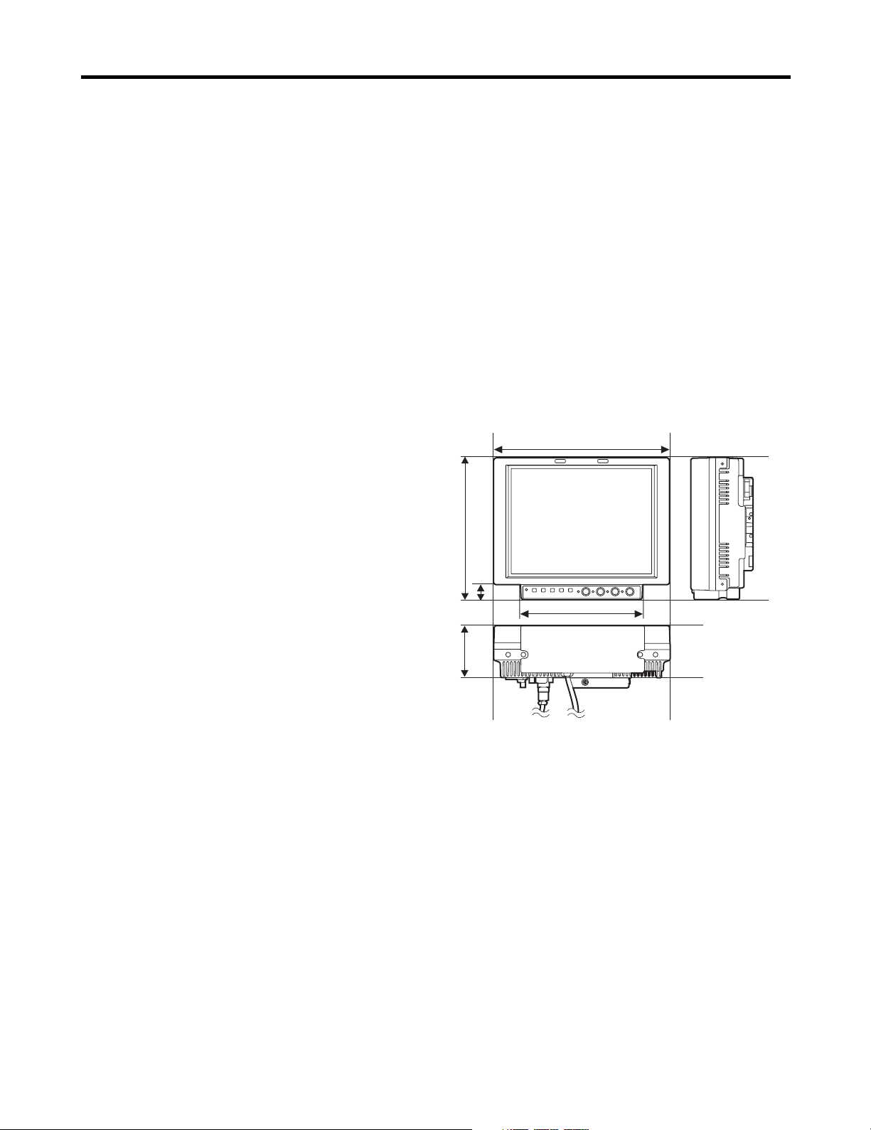
218 mm
176 mm
18 mm
150 mm
65 mm
Introduction
Designed for use in broadcasting and commercial applications, the model BT-LH900P is a slim-line and lightweight liquid
crystal video monitor with an 8.4-type liquid crystal screen.
For use, secure it in place by, for instance, installing it in a rack by using the optional rack-mounting adapters BT-MA900G or
mounting it on a tripod. (For details, refer to the instructions in the operation guide of the BT-MA900G.)
∫ Slim design, light weight, compact size, low
power consumption and driven by DC
power
Since this monitor uses an LCD panel, it has a slim
design, light weight and compact size. Furthermore,
while supporting HD specifications, it has a low power
consumption, and it can be operated using DC power:
these are all features which make the monitor useful in
outdoor locations.
∫ Multiple formats supported
In addition to its two lines of SDI input connectors
(automatic HD/SD switching), the monitor provides one
line each of component input connectors and composite
input connectors.
∫ Wide viewing angle
The monitor can display excellent images over an angle
extending for 170 degrees in both the top-bottom and leftright directions.
∫ High-definition images
At 1024 a 768 dots (XGA), the large number of screen
pixels ensures a high color reproducibility and tonal
range.
∫ Functions
The main controls can be relocated to the bottom surface
or right panel of the main unit to support monitor
specifications, viewfinder specifications and other
applications.
≥ The monitor comes with a film gamma correction
function to support its use as the viewfinder for the AJHDC27F. (For further details, consult with your dealer
or a Panasonic Service Center.)
≥ Waveform monitor functions provided
≥ Marker functions and blue-only function incorporated
≥ RS-232C external control, remote control using GPI
connector enabled
∫ Outline diagrams of monitor as seen from
three sides
4
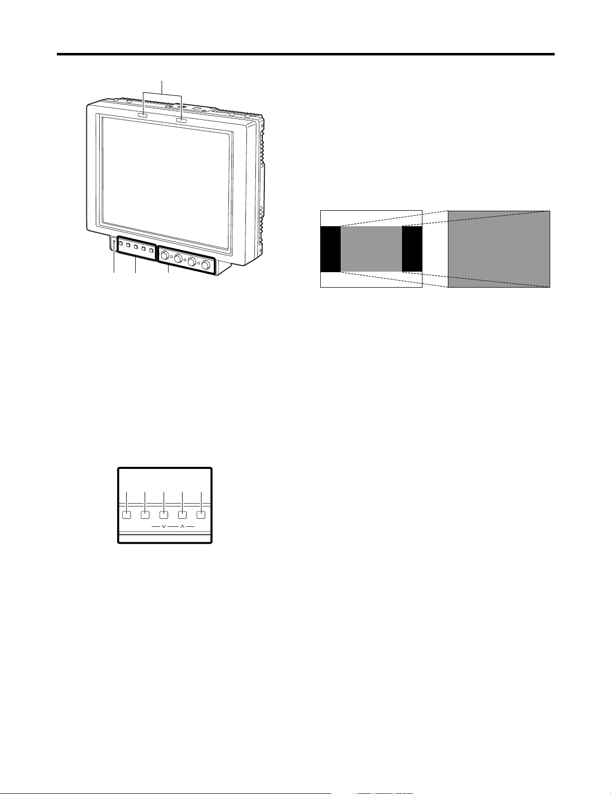
Parts and their functions
3
4
1
2
INPUT MENU
EXIT
ENTER
HD ZOOM BLUE
FUNCTION
1
2 3 4 5
3
HD ZOOM/XXbutton
This button is used to move the cursor or change
settings while a menu is displayed.
If there is no menu display, it turns the HD ZOOM
function ON or OFF. When the button is pressed,
both the left and right sides of the images with a 16:9
aspect ratio produced by HD signals are cut off, and
images with a 4:3 aspect ratio are displayed on the
entire screen. When it is pressed, the original images
are restored.
The HD zoom function does not work when images of
SD signals are displayed.
1
Tally lamps
In the above illustration, the R (red) tally lamp is shown
on the left and the G (green) lamp appears on the right.
These tally lamps can be lighted by initiating the GPI
ON/OFF operation.
<Note>
When the monitor is used outdoors, it may be hard to
see that the tally lamps are in fact lighted.
Controls 2, 3 and 4 can be separated from the monitor
main unit as the main controls and relocated to the bottom
surface or right panel of the main unit.
2
Power LED
This is the power LED. It lights while the power is ON.
3
Function buttons
1
INPUT button
This button is used to select the signal input. Each
time it is pressed, the input channels are switched by
one setting in the following sequence: SDI 1 > SDI 2
> VIDEO > YPBPR/RGB.
By means of the INPUT menu settings, the unused
channels can be skipped.
2
MENU/EXIT button
This button is used to display the menus. When it is
pressed while a menu is already displayed, the menu
display is cleared or the menu at one hierarchical level
above is restored.
When the button is pressed while a setting is being
changed, the setting established prior to the change is
restored, and the menu at one hierarchical level
above is restored.
HD ZOOM
4
BLUE/WWbutton
This button is used to move the cursor or change
settings while a menu is displayed.
If there is no menu display, it turns the blue-only
function ON or OFF. When this function is set to ON,
only the blue components among the RGB
components are displayed.
5
Parts and their functions
PEAK/PHASE CHROMA BRIGHT CONTRAST
1
2
3 4
5
FUNCTION/ENTER button
This button is used to enter changes or settings while
a menu is displayed.
If there is no menu display, the button’s function
changes depending on which FUNCTION item on the
menu is selected. One of the following three items
can be selected. (Refer to page 19)
UNDEF: No function is allocated to this item.
HV DELAY
WFM ON/OFF
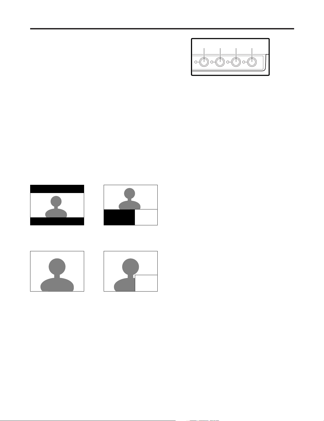
: Image blanking is displayed. Each time
the button is pressed, the blanking
display is switched by one setting in the
following sequence: H blanking display
> V blanking display > H and V
blanking display > no blanking display.
: The Y signal (luminance) waveform is
displayed at the bottom right of the
image. When the button is pressed
again, the display is cleared.
When waveforms are displayed in the
16:9 mode, the image displayed on the
screen moves to the upper part of the
screen so that it will not be
superimposed onto the waveform
display.
>
WFM
WFM function OFF WFM function ON
The image remains unchanged in the 4:3
mode.
>
WFM
WFM function OFF WFM function ON
<Notes>
≥ In order for this function to be used, it is necessary to
select WFM as the FUNCTION item setting on the
SYSTEM CONFIG screen, and then select FUNCTION
as the WFM item setting.
≥ The WFM function is a simplified one and, as such,
finely detailed waveforms may not be displayed
accurately.
In addition, differences in the input signal format or
input function may result in the display having a
different horizontal width.
4
Image controls
These controls are used to adjust the peaking/color
phase, chroma, brightness and contrast. When a control
is pushed in, it pops out to enable adjustment. When a
numerical value is changed from the default setting, the
lamp to the left of the control lights.
The adjustments performed using these controls are
valid only when the controls are in the “out” position, and
when a control is pushed back in, the value adjusted by
that control is returned to its default setting.
1
2
3
4
PEAK/PHASE (PEAKING/PHASE)
This control is used to adjust the peaking or phase.
Which of these is to be adjusted is set using the
PEAKING/PHASE item on the SYSTEM CONFIG
screen.
≥ PEAKING
This function is selected when the monitor is to be
used as a viewfinder.
It is used to set the edge sharpness. Any value
from 0 to 30 can be set: the higher the value, the
sharper the edges. The default setting is 0.
≥ PHASE
This function is selected when the monitor is to be
used as a monitor.
It is used to set the color phase of the screen. Any
value from 0 to 60 can be set. The default setting
is 30.
<Notes>
≥ When the blue-only function is ON, the control
functions as the PHASE control regardless of
the setting.
≥ The color phase cannot be adjusted when RGB
signals are input.
CHROMA
This control is used to adjust the image chroma. Any
value from 0 to 60 can be set. The default setting is
30.
<Note>
The chroma cannot be adjusted when RGB signals
are input or when the MONO setting is ON.
BRIGHT
This control is used to adjust the image brightness.
Any value from 0 to 60 can be set. The default setting
is 30.
However, the brightness cannot be adjusted when
blanking is displayed using the HV DELAY function.
CONTRAST
This control is used to adjust the image contrast. Any
value from 0 to 60 can be set. The default setting is
50.
6
Parts and their functions
Y/G
VIDEO
IN
OUT
SDI 1
IN
SDI 2
IN
SWITCHED
OUT
PB/B
PR/R
SYNC
CONTROL
GPI
RS-232C
POWER
DC IN
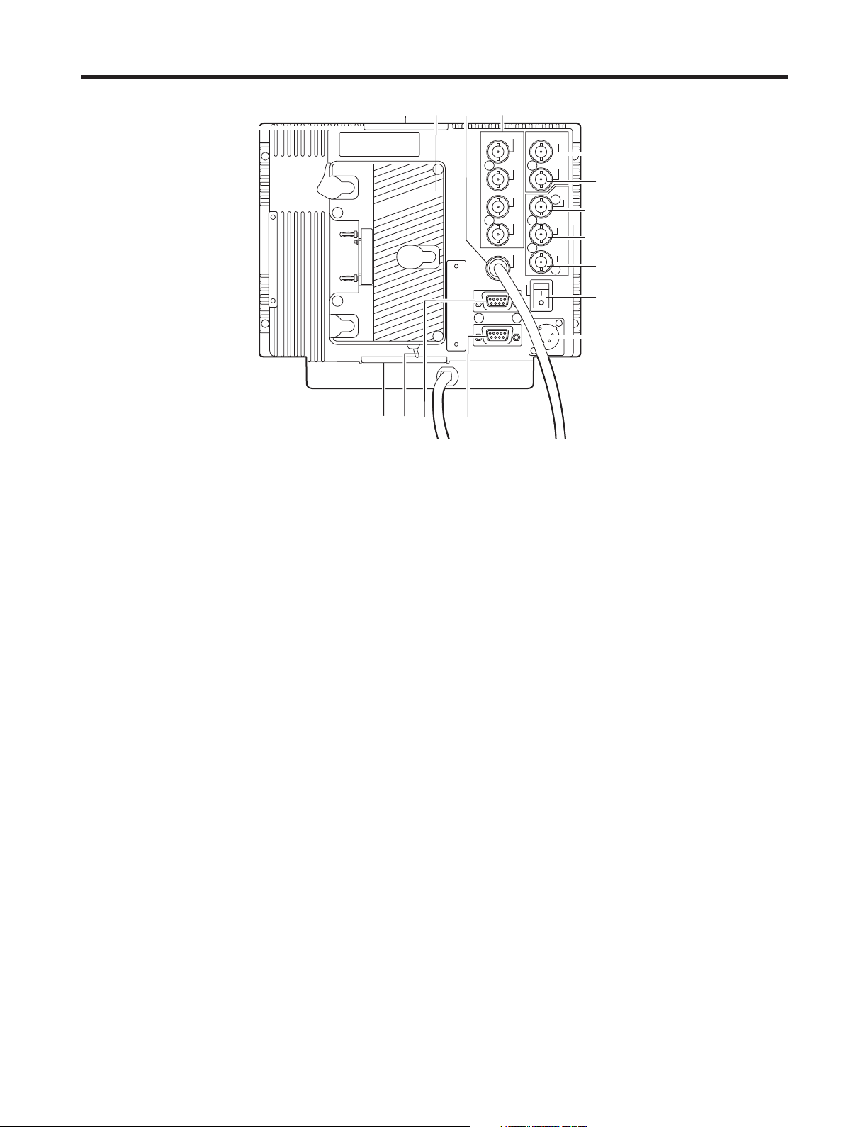
6
7
8
9
:
;
<
=
>
?
5
@
@
A
5
Battery holder
This holder is used with a battery made by Anton Bauer.
6
Analog component/RGBS connectors
These are the BNC input connectors for the analog
component (YPBPR) or RGBS signals. When RGB
signals are supplied, external sync (gen-lock) can also
be used.
7
Main controls dedicated connector
The cable from the main controls is connected here.
<Note>
The monitor is shipped with the cable disconnected from
the connector. Prior to use, therefore, check out the
shape of the cable connector and plug it properly into this
connector.
8
GPI connector
When GPI signals are connected here, external
operations can be performed.
9
RS-232C connector
External operations can be performed under the RS232C standard.
:
VIDEO IN connector
The video input signals are supplied to this connector.
;
VIDEO OUT connector
The video signals are output from this connector.
Signals are passed through the : VIDEO IN connector
and output from this connector.
<
SDI input connectors
The SDI input signals are supplied to these connectors
which support automatic HD/SD switching.
=
SDI output connector
The SDI signals are output from this connector. It is the
switched output of the < SDI input connectors.
The signals displayed on the screen, whether they are
the ones supplied to the SDI 1 connector or SDI 2
connector, are output.
However, the switched output signals are not output
when the component or video input signals have been
selected.
>
Power switch
This is the power switch.
?
External DC power socket
The external DC power source is connected here. When
a DC power supply is connected concurrently with the
battery, the external power input takes precedence.
@
Tripod fastening screws
Two screws (UNC3/8-16 compatible) for securing a
tripod are provided each on the top of the monitor and at
its bottom where the main controls are removed.
A removable screw spacer is provided in one of the
screw holes in the bottom of the monitor, and this
supports a UNC1/4-20 screw. To secure the tripod, use
the hole that fits the diameter of the fastening screw on
the tripod.
A
Light control switch
This is not used on this monitor.
7
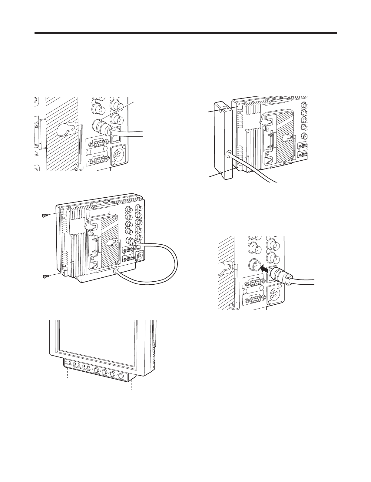
Relocating the main controls
The main controls can be relocated to the bottom surface or right panel of the monitor depending on such factors as where
and how the monitor will be used.
<Note>
Before relocating the main control, make absolutely sure that the power has been turned off.
Disconnect the cord connecting the main controls to the
1
main unit.
Take hold of this part
and pull it free to
disconnect the cable.
Remove the screws on the right panel of the main unit.
2
Use the two screws to secure the main controls to the
4
right panel.
Plug the cord connecting the main controls into the
5
connector on the main unit and secure it.
<Note>
Using too much force to plug in the cord at the wrong
insertion angle may damage the pins inside. Check out
the shape of the connector before plugging it in.
Remove the two screws, and remove the main controls
3
from the main unit. These two screws cannot be
removed from the main controls themselves.
Plug in the connector
until it clicks into place.
Secure the two screws, which were removed in step
6
2,
8
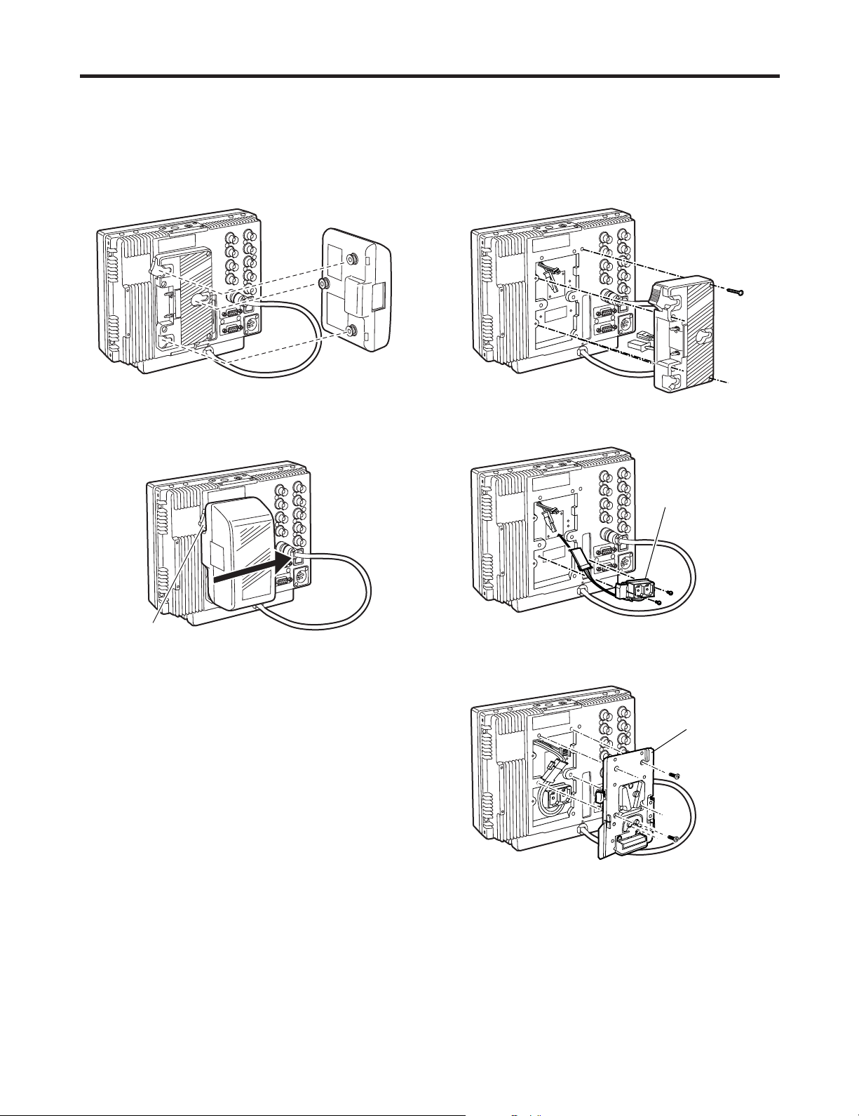
Supplying the power
An Anton Bauer, V-mount or other such type of battery pack or an AC power source can be used to power this monitor.
Using the Anton Bauer battery
pack
Install the Anton Bauer type of battery pack.
1
Battery pack
Insert the battery pack and slide it in the direction of the
2
arrow.
Using a V-mount battery pack
Remove the battery holder.
1
Battery holder
Install the accessory metal battery mount.
2
Metal battery mount
Release lever
<Reference>
To remove the battery pack, slide it in the opposite direction
to the one in which it was attached while keeping the
release lever on the battery holder pulled down all the way.
Secure the V-mount adapter using the four screws, and
3
then secure the two screws of the connector section.
V-mount adapter
9
 Loading...