

Page 1
Operating Instructions
LCD Video Monitor
BT- P
Model No. BT- E
Before operating this product, please read the instructions carefully and save this manual for future use.
S0506M1076 -H
Printed in Japan
D
ENGLISH
VQT0X79-1
Page 2
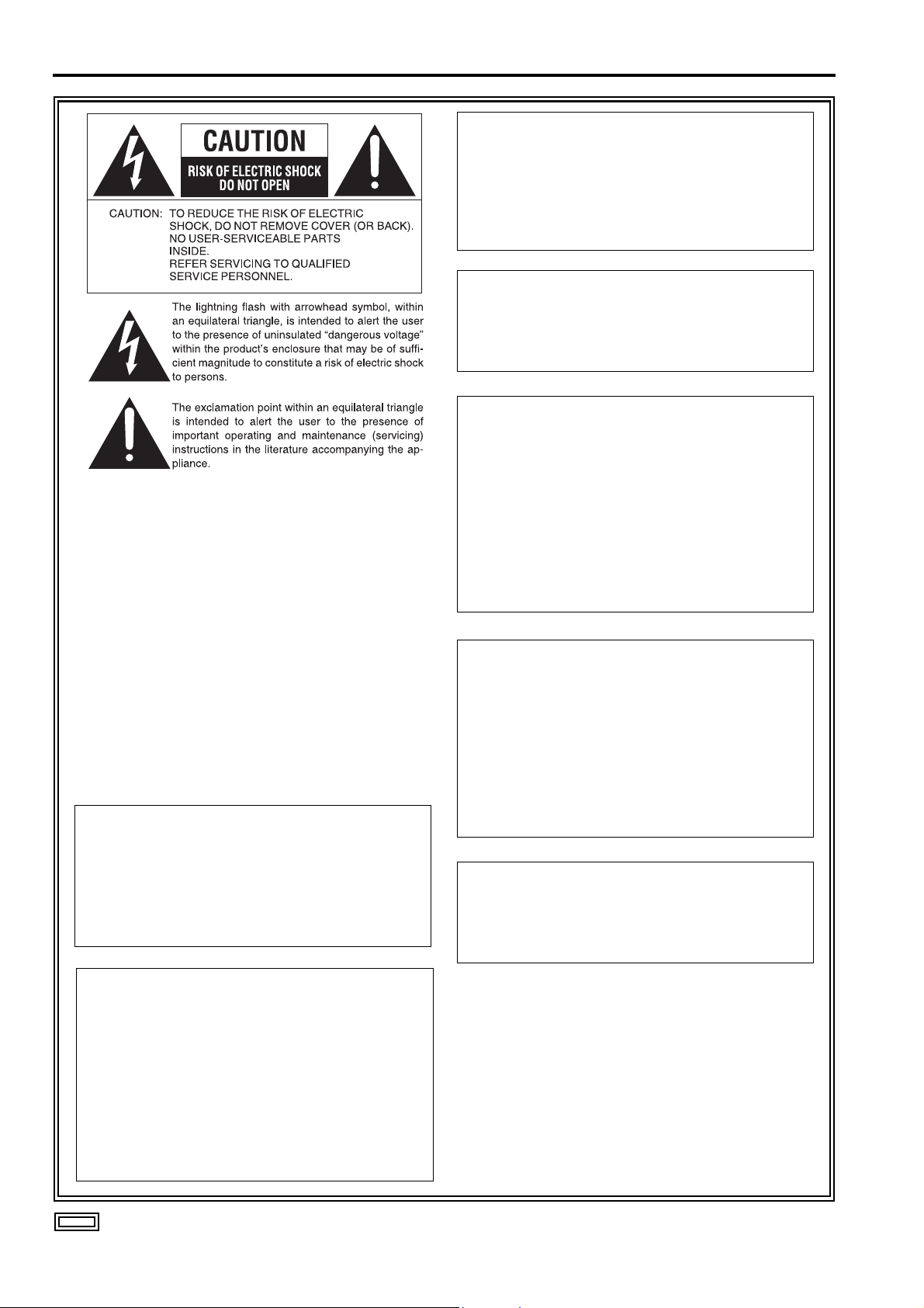
Read this first ! (for BT-LH2600WP)
CAUTION:
In order to maintain adequate ventilation, do
not install or place this unit in a bookcase,
built-in cabinet or any other confined space. To
prevent risk of electric shock or fire hazard due
to overheating, ensure that curtains and any
other materials do not obstruct the ventilation.
CAUTION:
TO REDUCE THE RISK OF FIRE OR SHOCK
HAZARD AND ANNOYING INTERFERENCE,
USE THE RECOMMENDED ACCESSORIES
ONLY.
CAUTION:
This apparatus can be operated at a voltage in the
range of 100 - 240 V AC.
Voltages other than 120 V are not intended for
U.S.A. and Canada.
g THIS EQUIPMENT MUST BE GROUNDED
To ensure safe operation, the three-pin plug must
be inserted only into a standard three-pin power
outlet which is effectively grounded through
normal household wiring. Extension cords used
with the equipment must have three cores and be
correctly wired to provide connection to the
ground. Wrongly wired extension cords are a
major cause of fatalities. The fact that the
equipment operates satisfactorily does not imply
that the power outlet is grounded or that the
installation is completely safe.
For your safety, if you are in any doubt about the
effective grounding of the power outlet, please
consult a qualified electrician.
CAUTION:
THE AC RECEPTACLE (MAINS SOCKET OUTLET)
SHALL BE INSTALLED NEAR THE EQUIPMENT
AND SHALL BE EASILY ACCESSIBLE.
TO COMPLETELY DISCONNECT THIS EQUIPMENT
FROM THE AC MAINS, DISCONNECT THE POWER
CORD PLUG FROM THE AC RECEPTACLE.
CAUTION:
Operation at a voltage other than 120 V AC may
require the use of a different AC plug. Please
contact either a local or foreign Panasonic
authorized service center for assistance in
selecting an alternate AC plug.
Notice (U.S.A. only):
This product has a fluorescent lamp that
contains a small amount of mercury. It also
contains lead in some components. Disposal
of these materials may be regulated in your
community due to environmental
considerations. For disposal or recycling
information please contact your local
authorities, or the Electronics Industries
Alliance: <http://www.eiae.org.>
CAUTION:
• Keep the temperature inside the rack to
between 41°F to 95°F (5°C to 35°C).
• Bolt the rack securely to the floor so that it
will not topple over.
WARNING:
• TO REDUCE THE RISK OF FIRE OR SHOCK
HAZARD, DO NOT EXPOSE THIS
EQUIPMENT TO RAIN OR MOISTURE.
• TO REDUCE THE RISK OF FIRE OR SHOCK
HAZARD, KEEP THIS EQUIPMENT AWAY
FROM ALL LIQUIDS. USE AND STORE ONLY
IN LOCATIONS WHICH ARE NOT EXPOSED
TO THE RISK OF DRIPPING OR SPLASHING
LIQUIDS, AND DO NOT PLACE ANY LIQUID
CONTAINERS ON TOP OF THE EQUIPMENT.
indicates safety information.
2
Page 3

Read this first ! (for BT-LH2600WP) (continued)
FCC NOTICE (USA)
Declaration of Conformity
Model Number: BT-LH2600WP
Trade Name: PANASONIC
Responsible Party: Panasonic Corporation of North America
One Panasonic Way, Secaucus, NJ07094
Support contact: Panasonic Broadcast & Television Systems Company
1-800-524-1448
This device complies with Part 15 of FCC Rules.
Operation is subject to the following two conditions:
(1)This device may not cause harmful interference, and (2) this device must accept any interference
received, including interference that may cause undesired operation.
To assure continued compliance, follow the attached installation instructions and do not make any
unauthorized modifications.
Note:
This equipment has been tested and found to comply with the limits for a class B digital device, pursuant to
Part 15 of the FCC Rules. These limits are designed to provide reasonable protection against harmful
interference in a residential installation. This equipment generates, uses, and can radiate radio frequency
energy, and if not installed and used in accordance with the instructions, may cause harmful interference to
radio communications. However, there is no guarantee that interference will not occur in a particular
installation. If this equipment does cause harmful interference to radio or television reception, which can be
determined by turning the equipment off and on, the user is encouraged to try to correct the interference by
one of the following measures:
• Reorient or relocate the receiving antenna.
• Increase the separation between the equipment and receiver.
• Connect the equipment into an outlet on a circuit different from that to which the receiver is connected.
• Consult the dealer or an experienced radio/TV technician for help.
The user may find the booklet “Something About Interference” available from FCC local regional offices
helpful.
Warning:
To assure continued FCC emission limit compliance, the user must use only shielded interface cables when
connecting to host computer or peripheral devices. Also, any unauthorized changes or modifications to this
equipment could void the user’s authority to operate this device.
IMPORTANT SAFETY INSTRUCTIONS
1) Read these instructions.
2) Keep these instructions.
3) Heed all warnings.
4) Follow all instructions.
5) Do not use this apparatus near water.
6) Clean only with dry cloth.
7) Do not block any ventilation openings. Install in accordance with the manufacturer’s instructions.
8) Do not install near any heat sources such as radiators, heat registers, stoves, or other apparatus
(including amplifiers) that produce heat.
9) Do not defeat the safety purpose of the polarized or grounding-type plug. A polarized plug has two blades
with one wider than the other. A grounding-type plug has two blades and a third grounding prong. The
wide blade or the third prong are provided for your safety. If the provided plug does not fit into your outlet,
consult an electrician for replacement of the obsolete outlet.
10) Protect the power cord from being walked on or pinched particularly at plugs, convenience receptacles,
and the point where they exit from the apparatus.
11) Only use attachments/accessories specified by the manufacturer.
12) Use only with the cart, stand, tripod, bracket, or table specified by the manufacturer, or sold
with the apparatus. When a cart is used, use caution when moving the cart/apparatus
combination to avoid injury from tip-over.
13) Unplug this apparatus during lightning storms or when unused for long periods of time.
14) Refer all servicing to qualified service personnel. Servicing is required when the apparatus
has been damaged in any way, such as power-supply cord or plug is damaged, liquid has been spilled or
objects have fallen into the apparatus, the apparatus has been exposed to rain or moisture, does not
operate normally, or has been dropped.
3
Page 4
Read this first ! (for BT-LH2600WE)
Operating precaution
Operation near any appliance which generates strong magnetic fields may give rise to noise in the video and
audio signals. If this should be the case, deal with the situation by, for instance, moving the source of the magnetic
fields away from the unit before operation.
g THIS EQUIPMENT MUST BE EARTHED
To ensure safe operation, the three-pin plug
must be inserted only into a standard three-pin
power point which is effectively earthed through
normal household wiring.
Extension cords used with the equipment must
have three cores and be correctly wired to
provide connection to the earth. Wrongly wired
extension cords are a major cause of fatalities.
The fact that the equipment operates
satisfactorily does not imply that the power point
is earthed or that the installation is completely
safe. For your safety, if you are in any doubt
about the effective earthing of the power point,
please consult a qualified electrician.
g DO NOT REMOVE PANEL COVERS BY
UNSCREWING THEM.
To reduce the risk of electric shock, do not
remove covers. No user serviceable parts
inside.
Refer servicing to qualified service personnel.
CAUTION:
THE AC RECEPTACLE (MAINS SOCKET
OUTLET) SHALL BE INSTALLED NEAR THE
EQUIPMENT AND SHALL BE EASILY
ACCESSIBLE.
TO COMPLETELY DISCONNECT THIS
EQUIPMENT FROM THE AC MAINS,
DISCONNECT THE POWER CORD PLUG
FROM THE AC RECEPTACLE.
WARNING:
• TO REDUCE THE RISK OF FIRE OR SHOCK
HAZARD, DO NOT EXPOSE THIS
EQUIPMENT TO RAIN OR MOISTURE.
• TO REDUCE THE RISK OF FIRE OR SHOCK
HAZARD, KEEP THIS EQUIPMENT AWAY
FROM ALL LIQUIDS. USE AND STORE ONLY
IN LOCATIONS WHICH ARE NOT EXPOSED
TO THE RISK OF DRIPPING OR SPLASHING
LIQUIDS, AND DO NOT PLACE ANY LIQUID
CONTAINERS ON TOP OF THE EQUIPMENT.
CAUTION:
TO REDUCE THE RISK OF FIRE OR SHOCK
HAZARD AND ANNOYING INTERFERENCE,
USE THE RECOMMENDED ACCESSORIES
ONLY.
CAUTION:
In order to maintain adequate ventilation, do
not install or place this unit in a bookcase,
built-in cabinet or any other confined space. To
prevent risk of electric shock or fire hazard due
to overheating, ensure that curtains and any
other materials do not obstruct the ventilation.
CAUTION:
• Keep the temperature inside the rack to
between 5°C to 35°C.
• Bolt the rack securely to the floor so that it
will not topple over.
indicates safety information.
4
Page 5
Read this first ! (for BT-LH2600WE) (continued)
Caution for AC Mains Lead
FOR YOUR SAFETY PLEASE READ THE FOLLOWING TEXT CAREFULLY.
This product is equipped with 2 types of AC mains cable. One is for continental Europe, etc. and the other one is only
for U.K.
Appropriate mains cable must be used in each local area, since the other type of mains cable is not suitable.
FOR CONTINENTAL EUROPE, ETC.
Not to be used in the U.K.
FOR U.K. ONLY
This appliance is supplied with a moulded three pin
mains plug for your safety and convenience.
A 13 amp fuse is fitted in this plug.
Should the fuse need to be replaced please ensure that
the replacement fuse has a rating of 13 amps and that it
is approved by ASTA or BSI to BS1362.
Check for the ASTA mark or the BSI mark
body of the fuse.
If the plug contains a removable fuse cover you must
ensure that it is refitted when the fuse is replaced.
If you lose the fuse cover the plug must not be used
until a replacement cover is obtained.
A replacement fuse cover can be purchased from your
local Panasonic Dealer.
on the
FOR U.K. ONLY
How to replace the fuse
1.Open the fuse compartment with a screwdriver.
2.Replace the fuse.
Fuse
indicates safety information.
Information on Disposal for Users of Waste Electrical & Electronic Equipment (private households)
This symbol on the products and/or accompanying documents means that used electrical and electronic products should not
be mixed with general household waste.
For proper treatment, recovery and recycling, please take these products to designated collection points,where they will be
accepted on a free of charge basis. Alternatively, in some countries you may be able to return your products to your local
retailer upon the purchase of an equivalent new product.
Disposing of this product correctly will help to save valuable resources and prevent any potential negative effects on human
health and the environment which could otherwise arise from inappropriate waste handling. Please contact your local authority for further details of your nearest designated collection point.
Penalties may be applicable for incorrect disposal of this waste, in accordance with national legislation.
For business users in the European Union
If you wish to discard electrical and electronic equipment, please contact your dealer or supplier for further information.
Information on Disposal in other Countries outside the European Union
This symbol is only valid in the European Union.
If you wish to discard this product, please contact your local authorities or dealer and ask for the correct method of disposal.
5
Page 6

Precautions for Use
• The liquid crystal portion is manufactured with highly precise technology. It includes over 99.99% effective pixels,
but 0.01% or less of the pixels are either missing, or have fixed lighting (red, blue, green). This is not a sign of
malfunction.
• The liquid crystal protection panel is a specially manufactured component. Wiping it with a hard cloth, or rubbing
it vigorously will scratch the surface.
• If a still image is displayed for a long time, it may cause temporary generation of afterimage (phosphor burn-in).
(However, these afterimages disappear when ordinary moving images are displayed for a while.)
• The response speed and brightness of liquid crystal vary with ambient temperatures.
• Do not install the unit in a place exposed to the direct sunlight. It may otherwise deteriorate the cabinet or
damage the liquid crystal screen.
• The unit is not compatible with the VESA mount.
• When installing, keep the display 10 cm (4 inches) or more away from the back wall and surrounding objects.
Contents
Read this first ! (for BT-LH2600WP). . . . . . . . . . . . . 2
Read this first ! (for BT-LH2600WE). . . . . . . . . . . . . 4
Precautions for Use . . . . . . . . . . . . . . . . . . . . . . . . . 6
Standard accessories . . . . . . . . . . . . . . . . . . . . . . . 6
Outline . . . . . . . . . . . . . . . . . . . . . . . . . . . . . . . . . . . . 7
Dimensions . . . . . . . . . . . . . . . . . . . . . . . . . . . . . . . . 7
Controls and Their Functions . . . . . . . . . . . . . . . . . 8
Video monitor unit ................................................... 8
Front panel .............................................................. 9
Rear panel............................................................. 10
Power Supply. . . . . . . . . . . . . . . . . . . . . . . . . . . . . . 11
How to Use the On Screen Menu . . . . . . . . . . . . . . 12
User Data . . . . . . . . . . . . . . . . . . . . . . . . . . . . . . . . . 15
Main Menu . . . . . . . . . . . . . . . . . . . . . . . . . . . . . . . . 16
Menu configuration................................................ 16
MARKER............................................................... 17
Standard accessories
(For BT-LH2600WP)
Power cord x 1
Power cord hook x 1
Screw x 1
Types of MARKER................................................. 18
VIDEO CONFIG .................................................... 19
SYSTEM CONFIG................................................. 21
FUNCTION............................................................ 22
GPI ........................................................................ 26
INPUT SELECT..................................................... 27
AUDIO ................................................................... 28
CONTROL............................................................. 29
HOURMETER ....................................................... 29
REMOTE Specifications . . . . . . . . . . . . . . . . . . . . . 30
Error/Warning Displays. . . . . . . . . . . . . . . . . . . . . . 34
Maintenance. . . . . . . . . . . . . . . . . . . . . . . . . . . . . . . 34
Maintenance Inspections . . . . . . . . . . . . . . . . . . . . 34
Specifications . . . . . . . . . . . . . . . . . . . . . . . . . . . . . 35
(For BT-LH2600WE)
AC mains lead x 2
AC mains lead hook x 1
Screw x 1
6
Page 7
Uni
)
Outline
The BT-LH2600W liquid crystal monitor was designed especially for broadcasting service and business use. It is
equipped with a high performance 26-inch wide liquid crystal display panel.
g High performance liquid crystal panel
This monitor achieves outstanding color reproduction, a wide viewing angle, and high-speed response.
g Immediate image output of input signals
Time lag per field caused by IP conversion
picture display is reduced to a minimum.
*1 Conversion from interlace to progressive scanning.
g Multi-format image compatability
• This monitor is equipped with SDI (HD/SD compatible), VIDEO, Y/C, YP
• It supports both NTSC and PAL TV broadcast systems.
g Screen display
You can divide the screen into two windows, and compare the windows using the same input terminal and same
format. Furthermore, you can display a still image or WFM on one of the windows (J page 21 “SUB WINDOW”,
page 24 “About the SUB WINDOW”, page 25 “About WFM”).
g PIXEL TO PIXEL function
You can use the actual pixel count for picture confirmation when the input is an HD signals (J page 25 “About
PIXEL TO PIXEL and PIXEL POS.”).
*1
peculiar to LCD panels is eliminated. The period between input and
BPR/RGB input jacks.
g REMOTE control
Depending on the intended use of the monitor, you can select between parallel remote control (GPI) and serial
remote control (RS-232C) (J page 30 – 33).
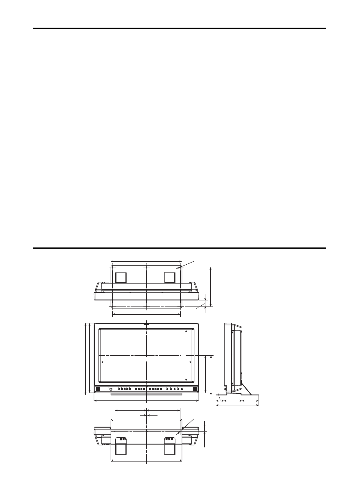
Dimensions
t : mm (inches
456.1 (17-31/32)
441.5 (17-3/8)
450 (17-3/4)
430 (17)
575.8 (22-3/4) (Display area)
6- Ø5
40.5 (1-5/8)
323.7 (12-3/4) (Display area)
250 (9-7/8)
251 (9-7/8)
236.5 (9-3/8)
663 (26-3/32)
213 (8-3/8)199 (7-7/8)
4.5 (1/8)
3-M
4
50.5 (2)
105.5 (4 -1/8)
114 (4-1/2)
270 (10-5/8)
When installing the monitor in one place
permanently, we recommend that you fix
the monitor in place using the screw
holes in the lower part of the stand.
27.7 (1-1/8)
7
Page 8
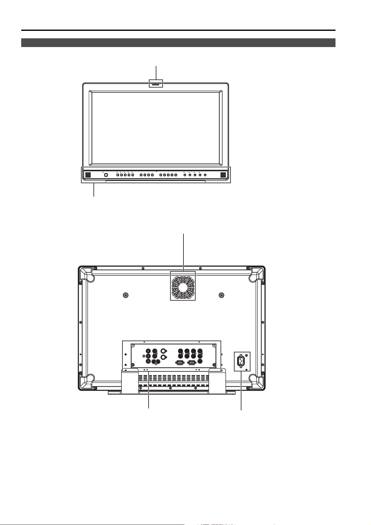
Controls and Their Functions
Video monitor unit
Front view
Rear view
Tally (J page 26, 30)
Front panel (J page 9)
Fan (J page 21)
Rear panel (J page 10) Power supply (J page 11)
8
Page 9
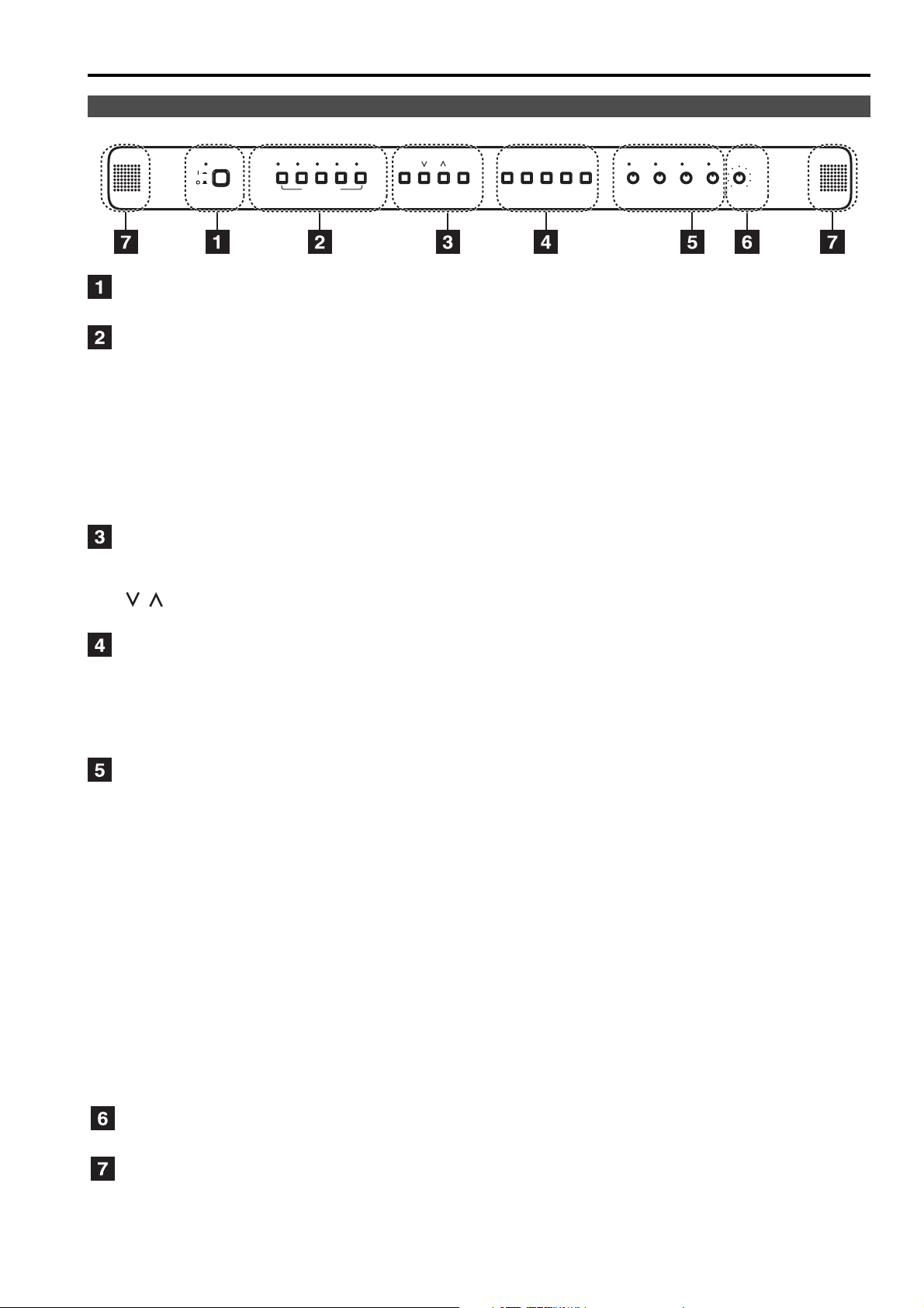
Controls and Their Functions (continued)
Front panel
POWER
VIDEO
Y/C
INPUT SELECT
BPR/
YP
SDI 2
SDI 1
MENU
RGB
ENTER
1
FUNCTION
2
3
4
5
PHASE CHROMA BRIGHT
CONTRAST/
BACKLIGHT
VOLUME
POWER switch
This switches the power supply ON/OFF. When the power is ON, the LED (green) lights up.
INPUT SELECT button
This selects the signal input line. The green LED light above the button indicates the selected input signal.
VIDEO : Video input
Y/C : Y/C input
SDI1 : Serial digital interface input (HD/SD compatible)
SDI2 : Serial digital interface input (HD/SD compatible)
YP
BPR/RGB : Analog component (YPBPR) or RGB input. Also compatible with PC input RGB.
* When using PC Input, select “RGB-COMP.” from “YP
BPR/RGB” in the “INPUT SELECT”
menu (Jpage 27).
* The monitor retains the input signal settings selected from the last time the monitor was swiched ON or OFF.
MENU button
This is used for menu display, selecting settings, and adjustments.
MENU : Push to display or exit the menu, and to return to the previous menu screen.
, : Push to move the cursor up or down, or to select an item.
ENTER : Push to confirm a setting, and to display a submenu.
FUNCTION button
FUNCTION 1 : Carries out the item selected in the menu.
FUNCTION 2 : Carries out the item selected in the menu.
FUNCTION 3 : Carries out the item selected in the menu.
FUNCTION 4 : Carries out the item selected in the menu.
FUNCTION 5 : Carries out the item selected in the menu.
Picture adjusting knob
PHASE 0 – 60 (30)
CHROMA 0 – 60 (30)
BRIGHT 0 – 60 (30)
CONTRAST 0 – 60 (50)/BACKLIGHT 0 – 60 (60)
( ) denotes factory preset values
A rotating knob that can be pushed to operate. When the picture adjusting knob is pressed, its status is
displayed and adjustment becomes possible. The setting values are saved by pushing the knob again.
When values are changed from the factory preset values, the LED above the knob (amber) lights.
The setting values are loaded when the monitor’s power is switched ON. The setting values are saved when
the knob is pushed, or when 10 seconds pass after changing the settings. However, operating changes
cannot be made in the following cases.
* When the control lock is on, the key mark appears and setting values cannot be changed (J page 29).
* Only items selected in the menu can be adjusted with [CONTRAST] and [BACKLIGHT] (J page 21).
* When the MONO function is ON (J page 19), [PHASE] and [CHROMA] operations are disabled.
* When using “RGB-COMP.” input, [PHASE] and [CHROMA] operations are disabled.
* While operating HV DELAY (J page 24) (when set to any other setting than OFF), [BRIGHT] operation is
disabled.
Volume knob
You can adjust the speaker volume by rotating the volume knob.
Speaker
Audio input from the AUDIO input terminal or SDI terminal (embedded audio) can be heard.
Audio output setting is in the menu.
9
Page 10

Controls and Their Functions (continued)
Rear panel
12 3 4
5
6 78
SDI (HD/SD) terminal (BNC)
IN1 : This is the SDI input terminal (compatible with HD/SD automatic switching).
IN2 : This is the SDI input terminal (compatible with HD/SD automatic switching).
SWITCHED OUT
* SDI active through-out
Signal output results only when [SDI1] or [SDI2] is selected in [INPUT SELECT]. No output results when the selected input
is not SDI.
The terminal is compatible with embedded audio.
Outputting signals received through the SDI input terminals and converted to analog is not possible.
When multiple monitors are connected in a daisy chain pattern using the SDI active through-out, flicker or noise may occur
on the screen, depending on the quality of the original signal, lengh of cables or the number of monitors connected.
VIDEO terminal (BNC)
IN : This is the VIDEO signal (composite signal) input terminal.
OUT : This is the composite input signal through-out terminal.
Y/C terminal
IN : This is the Y/C signal (S-video signal) input terminal.
OUT : This is the Y/C input signal through-out terminal.
* Wide display (16:9) information from the input signal is not automatically detected.
Change the aspect ratio settings, referring to SD ASPECT (J page 19) on the VIDEO CONFIG Menu.
YP
BPR/RGB terminal (BNC)
IN : This is the YPBPR/RGB signal input terminal.
OUT : This is the YP
* When using the RGB signal, you can also connect the external synchronizing signal to the SYNC/HD
terminal. When using a PC RGB signal, connect the horizontal synchronizing signal to the SYNC/HD
terminal, and the vertical synchronizing signal to the VD terminal.
: This is the active through-out terminal for the SDI input signal being displayed on the screen.
*1*2
*1*2
*1*2
BPR/RGB input signal through-out terminal.
VD IN input terminal
This is the vertical synchronizing signal (VD) input terminal used when connecting to a PC RGB signal.
AUDIO input terminal (Pin terminal)
This is the common audio input terminal for all video input terminals.
* When an embedded audio unit BT-YAE1700G (optional) is attached, SDI input audio is automatically
selected by selecting [SDI1] or [SDI2] with [INPUT SELECT].
GPI input terminal (D-SUB 9-pin)
External control is possible by using a GPI signal.
RS-232C input terminal (D-SUB 9-pin)
External control is possible by using a RS-232C signal.
*1 When a cable is not connected to the through-out terminal, the VIDEO IN terminal automatically bears 75 Ω
resistance. When the cable is connected, 75 Ω resistance is removed.
*2 When the through-out terminal is used, depending on connected equipment, the unit's picture level may be
exceeded because 75 Ω resistance at the end of the terminal is automatically removed.
10
Page 11
Power Supply
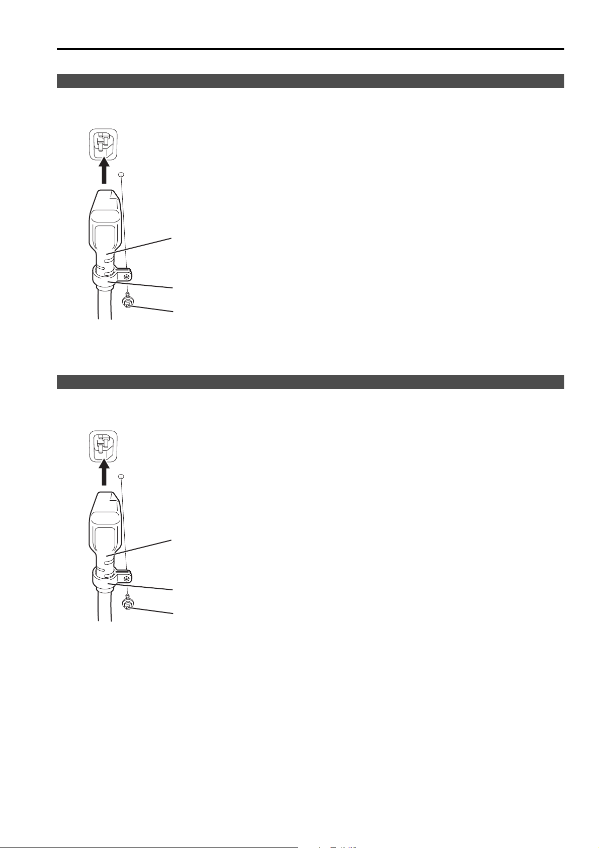
Connecting and fixing the power cord (for the U.S.A. and Canada)
1. Attach the power cord to the monitor unit. 2. Connect the power cord to the power outlet.
Using the power cord
hook and the screw,
attach the power cord to
the monitor unit.
Power cord
Power cord hook
Screw
Connecting and fixing the AC mains lead (for others)
1. Attach the mains lead to the monitor unit. 2. Connect the AC mains lead to the power outlet.
Using the AC mains lead
hook and the screw,
attach the AC mains lead
to the monitor unit.
AC mains lead
AC mains lead hook
Screw
11
Page 12
How to Use the On Screen Menu
Six types of information are displayed on the screen. The input signal status, picture adjusting knob status,
sharpness display, function display, audio level meter display and the menu display.
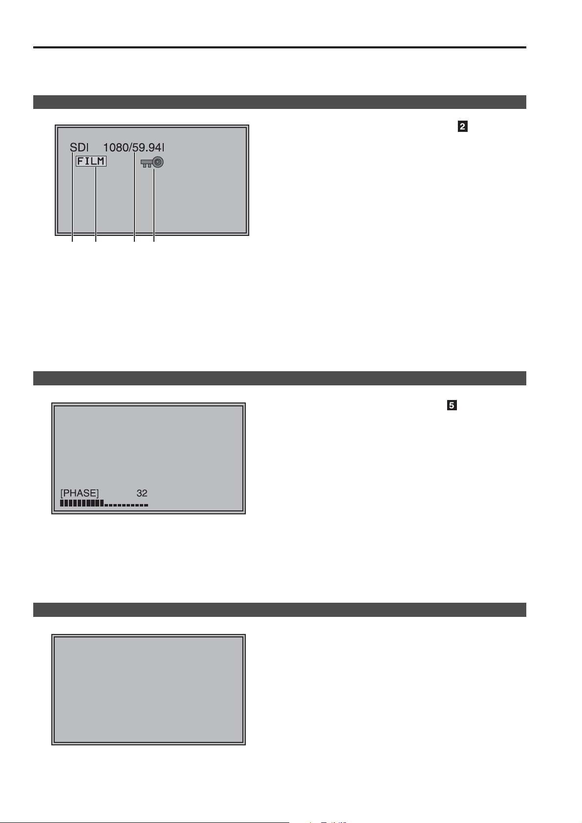
Input signal status
1. The selected input line (J page 9, )
• VIDEO, Y/C, SDI1, SDI2,
SDI1
412 3
YP
BPR/RGB-VIDEO/RGB-COMP.
2. Various display (FILM mode)
• Displayed when “FILM” is selected in “GAMMA
SELECT”.
3. Signal format
• The display status can be set in “STATUS
DISPLAY” in the “SYSTEM CONFIG” menu
(J page 21).
• If “UNSUPPORT SIGNAL” is displayed, then either
the current input signal is not supported or the
“INPUT SELECT” menu setting needs to be
changed.
• When “NO SIGNAL” is displayed, there is no input
signal.
4. Various display (lock setting)
• Displayed when control lock is ON.
Note:
“UNSUPPORT SIGNAL” and “NO SIGNAL” may not be
displayed correctly.
Picture adjusting knob status
Sharpness display
Picture adjusting knob (J page 9, )
• This knob can be rotated and pushed.
• The status display appears when the knob is
pushed.
The display disappears when the knob is pushed
again, or if the knob is not operated for 10 seconds.
• Settings can only be adjusted in the status display.
• The display position can be changed (J page 21
“ROTARY POSITION”).
Status display:
PHASE, CHROMA, BRIGHT, CONTRAST or BACKLIGHT
Note:
The volume knob status display is not displayed on the
screen.
• Sharpness is displayed when it is set.
• The display disappears if remains idle for 2 minutes.
12
SHARPNESS
30
Page 13

How to Use the On Screen Menu (continued)
Function display
• You can set FUNCTION display in the menu.
• When “FUNCTION DISPLAY” (J page 22) is “ON”
and either [FUNCTION1] or [FUNCTION5] is
F1:MARKER
F2:WFM
F3:LEVEL METER
F4:PIXEL TO PIXEL
F5:PIXEL POS.
XXXXX
Audio level meter display
11
33
55
77
22
44
66
88
pressed, the unit displays the status of the
FUNCTION item set.
• The display disappears if remains idle for 2 seconds.
• The operational status is displayed in “XXXXX” (J
page 23 “Operation items displayed when a
FUNCTION button is used”).
• When the signal is SDI, the audio level is displayed
on the white skeleton bar meter.
• You can switch the level display on and off, and set
the number of displayed channels using the menu.
• The 0 dB line and channel display can be switched
on and off from the menu.
Channel
display
Level
display
0 dB
line
Menu display
[MAIN MENU]
FUNCTION
HOURMETER
MENU
Displays the operation explanation for the
menu button.
• This is displayed when the menu is used.
• The display disappears if remains idle for 2 minutes.
• The display position can be changed (J page 21
“MENU POSITION”).
13
Page 14

How to Use the On Screen Menu (continued)
Menu operations
1. Push [MENU] to display the MAIN menu.
2. Push [ , ] to select the menu, then push
[ENTER].
[MAIN MENU]
FUNCTION
HOURMETER
MENU
3. Push [ , ] to select the sub menu, then push
[ENTER].
The setting values in the sub menu change to green.
MARKER
MARKER
16:9
4:3
BACK
CENTER
GPI PRESET1
GPI PRESET2
4. Push [ , ] to select the setting values, then
push [ENTER].
Push [MENU] to cancel.
MARKER
MARKER
16:9
4:3
BACK
MARKER
GPI PRESET1
GPI PRESET2
OFF
OFF
OFF
NORMAL
OFF
4:3
4:3
SET
ON
OFF
OFF
NORMAL
OFF
4:3
4:3
SET
To return to the previous screen
Push [MENU].
14
Page 15

User Data
You can change the menu setting values and picture adjusting knob settings, then save and load up to 5
combinations of screen adjustment values as user data. You can also return the setting values and adjustment
values to the factory preset settings.
The following settings are included in user data.
• Menu settings except for “SETUP LOAD/SAVE” (including the button function settings on the front of the monitor)
• Screen adjustment values changed in picture adjusting knob
Saving user data
1. Push [MENU] to display the MAIN menu.
2. Push [ , ] to select the “SYSTEM CONFIG”
menu and push [ENTER].
3. Push [ , ] to select the “SETUP SAVE” sub
menu and push [ENTER].
The setting values in the sub menu change to green.
CONT./BACK.
BACKLIGHT
SUB WINDOW
WFM POSITION
MENU POSITION
ROTARY POSITION
STATUS DISPLAY
SETUP LOAD
SETUP SAVE
FAN MOTOR
COLOR SPACE
BACKLIGHT
60
FULL
RB
CENTER
LB
3SEC OFF
FACTORY
USER1
OFF
EBU
Loading user data
1. Push [MENU] to display the MAIN menu.
2. Push [ , ] to select the “SYSTEM CONFIG”
menu and push [ENTER].
3. Push [ , ] to select the “SETUP LOAD” sub
menu and push [ENTER].
The setting values in the sub menu change to green.
CONT./BACK.
BACKLIGHT
SUB WINDOW
WFM POSITION
MENU POSITION
ROTARY POSITION
STATUS DISPLAY
SETUP LOAD
SETUP SAVE
FAN MOTOR
COLOR SPACE
BACKLIGHT
60
FULL
RB
CENTER
LB
3SEC OFF
FACTORY
USER1
OFF
EBU
Changes to green
4. Push [ , ] to select the file you wish to save
to from “USER1” – “USER5”, then push [ENTER].
The following screen appears.
SETUP SAVE
5. Select “YES”, and push [ENTER].
The user data is saved.
To return to the previous screen
Push [MENU].
Changes to green
4. Push [ , ] to select the file you wish to load to
from “USER1” – “USER5”, then push [ENTER].
The following screen appears.
To return to the factory preset setting values, select
“FACTORY”.
SETUP LOAD
5. Select “YES”, and push [ENTER].
The user data is loaded.
15
Page 16

Main Menu
Menu configuration
MAIN MENU
MARKER
VIDEO CONFIG
SYSTEM CONFIG
FUNCTION
GPI
INPUT SELECT
AUDIO
CONTROL
HOURMETER
CONT./BACK.
BACKLIGHT
SUB WINDOW
WFM POSITION
MENU POSITION
ROTARY POSITION
STATUS DISPLAY
SETUP LOAD
SETUP SAVE
FAN MOTOR
COLOR SPACE
FUNCTION1
FUNCTION2
FUNCTION3
FUNCTION4
FUNCTION5
FUNCTION DISPLAY
VIDEO/ Y/C
NTSC SETUP
BPR/RGB
YP
COMPONENT LEVEL
RGB SYNC
COMP.
INPUT SELECT
EMBEDDED SELECT L
EMBEDDED SELECT R
LEVEL METER
0 dB POINT
CH
CONTROL
LOCAL ENA.
OPERATION
LCD
FAN
GAMMA SELECT
FILM GAMMA
COLOR TEMP.
SHARPNESS MODE
SHARPNESS H
SHARPNESS V
I-P MODE
MONO
ANAMO
SD ASPECT
SCAN
NOISE WIPE
AUTOSETUP
H POSITION
V POSITION
PHASE
CLOCK
WXGA/XGA
*[WHITE BALANCE VAR1-3]
USER0-63
D93
D65
D56
VAR1
VAR2
VAR3
GPI CONTROL
GPI1
GPI2
GPI3
GPI4
GPI5
GPI6
GPI7
GPI8
MARKER
16:9
4:3
BACK
CENTER
GPI PRESET1
GPI PRESET2
COLOR TEMP.
GAIN RED
GAIN GREEN
GAIN BLUE
BIAS RED
BIAS GREEN
BIAS BLUE
RESET
16
Page 17

Main Menu (continued)
MARKER
The underlined values are factory preset setting values.
Sub menu Settings Explanation
MARKER
<OFF>
<ON >
16:9
*2*3
<OFF>
<4:3 >
<13:9>
<14:9>
<CNSCO>
<VISTA>
<95%>
<93%>
<90%>
<88%>
<80%>
4:3
*2*4
<OFF>
<95%>
<93%>
<90%>
<88%>
<80%>
BACK
*2
<
<HALF>
<BLACK>
CENTER
*2
<OFF>
<ON>
GPI PRESET1
*5
<4:3>
<13:9>
<14:9>
<CNSCO>
<VISTA>
GPI PRESET2
*5
<95% (16:9)>
<93% (16:9)>
<90% (16:9)>
<88% (16:9)>
<80% (16:9)>
<95% (4:3)>
<93% (4:3)>
<90% (4:3)>
<88% (4:3)>
<80% (4:3)>
*1 The setting becomes “On” when the unit receives marker-related control during REMOTE operation. (Priority
goes to GPI when GPI settings exist.)
*2 When controlling the marker settings using the GPI function (J page 30), these settings become disabled.
These are not operated when the 2 screens are displayed.
*3 These are only enabled when the HD signal and SD signal aspect ratio settings are 16:9.
*4 These are only enabled when the SD signal aspect ratio setting is 4:3.
*5 When setting “GPI PRESET1” or “GPI PRESET2” using GPI function, the REMOTE function depending RC-
232C becomes disabled (error response: ER001).
*1
NORMAL
Used to make MARKER settings effective.
Used to select/display the type of marker when the aspect ratio
setting is 16:9.
<OFF> Marker not displayed.
<4:3> 4:3 marker
<14:9> 14:9 marker
<VISTA> VISTA marker
<93%> 93%
<88%> 88%
Area marker
Area marker
<13:9> 13:9 marker
<
CNSCO
> CNSCO marker
<95%> 95%
<90%> 90%
<80%> 80%
Area marker
Area marker
Area marker
Used to select/display the type of marker when the aspect ratio
setting is 4:3.
<OFF> Marker not displayed.
<95%> 95%
<90%> 90%
<80%> 80%
>
Used to select the background brightness excluding the marker.
<
NORMAL
Area marker
Area marker
Area marker
> Normal background
<93%> 93%
<88%> 88%
Area marker
Area marker
<HALF> Background brightness 50%
<BLACK> Background brightness 0% (Black)
Used to display the center marker.
<OFF> Not displayed
<ON> Displayed
GPI PRESET1: Used to select the marker to be displayed using the
GPI terminal “MARKER1 ON/OFF” operation (J page 30).
GPI PRESET2: Used to select the marker to be displayed using the
GPI terminal “MARKER2 ON/OFF” operation (J page 30).
<4:3> 4:3 marker
<13:9> 13:9 marker
<14:9> 14:9 marker
<
CNSCO
>CNSCO marker
<VISTA> VISTA marker
<95% (16:9)> 95% Area marker when the aspect ratio is 16:9.
<93% (16:9)> 93% Area marker when the aspect ratio is 16:9.
<90% (16:9)> 90% Area marker when the aspect ratio is 16:9.
<88% (16:9)> 88% Area marker when the aspect ratio is 16:9.
<80% (16:9)> 80% Area marker when the aspect ratio is 16:9.
<95% (4:3)> 95% Area marker when the aspect ratio is 4:3.
<93% (4:3)> 93% Area marker when the aspect ratio is 4:3.
<90% (4:3)> 90% Area marker when the aspect ratio is 4:3.
<88% (4:3)> 88% Area marker when the aspect ratio is 4:3.
<80% (4:3)> 80% Area marker when the aspect ratio is 4:3.
17
Page 18

Main Menu (continued)
Types of MARKER
g 16:9 marker
(Displayed when using HD, or when using SD
with a 16:9 aspect ratio)
The marker is only displayed as a vertical bar. In
addition, the section becomes the “MARKER
BACK” item.
4:3 marker 13:9 marker
14:9 marker
VISTA marker, CNSCO marker
A horizontal dotted line is displayed as the marker.
g
4:3 marker
(Displayed when using SD with a 4:3 aspect ratio)
A dotted line is displayed as the marker.
95% Area marker 93% Area marker
90% Area marker 88% Area marker
80% Area marker
(Displayed when using HD, or when using SD with a 16:9 aspect ratio)
A dotted line is displayed as the marker.
VISTA marker CNSCO marker
When “UNDER” is set in “SCAN” in the “VIDEO
CONFIG” menu, a vertical dotted line is also
displayed as the marker.
VISTA marker CNSCO marker
Area marker
A dotted line is displayed as the marker.
95% Area marker 93% Area marker
90% Area marker 88% Area marker
95% Area marker 93% Area marker
90% Area marker 88% Area marker
80% Area marker
*
You can display 4:3 marker at the same time as 16:9 marker.
Simultaneously display example
The section becomes the “MARKER BACK” item. The
background selected with the 16:9 marker is controlled.
16:9 marker:
80% Area marker
95% Area marker
95% Area marker
4:3 marker:
80% Area marker
80% Area marker
18
g Center marker
Center marker
The marker is displayed in
the center of the picture.
Page 19

Main Menu (continued)
VIDEO CONFIG
The underlined values are factory preset setting values.
Sub menu Settings Explanation
GAMMA
SELECT
*1*2
<STANDARD>
<FILM>
<STDIO/PST>
*2
FILM GAMMA
<VARICAM>
<OTHER>
COLOR TEMP.
<USER0–63>
<D93>
<D65>
<D56>
<VAR1>
<VAR2>
<VAR3>
SHARPNESS
*2
MODE
SHARPNESS H
SHARPNESS V
I-P MODE
*2*6
*2
*2
<HIGH>
<LOW>
<0–30>
<0–30>
<MODE2>
*3
*3
*3
<MODE1>
MONO
*2
<OFF>
<ON>
ANAMO
*2*7
<OFF>
<ON>
SD ASPECT
*2
<4:3>
<16:9>
SCAN
*2
<NORMAL>
<UNDER>
NOISE WIPE
*2
<OFF>
<ON>
*1 During 2 screen display, the changes are not reflected in the still image of the main window.
*2 When “RGB-COMP.” is selected in “YP
*3 The following sharpness values can each be set,
1) VIDEO system input line (VIDEO,Y/C)(Factory settings are SHARPNESS MODE : LOW, SHARPNESS H/V : 0)
2) any other input line’s HD (Factory settings are SHARPNESS MODE : HIGH, SHARPNESS H/V : 0)
3) any other input line’s SD (Factory settings are SHARPNESS MODE : LOW, SHARPNESS H/V : 0)
and the setting values for the selected input signal from within this group is displayed. The adjustment status is
displayed in the bottom right when selected.
*4 When “VAR1”, “VAR2” or “VAR3” is selected, the monitor switches to WB adjustment mode (
*5 When selecting USER0–63
1) Push [ENTER] (USER changes to blue). 2) Select 0–63 with [ , ], and push [ENTER].
*6 When using
“SUB WINDOW” function (J page 24),
1) change the setting after releasing
2) we recommand
“MODE2” for the image with a fast movement.
*7 During Anamo size display, “SCAN” change is not reflected.
Used to select the gamma curve.
<STANDARD>Standard mode <FILM>FILM mode
<STDIO/PST>Color emphasis mode (in the gamma characteristic in
which shades are valued more than the contrasts, it is suitable for
use by the studio and the post production, etc. )
When FILM is selected, mark is displayed in the top left of the screen.
Used to select the type of FILM gamma mode.
<VARICAM> VARICAM use
<OTHER> When using other types than VARICAM
*5
Used to select the color temperature.
<USER0–63> Adjustable settings 0–63 (color temperature around 3000K–9300K)
<D93> Color temperature around 9300K
<D65> Color temperature around 6500K
<D56> Color temperature around 5600K
<VAR1> WB adjustment mode
<VAR3> WB adjustment mode
*4
<VAR2> WB adjustment mode
*4
Used to select the width of the sharpness edge.
<HIGH> Thin edge <LOW> Thick edge
Used to set the sharpness in the horizontal direction.
When adjusting, the item display moves to the lower part of the screen.
Used to set the sharpness in the vertical direction.
When adjusting, the item display moves to the lower part of the screen.
Used to select IP conversion mode. (J page 20 : About IP Mode)
<MODE2> Field Interpolation <MODE1> Frame Interpolation
Used to switch between color and monochrome (MONO).
<OFF> Color <ON> Monochrome
* When this is ON, the picture adjusting knob [CHROMA] setting is fixed at 0.
If an Anamo lens has been used on the camera, and input through
SDI 720/60P, 59.94P, the picture is resized to Anamo size
magnification. (a vertically compressed signal can be amplified
vertically and corrected when it is displayed.)
Used for setting the aspect ratio settings when using SD signal input.
<4:3> 4:3 display <16:9> 16:9 display
Used to set under-scan and normal display.
<NORMAL>Normal display <UNDER>Under-scan
<OFF> This makes a fluid and smooth contrast obtainable.
This is especially effective for continuously changing the contrast of
the source signal or CG signal when the S/N is very high.
<ON> Noise reduction mode. Depending on the camera, this mode can
be especially effective for dark scenes. We recommend leaving
this setting “ON” under normal conditions.
BPR
/RGB” in the “INPUT SELECT” menu (J page 27), this does not operate.
J
page 20).
“SUB WINDOW” function
.
*4
19
Page 20

Main Menu (continued)
3
About IP Mode
By selecting “MODE1”, you can convert IP through Frame Interpolation.
This unit has reduced the Frame Interpolation delay to 1 field or less, compared to our old models having caused
1 frame delay or more.
Factory preset setting value is “MODE1” recommended for normal use. Depending on images, in very rare
cases, noise may occur on the screen. In such a case, “MODE 2” is recommended.
By selecting “MODE2”, you can convert IP through Field Interpolation.
Depending on still images, etc., flickers may occur on the screen. In such a case, “MODE 1” is recommended.
g WB adjustment mode
You can adjust “WHITE BALANCE VAR1” – “WHITE BALANCE VAR3” (WB) by selecting “VAR1” – “VAR3” in
“COLOR TEMP.” in the “VIDEO CONFIG” menu.
The underlined values are factory preset setting values.
Sub menu Settings Explanation
*1
COLOR TEMP.
<USER0–63>
<D93>
<D65>
<D56>
GAIN RED
GAIN GREEN
GAIN BLUE
<0–511>
(Factory presets are values
for color temperature <D65>.)
* The presets are values
adjusted before shipment
from factories.
BIAS RED
BIAS GREEN
<-512–511>
(Factory preset settings: 0)
BIAS BLUE
RESET
*1 When “COLOR TEMP.” is selected and [ENTER] is pressed following item change, the display changes to the
confirmation screen. Selecting “YES” and pressing [ENTER] on this screen return GAIN and BIAS values to the
selected color temperature values.
*2 When adjusting, the item display moves to the lower part of the screen.
Used to select the color temperature that will become the
basis for adjustments.
<USER0–63>
Adjustable settings 0–63 (color
temperature around 3000K–9300K)
<D93> Color temperature around 9300K
<D65> Color temperature around 6500K
<D56> Color temperature around 5600K
GAIN elements for RED are adjusted.
GAIN elements for GREEN are adjusted.
GAIN elements for BLUE are adjusted.
BIAS elements for RED are adjusted.
BIAS elements for GREEN are adjusted.
BIAS elements for BLUE are adjusted.
*2
*2
*2
*2
*2
*2
“GAIN RED” – “BIAS BLUE” values are reset to color
temperatures values selected in “COLOR TEMP.”.
20
Page 21

Main Menu (continued)
SYSTEM CONFIG
The underlined values are factory preset setting values.
Sub menu Settings Explanation
CONT./BACK.
BACKLIGHT
SUB WINDOW
WFM POSITION
MENU
POSITION
ROTARY
POSITION
STATUS DISPLAY
SETUP LOAD
SETUP SAVE
FAN MOTOR
COLOR SPACE
*1 When the monitor is shipped from the factory, “USER1” – “USER5” and “FACTORY” all have the same details.
*2 You cannot save or load the settings for “H POSITION”, “V POSITION”, “PHASE” and “CLOCK” (J page 27).
*3 Factory preset settings are The U.S.A. and Canada: SMPTE-C, Others: EBU.
<CONTRAST>
<BACKLIGHT>
Used to select the function to be assigned to [CONTRAST/
BACKLIGHT] (a knob on the front panel).
<CONTRAST>
Used to adjust CONTRAST.
<BACKLIGHT>
Used to adjust BACKLIGHT.
< 0-60
> Used to adjust the LCD backlight level.
<FULL>
<PART>
Used to select the type of sub window.
<FULL>
Used to reduce the whole input signal screen, and arrange it
horizontally when it is displayed.
<PART>
Used to cut out the central section of the input signal screen, and
arrange it horizontally when it is displayed (Displayed at the same size
as the previous screen).
<LB>
<RB>
<RT>
Used to set the WFM display position.
<LB> Bottom left of the screen <RB> Bottom right of the screen
<RT> Top right of the screen <LT> Top left of the screen
<LT>
<CENTER>
<LB>
<RB>
<RT>
Used to set the on screen menu display position.
<CENTER> Center of the screen
<LB> Bottom left of the screen <RB> Bottom right of the screen
<RT> Top right of the screen <LT> Top left of the screen
<LT>
<CENTER>
<LB>
<RB>
<RT>
<LT>
<CONTINUE>
<3SEC OFF>
<OFF>
Used to set the picture adjusting knob status (on screen menu) display
position.
<CENTER> Center of the screen
<LB> Bottom left of the screen <RB> Bottom right of the screen
<RT> Top right of the screen <LT> Top left of the screen
Used to set the input signal status (on screen menu) display status.
<CONTINUE> Displayed normally.
<3SEC OFF> After changing status, it is displayed for approximately
3 seconds, and then disappears.
<OFF> Not displayed.
<FACTORY>
<USER1>
<USER2>
<USER3>
<USER4>
<USER5>
<USER1>
<USER2>
<USER3>
<USER4>
<USER5>
*1*2
*1*2
*1*2
*1*2
*1*2
*2
*2
*2
*2
*2
<OFF>
<ON>
The saved factory preset setting values (FACTORY) or the user data
(USER 1–USER 5) are loaded. Also after loading user data, the screen
displays the signal selected before loading data.
Up to 5 sets of user data can be saved (J page 15).
The menu settings and picture adjusting knob adjustment values
(PHASE /CHROMA /BRIGHT /CONTRAST) excluding “SETUP SAVE/
SETUP LOAD” are saved.
Used to set fan operation.
<OFF> The fan is stopped. The brightness of the backlight
automatically lowers.
<ON> The fan operates. The backlight brightness returns to normal.
<EBU>
*3
<SMPTE-C>
Used to set studio-specified colors.
*3
21
Page 22

Main Menu (continued)
FUNCTION
The underlined values are factory preset setting values.
Sub menu Settings Explanation
FUNCTION 1 –
FUNCTION 5
FUNCTION DISPLAY
*1 If these settings are changed, the menu settings will also change.
<HV DELAY>
<AUTOSETUP>
<BLUE ONLY>
<GAMMA SELECT>
<SD ASPECT>
<SCAN>
<SUB WINDOW>
<WFM>
<MARKER>
<PIXEL TO PIXEL>
<PIXEL POS.>
<LEVEL METER>
<MONO>
<UNDEF>
(Factory preset
settings
FUNCTION1:
MARKER
FUNCTION2:
WFM
FUNCTION3:
LEVEL METER
FUNCTION4:
PIXEL TO PIXEL
FUNCTION5:
PIXEL POS.)
<ON>
<OFF>
Used to select the functions to be assigned to individual
buttons [FUNCTION1] to [FUNCTION5] (front-panel buttons).
<HV DELAY>
Displays the synchronizing signal (horizontal, vertical).
The display is switched in the following order.
DELAY OFF J V DELAY J H DELAY J HV DELAY J
DELAY OFF
<AUTOSETUP>
Used to automatically adjust the PC display.
<BLUE ONLY>
Used to cut the red and green signals. You can check the hue
(PHASE) and depth of color (CHROMA). This is switched
between ON/OFF by pushing the button.
<GAMMA SELECT>
Used to display the gamma curve.
The display changes in the following order.
GAMMA STANDARD J GAMMA FILM J
GAMMA STDIO/PST J GAMMA STANDARD
<SD ASPECT>
Used to switch between “16:9” and “4:3”.
<SCAN>
You can switch between “UNDER SCAN” and “NORMAL
SCAN”.
<SUB WINDOW>
You can perform the settings for 2 screen display mode.
The display changes in the following order.
<WFM>
Used to display the wave form monitor.
<MARKER>
Used to switch the marker on and off.
<PIXEL TO PIXEL>
Used to switch the display between the input size and display
size.
<PIXEL POS.>
Used to set the signal display position when PIXEL TO PIXEL
is on.
<LEVEL METER>
Used to switch the AUDIOMETER display.
The display changes in the following order.
<MONO>
Used to switch the display between color and black-andwhite.
<UNDEF>
No settings
Used to make display settings for the functions assigned to
individual buttons [FUNCTION1] to [FUNCTION5] (frontpanel buttons).
<ON>
The selected function is displayed.
<OFF>
The selected function is not displayed.
*1
SINGLE J FULL/PARTJ STILLJ SINGLE
METER 8CH J METER 4CH J METER 2CH J OFFJ
METER 8CH
*1
*1
22
Page 23

Main Menu (continued)
g Restrictions on various FUNCTION settings
Under the following conditions, various settings are disabled.
Setting Disabling condition
HV DELAY
AUTO
SETUP
GAMMA
SELECT
SD ASPECT
SCAN
SUB
WINDOW
WFM
MARKER
PIXEL TO
PIXEL
PIXEL POS.
MONO
In SUB WINDOW, WFM or PIXEL TO PIXEL mode, “INVALID FUNCTION” is displayed and the
setting is disabled.
When “YP
BPR/RGB” set in “INPUT SELECT” menu is “RGB-COMP.”, “INVALID FUNCTION” is
displayed and the setting is disabled.
When “YP
BPR/RGB” set in “INPUT SELECT” menu is other than “RGB-COMP.”, “NOT RGB-
COMP. CH” is displayed and the setting is disabled.
When “YP
BPR/RGB” set in “INPUT SELECT” menu is “RGB-COMP.” and there is NO SIGNAL,
“INCOMPLETE” is displayed and the setting is disabled.
When GPI item is set, “INVALID FUNCTION” is displayed and the setting is disabled.
When “YP
BPR/RGB” set in “INPUT SELECT” menu is “RGB-COMP.”, “INVALID FUNCTION” is
displayed and the setting is disabled.
When GPI item is set, “INVALID FUNCTION” is displayed and the setting is disabled.
When SUB WINDOW (still picture) or HD display (including PIXEL TO PIXEL) is on, “INVALID
FUNCTION” is displayed and the setting is disabled.
When GPI item is set, “INVALID FUNCTION” is displayed and the setting is disabled.
In SUB WINDOW or PIXEL TO PIXEL mode, “INVALID FUNCTION” is displayed and the setting
is disabled.
When “YP
BPR/RGB” set in “INPUT SELECT“ menu is other than “RGB-COMP.”, “INVALID
FUNCTION” is displayed and the setting is disabled.
When “RGB-COMP.” is selected in SUB WINDOW with a motion picture on, the screen turns SINGLE.
When an item other than “RGB-COMP.” is selected, two motion pictures are displayed on the
screen. When a still picture is on, blackout occurs.
In SUB WINDOW or PIXEL TO PIXEL mode, “INVALID FUNCTION” is displayed and the setting
is disabled.
When “YP
BPR/RGB” set in “INPUT SELECT” menu is “RGB-COMP.” or “RGB-VIDEO”, “INVALID
FUNCTION” is displayed and the setting is disabled.
When “YP
BPR/RGB” set in “INPUT SELECT” menu is “RGB-COMP.”, “INVALID FUNCTION” is
displayed and the setting is disabled.
When GPI item is set or in SUB WINDOW mode, “INVALID FUNCTION” is displayed and the
setting is disabled.
When “YP
BPR/RGB” set in “INPUT SELECT” menu is “RGB-COMP.” or “RGB-VIDEO”, “INVALID
FUNCTION” is displayed and the setting is disabled.
In SUB WINDOW mode, “INVALID FUNCTION” is displayed and the setting is disabled.
When PIXEL TO PIXEL is OFF, “PIXEL TO PIXEL OFF” is displayed and the setting is disabled.
When PIXEL TO PIXEL is 720P display, the position becomes CENTER.
When the display position is not CENTER in PIXEL TO PIXEL mode during 1080P display and
the 720P signal is selected, the display position moves to CENTER.
When GPI item is set, “INVALID FUNCTION” is displayed and the setting is disabled.
g Operation items displayed when a FUNCTION button is used
When any of the buttons, [FUNCTION1] to [FUNCTION5], is pressed, the following messages are displayed
according to the operation assigned to the pressed button.
•HV DELAY
DELAY OFF, V DELAY, H DELAY, HV DELAY
• AUTOSETUP
COMPLETE: Display for completion
INCOMPLETE: Display for incompletion
NOT RGB-COMP. CH
• GAMMA SELECT
GAMMA STANDARD, GAMMA FILM,
GAMMA STDIO/PST
• SCAN
NORMAL SCAN, UNDER SCAN
• SUB WINDOW
• MARKER
MAKER OFF, 4:3 MARKER, 13:9 MARKER,
14:9 MARKER, VISTA MARKER,
CNSCO MARKER, 95% MARKER, 93% MARKER,
90% MARKER, 88% MARKER, 80% MARKER
• PIXEL TO PIXEL/PIXEL POSITION
CENTER, LEFT TOP, LEFT BOTTOM,
RIGHT TOP, RIGHT BOTTOM
PIXEL TO PIXEL OFF
• LEVEL METER
METER OFF, METER 2CH, METER 4CH,
METER 8CH
SINGLE, FULL/PART, STILL
23
Page 24

P
P
P
P
Main Menu (continued)
g About HV DELAY
This displays the video blanking period. By pushing the button, you can switch through the H blanking display J
V blanking display J H and V blanking display J no blanking display.
g About the SUB WINDOW
You can compare saved still and moving images by using the “SUB WINDOW” function to separate the main
window into 2 displays as shown below.
Depending on the settings of the “SUB WINDOW” (FULL, PART) in the “SYSTEM CONFIG” menu (J page 21) it
can be switched as shown below.
The display changes each time you press one of the buttons, [FUNCTION1] to [FUNCTION5] (J page 22),
assigned with the [SUB WINDOW] function. (To use the “SUB WINDOW” function, you must assign it to one of
the [FUNCTION1] to [FUNCTION5] buttons.)
When setting “I-P MODE” function (J page 19),
1)change the setting after releasing “SUB WINDOW” function.
2)we recommand “MODE2” for the image with a fast movement.
•FULL
The main window is reduced and made into 2 sub window (sub window+sub window).
Press the FUNCTION button assigned with the SUB WINDOW function.
Normal window
(main window)
ress the
same button
again.
moving image
Before inputting the image
(sub window+sub window)
moving image moving image
After inputting the image
(sub window+sub window)
ress the
same button
again.
still image moving image
•PART
Only the sub window size is cut out of the main window, and the cut section is made into 2 sub window images
(sub window+sub window).
Press the FUNCTION button assigned with the SUB WINDOW function.
Normal window
(main window)
ress the
same button
again.
moving image
Before inputting the image
(sub window+sub window)
moving image moving image
After inputting the image
(sub window+sub window)
ress the
same button
again.
still image moving image
The central section is cut out Lines up and displays the
section cut out of the main
window
The window is displayed in 16:9 aspect.
Precautions when selecting FULL/PART
This function compares screens with the same input terminal and same format. If different input formats, or if
signals are input between different input channels, the sub-window (left side, still image) becomes blurred and
blanking occurs. However, if the same format signals are input into the input terminal when acquiring the still image,
the images will be displayed correctly.
24
Page 25

P
Main Menu (continued)
g About WFM
You can display the wave form monitor using the “WFM” function.
The display changes each time you press one of the buttons, [FUNCTION1] to [FUNCTION5] (J page 22),
assigned with the [WFM] function (To use the “WFM” function, you must assign it to one of the [FUNCTION1] to
[FUNCTION5] buttons).
Press the FUNCTION button assigned
with the WFM function once.
Normal window WFM display
ress the
same button
again.
WFM (Wave Form Monitor)
The window is displayed in 16:9 aspect.
Restrictions on WFM
Even if “WFM” has turned ON”, “WFM” is not displayed when using the “PIXEL TO PIXEL” function, “YP
BPR/RGB”
set in “INPUT SELECT” menu is “RGB-COMP.” or “RGB-VIDEO”, or using the “SUB WINDOW” function.
g About PIXEL TO PIXEL and PIXEL POS.
Using the “PIXEL TO PIXEL” function, you can confirm a picture with the actual pixel count (only when the input
is an HD signal).
First, press one of the buttons, [FUNCTION1] to [FUNCTION5] (J page 22), assigned with the “PIXEL TO
PIXEL” function to turn it “ON”. With the function on, press another one of the buttons, [FUNCTION1] to
[FUNCTION5] (J page 22), assigned with “PIXEL POS.”. Each time the button assigned with “PIXEL POS.” is
pressed, the signal display position switches. (To use the “PIXEL TO PIXEL” function, “PIXEL TO PIXEL” and
“PIXEL POS.” must be assigned to any two of the buttons, [FUNCTION1] to [FUNCTION5].)
The underlined values are factory preset setting values.
Sub menu Settings Explanation
PIXEL TO PIXEL
PIXEL POS.
*1*2
<OFF>
<ON>
<CENTER>
<LEFT TOP>
<RIGHT TOP>
<RIGHT
BOTTOM>
<LEFT
BOTTOM>
Used to set the input signal size as the display size.
Compatible formats
1080/60I/59I/50I/30P/29P/25P/24P/23P/24P
720/60P/59P/50P(SDI/YP
Used to set the signal display position when PIXEL TO PIXEL
*3
is on.
BPR)
SF/23PSF,
<CENTER> center
<LT> top left
<RT> top right
<RB> bottom right
<LB> bottom left
*1 When PIXEL TO PIXEL is on, the following menu settings become invalid:
“ON” for “ANAMO” and “UNDER” for “SCAN” set in “VIDEO CONFIG”
Various “HV DELAY” settings in “FUNCTION”
“MARKER display”
*2 When the input signal is “SDI1”, “SDI2” or “YP
BPR”, the setting takes effect. However, 1080/60P and 1080/50P
signals are excluded.
*3 When the input signal format is 720, only CENTER is displayed.
25
Page 26

Main Menu (continued)
GPI
The “GPI CONTROL” item is used to set enable/disenable of all GPI functions, and assigns functions to each of the
GPI terminal pins (J page 30).
The underlined values are factory preset setting values.
Sub menu Settings Explanation
GPI CONTROL
GPI1–GPI8
<DISENABLE>
<ENABLE>
<UNDEF>
<MARKER1 ON/OFF>
<MARKER2 ON/OFF>
<MARKER BACKHALF>
<MARKER BACKBLACK >
<CENTER MARKER>
<INPUT SEL. VIDEO>
<INPUT SEL. Y/C>
<INPUT SEL. SDI1>
<INPUT SEL. SDI2>
<INPUT SEL. YP
<SD ASPECT>
<SCAN>
<R-TALLY>
<G-TALLY>
<MONO>
<GAMMA SEL. FILM>
<GAMMA SEL. STDIO/
PST>
<RGB SYNC>
BPR/RGB>
GPI functions enable/disenable settings
Used to set the GPI control terminal pin assign.
You can set the same items for each terminal
(refer to page 30 for details).
Note:
Please be aware that the following can not be performed.
• “SD ASPECT” operation when input signal is HD or PC
• “SCAN” operation when the input signal is PC
• “GAMMA SELECT” operation when the input signal is PC
• “RGB SYNC” operation when anything other than “RGB-VIDEO” is selected in “YP
SELECT” menu
• “MONO” operation when input signal is PC
BPR/RGB” in the “INPUT
26
Page 27

Main Menu (continued)
INPUT SELECT
The underlined values are factory preset setting values.
Sub menu Settings Explanation
VIDEO / Y/C
NTSC SETUP
YP
BPR/RGB
COMPONENT
LEVEL
RGB SYNC
COMP.
“AUTO” is set when the monitor is shipped from the factory, but if there are concerns about noise etc. from outside the
*1
input signal, we recommend assigning specific format.
<AUTO>
<NTSC>
<PAL>
<75>
<00>
<YP
BPR>
<RGB-VIDEO>
<RGB-COMP.>
<SMPTE>
<B75>
<B00>
<G-ON>
<EXT>
Used to select the input format for VIDEO and Y/C input.
<AUTO> Either NTSC or PAL is automatically selected.
<NTSC> NTSC <PAL> PAL
Selects the NTSC setup level.
<75> Select this when using with a setup signal of
7.5 IRE. (The inner parts of the monitor are set
to the 7.5 IRE setup level to suit the black level)
<00> Select this when there is no setup level signal.
Selects either YP
<YP
BPR> Selects the YPBPR signal.
<RGB-VIDEO>
<RGB-COMP.>
Selects YP
BPR (Component) or RGB input mode.
Selects the video RGB signal.
Selects the PC RGB signal.
BPR (Component) signal input level.
<SMPTE> When the signal level specified in SMPTE is
Chroma 100 IRE P
B, PR = 0.7 Vp-p.
<B75> Select this when connecting a betacam or
simliar devices set to 7.5 IRE. (The inner parts
of the monitor are set at 7.5
IRE
setup level to
suit the black level)
<B00> Select this when connecting a betacam or similar
devices that are not setup to the IRE level.
Selects the SYNC when using RGB-VIDEO input.
<G-ON> Select when a synchronizing signal is
superimposed on the G signal.
<EXT> Select when an external synchronizing signal is
received in synchronization.
Performs analog PC settings. (Refer to “COMP.” below)
*1
g COMP.
The following menus are switched by selecting “RGB-COMP.” in “YP
The underlined values are factory preset setting values.
BPR/RGB” in the “INPUT SELECT” menu.
Sub menu Settings Explanation
AUTOSETUP
*1
Screen automatic adjustment is performed when “RGBCOMP.” is selected in “YP
BPR/RGB” in the “INPUT SELECT”
menu. “AUTOSETUP” is performed if a different screen is
displayed, and “YES” is selected.
H POSITION
V POSITION
PHASE
<0–60>
(Factory preset setting: 30)
<0–60>
(Factory preset setting: 30)
<0–31>
Used to adjust the picture display position in the horizontal
direction.
Used to adjust the picture display position in the vertical
direction.
Used to adjust the clock phase with 1/32 clock phases.
*2
*2
*2
(Factory preset settings:
J page 28)
CLOCK
<700–1800>
Used to adjust the sampling clock in dot units.
*2
(Factory preset settings:
J page 28)
WXGA/XGA
<XGA>
Switches between WXGA and XGA.
<WXGA>
*1 “EXECUTING” is displayed while “AUTOSETUP” is being executed, and “COMPLETE” is displayed when
“AUTOSETUP” is completed. If “AUTOSETUP” cannot be completed, “INCOMPLETE” is displayed.
*2 Each “RGB-COMP.” input compatible format can be adjusted, but you cannot load (“SETUP LOAD” J page 21)
or save (“SETUP SAVE” J page 21) the user data.
27
Page 28

Main Menu (continued)
g “PHASE” and “CLOCK” factory preset setting values
FORMAT CLOCK PHASE FORMAT CLOCK PHASE
640x400(70Hz) 800 18 1024x768(60Hz) 1344 1
640x480(60Hz) 800 18 1024x768(70Hz) 1328 21
640x480(75Hz) 840 10 1024x768(75Hz) 1312 9
640x480(85Hz) 832 5 1024x768(85Hz) 1376 9
800x600(60Hz) 1056 27 1280x768(60Hz) 1728 1
800x600(75Hz) 1056 7 1280x768(75Hz) 1712 22
800x600(85Hz) 1048 24 1280x1024(60Hz) 1688 12
AUDIO
Adjusting the speaker output.
The underlined values are factory preset setting values.
Sub menu Settings Explanation
INPUT
SELECT
EMBEDDED
SELECT L
EMBEDDED
SELECT R
LEVEL
METER
0dB POINT
CH
*1 When speaker output set in “INPUT SELECT” menu is analog, the level meter does not move regardless of its
*1
display status.
<AUTO>
<ANALOG>
<CH1–CH8>
(Factory preset
setting: CH1)
<CH1–CH8>
(Factory preset
setting: CH2)
<OFF>
<8CH>
<4CH>
<2CH>
<ON>
<OFF>
<ON>
<OFF>
Used to select speaker output.
<AUTO> When SDI input line is selected with [INPUT SELECT] on the front
panel:
embedded audio (SDI terminal)
When an input line other than SDI1 and SDI2 is selected with
[INPUT SELECT] on the front panel:
analog (AUDIO input terminal)
<ANALOG> Analog (AUDIO input terminal)
Used to select the audio channel of the embedded audio outputted to the left
speaker.
Used to select the audio channel of the embedded audio outputted to the
right speaker.
Used to select the embedded audio meter for on-screen display.
Used to switch the 0 dB line displayed on the meter on and off.
Used to switch the channel displayed on the meter on and off.
28
Page 29

Main Menu (continued)
CONTROL
The underlined values are factory preset setting values.
Sub menu Settings Explanation
CONTROL
LOCAL
*2
ENA.
*1 The menu can be displayed when the lock is engaged.
The only menu setting that can be changed when the lock is engaged is the “CONTROL/LOCAL ENA.” item.
When the lock is engaged, the picture adjusting knob is disabled.
Operations when the lock is engaged follow the settings in “LOCAL ENA.”.
When the lock is engaged, the volume knob can be operated (J page 9, ).
When the lock is engaged, the key mark is displayed on the screen.
<LOCAL>
<REMOTE>
<DIS.>
<INPUT>
Used to select the operation. (Combined control lock)
<LOCAL> Front operation enabled
<REMOTE>
Remote operation enabled (The front controls become locked)
When “REMOTE” is selected in “CONTROL”, this selects whether front
controls are enabled/disenabled.
<DIS.>
A
ll front operations are disabled.
<INPUT> All controls except for the [INPUT SELECT] button and
volume knob are disabled.
*1
[MAIN MENU]
Key mark
MARKER
*2 This is only enabled when “CONTROL” is set to “REMOTE”.
HOURMETER
The underlined values are factory preset setting values.
Sub menu Settings Explanation
OPERATION
LCD
FAN
<XXH>
<XXH>
<XXH>
*3 Time is displayed in “XX”.
*4 Linked with the FAN MOTOR ON/OFF status.
*3
*3
*3
Used to display the power distribution time.
Used to display the backlight activation time.
Used to display the FAN operation time.
*4
29
Page 30

REMOTE Specifications
REMOTE operation is possible on this monitor using the GPI/RS-232C terminal.
GPI terminal
Each of the items in the GPI screen are compatible with the following terminals.
You can assign functions to each terminal in the menu GPI screen (J page 26).
The functions assigned to each terminal operate when the GND (5 Pin) is connected (ON) or open (OFF).
Pin number Signal
1GPI1
2GPI2
GPI Terminal (9P) 3 GPI3
4GPI4
5GND
6GPI5
7GPI6
8GPI7
9GPI8
Assignment items Function Operating conditions
UNDEF
MARKER1
ON/OFF
*1
MARKER2
ON/OFF
*1
MARKER
BACK HALF
*2
MARKER
BACK BLACK
*2
CENTER MARKER
No settings (no terminal assignment functions) —
Switches the marker display of the marker decided in
J
“GPI PRESET1” (
page 17) in the “MARKER” menu.
Switches the marker display of the marker decided in
J
“GPI PRESET2” (
page 17) in the “MARKER” menu.
Reduces the brightness of the background outside the
marker displayed in “GPI PRESET1” (
Reduces the brightness of the background outside the
marker displayed in “GPI PRESET1” (
Switches the center marker display ON/OFF.
(When other markers are being displayed, this is
superimposed on the other markers)
INPUT SEL. VIDEO
INPUT SEL. Y/C
INPUT SEL. SDI1
INPUT SEL. SDI2
INPUT SEL.
YP
BPR/RGB
SD ASPECT
Switches the input system to VIDEO. Edge operation
Switches the input system to Y/C. Edge operation
Switches the input system to SDI1. Edge operation
Switches the input system to SDI2. Edge operation
Switches the input system to YP
Sets the aspect ratio settings when using SD signal
input. (Disabled when using HD signal and PC signal)
SCAN
You can switch the scan mode between “UNDER”
and “NORMAL”. (Disabled when using PC signal)
R-TALLY
G-TALLY
MONO
*3
*3
Lights the red tally.
Lights the green tally.
Switches between color and monochrome
(MONO). (Disabled when using PC signal)
GAMMA SEL. FILM
Used to switch the gamma characteristic to the
FILM mode.
GAMMA SEL.
STDIO/PST
RGB SYNC
*4
Used to switch the gamma characteristic to the
STDIO/PST mode.
Used to select SYNC at the time of RGB-VIDEO
input.
*1 When the 16:9 marker and 4:3 marker are simultaneously selected and activated on the 16:9 aspect display, both markers are displayed.
*2 When the 16:9 marker and 4:3 marker are simultaneously displayed, the background selected with the 16:9 marker is controlled.
*3 When both “R-TALLY” and “G-TALLY” are ON at the same time, the tally color becomes orange.
*4 This is only enabled when “RGB-VIDEO” is selected in “YP
g Operating conditions
Level operation: operates when GND is connected.
Edge operation: operates when GND changes from
open to connected.
• If you have assigned a level operation function to
more than one terminal, the function operates as long
as one of the terminals is connected.
Level operation
(Connected: ON, Open: OFF)
Level operation
(Connected: ON, Open: OFF)
Level operation
J
page 17) by 50%.
(Connected: ON, Open: OFF)
Level operation
J
page 17) to 0%.
(Connected: ON, Open: OFF)
Level operation
(Connected: ON, Open: OFF)
BPR/RGB. Edge operation
Level operation
(Connected: 16:9, Open: 4:3)
Level operation (Connected: UNDER,
Open: NORMAL)
Level operation
(
Connected
Level operation
(
Connected
Level operation (
: ON, Open: OFF)
: ON, Open: OFF)
Connected
:
Monochrome, Open: Color)
Level operation (Connected: FILM
mode, Open: STANDARD mode)
Level operation (Connected: STDIO/
PST mode, Open: STANDARD mode)
Level operation
(Connected: EXT, Open: G-ON)
BPR/RGB” in the “INPUT SELECT” menu.
30
Page 31

REMOTE Specifications (continued)
g Assignment of item priority levels
• When both “MARKER1” and “MARKER2” are ON at the same time, “MARKER1” has priority. However, when the
display aspect is 4:3, the “MARKER1” aspect is 16:9, and the “MARKER2” aspect is 4:3, “MARKER2” is
displayed. In this case, the “MARKER2” background is controlled.
• When “MARKER BACK HALF” and “MARKER BACK BLACK” are simultaneously activated, priority goes to
“MARKER BACK BLACK”.
• When two or more of the following items - “INPUT SEL. VIDEO”, “INPUT SEL. Y/C”, “INPUT SEL SDI1”, “INPUT
SEL. SDI2” and “INPUT SEL. YP
• When “GAMMA SEL. FILM” and “GAMMA SEL. STDIO/PST” are simultaneously activated, priority goes to
“GAMMA SEL. FILM”.
RS-232C terminal
Refer to the following diagram and lower right table for the RS-232C terminal pin arrangement and connections.
Please contact the vendor for information about detailed systems which used the RS-232C.
RS-232C Terminal (9P) 3 TXD 3 RXD
BPR/RGB” - are simultaneously activated, priority goes to the last item activated.
PC Side (Straight) BT-LH2600W Side
Pin number Signal Pin number Signal
1N.C. 1N.C.
2 RXD 2 TXD
4DTR 4DSR
5GND 5GND
6DSR 6DTR
7RTS 7CTS
8 CTS 8 RTS
9N.C. 9N.C.
RS-232C REMOTE operation method
g Connectors and signal names
Connector: D-SUB 9-pin (female)
Signal name
Pin
number
1 N.C. Not connected
2 TXD Transmission data
3 RXD Reception data
4 DSR Connected inside.
5 GND Ground
6 DTR Connected inside.
7 CTS Connected inside.
8 RTS Connected inside.
9 N.C. Not connected
g Communication Conditions
Signal level Conforms to RS-232C
Synchro system Tone pace synchro system
Transfer rate 9600 bps
Parity None
Data length 8 bit
Stop bit 1 bit
Flow control None
Signal
name
Explanation
g Command format
STX (02h) Command : Data ETX (03h)
• Commands are 3 characters following STX, finally
adding ETX.
• Add a : (colon) after the command as required, and
add the data.
g Response formats
1. Setting command response
STX (02h) Command ETX (03h)
2. Query command response
STX (02h) Data ETX (03h)
3. Error response
STX (02h) Error code ETX (03h)
Error code
ER001: Invalid command
ER002: Parameter error
31
Page 32

REMOTE Specifications (continued)
g Setting command
No Command Explanation Data Response
IIS Input switch 0: SDI1 1: SDI2 2: VIDEO
1
3: YP
BPR/RGB 4: Y/C
IIS
VPC Image quality
2
3
OBO Blue only 0: OFF 1: ON OBO
OHV HV Delay 0: OFF 1: H DELAY 2: V DELAY
4
5
DSD Status display 0: CONTINUE 1: 3SEC OFF 2: OFF DSD
ISM Analog mode ANA0: YP
6
7
IRF RGB Sync 0: G-ON 1: EXT IRF
DMK Marker settings 16:9 marker
8
9
MGM Gamma selection 1: STANDARD 2: FILM 3: STDIO/PST MGM
adjustment
CON00-60 : Contrast settings
BRI00-60 : Brightness settings
CRO00-60 : Chroma settings
PHA00-60 : Phase settings
3: HV DELAY
BPR ANA1: RGB-VIDEO
ANA2: RGB-COMP.
MK100: OFF MK101: 80%
MK102: 88% MK103: 93%
MK104: 95% MK105: 14:9
MK106: 13:9 MK107: 4:3
MK108: 90% MK109: CNSCO
MK110: VISTA
4:3 marker
MK200: OFF MK201: 80%
MK202: 88% MK203: 93%
MK204: 95% MK208: 90%
Marker background
BAK0: NORMAL BAK1: HALF BAK2: BLACK
Center marker
CMK0: OFF CMK1: ON
VPC
OHV
ISM
DMK
MCT Color temperature
10
VPC Sharpness settings SHP0: LOW SHP1: HIGH
11
12
MIP IP mode settings 0: MODE1 1: MODE2 MIP
13
OMO Monochrome settings 1: OFF 2: ON OMO
14
MAS SD aspect settings 0: 16:9 1: 4:3 MAS
15
MSC Scan settings 0: NORMAL 1: UNDER MSC
16
MCO Remote settings 0: LOCAL 1: REMOTE MCO
MLE Remote operation
17
settings
settings
00: D56 01: D65 02: D93
03: VAR 1 04: VA R 2 0 5 : VAR3
10-73: USER0–63
SHH00-30: Horizontal sharpness settings
SHV00-30: Vertical sharpness settings
0: DISENABLE 1: INPUT MLE
MCT
VPC
32
Page 33

REMOTE Specifications (continued)
g Query command
No Command Explanation Data Response
QIS Input selection 0: SDI1 1: SDI2 2: YP
1
3: RGB-VIDEO4: VIDEO 5: Y/C
6: RGB-COMP.
QPC Image quality
adjustment
2
CON : Contrast setting value
BRI : Brightness setting value
CRO : Chroma setting value 00-60
00-60
00-60
PHA : Phase setting value 00-60
3
QBO
QMK
*1
Blue only
0: OFF 1: ON
Marker MAK : Area marker 00: OFF 01: 80% 02: 88%
03: 93% 04: 95% 05: 14:9
06: 13:9 07: 4:3 08: 90%
4
09: CNSCO 10: VISTA
BAK : Background 0: NORMAL 1: HALF 2: BLACK
CMK : Center marker 0: OFF 1: ON
5
QGM Gamma 1: STANDARD 2: FILM 3: STDIO/PST
QCT Color
6
temperature
00: D56 01: D65 02: D93
03: VAR 1 0 4: VAR2 05: VAR 3
10-73: USER0–63
QPC Sharpness SHP : Sharpness mode 0: LOW 1: HIGH
7
8
QIP IP mode 0: MODE1 1: MODE2
9
QMO Monochrome 1: OFF 2: ON
10
QAS Aspect 0: 16:9 1: 4:3
11
QSC Scan 0: NORMAL 1: UNDER
QAN Analog
12
13
QSY RGB sync 0: G-ON 1: EXT
mode
SHH
: Horizontal sharpness value
SHV
: Vertical sharpness value
00-30
00-30
0: YP
BPR 1: RGB-VIDEO
2: RGB-COMP.
QFR Format 00: NO SIGNAL
01: 1080/60I 02: 1080/59I
03: 1080/50I 04: 1080/30P
05: 1080/29P 06: 1080/25P
07: 1080/24P 08: 1080/23P
09: 1080/24PsF 10: 1080/23PsF
13: 720/60P 14: 720/59P
15: 576/50I 16: 480/60P
17: 480/60I 18: 576/50P
20: 1080/60P 21: 1080/59P
22: 1080/50P 23: 720/50P
14
50: 640
52: 640
54: 800
56: 800
57: 1024
58: 1024
59: 1024
60: 1024
61: 1280
62: 1280
63: 1280
x
400 (70Hz) 51: 640
x
480 (75Hz) 53: 640
x
600 (60Hz) 55: 800
x
600 (85Hz)
x
768 (60Hz)
x
768 (70Hz)
x
768 (75Hz)
x
768 (85Hz)
x
768 (60Hz)
x
768 (75Hz)
x
1024 (60Hz)
FF: UNSUPORT SIGNAL
*1 When the aspect ratio is 16:9, the state of 16:9 markers is returned, and when 4:3, the state of 4:3 markers is
returned.
BPR
x
480 (60Hz)
x
480 (85Hz)
x
600 (75Hz)
33
Page 34

Error/Warning Displays
If for any reason an error occurs in this monitor, the LEDs above the picture adjusting knob flash at 1-second
intervals (informing you of the error/warning display).
Error/Warning displays
Inverter error
Fan stop
Error
If a malfunction occurs in the inverter that
controls the backlight brightness, the
backlight will switch OFF.
The screen becomes completely black.
The fan in the back of the monitor stops if
a malfunction occurs. If a picture is being
displayed when the malfunction occurs, it
will continue being displayed as is.
Symptom Solution
Switch the power supply OFF once, then
switch it back ON again. If an error is still
displayed, contact the vendor where you
purchased the monitor.
Switch the power supply OFF once, then
switch it back ON again. If the error is still
displayed after this, contact the vendor
where you purchased the monitor
immediately.
If a fan stop error occurs, setting “FAN
MOTOR” to “OFF” in the “SYSTEM
CONFIG” menu (refer to page 21) allows
you to continue using the monitor with
reduced screen brightness.
Maintenance
• To clean the cabinet or surface of the liquid crystal protection panel, gently wipe with a soft, dry cloth.
If the surfaces are extremely dirty, use a soft cloth dipped in a weak detergent solution and then wrung-out to clean the
surfaces, then use a dry cloth to finish. Water or similar substances getting inside the monitor can cause a malfunction.
• Never use thinner or benzene to clean this unit.
Doing so would cause the surface of the monitor to become discolored, and cause paint to peel.
• Do not spray cleansers directly onto the monitor.
Water or similar substances getting inside the monitor can cause a malfunction.
Maintenance Inspections
Maintenance inspections are necessary for the user to use this equipment safely. It is important to keep monitor
functions in good condition at all times through periodical and appropriate maintenance. In order to use this monitor
for a long time, and to make full use of all of its functions, be sure to carry out the following maintenance
inspections.
1. Necessity of periodical maintenance services
A backlight is used in the liquid crystal panel. This
part (consumable) deteriorates as time passes, and
can cause performance levels to drop, or may cause
a malfunction.
Therefore, in addition to the after-service repairs
performed if a malfunction occurs, it is essential that
general servicing and maintenance servicing are
conducted on a regular basis, to prevent malfunctions
and accidents caused by the deterioration of
consumable parts, and to keep the monitor working
normally.
2. Standard maintenance time guidelines and items
to be performed
The following maintenance performance times give
standard guidelines for when to perform maintenance,
and do not indicate the individual lifespan of your
equipment. Also, note that the deterioration time
varies depending on the usage environment and way
in which the equipment is used.
Part name Quantity
Backlight
and liquid
crystal panel
Fan
* You cannot replace just the backlight unit on its own.
1
1
Periodic maintenance
inspection time
Replace every 50,000
*
hours
Replace every 10,000
hours
34
Page 35

Specifications
g General
Input power
Power supply:
AC:
100 V – 240 V, 50/60 Hz
is the safety infomation.
Dimensions:
• Including stand
663 (W) mm x 456.1 (H) mm x 270 (D) mm
[26-3/32 (W) inches x 17-31/32 (H) inches x
10-5/8 (D) inches]
• Main body only, not including stand
663 (W) mm x 441.5 (H) mm x 114 (D) mm
[26-3/32 (W) inches x 17-3/8 (H) inches x
4-1/2 (D) inches]
Weight:
• Including stand
17.5 kg (38.58 lb)
• Main body only, not including stand
15.0 kg (33.07 lb)
Operating temperature:
+5 °C to +35 °C (+41 °F to +95 °F)
Operating humidity:
20 % to 80 % (no condensation)
Storage temperature:
-20 °C to +60 °C (-4 °F to +140 °F)
g Panel
Size: 26 inches
Aspect ratio: 16:9
Number of pixels: 1366 x 768 (WXGA)
Display colors: Approx. 16.77 millions colors
View angle: 176° up/down, 176° right/left
Power consumption:
1.5 A – 0.6 A
g Input Connectors
Image signal input:
VIDEO:
1 line, BNC x 2
(1 connector with through-out configuration)
Y/C:
1 line, Y/C connector x 2
(1 connector with through-out configuration)
Analog component:
1 line for YP
(4 connectors with through-out configuration)
However, when input is RGB-COMP. this becomes
BNC x 5 (R, G, B, HD, and VD).
(Through-out is not available)
SDI:
2 line, BNC x 3
(1 connector with switched-out configuration)
Audio input: Pin jack x 2 (stereo)
GPI: D-SUB, 9 pins x 1
RS-232C: D-SUB, 9 pins x 1
g Signal level
VIDEO
EXT SYNC signal level: 0.3 Vp-p to 4.0 Vp-p
HD/VD signal level: TTL level
AUDIO
AUDIO input level: 0.5 Vrms
Speaker output: 0.5 W + 0.5 W
g SDI EMBEDDED AUDIO
HD - SDI: Compliant with SMPTE299M
Sampling rate:
Compatible with 48 kHz, synchronous/asynchronous
Compatible with 8 ch
SD - SDI: Compliant with SMPTE272M
Sampling rate:
Compatible with 48 kHz, synchronous
Compatible with 4 ch
BPR/RGBS, BNC x 8
35
Page 36

Specifications (continued)
g List of compatible signal formats ( : Compatible, : Limited compatibility)
Input signal
formats
NTSC
PA L
480/59.94I
480/59.94P
576/50I
576/50P
720/50P
720/59.94P
720/60P
1035/59.94I
1035/60I
1080/23.98PsF
1080/24PsF
1080/23.98P
1080/24P
1080/25P
1080/29.97P
1080/30P
1080/50I
1080/50P
1080/59.94I
1080/60I
1080/59.94P
1080/60P
640 x 400 (70Hz)
640 x 480 (60Hz)
640 x 480 (75Hz)
640 x 480 (85Hz)
800 x 600 (60Hz)
800 x 600 (75Hz)
800 x 600 (85Hz)
1024 x 768 (60Hz)
1024 x 768 (70Hz)
1024 x 768 (75Hz)
1024 x 768 (85Hz)
1280 x 768 (60Hz)
1280 x 768 (75Hz)
1280 x 1024 (60Hz)
*1 When 1035/59.94I signal is input, displayed as 1080/59.94I. Other various marker displays will use the 1080/
59.94I marker.
*2 When 1035/60I signal is input, displayed as 1080/60I. Other various marker displays will use the 1080/60I
marker.
VIDEO Y/C SDI1 SDI2 YP
*1
*2 *2 *2 *2
Weight and dimensions when shown are approximately.
Specifications are subject to change without notice.
*1 *1 *1
BPR
RGB-VIDEO RGB-COMP.
36
Page 37

MEMO
37
Page 38

PANASONIC BROADCAST & TELEVISION SYSTEMS COMPANY
UNIT COMPANY OF PANASONIC CORPORATION OF NORTH AMERICA
Executive Office:
One Panasonic Way 4E-7, Secaucus, NJ 07094 (201) 348-7000
EASTERN ZONE:
One Panasonic Way 4E-7, Secaucus, NJ 07094 (201) 348-7196
Southeast Region: (201) 348-7162
WESTERN ZONE:
3330 Cahuenga Blvd W., Los Angeles, CA 90068 (323) 436-3500
Government Marketing Department:
One Panasonic Way 2E-10, Secaucus, NJ 07094 (201) 348-7587
Broadcast PARTS INFORMATION & ORDERING:
9:00 a.m. – 5:00 p.m. (EST) (800) 334-4881/24 Hr. Fax (800) 334-4880
Emergency after hour parts orders (800) 334-4881
TECHNICAL SUPPORT:
Emergency 24 Hour Service (800) 222-0741
Panasonic Canada Inc.
5770 Ambler Drive, Mississauga, Ontario L4W 2T3 (905) 624-5010
Panasonic de Mexico S.A. de C.V.
Av angel Urraza Num. 1209 Col. de Valle 03100 Mexico, D.F. (52) 1 951 2127
Panasonic Puerto Rico Inc.
San Gabriel Industrial Park, 65th Infantry Ave., Km. 9.5, Carolina, Puerto Rico 00630 (787) 750-4300
Professional & Broadcast IT Systems Business Unit Europe
Panasonic Marketing Europe GmbH
Hagenauer Str. 43, 65203 Wiesbaden-Biebrich Deutschland Tel: 49-611-235-481
Matsushita Electric Industrial Co., Ltd.
Web Site: http://panasonic.net
© 2006 Matsushita Electric Industrial Co., Ltd. All Rights Reserved.
E
P
 Loading...