

Page 1
Operating Instructions
Version 1.1
Network Camera Management System
Model No.
BB-HGW700A
Please read this manual before using and save this manual for your future reference.
Panasonic Web Site: http://www.panasonic.com
for customers in the USA or Puerto Rico
Page 2

Operating Instructions
Introduction
Thank you for purchasing the Panasonic Network Camera Management System.
Before using
Please read the Important Safety Instructions on page 4 before using.
Read and understand all instructions.
For Operation Assistance
• Call 1-800-272-7033
• See the Panasonic web site http://www.panasonic.com
System Requirements
Item Description
Operating System (IPv6) Windows® XP
Operating System (IPv4) Windows® XP, Windows® 2000, Windows® Me, Windows® 98SE
Interface 10/100 Mbps network card installed
Memory Over 64 MB
Protocol TCP/IP protocol
Web Browser Internet Explorer 6.0 or later
Note
If you have any inquiries regarding your PC, contact your PC dealer.
Compatible cameras
(Customer-provided) :
(as of Mar. 2005)
Indoor type
KX-HCM8
KX-HCM10
KX-HCM250
KX-HCM280
BB-HCM311A
BL-C10A
BL-C30A
BB-HCM381A
Outdoor type
KX-HCM230
KX-HCM270
BB-HCM331A
BB-HCM371A
2
Page 3
Operating Instructions
Abbreviations
• UPnP is the abbreviation for Universal Plug and Play.
• CATV modems and ADSL modems are referred to as modems in this manual.
• Network cameras are referred to as cameras in this manual.
Trademarks
• Microsoft, MSN, Windows and DirectX are either registered trademarks or trademarks of Microsoft
Corporation in the United States and/or other countries.
• Screen shots reprinted with permission from Microsoft Corporation.
• All other trademarks identified herein are the property of their respective owners.
Network Camera Management System Memo
Attach your purchase receipt here.
For your future reference
Date of purchase
Serial Number MAC Address
Name and address of dealer
[For assistance, please call: 1-800-272-7033]
3
Page 4

Operating Instructions
IMPORTANT SAFETY INSTRUCTIONS
When using this product, basic safety precautions should always be followed to reduce the risk of fire,
electric shock, or personal injury.
1. Read and understand all instructions.
2. Keep these instructions.
3. Heed all warnings.
4. Follow all instructions.
5. Do not install this product near any heat sources such as radiators, heat registers, stoves, or other
apparatus (including amplifiers) that produce heat.
6. Protect the AC adaptor cord and AC cord from being walked on or pinched particularly at plugs,
convenience receptacles, and the point where they exit from this product.
7. The AC cord is used as the main disconnect device, ensure that the AC outlet is located/installed
near the product and is easily accessible.
8. Use only the included Panasonic AC adaptor and AC cord.
9. The AC adaptor must remain connected at all times. (It is normal for the adaptor to feel warm
during use.)
10. To prevent the risk of fire or electrical shock, do not expose this product to rain or any type of
moisture.
11. Do not touch the product or the AC adaptor and AC cord during lightning storms.
12. Unplug this product when unused for a long period of time.
13. Refer all servicing to qualified service personnel. Servicing is required when this product has
been damaged in any way, such as when the AC adaptor, AC cord or plug is damaged, this
product does not operate normally, or it has been dropped.
SAVE THESE INSTRUCTIONS
4
Page 5

Operating Instructions
Table of Contents
1 Product Introduction ............................................................. 7
1.1 Main Features........................................................................................ 7
1.2 Included Accessories.............................................................................8
1.3 Feature Locations .................................................................................. 9
1.3.1 Front View ............................................................................................................9
1.3.2 Rear View.............................................................................................................9
1.3.3 Indicators............................................................................................................10
2 Accessing This Product...................................................... 11
2.1 Functions ............................................................................................. 11
2.1.1 Top Page ............................................................................................................11
2.1.2 Setup..................................................................................................................13
2.1.3 IPv6 Setup..........................................................................................................16
2.1.4 Camera Portal .................................................................................................... 17
3 Functions ............................................................................. 22
3.1 Using the Functions............................................................................. 22
3.1.1 Registering ISPs ................................................................................................ 22
3.1.2 Registering IPv6 ISPs ........................................................................................30
3.1.3 Confirming Connection to the Internet ...............................................................37
3.1.4 Managing the Connection Mode ........................................................................38
3.1.5 Using Camera ....................................................................................................40
3.1.6 Registering a Camera Automatically .................................................................. 42
3.1.7 Using Wireless ................................................................................................... 48
3.1.8 Using DynamicDNS ...........................................................................................56
3.2 Using Advanced Setup ........................................................................ 60
3.2.1 Accessing this Product from the Internet ...........................................................60
3.2.2 Improving Security ............................................................................................. 66
3.2.3 Improving IPv6 Security ..................................................................................... 72
3.2.4 Using Options.....................................................................................................77
• LAN IP Address DHCP Server ........................................................................................... 77
• PPPoE ................................................................................................................................ 79
• DNS Relay .......................................................................................................................... 80
• MTU Size ............................................................................................................................ 80
• Routing ............................................................................................................................... 81
• UPnP™............................................................................................................................... 82
• MAC Clone.......................................................................................................................... 84
3.2.5 Using IPv6 Options ............................................................................................ 85
• IPv6 Address(LAN) RA....................................................................................................... 85
• Link MTU size..................................................................................................................... 86
[For assistance, please call: 1-800-272-7033]
5
Page 6

Operating Instructions
• Routing ............................................................................................................................... 86
3.2.6 Using VPN (PPTP)............................................................................................. 88
3.2.7 Using VPN (IPsec) .............................................................................................90
3.2.8 Using Applications..............................................................................................98
3.3 Managing This Product......................................................................101
3.3.1 Changing The Password .................................................................................. 101
3.3.2 Updating Firmware........................................................................................... 102
3.3.3 Saving Settings ................................................................................................ 104
3.3.4 Restarting......................................................................................................... 105
3.3.5 Initializing The Settings .................................................................................... 105
3.3.6 Using PPPoE Connection ................................................................................106
3.3.7 Using VPN (IPsec) Connection ........................................................................107
3.3.8 Confirming Network Connection ......................................................................108
3.4 Getting Information ............................................................................ 109
3.4.1 Getting Network Information ............................................................................109
3.4.2 Viewing Logs .................................................................................................... 112
3.4.3 Support ............................................................................................................116
3.4.4 Help..................................................................................................................116
4 Other Information .............................................................. 117
4.1 Factory Default...................................................................................117
4.1.1 Factory Default .................................................................................................117
4.1.2 Restart .............................................................................................................117
4.2 Disabling Pop-up Blocker................................................................... 118
4.3 UPnP™ Setup on your PC ................................................................ 119
4.4 IPv6 Setup on your PC ...................................................................... 124
4.4.1 Setting an IPv6 Address Using Windows XP ................................................... 124
4.4.2 Re-obtaining an IPv6 Global Address.............................................................. 127
4.4.3 Setting a Static IPv6 Global Address. ..............................................................127
4.5 PPTP Setup when Using VPN: Windows XP ....................................128
4.6 Web Browser Setup when Using a Proxy Server .............................. 131
4.7 Checking the PC's IP Address and MAC Address............................. 132
4.7.1 Using Windows XP/2000.................................................................................. 132
4.7.2 Using Windows Me/98SE................................................................................. 133
4.8 Stabilizing the PC's IP Address ......................................................... 135
4.8.1 Using Windows XP/2000.................................................................................. 136
4.8.2 Using Windows Me/98SE................................................................................. 138
4.9 Factory Default Settings List..............................................................140
4.10 Specifications...................................................................................145
Index ...................................................................................... 149
6
Page 7

Operating Instructions
1 Product Introduction
1.1 Main Features
This product is a Network Camera Management System with the following features:
■ IPv6 Compatible
This product is compatible with IPv6, the next generation of Internet protocol. There are a number of
merits to this, such as, abundant global addresses and security improvement through using IPsec.
■ Camera Privacy Protection with VPN
This product is compatible with PPTP (IPv4) and IPsec (IPv4/IPv6) for VPN. Security is ensured by
encrypting all camera and PC data connected to this product before it is sent.
■ High speed wireless LAN for IEEE 802.11b/g
802.11g has 2 modes: 1. the 802.11g only mode, and 2. the 802.11g and 802.11b simultaneous mode.
Also, the wireless LAN function can be suspended.
■ High speed throughput
Maximum WAN - LAN wired connection speeds of 98 Mbps (IPv4/SmartBits), 98 Mbps (IPv6/
SmartBits), and 16 Mbps (FTP[PPTP]).
■ Automatic Setup
By using this product with Panasonic's network camera (Customer-provided), the camera's automatic
registration function can automatically set up wireless security (encryption WEP setup etc.) and
camera network related settings. (port forwarding setup etc.)
Introduction
Product
■ Camera Portal
By using this product with Panasonic's network camera (Customer-provided), the camera portal can
list up to 16 camera names and their still images on a monitoring screen. Also, the camera portal page
is set up automatically.
■ Cell Phone Camera Portal
Create a portal page to access your cameras easily from a cell phone. Cameras on location can be
added automatically, and remote cameras can also be added.
■ Camera Status Notification
This product can send an E-mail to your PC or mobile phone, if a camera disconnection is detected.
Note
• LAN <Local Area Network>: A computer network limited to the immediate area, usually the same
building or floor of a building. LAN IP addresses, a.k.a "local IP address" typically begin with
192.168.xxx.xxx.
• WAN <Wide Area Network>: A computer network that spans a relatively large geographical area and
usually includes Internet access. In this manual "WAN" refers to your Local Area Network connected
to this device as well as Internet access provided by your local Internet Service Provider (ISP).
7[For assistance, please call: 1-800-272-7033]
Page 8
Operating Instructions
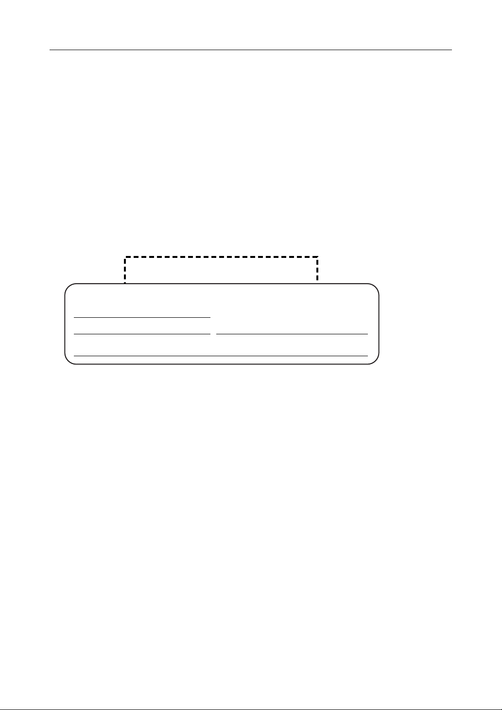
1.2 Included Accessories
The following items are provided with this product. Additional pieces can be ordered by calling 1-800332-5368.
Main unit ........................1 pc. AC adaptor..................... 1 pc.
(Cord length: approx. 3 m (9.8
feet))
Order No. PQLV202Y
Ethernet® cable (category 5
straight cable).................1 pc.
(Cable length: approx. 1 m
(1.1 yards))
Order No. PQJA10138Z
Stand .............................1 pc.
Order No. PQYLHGW502
AC cord ......................... 1 pc.
(Cord length: approx. 1.8 m
(5.9 feet))
Order No. PSJA1069Z
CD-ROM........................ 1 pc.
(Operating Instructions etc.)
Order No. PSQX3487XCD
• Installation/Troubleshooting - 1 pc.
• Warranty - 1 pc.
Accessories to be Provided by Customer
• Ethernet Cable (category 5 straight cable) - 1 pc.
•Network Camera
•PC
8
Page 9
Operating Instructions
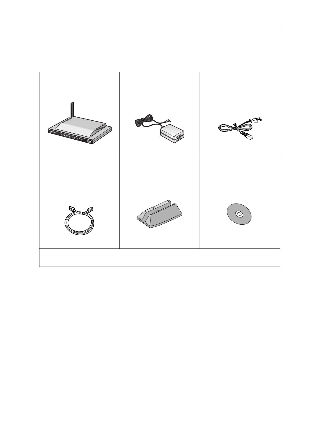
1.3 Feature Locations
1.3.1 Front View
POWER Indicator
(see page 10)
WAN Indicator
(see page 10)
PPPoE Indicator
(see page 10)
Introduction
Product
WIRELESS Indicator
(see page 10)
LAN1-LAN4 Indicators
(see page 10)
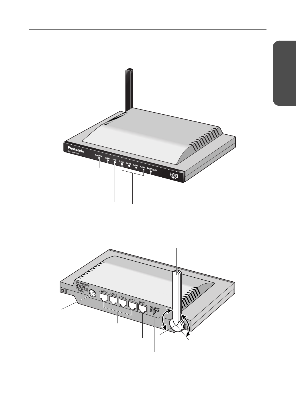
1.3.2 Rear View
DC IN Jack
(see Installation/Troubleshooting)
LAN1-LAN4 Jacks
(see Installation/Troubleshooting)
(see Installation/Troubleshooting)
WAN Jack
Diversity Antenna
The antenna rotates 100 degrees
clockwise and counterclockwise,
200 degrees in total.
100 ˚
FACTORY DEFAULT RESET Button
(see page 117)
100 ˚
9[For assistance, please call: 1-800-272-7033]
Page 10
Operating Instructions
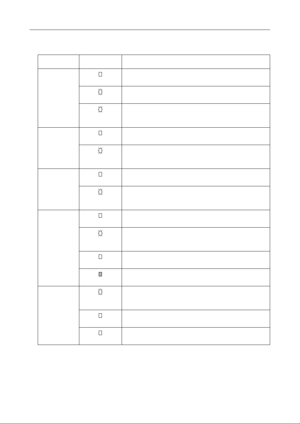
1.3.3 Indicators
Indicators Light Color Description
POWER
WAN
LAN1—LAN4
WIRELESS
Green
Red (Blinking)
Green
(Blinking)
Green
Green
(Blinking)
Green
Green
(Blinking)
Green
Green
(Blinking)
This product is turned on.
There is a problem with this product.
Remove the AC cord from the outlet, and insert again.
The firmware is damaged.
Download a firmware file (see page 31 - Installation/
Troubleshooting).
This product is successfully connected to a modem or an
Ethernet hub etc.
This product is connected and sending or receiving data.
This product is successfully connected to a PC or Ethernet
hub.
This product is sending or receiving data.
This product is successfully connected to a wireless device.
This product is sending or receiving data in a wireless LAN.
10
PPPoE
Orange
No light
Green
(Blinking)
Green
Orange
This product is not connected to a wireless device.
The communication mode is set to disabled, and the wireless
LAN is not being used. (see page
PPPoE connection is in progress.
PPPoE connection is complete.
A PPPoE authentication error has occurred.
48)
Page 11
2 Accessing This Product
2.1 Functions
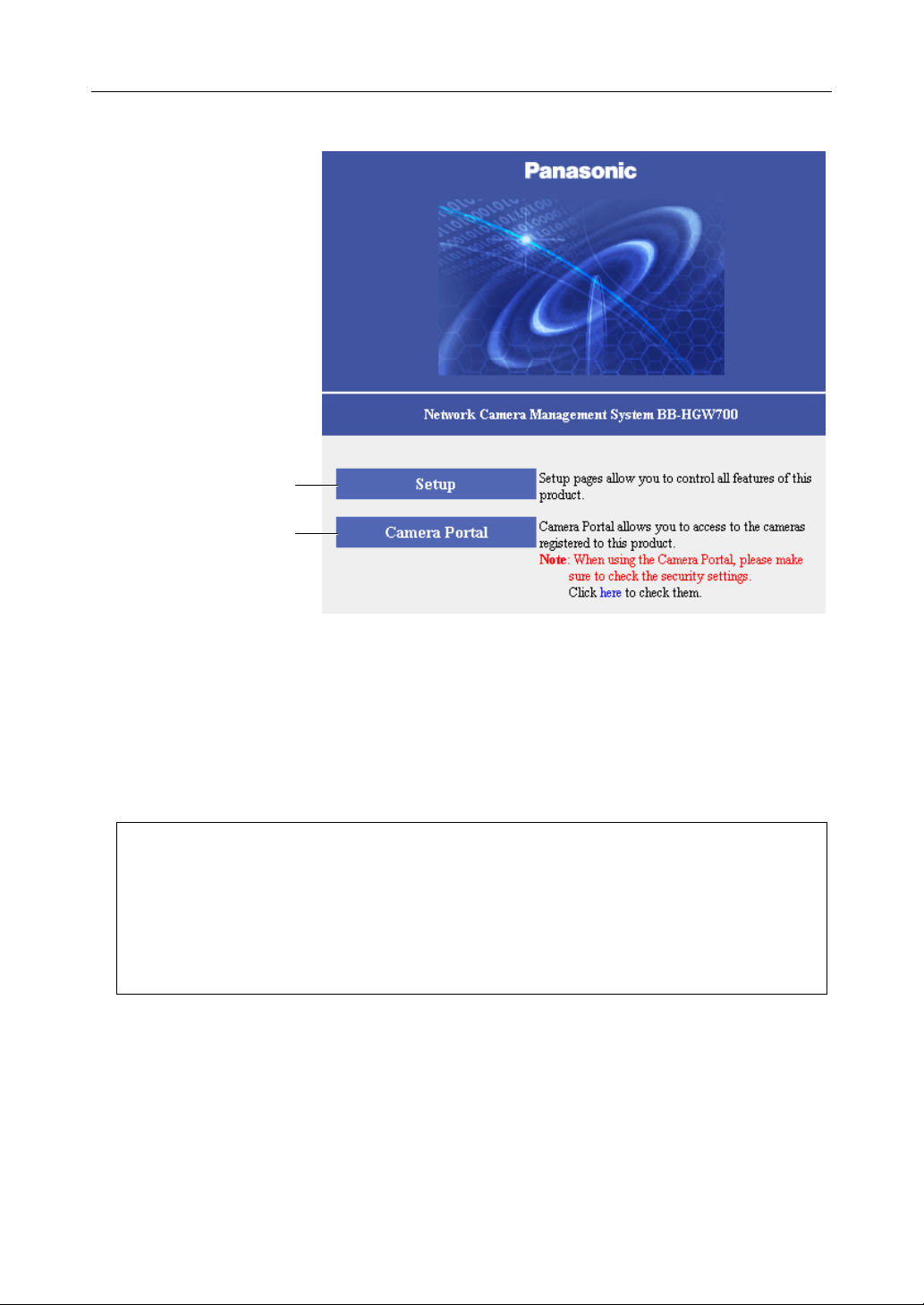
2.1.1 Top Page
The top page allows you to select the Setup page or Camera Portal page.
The Camera Portal page displays the images of the camera connected to this product.
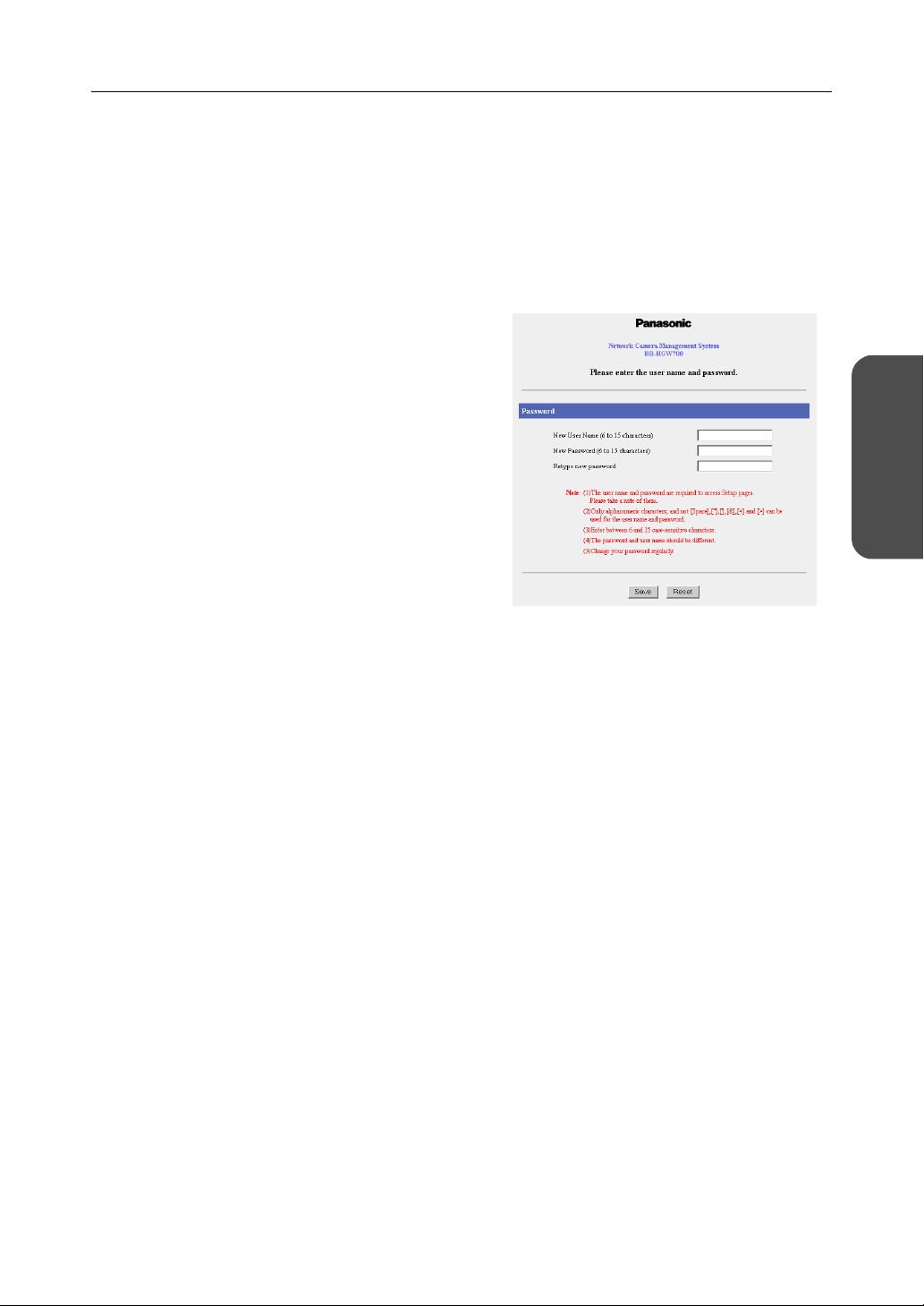
1. Enter "http://bbhgw.webpage:8080" into the
web browser's address bar
number is 8080
• The user name and password window is
displayed.
.)
. (The default port
Operating Instructions
This Product
Accessing
2. Enter New User Name, New Password, and
Retype New Password and click [Save].
• The top page is displayed.
Notes
• It is important to always use your user name and password for authentication when using
this product.
• Access information (user name/password), this product's setup information, application
setup information, logs and other system management information is the responsibility of
the customer. Access to this information should be limited to users or user groups, and third
parties should not be allowed to refer to, modify, delete or copy this information. Information
such as user name, password, setup and management information should be kept
confidential.
11[For assistance, please call: 1-800-272-7033]
Page 12
Operating Instructions
Setup (see page 13)
Camera Portal
(see page
17)
Notes
• In the default settings, it is possible to display the top page by entering "http://192.168.0.254:8080"
into the web browser's address bar.
• When accessing Setup from the top page, an authentication window is displayed (after starting the
web browser, first time only). Log in by entering your user name and password and clicking [OK].
• In order to view the camera images on the Camera Portal page of this product, it is necessary to
have completed a connection with a compatible camera (Customer-provided). See the camera's
manuals for more details.
.
If the top page is not displayed...
• Confirm that "http://bbhgw.webpage:8080" is entered correctly in the address bar (the
default port number is 8080). If the address is correct and the top page is still not displayed
enter "http://192.168.0.254:8080".
• Confirm that the LAN indicator corresponding to the jack connected to this product is on.
• Confirm that this product's power was turned on before the PC's power was.
• Sometimes it is necessary to set up the web browser's proxy server to access the top page
(see page
131).
12
Page 13
Operating Instructions
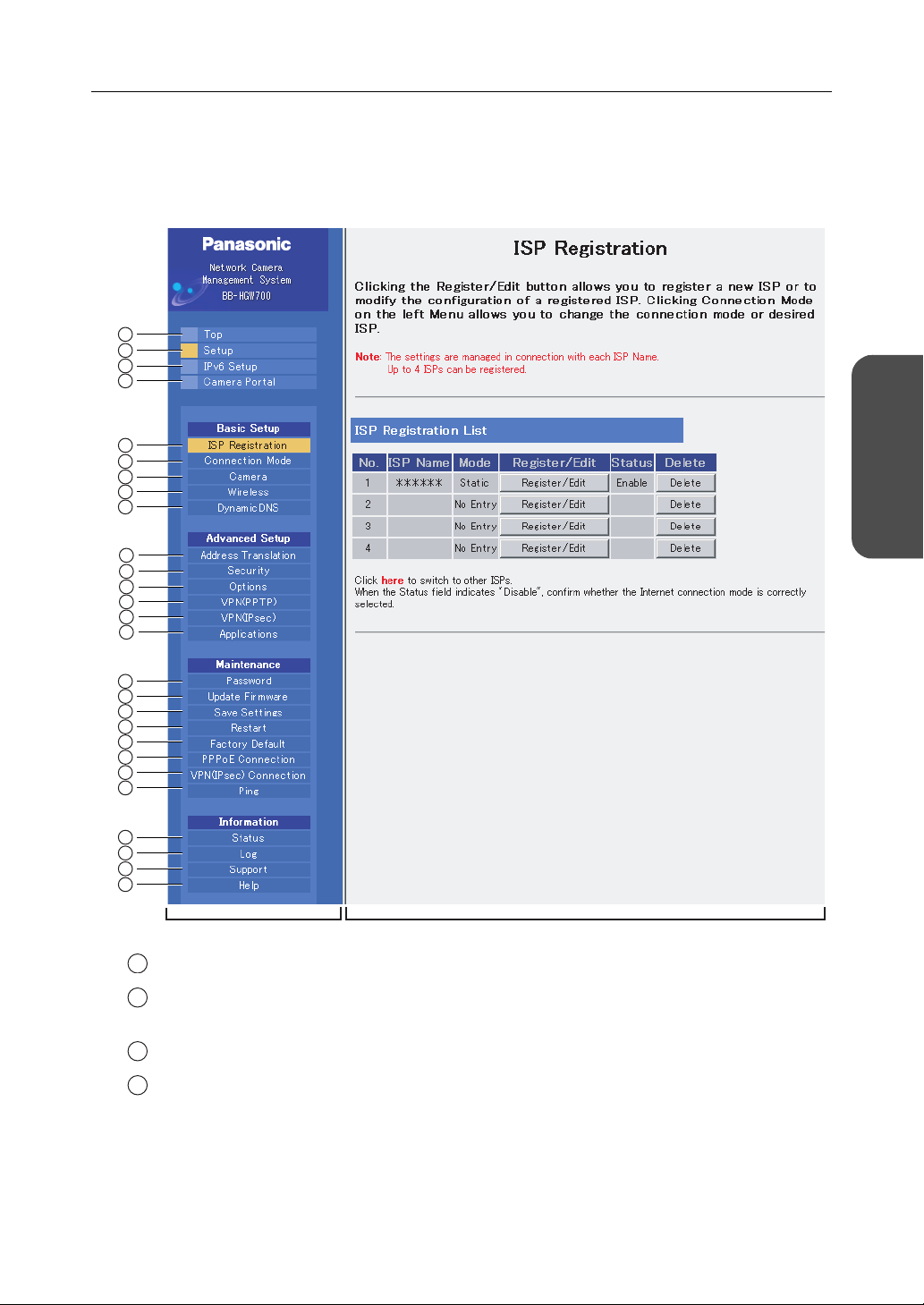
2.1.2 Setup
This page allows you to set up an IPv4 Internet connection using your PC's web browser.
The heading selected on the menu page is displayed on the main page.
The help page describes the operations of each heading.
1
2
3
4
5
6
7
8
9
10
11
12
13
14
15
This Product
Accessing
16
17
18
19
20
21
22
23
24
25
26
27
Menu Main
1
To p : Displays the top page. (see page 11)
2
Setup: Displays the setup page. It is possible to set up all operations from
this page. (see this page)
3
IPv6 Setup: Displays the IPv6 setup page. (see page 16)
4
Camera Portal: Allows you to view images from the camera registered on this
product. (see page
17)
13[For assistance, please call: 1-800-272-7033]
Page 14

Operating Instructions
Basic Setup
5
ISP Registration: Basic setup to connect to the Internet. (see page 22)
6
Connection Mode: Sets the connecting ISP. (see page 38)
7
Camera: Performs automatic camera registration setup and manual
8
Wireless: Sets up wireless LAN motion mode and wireless security. (see page
9
DynamicDNS Sets up DynamicDNS. (see page 56)
Advanced Setup
10
Address Translation: Translates both the global address on the WAN side (Internet) and
11
Security: Allows you to set up filtering, and control access to this product at
12
Options: Sets up access on the LAN side, and also connection to the Internet.
registration adding and deletion. (see page
40)
48)
private address on the LAN side, and also performs setup to access
this product's network from an Internet terminal. (see page
the touch of a button, and automatically saves a log. (see page
(see page
77)
60)
66)
13
VPN (PPTP): By setting a user name and password, this product allows you to
create a VPN (Virtual Private Network) using PPTP (Point-to-Point
Tunneling Protocol). (see page 88)
14
VPN (IPsec) By setting security policy database, this product allows you to create
a VPN using IPsec. (see page
15
Applications: This function allows you to register, execute and delete applications
for use with this product. (see page
90)
98)
Maintenance
16
Password: Modifies the user name and password to access the setup page.
(see page
17
Update Firmware*: Updates to the latest version of firmware. (see page 102)
18
Save Settings: Saves and loads settings. (see page 104)
19
Restart: Restarts this product. (see page 105)
20
Factory Default: Initializes this product. The settings are returned to the factory
default. (see pages
21
PPPoE Connection: Manually starts or stops the PPPoE connection to the ISP. (see page
101)
105 and 117)
106)
22
VPN (IPsec)
Connection
Manually starts or stops the VPN (IPsec) connection to the ISP. (see
107)
page
14
23
Ping: Checks that each device with an IP address is connected. (see page
108)
Page 15

Operating Instructions
Information
24
Status: Displays information such as connection status. (see page 109)
25
Log: Displays Filtering Log, UPnP Log (general), UPnP Log (CP),
Connection Log, DynamicDNS Log, VPN (PPTP) Connection Log,
VPN (IPsec) Connection Log, Mail Transmission Log, and VPN (IPv4
IPsec) Connection Log. (see page
26
Support: Product and support information can be found on the Internet. (see
page
116)
27
Help: Explains about commands and functions on the setup pages. (see
page
116)
112)
* To download the latest version of the firmware from Panasonic's support website, it is necessary
to connect to the Internet.
This Product
Accessing
15[For assistance, please call: 1-800-272-7033]
Page 16
Operating Instructions
2.1.3 IPv6 Setup
This page allows you to set up an IPv6 Internet connection using your PC's web browser.
The heading selected on the menu page is displayed on the main page.
The Help page describes the operations of each heading.
1
2
3
Menu Main
1
IPv6 ISP Registration: IPv6 basic setup to connect to the Internet. (see page 30)
2
IPv6 Security: Allows you to set up IPv6 filtering, and control access to this
product at the touch of button, and automatically saves a log. (see
72)
page
3
IPv6 Options: Sets up access on the LAN side, and various other IPv6 options.
(see page
85)
16
Page 17
Operating Instructions
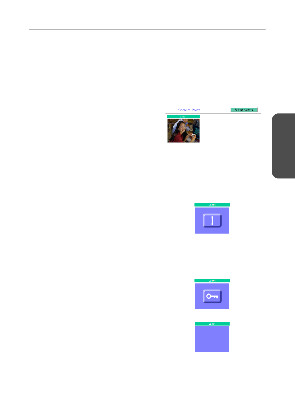
2.1.4 Camera Portal
This product has a built in web server function. Camera Portal allows you to list up to 16 cameras
names and their still images.
Viewing Camera Images from the LAN (Home) Side
It is possible to view camera images by accessing the camera portal.
1. Start the web browser.
2. Enter "http://bbhgw.webpage:port number"
into the web browser's address bar.
• (e.g. http://bbhgw.webpage:80
The default port number is 80. If the port
number is 80, there is no need to enter it.)
• The camera portal is displayed.
• By clicking on the still image, a single
moving image can be displayed.
• When Microsoft
Pack 2 is used, a pop-up blocker may
prevent the camera from displaying the
image. See page 118 about a pop-up
blocker.
®
Windows XP Service
This Product
Accessing
Notes
• If an exclamation mark is displayed, click it
and the camera's password window is
displayed. Perform the settings on each
page. Setting Allow Access from the
Internet to Enable, displays the camera
images on the Camera Portal over the
Internet. Setting Disable only displays the
camera images on the Camera Portal when
accessing from the LAN side.
(It is displayed when a factory default
camera is connected.)
• If a key mark is displayed, click it and enter
that camera's user name and password.
(If camera authentication has been set up,
the key mark will be displayed.)
• A blue unmarked window is displayed when
the camera is outside operation time. If a
blue unmarked window is displayed even
when the camera is operating, click
[Refresh Camera].
(The blue unmarked window may be
displayed when authentication is being
confirmed.)
17[For assistance, please call: 1-800-272-7033]
Page 18
Operating Instructions
• If the camera and this product are
disconnected while sending or receiving
data, a key mark (when camera
authentication is set up) or a blue
unmarked window is displayed. In this
case, after checking that the camera's
power supply and connections are correctly
inserted, click [Refresh Camera].
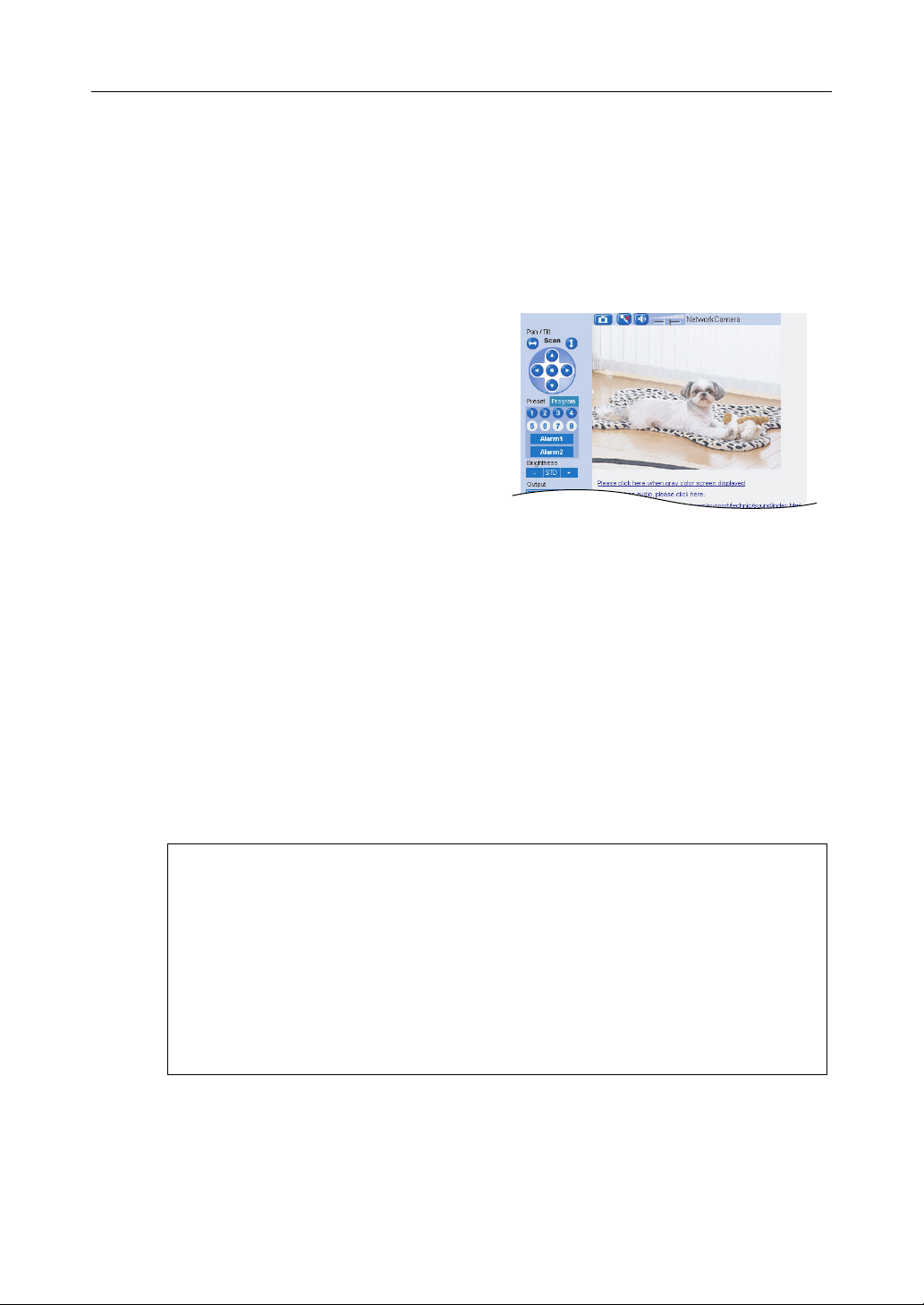
3. Click the camera frame you want to access.
• If an authentication window is displayed,
enter the camera's user name and
password. Then the camera image is
displayed.
Notes
• When refreshing the camera portal, click [Refresh Camera] on the Camera Portal page.
• After entering the camera's user name and password and displaying the camera image
once, the camera image will be displayed on the camera portal without the key mark. When
displaying other pages such as setup, the key mark will return, but by clicking it, the camera
image will be displayed without the authentication window.
Privacy and Image Right
When installing and using this camera, it is the customers responsibility to not infringe on
privacy or copyright rules and regulations.
* It is generally accepted that "Privacy is the legal right to not have one's private life displayed
in public, and the right to have control over one's own personal information. Image right is
the right to not have portraits or photographic images of one's self created by a stranger or
displayed in public".
When camera images are not displayed on the camera portal...
• Check that the WAN indicator and the LAN indicator corresponding to the jack
connected to this product is on.
• Sometimes it is necessary to set up the web browser's proxy server to access the
camera portal (see page
• Check that the power supply was turned on in the following order: modem, this
product, PC.
• When a camera name, an X mark, a blue unmarked window, or a white page is
displayed on the camera portal, click [Refresh Camera].
• When an exclamation mark is displayed on the camera portal, click it. The camera's
password window is displayed.
131).
18
Page 19

Operating Instructions
Viewing Camera Images from the WAN (Internet) Side
This function allows you to view camera images by accessing the camera portal from the WAN side.
Note
To view camera images from the Internet, it is necessary to connect this product to your modem
and have an Internet subscription. Regarding how to connect to the Internet see Installation/
Troubleshooting and Using the Functions (see page 22).
1. Start the web browser.
2. Enter "http:// IP address(WAN) or URL : port
number" into the web browser's address bar.
• (e.g. http://10.75.68.251:80
http://www.example.com:80
The default port number is 80. If the port
number is 80, there is no need to enter it.)
Notes
• It is possible to check the status of the IP address (WAN) on the setup pages. (see page 109)
• When using this product with a service that is not a static IP service, the IP address
changes. It is recommended that you use the Viewnetcam.com service. (see page
56)
3. Press [Enter].
• The camera portal is displayed.
• By clicking on the still image, a single
moving image can be displayed.
• When Microsoft Windows XP Service Pack
2 is used, a pop-up blocker may prevent the
camera from displaying the image. See
page 118 about a pop-up blocker.
Notes
• In order to open an IPv6 camera with an
IPv6 address using the Camera Portal, first,
register the camera's IPv6 address with an
IPv6 compatible DynamicDNS service (e.g.
Viewnetcam.com). Then, register the
camera manually on this product (To
register a domain name to the IPv6 camera
settings, see page 44), and set it on the
Camera Portal.
• In order to use IPv6 your local network,
your ISP must support IPv6. Please contact
your local network administrator or ISP if
you have any questions.
This Product
Accessing
19[For assistance, please call: 1-800-272-7033]
Page 20
Operating Instructions
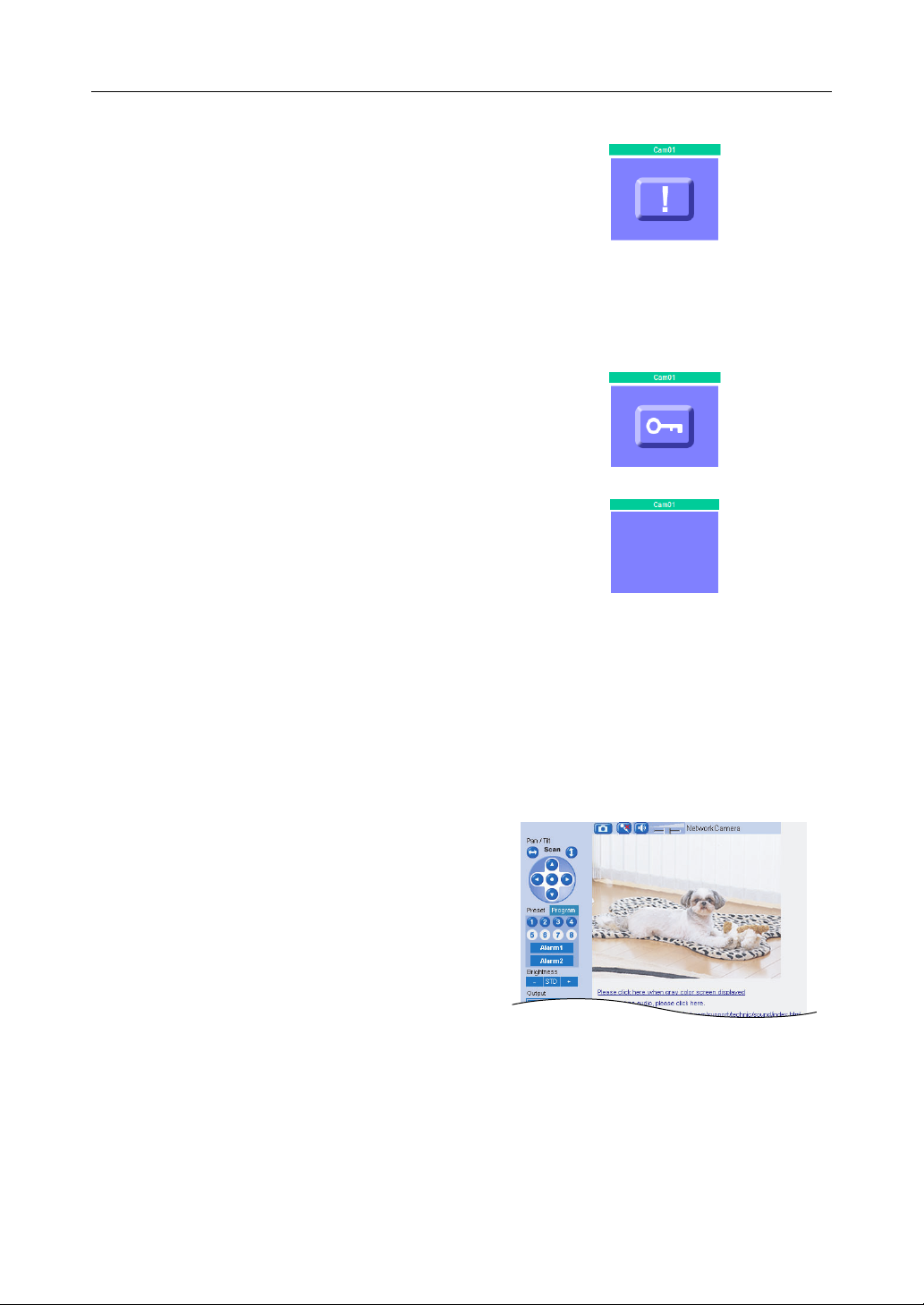
• If an exclamation mark is displayed, click it
and the camera's password window is
displayed. Perform the settings on each
page. Setting Allow Access from the
Internet to Enable, displays the camera
images on the Camera Portal over the
Internet. Setting Disable only displays the
camera images on the Camera Portal when
accessing from the LAN side.
(It is displayed when a factory default
camera is connected.)
• If a key mark is displayed, click it and enter
that camera's user name and password.
(If camera authentication has been set up,
the key mark will be displayed.)
• A blue unmarked window is displayed when
the camera is outside operation time. If a
blue unmarked window is displayed even
when the camera is operating, click
[Refresh Camera].
(The blue unmarked window may be
displayed when authentication is being
confirmed.)
• If the camera and this product are
disconnected while sending or receiving
data, a key mark (when camera
authentication is set up) or a blue
unmarked window is displayed. In this
case, after checking that the camera's
power supply and connections are correctly
inserted, click [Refresh Camera].
4. Click the camera frame you want to access.
• If an authentication window is displayed,
enter the camera's user name and
password. Then the camera image is
displayed.
20
Page 21

Operating Instructions
If the camera portal is not displayed...
• Check that "http:// IP address(WAN) or URL : port number" was entered correctly
into the address bar.
• Sometimes it is necessary to set up the web browser's proxy server to access the
website. (see page
• When a camera name, an X mark, or a white page is displayed on the camera portal,
click [Refresh Camera].
Notes
• All user information (video images, still images, Internet contents etc.) is the responsibility
of the customer. Access to this information should be limited to users or user groups, and
third parties should not be allowed to refer to, modify, delete or copy this information.
• When changing the setup of the camera or camera portal, see Using Camera. (see page 40)
Privacy and Image Right
When installing and using this camera, it is the customers responsibility not to infringe on
privacy or copyright rules and regulations.
131)
* It is generally accepted that "Privacy is the legal right not to have one's private life displayed
in public, and the right to have control over one's own personal information. Image right is
the right to not have portraits or photographic images of one's self created by a stranger or
displayed in public".
This Product
Accessing
21[For assistance, please call: 1-800-272-7033]
Page 22
Operating Instructions
3 Functions
3.1 Using the Functions
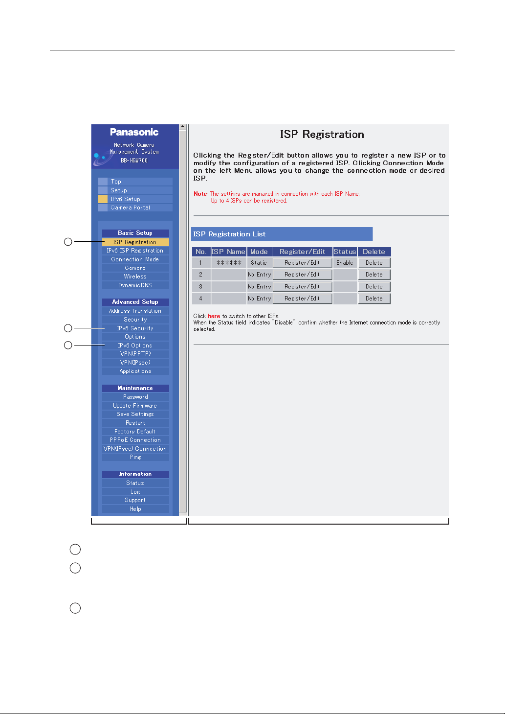
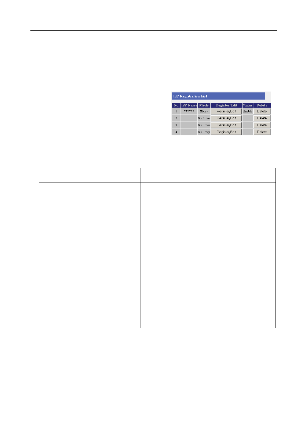
3.1.1 Registering ISPs
The ISP registration page allows you to register new
ISPs (see page
delete them (see page 29). Internet connection
methods vary according to the ISP. Select a
connection method referring to the ISP's setup
information.
Consult with your contracted ISP about which connection type to use, or about your service or contract.
Data Entry Field
23) for this product, edit them, and
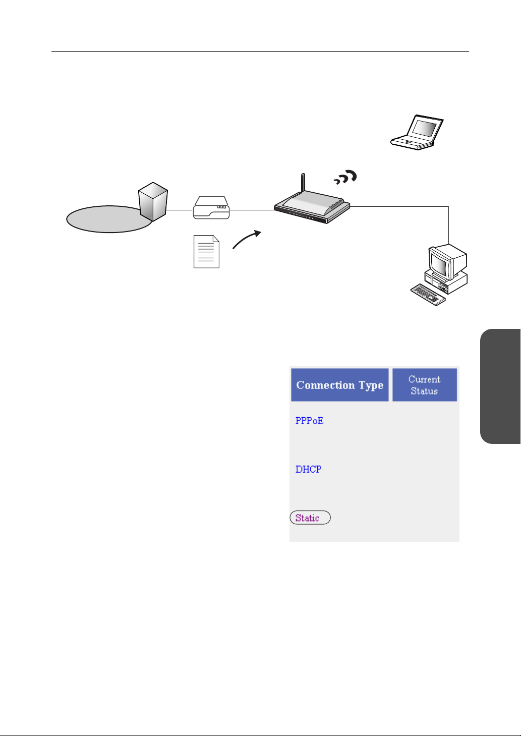
Connection Type Description
PPPoE (see page 23)
• ISP Name
•User Name/Password
•Service Name
• Access Concentrator Name
• DNS Server 1/DNS Server 2
• Domain Name
DHCP (see page 25)
• ISP Name
•Device Name
•Gateway
• DNS Server 1/DNS Server 2
• Domain Name
Static (see page 27)
• ISP Name
• IP Address
• Subnet Mask
•Gateway
• DNS Server 1/DNS Server 2
• Domain Name
It is necessary to enter the following data when using
PPPoE connection. Enter the user name and
password referring to the ISP's setup information.
Enter the service name, access concentrator name
DNS server 1, DNS server 2, and/or domain name if
specified by the ISP.
When the ISP is using a DHCP server, setup entry is
not essentially necessary. However, sometimes it is
necessary to enter the device name, gateway, DNS
server 1, DNS server 2, and/or domain name. Enter
them referring to your ISP's setup information.
Enter the IP address, subnet mask, gateway, DNS
server 1, and DNS server 2 specified by the ISP. Enter
the domain name if specified by the ISP.
* If it is not necessary to enter information into the data entry field, leave it blank.
22
Page 23
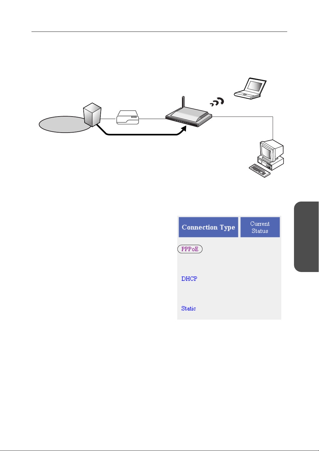
PPPoE Connection
Follow the steps below to set up PPPoE connection.
ISP
Modem
Internet
The ISP assigns an IP address
by PPPoE connection.
1. Select [ISP Registration].
2. Click [Register/Edit] on the ISP registration list.
Operating Instructions
Private address
192.168.0.2
Private address
192.168.0.1
Functions
3. Select PPPoE.
23[For assistance, please call: 1-800-272-7033]
Page 24
Operating Instructions
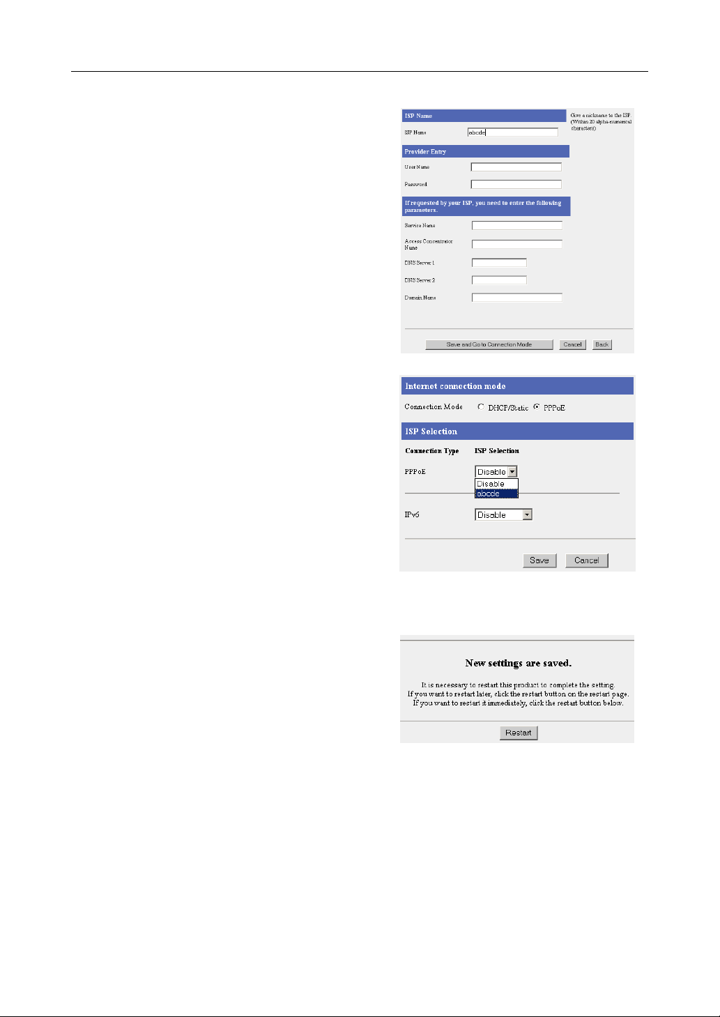
4. Enter ISP Name.
• Enter no more than 20 characters. In the
example right, "abcde" has been entered.
5. Enter User Name and Password, and if
specified by the ISP
Access Concentrator Name, DNS Server 1,
/or Domain Name.
and
• See the ISP's setup information. To return
to the original settings, click [Cancel].
, enter Service Name,
6. When setup is complete, click [Save and Go to
Connection
• The connection mode page is displayed.
Mode].
7. Select the ISP entered in step 4.
2,
8. When setup is complete, click [Save].
• The entered information is saved.
Note
When saving, do not cut the power supply. If cut, saving might not be completed successfully.
9. When [Restart] is displayed on the setup page,
.
click it
10. Restart the PC.
• Check that the PC is connected to the
Internet. (see page 37)
Notes
• When registering or editing, restart all PCs connected to the LAN (home) side.
• When adding more PCs after setup has been completed, connect the new PCs to jacks
LAN1 to LAN4 and then restart.
• When instructed by your ISP, change the MTU value. When not instructed, leave it as the
default (1492). (see page
80)
24
Page 25
Operating Instructions
s
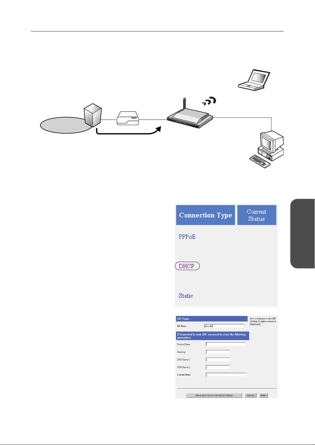
DHCP Connection (Internet Connection using a DHCP Server)
Follow the steps below to set up DHCP connection, where an IP address is automatically allocated by
the ISP.
ISP
Modem
Internet
The ISP's DHCP Server
assigns an IP address.
1. Select [ISP Registration].
2. Click [Register/Edit] on the ISP registration list.
3. Select DHCP.
Private address
192.168.0.2
Private addres
192.168.0.1
Functions
4. Enter ISP Name.
• Enter no more than 20 characters. In the
example right, "abcde" has been entered.
5. If specified by the ISP, enter Device Name*,
Gateway, DNS Server 1,
.
Name
• See the ISP's setup information. To return
to the original settings, click [Cancel].
2, and/or Domain
* The device name is sometimes said by the
ISP to be the ID entered into the PC's
Computer Name entry field.
25[For assistance, please call: 1-800-272-7033]
Page 26
Operating Instructions
6. When setup is complete, click [Save and Go to
Connection
• The connection mode page is displayed.
Mode].
7. Select the ISP entered in step 4.
8. When setup is complete, click [Save].
• The entered information is saved.
Note
When saving, do not cut the power supply. If cut, saving might not be completed successfully.
9. When [Restart] is displayed on the setup page,
.
click it
10. Restart the PC.
• Check that the PC is connected to the
Internet. (see page 37)
Notes
• When registering or editing, restart all PCs connected to the LAN (home) side.
• When adding more PCs after setup has been completed, connect the new PCs to jacks
LAN1 to LAN4 and then restart.
26
Page 27
Operating Instructions
Static Connection (Internet Connection using a Static IP Address)
It may be necessary, if you are instructed by the ISP, to enter the value of the IP address or gateway
address into setup information.
Private address
ISP
Modem
Internet
Static IP Address
An IP address is set based
on information from the ISP.
192.168.0.2
Private address
192.168.0.1
1. Select [ISP Registration].
2. Click [Register/Edit] on the ISP registration list.
3. Select Static.
Functions
27[For assistance, please call: 1-800-272-7033]
Page 28
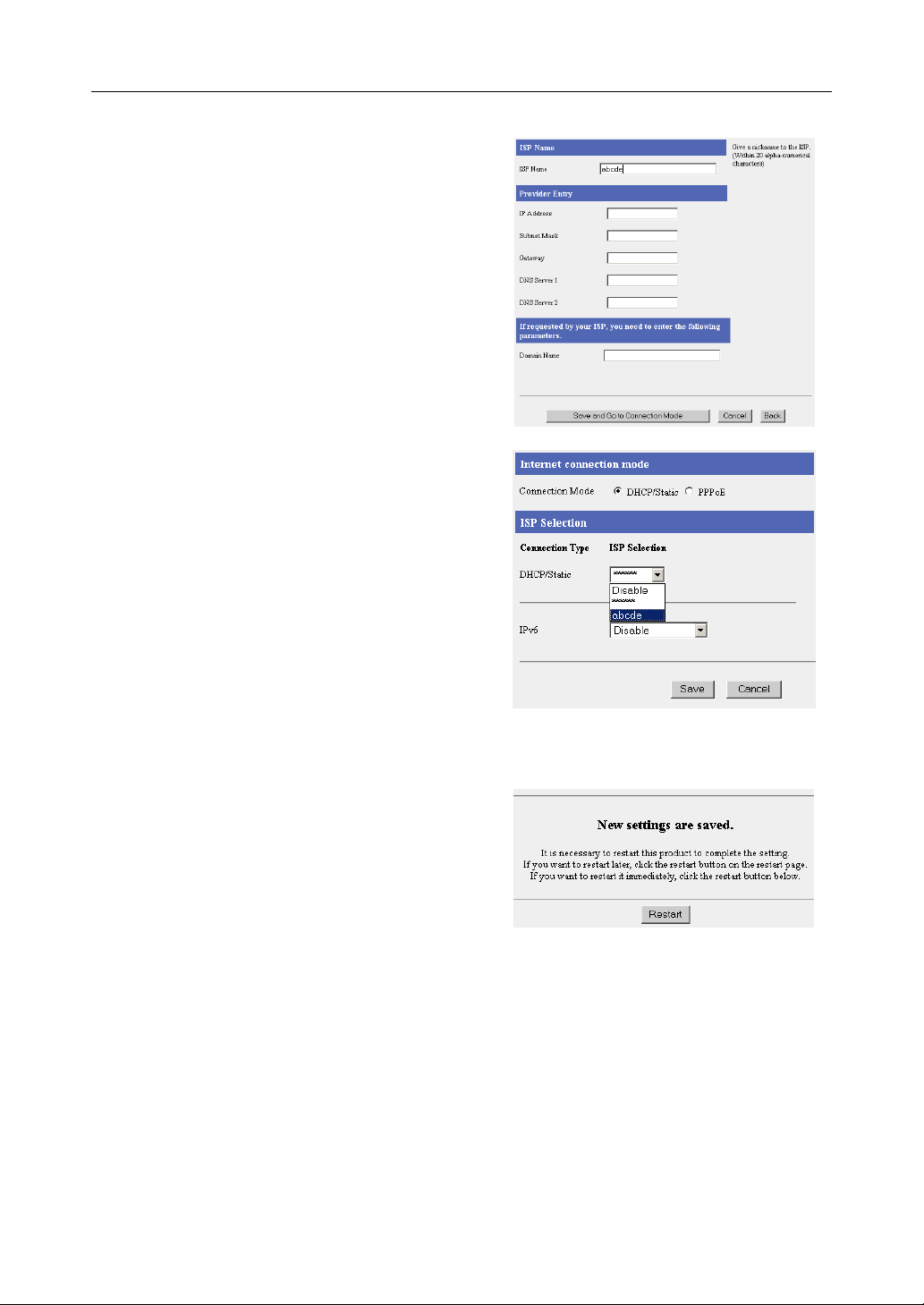
Operating Instructions
4. Enter ISP Name.
• Enter no more than 20 characters. In the
example right, "abcde" has been entered.
5. Enter the IP Address, Subnet Mask, Gateway
and DNS server 1, 2, and if specified by the
ISP, enter the Domain Name.
• See the ISP's setup information. To return
to the original settings, click [Cancel].
6. When setup is complete, click [Save and Go to
Connection
• The connection mode page is displayed.
Mode].
7. Select the ISP entered in step 4.
8. When setup is complete, click [Save].
• The entered information is saved.
Note
When saving, do not cut the power supply. If cut, saving might not be completed successfully.
9. When [Restart] is displayed on the setup page,
.
click it
10. Restart the PC.
• Check that the PC is connected to the
Internet. (see page 37)
Notes
• When registering or editing, restart all PCs connected to the LAN (home) side.
• When adding more PCs after setup has been completed, connect the new PCs to jacks
LAN1 to LAN4 and then restart.
28
Page 29
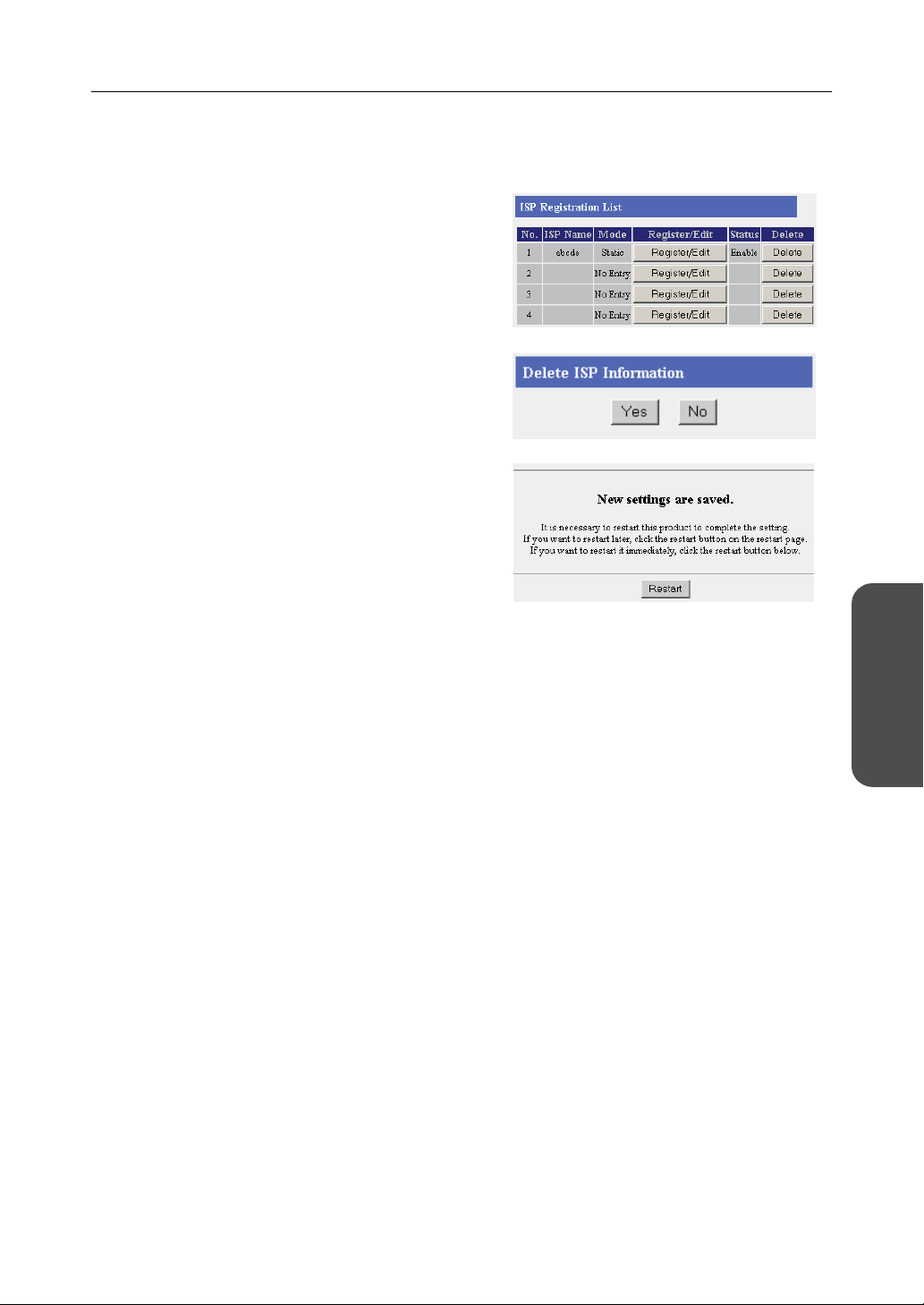
Operating Instructions
ISP Deletion
Follow the steps below to delete ISPs from the ISP registration list/IPv6 ISP Registration List.
1. Click [Delete] on the row of the ISP you want to
.
delete
• The ISP deletion confirmation window is
displayed.
2. Click [Yes].
• To cancel the deletion click [No].
3. When [Restart] is displayed on the setup page,
click it.
Functions
29[For assistance, please call: 1-800-272-7033]
Page 30

Operating Instructions
3.1.2 Registering IPv6 ISPs
This heading is only displayed when IPv6 Setup is
selected on the menu. On the IPv6 ISP Registration
List it is possible to register, edit and delete IPv6 ISPs
to connect to this product. Methods of connection to
the IPv6 network are different depending on the ISP.
Select a connection type referring to information from
your ISP.
Consult with your contracted ISP about which IPv6 connection type to use, or about your service or
contract.
Data Entry Field
Connection Type Description
Tunneling (see page 31)
• ISP Name
• Destination IP Address
•Prefix(LAN)
• IPv6 DNS Server 1/
IPv6 DNS Server 2
• IPv6 Address(WAN)
6to4 (see page 33)
• ISP Name
• Destination IP Address
Static v6 (see page 35)
• ISP Name
• IPv6 address(WAN)
•Prefix(LAN)
•IPv6 Default Gateway
• IPv6 DNS Server 1/
IPv6 DNS Server 2
• Domain Name
Enter the Destination IP Address and Prefix(LAN)
specified by the ISP. Enter the IPv6 DNS Server 1,
IPv6 DNS Server 2, and/or IPv6 Address(WAN) if
specified by the ISP.
6to4 is a connection mode being used experimentally
to verify the mutual connectivity of IPv4 and IPv6.
Set the destination IP address seeing the website
describing 6to4 addressing.
Enter the IPv6 Address(WAN), Prefix(LAN), IPv6
Default Gateway, IPv6 DNS Server 1, and IPv6 DNS
Server2 specified by the ISP. Enter Domain Name if
specified by the ISP.
* If it is not necessary to enter information into the data entry field, leave it blank.
What is IPv6?
• IPv6 is short for "Internet Protocol Version 6".
• IPv6 was created to address the additional IP addresses that will be needed as the Internet
continues to expand.
• IPv6 is expected to gradually replace IPv4, with the 2 coexisting for a number of years during a
transition period.
• Though most ISPs (Internet Service Providers) do not yet support IPv6, many local networks
already use it. When your ISP supports IPv6, your Panasonic Network Camera Management
System will be ready!
• For more information you wish to visit http://www.ipv6.org/.
30
Page 31

Operating Instructions
Tunneling Connection
It is possible to encapsulate IPv6 packets with IPv4 packets and perform IPv6 communication on a
IPv4 network. Take the following steps to set up tunneling connection.
Internet
IPv6 IPv4 IPv6
1. Select [IPv6 ISP Registration].
2. Click [Register/Edit] on the IPv6 ISP
registration list.
3. Select Tunneling.
4. Enter ISP Name.
• Enter no more than 20 characters. In the
example right, "abcde" has been entered.
5. Enter the Destination IP Address and
Prefix(LAN)
the IPv6 DNS Server 1, IPv6 DNS Server 2,
and/or IPv6 Address(WAN).
• See the ISP's setup information. To return
to the original settings, click [Cancel].
, and if specified by the ISP, enter
6. When setup is complete, click [Save and Go to
Connection Mode].
• The connection mode page is displayed.
Functions
31[For assistance, please call: 1-800-272-7033]
Page 32

Operating Instructions
7. Select the ISP entered in step 4.
8. When setup is complete, click [Save].
• The entered information is saved.
Note
When saving do not cut the power supply. If cut, saving might not be completed successfully.
9. When [Restart] is displayed on the setup page,
click it.
10. Restart the PC.
• Check that the PC is connected to the
Internet. (see page 37)
Notes
• When registering or editing, restart all PCs connected to the LAN (home) side.
• When adding more PCs after setup has been completed, connect the new PCs to jacks
LAN1 to LAN4 and then restart.
32
Page 33

Operating Instructions
6to4 Connection
6to4 is a type of tunnel connection which can be used experimentally. 6to4 encapsulates IPv6 packets
with IPv4 packets, and connects to the IPv6 network through the 6to4 relay router. It is not necessary
to subscribe to an ISP for this type of connection. Take the following steps to set up 6to4 connection.
1. Select [IPv6 ISP Registration].
2. Click [Register/Edit] on the IPv6 ISP
registration list.
3. Select 6to4.
4. Enter ISP Name.
• Enter no more than 20 characters. In the
example right, "abcde" has been entered.
5. Set the destination router's IPv4 Address.
• To return to the original settings, click
[Cancel].
Note
Set a public 6to4 relay router IP address for the destination IP address. The 6to4 relay router
is made public and can search the Internet.
Functions
6. When setup is complete, click [Save and Go to
Connection Mode].
• The connection mode page is displayed.
7. Select the ISP entered in step 4.
8. When setup is complete, click [Save].
• The entered information is saved.
Notes
• When saving, do not cut the power supply. If cut, saving might not be completed
successfully.
• You must set an IPv4 ISP.
• The WAN side IPv6 global address may change when the WAN side IPv4 global address is
changed, because 6to4 connection is dependent upon the IPv4 global address.
33[For assistance, please call: 1-800-272-7033]
Page 34

Operating Instructions
9. When [Restart] is displayed on the setup page,
click it.
10. Restart the PC.
• Check that the PC is connected to the
Internet. (see page 37)
Notes
• When registering or editing, restart all PCs connected to the LAN (home) side.
• When adding more PCs after setup has been completed, connect the new PCs to jacks
LAN1 to LAN4 and then restart.
34
Page 35

Operating Instructions
Static v6 Connection
This function allows you to communicate directly using IPv6. To set up static v6 connection, take the
following steps.
IPv6 Network
Internet
ISP
1. Select [IPv6 ISP Registration].
2. Click [Register/Edit] on the IPv6 ISP
registration list.
3. Select Static v6.
4. Enter ISP Name.
• Enter no more than 20 characters. In the
example right, "abcde" has been entered.
5. Enter the IPv6 Address(WAN), Prefix(LAN),
IPv6 Default Gateway, IPv6 DNS Server 1, and
IPv6 DNS Server2, and if specified by the ISP,
enter the Domain Name.
• See the ISP's setup information. To return
to the original settings, click [Cancel].
Functions
6. When setup is complete, click [Save and Go to
Connection Mode].
• The connection mode page is displayed.
7. Select the ISP entered in step 4.
35[For assistance, please call: 1-800-272-7033]
Page 36

Operating Instructions
8. When setup is complete, click [Save].
• The entered information is saved.
Note
When saving, do not cut the power supply. If cut, saving might not be completed successfully.
9. When [Restart] is displayed on the setup page,
click it.
10. Restart the PC.
• Check that the PC is connected to the
Internet. (see page 37)
Notes
• When registering or editing, restart all PCs connected to the LAN (home) side.
• When adding more PCs after setup has been completed, connect the new PCs to jacks
LAN1 to LAN4 and then restart.
• For deleting IPv6 ISPs, see page 29.
36
Page 37

Operating Instructions
3.1.3 Confirming Connection to the Internet
Confirming Connection
After the setup for Internet connection is complete, try to access a website. If the website is displayed,
you have successfully connected to the Internet.
1. Start the web browser.
2. Enter a website address into the web browser's
address bar
(e.g. http://www.panasonic.com), and press
[Enter]
• The website is displayed.
When a website is not displayed...
• Check that the website address was entered correctly in the web browser's address bar.
• Check that the WAN and LAN indicators corresponding to the WAN and LAN jacks
connected to this product are on.
• Check that the power supply was turned on in the following order: modem, this product,
PC.
• Sometimes it is necessary to set up the web browser's proxy server to access a website
(see page
.
131).
Functions
37[For assistance, please call: 1-800-272-7033]
Page 38

Operating Instructions
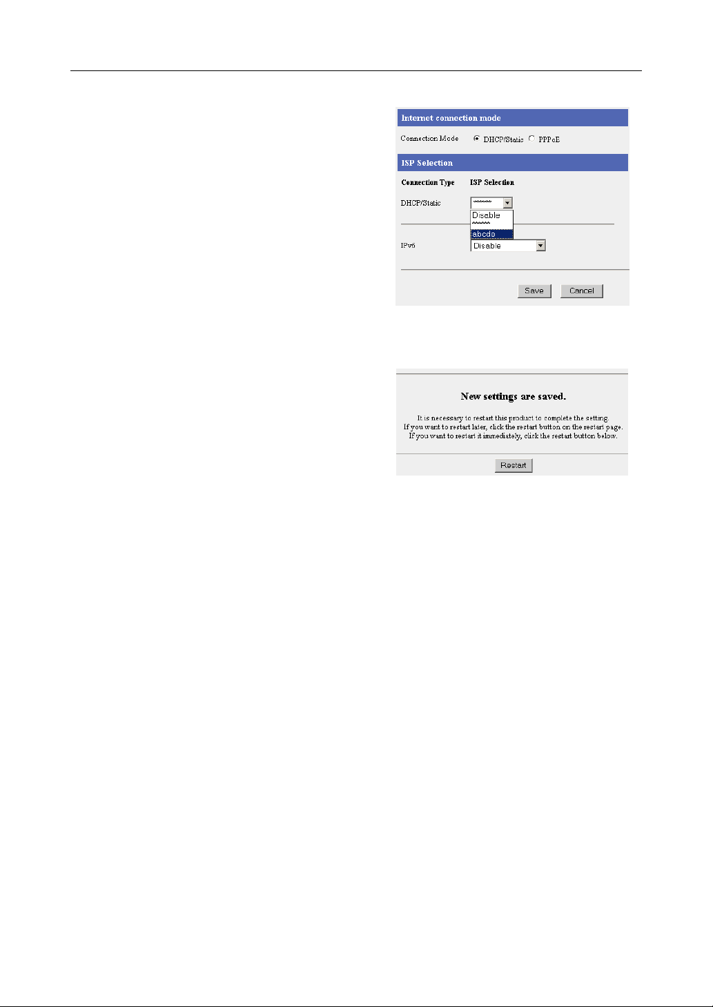
3.1.4 Managing the Connection Mode
The connection mode page allows you to switch between registered ISPs. On the connection mode
page, connecting ISPs which have been registered, can be selected from the LAN (Home) side to the
WAN (Internet) side.
The two types of connection mode for ISPs connecting to the WAN (Internet) side are [DHCP/Static]
and [PPPoE].
Setting up the DHCP/Static Connection Mode to the WAN (Internet)
Side
1. Click Connection Mode on the menu page.
• The connection mode page is displayed.
2. Confirm that DHCP/Static is selected as the
connection mode
• It is checked as factory default.
3. Select the ISP on the ISP selection dropdown
list
.
.
4. Click [Save].
• When setup is complete, the restart
window is displayed.
5. Click [Restart].
Data Entry Field
ISP Selection Select only one ISP to use. It is possible to select an IPv6 ISP if one is
registered.
38
Page 39

Operating Instructions
Setting up the PPPoE Connection Mode to the WAN (Internet) Side
1. Click Connection Mode on the menu page.
• The connection mode page is displayed.
2. Select PPPoE as the connection mode.
• ISP Selection is modified.
3. Select the ISP on the ISP selection dropdown
list
.
4. Click [Save].
• When setup is complete, the restart
window is displayed.
5. Click [Restart].
Data Entry Field
ISP Selection Select only one ISP to use. It is possible to select an IPv6 ISP if one is
registered.
Functions
39[For assistance, please call: 1-800-272-7033]
Page 40

Operating Instructions
3.1.5 Using Camera
The camera page allows you to set up cameras connected to this product.
Usually it is not necessary to set up a camera because the automatic registration function of
Panasonic's Network Cameras sets up the camera name, port number, and IP address automatically.
When changing a camera name, follow the steps on page
registered cameras. Also, when manually setting up a camera network, register cameras by following
the steps in additional camera registration.
Automatic Setup
43 - changing the setup of automatically
Data Entry Field
Automatic Setup Select Enable or Disable.
IPv4 Camera
Available Address
Range
Port Number assigned
to network camera
Available Port Range Specify the camera por t number.
Specify one sequenced address range to be allocated to the
camera.
• Be careful that it does not overlap the address allocated by a
server, such as a DHCP/PPTP server.
• The default is 192.168.0.151 - 192.168.0.166.
Select Single port or By range.
• If By range is selected, the value of the Available Port Range is
automatically allocated.
• Single port can be used in the following situations:
1 When connecting the WAN side to an internal company
network, without using address translation.
2 When using only the LAN without connecting to the WAN
side.
• When selecting By range above, it is only possible to specify one
sequenced port number range. It is necessary to have the same
number of port numbers as available address ranges specified
above, so specify the port number range that you will use.
• When selecting Single port above, specify one static port
number.
• The default is 60001-60016.
40
Page 41

Operating Instructions
IPv6 Camera
Port
Specify the port number for the IPv6 camera.
• The specified port will be provided automatically to IPv6
cameras.
• The default is 80.
Functions
41[For assistance, please call: 1-800-272-7033]
Page 42

Operating Instructions
3.1.6 Registering a Camera Automatically
After connecting this product to a Panasonic Network Camera (Customer-provided), turning the
camera on, and returning the settings to factory default, the camera's network setup (IP address and
subnet mask etc.) and wireless security setup are performed automatically. After the camera is turned
on, this product and the camera exchange information and automatically set up the network. Then, the
camera image is registered on the Camera Portal.
Setup Headings
This Product Port Forwarding
Camera Registration
Screen Assignment
Camera Port Number (IPv4)
IP Address (IPv4)
Port Number (IPv6)
DNS Server Address (IPv4/IPv6)
Subnet Mask
Default Gateway (IPv4)
SSID (wireless LAN type only)
Encryption Key (wireless LAN type only)
Compatible cameras
(Customer-provided) :
(as of Mar. 2005)
Indoor type
KX-HCM8
KX-HCM10
KX-HCM250
KX-HCM280
BB-HCM311A
BL-C10A
BL-C30A
BB-HCM381A
Outdoor type
KX-HCM230
KX-HCM270
BB-HCM331A
BB-HCM371A
Connecting the Camera without Using Automatic Setup
• When registering all cameras manually, see Additional Camera Registration. (see page 44)
42
Page 43

Operating Instructions
Changing the Setup of Automatically Registered Cameras
1. Click [Camera] on the setup page.
2. Click Modify/Delete under the Operation
heading.
3. Set the required fields and click [Modify].
• To delete a registered camera, click
[Delete].
4. When setup is complete, click [Save].
• The entered information is saved.
5. When [Restart] is displayed on the setup page,
click it.
Notes
• With cameras that have the option of enabling images to be accessed from the Internet,
follow the setup guidelines specified in the camera's manuals.
• The port number and IP address of automatically registered cameras cannot be modified.
• If you click Confirm, the camera image will appear.
• It may not be possible to open an automatically registered IPv6 camera from the WAN side
using the Camera Portal, when using Internet Explorer 6.0 or later. It should be possible to
open it using a browser where you can specify an IPv6 address directly into the URL (e.g.
Mozilla 1.7.1 or later). However, using a browser other than Internet Explorer 6.0 or later is
not under warranty. See page 19 when making camera images accessible from the Internet.
Functions
43[For assistance, please call: 1-800-272-7033]
Page 44

Operating Instructions
Additional Camera Registration (Registering Additional Cameras
Manually)
Follow the steps below to register additional cameras.
1. Click Add under the Operation heading.
2. Enter or Select Camera Name, Camera
network location, Access Control, Port, IP
Address, Host Name,
Name, and Pre-shared Key if you are using
and click [Add].
IPsec,
IPv6 Address, Host
3. When setup is complete, click [Save].
• The entered information is saved.
4. When [Restart] is displayed on the setup page,
.
click it
5. Follow the instructions on page 47 to add the
new camera to the camera portal.
44
Page 45

Operating Instructions
Notes
• When registering an additional camera, modify the settings on the camera side too. For
details, see the camera's manuals.
• When registering an additional camera, it is necessary to set port forwarding and/or packet
filtering. Set them manually, referring to pages
under a UPnP™ router, even if the settings for top level routing and address translation are
set to Disable, it is necessary to set routing for the other connecting area routers.
• When registering an additional camera, it is necessary to set screen assignment. Set it
manually, referring to page
• Neither the DHCP server's Available Address Range specified in LAN IP Address DHCP
Server in Options, or the Available Address Range specified in PPTP Server Settings found
on the Basic Page of VPN should be set as the IP address range used in the Camera's
Automatic Setup.
• It is possible to set the selected camera portal frame to enable it to be accessed from the
WAN side, but when registering an additional camera manually, further settings such as
filtering (see page 69) or address translation (see page 61) must be performed on this
product. When a camera is automatically registered, filtering settings and address
translation are performed automatically.
• When manually registering a WAN side camera, it is not possible to view the camera images
by clicking Confirm when the camera is Temporarily Saved. Click Confirm after restarting to
view the camera images.
• When setting IPsec, enable IPsec on the VPN(IPsec) page.
• When camera images cannot be viewed by clicking Confirm after adding an IPv6 camera,
it should be possible to view them using a browser where you can specify an IPv6 address
directly into the URL (e.g. Mozilla 1.7.1 or later). However, using a browser other than
Internet Explorer 6.0 or later is not under warranty.
47.
61, 69, and 74. Also, when using this product
Functions
Data Entry Field
Camera Name The camera name should be no more than 16 characters.
Camera network
location
IPv4 Camera
Access Control
Port Enter the camera's port number.
IP Address Enter the camera's IP address.
Host Name When the WAN side is selected for the camera network location, the
IPv6 Camera
Access Control
Port Enter the IPv6 camera’s port number.
IPv6 Address Enter the camera’s IPv6 address.
Host Name Enter the host name for the IPv6 camera. The host name can be
Check either the LAN side or the WAN side according to the
camera's position.
Set up the connection so that it is either public or private.
host name can be specified.
Set up the connection of the IPv6 camera so that it is either public or
private.
specified whether the IPv6 camera is on the WAN side or LAN side.
45[For assistance, please call: 1-800-272-7033]
Page 46

Operating Instructions
IPsec
Connection between
This Product and a
WAN camera
Pre-shared Key When Enable IPsec is selected, enter the Pre-shared key.
Retype Pre-shared Key Retype the same Pre-shared key as above.
Application
User Name Enter the user name used for the application function.
Password Enter the password used for the application function.
Select Enable IPsec or Disable IPsec.
46
Page 47

Operating Instructions
Screen Assignment
This function allows you to set the format of the camera portal page and set the screen assignment.
1. Click [Screen Assignment].
2. Select from Camera Name and Still Image
refreshing), Camera Name and Still Image,
(
and Camera Name Only in
Screen Format.
3. Select a camera name from the Camera List
dropdown list, and click on the camera frame
where you want to display it on the Screen
Assignment.
• The selected camera frame is displayed in
orange. When removing a camera from the
Camera Portal, select Remove the camera
from the Camera Portal from the Camera
List dropdown list, and click on the camera
frame you want to remove on the Screen
Assignment.
• To cancel the current selection, click
[Cancel].
4. When setup is complete, click [Save].
• To return to the original settings, click
[Cancel].
Functions
5. When [Restart] is displayed on the setup page,
.
click it
• The registered camera frame is displayed
in green.
Data Entry Field
Screen Format Select from Camera Name and Still Image (refreshing), Camera Name and
Still Image, and Camera Name Only for the screen format.
Screen
Assignment
This page allows you to re-position the camera images on the camera portal
and register optional cameras. A maximum of 16 camera images can be
displayed on the camera portal.
47[For assistance, please call: 1-800-272-7033]
Page 48

Operating Instructions
3.1.7 Using Wireless
The wireless setup page allows you to perform settings to connect to wireless LAN and also perform
security settings. The wireless LAN uses radio waves in the same way as a TV or transceiver does,
selects a data channel, and sends/receives data.
The three data sending modes, "802.11b", "802.11b/g", and "802.11g only", each have differing bands
and speeds. The default is all "802.11b/g". Also, it is possible to connect 2 or more wireless devices,
by naming (SSID) a network and using the same SSID and data channels for all of them. Set the same
SSID and data channel
* for all devices on the wireless LAN network.
SSID : Panasonic
Data Channel:7
Unable to Connect
SSID : EARTH
Data Channel:6
SSID : Panasonic
Data Channel:7
SSID : Panasonic
Data Channel:7
* It is possible for wireless devices connected to this product with the same SSID to send/receive
data by searching the data channel automatically.
Note
The default is set as the device-specific SSID and the 13 character 128 bit encryption key. The default
SSID and the 13 character 128 bit encryption key are displayed on the rear of this product.
48
Page 49

1. Click [Wireless] on the setup page.
2. Enter the SSID into the data entry field, and
select
a Channel.
• See page 50 for information about the
Stealth SSID.
• To return to the original settings, click
[Cancel].
• Enter the same SSID into wireless devices
connected to this product.
• The default SSID is displayed on the rear of
this product.
• Regarding each of the data entry fields, see
page 50.
3. When setup is complete, click [Save].
• The entered information is saved.
Operating Instructions
4. When [Restart] is displayed on the setup page,
click it
.
Notes
• Setting the stealth SSID function to Disable weakens the security.
• Some data channels may be limited by the wireless LAN card used on the wireless terminal
side. Check the range of data channels available on the wireless LAN card, and set the data
channels on this product accordingly.
• When modifying the SSID of this product after a wireless camera etc. has been registered
automatically, it is necessary to match the wireless camera's settings.
Functions
49[For assistance, please call: 1-800-272-7033]
Page 50

Operating Instructions
Data Entry Field
Wireless
Network Mode
SSID A name is given to the network on a wireless LAN. This name is called
Select a wireless network mode from Disable, "802.11b", "802.11b/g" or
"802.11g only".
• Select Disable when you do not want to send/receive wireless data.
• "802.11b" sends/receives data on a 2.4 GHz band. Compatible products
are abundant and low priced. Not only is it easy to use, but it is also
already widespread so it is useful when you want to use your other
wireless devices.
• "802.11b/g" sends/receives data on a 2.4 GHz band. It combines the
features of "802.11b" and "802.11g", and is compatible with both
wireless LAN specifications. It is also easy to introduce into existing
wireless environments.
• "802.11g only" can only send/receive data to and from the 802.11g. If
this product's data sending/receiving mode is set to "802.11g only", it
does not support "802.11b/g" integration mode, but the original
802.11g's capabilities are realized. It is faster and reaches further than
"802.11b/g", so is good to use when sending/receiving data between
floors.
• When using "802.11g only", if other 2.4.GHz band wireless devices
(including the "802.11b" wireless device) exist, the data speed is
reduced.
SSID.
The SSID can be set on each device connected to the wireless LAN, and
data can only be sent/received to and from devices with the same SSID.
Enter the SSID following the guidelines below. (The device-specific SSID is
already entered in the default settings. It is displayed on the rear of this
product.)
• It is case-sensitive. (e.g. 'ABC' and 'abc' are recognized as 2 different
names.)
• Enter no more than 32 characters.
Stealth SSID For the wireless LAN device to detect the network, there is a function
whereby the SSID, which is a network identifier, is sent out to surrounding
devices at regular time intervals. If Disable is selected, the wireless LAN
device can detect the network easily. However, unauthorized users can also
find the network and try to connect to it, so there a possible security
weakness. By selecting Enable on the stealth SSID function, it is possible to
use this product to make the network hard to detect for unauthorized users.
When Enable is set, connection through the ANY key can be denied. The
default is set to Enable.
50
Page 51

Operating Instructions
Channel Sets the channel to receive/send data within the network. Select a channel
between 1 and 11. (The default for 802.11b/g is 7.) When there are multiple
wireless LANs, and the channel numbers overlap in the figure below (for
example, Channel 1 and Channel 4), data speed may be reduced. In that
case select a different data channel.
802.11b/802.11g
Channel 1
Channel 2
Channel 3
Channel 4
2400 MHz
Notes
• It is necessary to set the same SSID for the wireless device side and this product.
• If necessary, set Encryption and MAC Address Filtering. To encrypt the sending/receiving data,
click Encryption on the Wireless Setup page. (see below) To stop unregistered wireless devices
from connecting to this product, click MAC Address Filtering. (see page
Channel 6
Channel 7
Channel 5
Channel 11
Channel 8
Channel 9
Channel 10
2500 MHz
55)
Encryption
This function allows you to encrypt sending/receiving data within the wireless LAN. By encrypting the
data, even if the data was intercepted by an unauthorized user, it would be illegible. Encryption is
performed using the same encryption key for all the registered devices on the wireless LAN.
Always set encryption. If you send unencrypted data, there is a chance that it might be read by a third
party or your PC may be invaded etc.
The type of authentication in encryption is not only Shared Key, but also Open System. Authentication
conversion is done automatically by this product to match the device.
Encryption Key: 1010101010
Functions
Encryption Key: 1010101010
Intercepted
Encryption Key: Unknown
51[For assistance, please call: 1-800-272-7033]
Page 52

Operating Instructions
Notes
• The default is set as the device-specific SSID and the 13 character 128 bit encryption key. The
default SSID and the 13 character 128 bit encryption key are displayed on the rear of this product.
• There are 6 types of WEP format: 10 Hexadecimal characters 64 bit, 26 hexadecimal characters
128 bit, 32 hexadecimal characters 152 bit, 5 alpha-numeral characters 64 bit, 13 alpha-numeral
characters 128 bit, and 16 alpha-numeral characters 152 bit.
• Cameras are not compatible with WPA, so select WEP when connecting a camera.
• When modifying the encryption of this product after a camera etc. has been registered
automatically, it is necessary to match the camera's settings.
1. Click [Encryption].
2. Select from Disabled, WEP and WPA-PSK/
WPA2-PSK on the Encryption dropdown list
• If Disabled is selected, click [Save].
<When [WEP] is selected>
.
3. Select from 10 hexadecimal characters 64 bit,
26 hexadecimal characters 128 bit, 32
hexadecimal characters 152 bit, 5 alphanumerical characters 64 bit, 13 alphanumerical characters 128 bit, and 16 alphanumerical characters 152 bit in each of WEP
key 1 to WEP key 4's dropdown lists.
4. In each of WEP key 1 to WEP key 4's blank
spaces, enter the number of hexadecimal ("0""9", "A"-"F", or "a"-"f") or alpha-numerical
characters selected in the dropdown lists, and
check the WEP key number you will use.
Example
WEP key 10123456789abcdef012345abc 26 hexadecimal characters 128 bit
WEP key 20123456789abcdef0123456789abcde 32 hexadecimal characters 152 bit
WEP key 3012y 5 alpha-numerical characters 64 bit
WEP key 40123456789uvwxy 16 alpha-numerical characters 152 bit
Notes
• After restarting, the setup information will be denoted by asterisks. Before you forget it,
make a note of the information and store it in a safe place.
• Enter the same WEP keys 1 - 4 into the connecting wireless devices, and select the same
WEP key number as in step 4. Regarding the data entry field, see page
• The encryption key is called Key Index on Windows® XP.
53.
5. Click [Save].
6. After checking the setting information, click [Restart].
52
Page 53

Note
The KX-HCM250 and KX-HCM270 wireless LAN headings correspond to the following
headings.
40 bit password entry 5 alpha-numerical characters 64 bit
128 bit password entry 13 alpha-numerical characters 128 bit
40 bit key entry 10 hexadecimal characters 64 bit
128 bit key entry 26 hexadecimal characters 128 bit
Data Entry Field
Operating Instructions
Encryption
Settings
WEP Key Safety increases from 64 bit to 128 bit to 152 bit, but as the safety increases
Note
When modifying the encryption setup of this product after a wireless camera etc. has been registered
automatically, it is necessary to match the wireless camera's settings.
<When [WPA-PSK/WPA2-PSK] is selected>
Select from Disabled, WEP, and WPA-PSK/WPA2-PSK. The method with
the highest security is WPA-PSK/WPA2-PSK, followed by WEP, then
Disabled. (Factory Default is WEP.)
the data speed is reduced slightly. In Windows XP 64 bit is displayed as 40
bit(10 digits), and 128 bit is displayed as 104 bit(26 digits).
(Alpha-numerical 13 characters 128 bit in WEP Key 1 is selected in factory
default.)
3. For the Network key, enter between 8 and 63
alphanumeric characters, or 64 hexadecimal
characters.
Functions
Notes
• Setup details are displayed as * (asterisks) after restarting this product. Always take a
memo of your setup details and keep it in a safe place.
• Set the same network key for wireless devices connected to this product. See page 54 for
details about the data entry fields.
• The renewal interval is only applicable when AUTO or WPA-PSK(TKIP) is selected.
4. Set the Renewal interval and Data encryption.
5. Click [Save].
53[For assistance, please call: 1-800-272-7033]
Page 54

Operating Instructions
6. After checking the setting information, click
[Restart].
Data Entry Field
Encryption Select from Disabled, WEP, and WPA-PSK/WPA2-PSK. The method with
the highest security is WPA-PSK/WPA2-PSK, followed by WEP, then
Disabled. (Factory Default is WEP.)
Network key Enter between 8 and 63 alphanumeric characters, or 64 hexadecimal
characters. When encrypting, it is necessary to set the same network key
on the device receiving the data. The set network key is only displayed
once, so make a note of it if necessary.
Renewal interval Set the interval for refreshing the encryption key.
• Set a value between 30 and 604800 seconds. 604800 seconds is the
equivalent of one week.
Data encryption Select from WPA-TSK(TKIP), and WPA2-PSK(AES), and AUTO.
• WPA-PSK(TKIP)
TKIP can prevent WEP key analogy, spoofing and data falsifying, by
dynamically changing the WEP key, and has better security than WEP.
• WPA2-PSK(AES)
AES is a next generation encryption method appointed by the National
Information System for Science and Technology (NIST), and has better
security than TKIP.
•AUTO
Allows this product to switch between TKIP and AES automatically, to
match the terminal.
Notes
• When modifying the encryption setup of this product after a wireless camera etc. has been
registered automatically, it is necessary to match the wireless camera's settings.
• When this product is using WPA-PSK(TKIP), if connected wireless devices have the same network
key, they may be able to connect to this product using either the TKIP or AES encryption.
54
Page 55

Operating Instructions
MAC Address Filtering
PCs that are not registered with this product cannot connect to this product. On the LAN card of each
PC, a MAC address is registered, which is specific to that LAN card. If that MAC address is registered
in MAC Address Filtering, only the PC with that MAC address can connect. To check the MAC address
of your PC see Checking your PC's IP Address and MAC Address. (see page
Note
See the Panasonic Support Website (http://panasonic.co.jp/pcc/products/en/netwkcam/) for more
details about Panasonic's wireless cameras.
Registered MAC Address:
01:23:45:ab:cd:ef
MAC Address:
01:23:45:ab:cd:ef
Unable to Connect
132)
MAC Address:
56:78:90:56:78:90
1. Click [MAC Address Filtering].
2. Click Add under the Operation heading.
3. Enter the MAC Address in the data entry field.
• Enter two numbers or letters such as A-F
(a-f) each time, separated by a : (e.g.
01:23:45:ab:cd:ef).
4. Click [Add].
5. Check Enable under MAC Address Filtering.
6. Click [Save].
7. After checking the setting information, click
[Restart]
.
Functions
55[For assistance, please call: 1-800-272-7033]
Page 56

Operating Instructions
3.1.8 Using DynamicDNS
DynamicDNS can be used to view the image from the Internet.
Using Viewnetcam.com service
Viewnetcam.com will allow you to create a personalized web address (for example,
bob.viewnetcam.com) at which your Camera Portal site can always be found on the Internet. Follow
the steps below to register with the Viewnetcam.com service.
Notes
• Viewnetcam.com is a free service.
• When connecting to the Internet using a Static connection, access the camera portal using the IP
address registered in this product's [Basic Setup]. It is not necessary to register for the
Viewnetcam.com service.
1. Click [DynamicDNS] on the setup page.
2. Select Viewnetcam.com.
Note
When the camera is already registered for the Viewnetcam.com service, do not perform
registration again.
3. Click [Save].
4. When [Restart] is displayed on the Setup Page,
click it
.
• The top page is displayed.
5. Click Setup.
• The setup page is displayed.
6. Click [DynamicDNS].
• The Viewnetcam.com website is displayed.
Note
It may take up to 30 minutes for the Personal
URL and Your Account Link to be displayed.
56
Page 57

7. Click Your Account Link.
8. By following the Viewnetcam.com registration
instructions, you can register this product with
Viewnetcam.com.
9. Enter the URL displayed in Personal URL into
the web browser of a PC that is connected to
the Internet.
(e.g. "http://camXXXX.viewnetcam.com:80")
• The camera portal is displayed.
Note
The Personal URL can be used after registering with the Viewnetcam.com service.
Operating Instructions
Functions
57[For assistance, please call: 1-800-272-7033]
Page 58

Operating Instructions
Using User-specified DynamicDNS
When you use the user-specified DynamicDNS service other than the Viewnetcam.com service, follow
the steps below after registering with the ISP providing that DynamicDNS service.
Notes
• We do not guarantee or confirm any camera operations related to the user-specified DynamicDNS
services other than the Viewnetcam.com service. Therefore, you are responsible for the damages
or troubles related to the user-specified DynamicDNS services.
• When using the user-specified DynamicDNS service other than the Viewnetcam.com services,
confirm the operational conditions of the service. Consult with your ISP about the use or setup of
the user-specified DynamicDNS service.
• When connecting to the Internet using a Static connection, access the camera portal using the IP
address registered in this product's [Basic Setup]. It is not necessary to register for the userspecified DynamicDNS.
1. Click [DynamicDNS] on the setup page.
2. Select User-specified DynamicDNS.
3. Enter the URL specified by the ISP of the
DynamicDNS in the DynamicDNS Server data
field.
4. When the ISP specifies user name and
password, enter them in the data field.
5. Select the renewal interval.
6. Click [Save].
58
Page 59

7. After you agree with the contents in the [User-
specified DynamicDNS], click [Agree].
8. When [Restart] is displayed on the setup page,
click it.
Operating Instructions
Functions
59[For assistance, please call: 1-800-272-7033]
Page 60

Operating Instructions
3.2 Using Advanced Setup
3.2.1 Accessing this Product from the Internet
The address translation page allows you to perform detailed settings in order to translate the WAN
(Internet) side's global address and the private address, and access this product's network from the
Internet. Set these when enabling the IP masquerade function and the port forwarding function used,
for example, when starting up a mail server. When using applications that support UPnP™ (Windows/
MSN® Messenger etc.), see pages 82 and 119.
1. Click [Address Translation] on the setup page.
2. Select Enable or Disable.
3. When setup is complete, click [Save].
• The entered information is saved.
4. When [Restart] is displayed on the setup page,
click it
.
Note
When performing address translation, set up the network for all PCs connected to this product,
and restart the PC.
Data Entry Field
DHCP/Static Set up when the IP masquerade and port forwarding functions are enabled.
When using these functions, check [Enable].
PPPoE Set up when the IP masquerade and port forwarding functions are enabled.
When using these functions, check [Enable].
60
Page 61

Operating Instructions
Address Translation
Port Forwarding
When data is sent from a PC on the WAN (Internet) side to the LAN (Home) server using an
application, a packet is sent out to this product. The packet contains a port number used by the
application, and is forwarded to a specified PC. In order to use this port forwarding function, verify
which port number the application uses, enter it into the forwarding port no. entry field, and the enter
the applicable PC's IP address into the forwarding IP address entry field.
Regarding principal applications and port numbers
Web server: TCP No. 80, FTP server: TCP No. 20 and No. 21
Telnet: TCP No. 23, SMTP server: TCP No. 25, POP3 server: TCP No. 110
Port number translates to a specified address
.101: 25
Sends E-mail
.101: 80
Refers to Website
Mailer
192.168.0.3:25
Port number
192.168.0.2:80
Internet
Address of this product
Web browser
Notes
• When installing a separate server on the LAN (Home) side, it is necessary to give it a different port
number from the port number for the camera portal of this product (factory default: 80). Modify the
port number for the camera portal of this product in Options. (see page 77)
• Up to 16 settings can be registered.
Example:
When making a website accessible by starting up a web server on a PC with a private address of
192.168.0.2, enter the TCP protocol, port number:80 (HTTP service port number), and 192.168.0.2
(private address).
When starting up a mail server on a PC with a private address of 192.168.0.3, enter the TCP protocol,
port number:25 (HTTP service port number), and 192.168.0.3 (private address).
.101:
Web server
(TCP Port:80)
192.168.0.2
E-mail server
(TCP Port:25)
192.168.0.3
Functions
Example:
Notes
• Set up a TCP/IP referring to Stabilizing the PC's IP Address. (see page 135)
• The device registered as the forwarding IP address in port forwarding can be accessed from the
Internet through the registered protocol and port.
61[For assistance, please call: 1-800-272-7033]
Page 62

Operating Instructions
Data Entry Field
Operation Allows you to Modify/Delete the parameters of each heading.
Entry Select Enable or Disable. When Enable is selected, the entry functions as if
set on a table (protocol, forwarding port, forwarding IP address). When
Disable is selected, even if the other headings are set they will not function.
They will function, however, if Enable is re-selected.
No. Enter the entry number. Entries are processed from the lowest number.
Protocol Select a protocol to be used when sending/receiving data over the Internet.
It is possible to select from TCP, UDP, TCP & UDP, ESP, GRE and "
selects all the protocols.
". " "
Forwarding Port
No.
Forwarding IP
Address
Note
When setting up the table, there is a possibility of illegal access to the forwarding port from the Internet.
For safety, only set it when required.
Specify a port that can be used when sending/receiving data over the
Internet. Specify a forwarding port between 0 and 65535.
• When you only want to use one port, enter that port number.
• When entering a range, enter "-" in between the numbers. For example,
when you want to use port numbers 2000 to 3000, enter "2000-3000".
The number on the left should be lower than the number on the right.
Set the private address for the PC(s) connected to this product. Data from
the Internet will be sent under this IP address. Stabilize this IP address on
compatible PCs.
62
Page 63

How to Add Entries
1. Click Port Forwarding on the Address
Translation page.
2. Click Add under the Operation heading.
• The port forwarding registration page is
displayed.
3. Under each heading set Entry, No., Protocol,
Forwarding Port
• If Enable is checked in Entry, the specified
entry is enabled. If Disable is checked, the
entry will not function but the settings will
not be deleted to make it easier to set up
next time.
• Regarding the other headings, see the data
entry field. (see page 62)
No., Forwarding IP Address.
4. Click [Add].
• The port forwarding page is displayed, and
the added information field will be
highlighted in orange.
5. Click [Save].
• The restart window indicating that setup is
complete is displayed.
Operating Instructions
Functions
6. Click [Restart].
63[For assistance, please call: 1-800-272-7033]
Page 64

Operating Instructions
How to Modify/Delete Entries
1. Click Port Forwarding on the Address
Translation page
.
2. Select the No. you want to modify or delete in
port forwarding, and click Modify/Delete under
operation heading.
the
• The port forwarding registration page is
displayed.
3. When you want to modify the settings, click
[Modify], when you want to delete the settings,
click [Delete].
• The port forwarding page is displayed.
• After modification, the modified information
field will be highlighted in orange and the
settings will have changed.
• After deletion, the deleted information field
will be highlighted in orange and Unsaved
Deletion is displayed.
4. Click [Save].
• The restart window indicating that setup is
complete is displayed.
5. Click [Restart].
64
Page 65

Operating Instructions
The DMZ Function
The DMZ (De-militarized Zone) function allows destination unknown packets sent from the WAN
(Internet) side to the LAN (Home) side, to be forwarded to an IP address specified in the DMZ
function's settings. Packets sent by the DMZ function are forwarded to the registered IP address after
being passed through all the security filters.
DMZ Function
1. Click Port Forwarding on the Address
Translation
page.
2. Select Enable from the drop-down list in Entry,
and enter the forwarding destination IP
address into the DMZ function's Host IP
Address field
Notes
• The IP address registered at the forwarding destination should be the same as the IP
address on the LAN.
• The DMZ function on this product can forward data to an IP address of a device connected
to the LAN (Home) side using port forwarding. The IP address filters registered at the
forwarding destination are disabled. The DMZ function of this product does not split the
network into segments. Therefore, in the unlikely event that the forwarding destination IP
address is attacked, there is a chance that other devices connected to the LAN side have
also been attacked. Bear this in mind when using this system and take safety precautions.
• When using the DMZ function, set Address Translation to Enable. (see page 60)
• The DMZ function is not compatible with the Camera Portal (No.TCP/80[Default]), Setup
(No.TCP/8080[Default]), the PPTP server function (No.TCP/1723, GRE) and IPsec function
(No.UDP/500, ESP). Also, when IPv6 Tunneling Connection or IPv6 6to4 Connection is
being used, the IPv6 protocol (Protocol No. 41) is not compatible with the DMZ function.
.
Functions
3. When setup is complete, click [Save].
• The entered information is saved.
Note
When saving, do not cut the power supply. If cut, saving might not be completed successfully.
4. When [Restart] is displayed on the setup page,
click it
.
65[For assistance, please call: 1-800-272-7033]
Page 66

Operating Instructions
3.2.2 Improving Security
This function allows you to limit access to this product and set up filtering easily. When performing
security setup, a filtering log is saved in the default settings. The saved log is displayed as a threecharacter abbreviation. (see page 67)
66
Page 67

Operating Instructions
Data Entry Field
Easy Security Settings It is possible to easily set up firewalls, which appear frequently, and
are very important in terms of security. The default settings are
oriented to the highest possible level. Only change them if essential.
• Access by private IP
addresses are
rejected in both
directions.
• Access by NetBIOS/
File sharing/Printer
sharing/PC remote
access are rejected in
both directions.
Access Control
• Setup pages
• Camera Portal Display when saving log: W-P
Stealth Mode
• Stealth Mode can
hide this product from
WAN (Internet).
Display when saving log: P-P
When the source of an incoming (from WAN side) and destination of
an outgoing (to WAN side) packet is a private address, access to this
product is prohibited. In factory default settings Access by private IP
addresses are rejected in both directions and Log Output are both
checked.
Display when saving log: SHR
Prohibits the access in both ways of packets sent/received when files
or printers are shared on Windows. In factory default settings Access
by NetBIOS/File sharing/Printer sharing/PC remote access are
rejected in both directions and Log Output are both checked.
Settings to limit access to this product from the WAN side.
Display when saving log: W-C
It is possible to select either Administrator Only or Restricted Access
for access to Setup from the WAN side. In factory default settings
Restricted Access and Log Output are both checked.
It is possible to select either None, Administrator Only or Restricted
Access for access to Camera Portal from the WAN side. In factory
default settings None and Log Output are both checked.
Display when saving log: STL
It is possible to set this product to not respond to Pings etc. from the
WAN (Internet) side. Therefore it can escape the attacker's existence
verification produced by Pings etc. It will also not respond to UDP/
TCP port scans. In factory default settings Stealth Mode can hide
this product from WAN (Internet) and Log Output are both checked.
Functions
• Regard Ident packet
as an exception
Intrusion Detection When using the intrusion detection function, check the field under
• Stateful packet
inspection (Dynamic
packet filtering) is
enabled
Display when saving log: STL (Ident)
When clients try to send/receive E-mail, There is E-mail server that
authenticates E-mails to/from clients. This authentication uses
recognition protocol, which uses TCP port number 113. The
authentication level is relatively low so there are not many cases
where clients are unable to send/receive E-mails. In factory default
settings Regard the Ident Packet as an Exception and Log Output
are both checked.
each heading.
Display when saving log: SPI
If a packet being received from the WAN side is inspected, and
judged to be a corrupt packet, it is intercepted. By comparing the
packet to static filtering (packet filtering through header information),
Internet data can be sent more safely. In factory default settings
Stateful packet inspection (Dynamic packet filtering) is enabled and
Log Output are both checked.
67[For assistance, please call: 1-800-272-7033]
Page 68

Operating Instructions
• Attack Detection is
enabled
Notes
• If the log output heading is unchecked, a log will not be recorded.
• In order to improve security, it is necessary to manage your current software and update firmware
as appropriate.
Priority of Security Functions
In order for this product to combat various types of illegal access from the Internet, it is equipped with
the following security functions:
[Prioritization (top to bottom)]
• Packet Filtering (see page 69)
• Easy Security Settings (see page 66)
• Stealth Mode (see page 67)
These functions are executed in the above order. At each level the packet is either passed or
intercepted.
Note
When using the DMZ function (see page 65), the security function cannot be executed for DMZ
terminal packets.
Display when saving log: DoS
Harmful data from the WAN side is detected, and the packet is
intercepted. A detection record is noted in the log.
The following types of attacks can be detected:
•TCP Scan
• UDP Scan
• ICMP Echo
68
Page 69

Operating Instructions
Packet Filtering
By specifying the IP address, port and protocol parameters, it is possible to either pass or intercept IP
packets that are being received. If the parameters are set effectively they can be used as a security
measure. Filtering is processed from the smallest entry no. up. For an explanation of each heading in
filtering, see below.
1. Click [Packet Filtering] on the security setup
.
page
2. Click Add under the Operation heading.
3. Set the necessary headings and click [Add].
4. When setup is complete, click [Save].
• The entered information is saved.
5. When [Restart] is displayed on the setup page,
.
click it
Notes
• You must click [Save] after setting the filtering parameters.
Data Entry Field
No. Select an entry no. between 1 and 64. Packet filtering is processed from the
smallest entry no. up. If an entry is already registered, it will be overwritten
by the new entry.
Operation Click Add to add a new filtering setting. To modify or delete a filtering setting
click Modify/Delete. The setup page will open and you can add, modify or
delete settings by entering the data and clicking the appropriate button.
Entry Enable or Disable this entry.
Functions
69[For assistance, please call: 1-800-272-7033]
Page 70

Operating Instructions
Typ e Select Permit (if it conforms to the parameters it will be passed) or Prohibit
(if it conforms to the parameters it will be intercepted).
Direction Select W L (filtering when receiving from WAN) or L W (filtering when
sending to WAN).
Source IP
Address/Prefix
Length
Source Port Set the packet source port to be filtered.
Destination IP
Address/Prefix
Length
Destination Port Set the packet destination port number to be filtered. Entry is the same as
Set the packet source IP address to be filtered.
• When specifying only 1 IP address, enter the IP address and its subnet
prefix length.
• When specifying an IP address range, enter the network address in the
IP address field, and the network prefix number in the prefix length field.
For example, when specifying an network address of 192.168.0.0/16,
enter 192.168.0.0 in the IP address field, and 16 in the prefix length
field.
• If " " is entered in the IP address field, all packets are filtered.
Note
When specifying an IP address range, even if this product's IP address
is included in the range, this product will not be filtered. When you want
to filter this product, it is necessary to enter " " or the code for this
product (local) in the IP address data field.
• When using only 1 port, enter the port number.
• When entering a range, enter "-" in between the numbers. For example,
when you want to use port numbers 2000 to 3000, enter "2000-3000".
The number on the left should be lower than the number on the right.
• If " " is entered, all packets are filtered.
Set the packet destination IP address to be filtered. Entry is the same as for
the source IP address.
When you want to specify this product, enter "local".
for the Source Port.
Protocol Select a protocol to be used when sending/receiving data. It is possible to
select from TCP, UDP, TCP & UDP, ICMP, ESP, GRE and "
all the protocols.
Log Output Set whether to display the temporarily saved packet information on the
[Filtering Log].
70
". " " selects
Page 71

Operating Instructions
Modifying or Deleting Filtering Headings
1. Click Packet Filtering on the security setup page.
2. Click Modify/Delete under the operation heading of the filter you want to modify or delete from
the filtering parameters list
.
3. Click [Modify] to modify, or [Delete] to delete the selected heading.
4. When setup is complete, click [Save].
• The entered information is saved.
5. When [Restart] is displayed on the setup page, click it.
Changing the Priority of Filtering Headings
Packet filtering is processed starting from the smallest entry no. To change the priority of filtering
headings, on Change of Priority on the filtering setup page, enter the heading entry no. you want to
move in the left data field, the destination entry no. in the right data field, and click [Move]. Then, click
[Save] and when [Restart] is displayed on the setup page, click it.
Functions
71[For assistance, please call: 1-800-272-7033]
Page 72

Operating Instructions
3.2.3 Improving IPv6 Security
This function allows you to limit IPv6 connection access to this product and set up filtering easily. In
Factory Default Settings, a filtering log is saved when security setup is performed. The saved log is
displayed as a three-character abbreviation. (see below)
Data Entry Field
IPv6 Easy Security
Settings
• Access by Direct
Hosting of SMB is
rejected in both
directions.
• Access by port used
by RPC is rejected in
both directions.
72
It is possible to easily set up firewalls, which appear frequently, and
are very important in terms of security. The default settings are
oriented to the highest possible level. Only change them if essential.
Display when saving log: SHR
Rejects access in both directions by Direct Hosting of SMB. In
factory default settings Access by Direct Hosting of SMB is rejected
in both directions and Log Output are both checked.
Display when saving log: SHR
Rejects access in both directions by the port used by RPC. In factory
default settings Access by port used by RPC is rejected in both
directions and Log Output are both checked.
Page 73

Operating Instructions
• Communication using
global addresses
other than the
allocated global
address is forbidden.
IPv6 Stealth Mode
• Stealth Mode can
hide this product from
WAN (Internet) side
IPv6 network.
• Regard Ident packet
as an exception
IPv6 Intrusion
Detection
Display when saving log: GOR
Prohibits communication using global addresses other than the
allocated global address. The allocated global address contains an
IPv6 side WAN address, and IPv6 addresses which have a LAN side
prefix/prefix length. In factory default settings Communication using
global addresses other than the allocated global address is
forbidden and Log Output are both checked.
Display when saving log: STL
It is possible to set this product to not respond to IPv6 Pings etc.
from the WAN (Internet) side. Therefore it can escape the attacker's
existence verification produced by IPv6 Pings etc. It will also not
respond to UDP/TCP port scans. In factory default settings Stealth
Mode can hide this product from WAN (Internet) side IPv6 network
and Log Output are both checked.
Display when saving log: STL (Ident)
When clients try to send/receive E-mail, There is E-mail server that
authenticates E-mails to/from clients. This authentication uses
recognition protocol, which uses TCP port number 113. The
authentication level is relatively low so there are not many cases
where clients are unable to send /receive E-mails. In factory default
settings Regard Ident packet as an exception and Log Output are
both checked.
When using the intrusion detection function, check the box next to
each heading.
Functions
• IPv6 Stateful packet
inspection (Dynamic
packet filtering) is
enabled.
• IPv6 Attack Detection
is enabled.
Notes
• If the log output heading is unchecked, a log will not be recorded.
• In order to improve security, it is necessary to manage your current software and update firmware
as appropriate.
Display when saving log: SPI
If a packet being received from the WAN side is inspected, and
judged to be a corrupt packet, it is destroyed. By comparing the
packet to static filtering (packet filtering through header information),
Internet data can be sent more safely. In factory default settings IPv6
Stateful packet inspection (Dynamic packet filtering) is enabled and
Log Output are both checked.
Display when saving log: DoS
Harmful data from the WAN side is detected, and the packet is
destroyed. A detection record is noted in the log.
The following types of attacks can be detected:
•TCP Scan
• UDP Scan
• ICMP Echo
73[For assistance, please call: 1-800-272-7033]
Page 74

Operating Instructions
Priority of Security Functions
In order for this product to combat various types of illegal access from the Internet, it is equipped with
the following security functions:
[Prioritization (top to bottom)]
• IPv6 Packet Filtering (see below)
• IPv6 Easy Security Settings (see page 72)
• IPv6 Stealth Mode (see page 73)
These functions are executed in the above order. At each level the packet is either passed or
destroyed.
IPv6 Packet Filtering
This function allows you to filter only IPv6 packets. By specifying the IPv6 address, port and protocol
parameters, it is possible to either pass or intercept IPv6 packets that are being received. If the
parameters are set effectively they can be used as a security measure. Filtering is processed from the
smallest entry no. up. For an explanation of each heading in filtering, see page
75.
1. Click [IPv6 Packet Filtering] on the security
setup page.
2. Click Add under the Operation heading.
3. Set the necessary headings and click [Add].
4. When setup is complete, click [Save].
• The entered information is saved.
5. When [Restart] is displayed on the setup page,
click it.
Notes
• You must click [Save] after setting the filtering parameters.
74
Page 75

Operating Instructions
Data Entry Field
No. Select an entry no. between 1 and 64. Packet filtering is processed from the
smallest entry no. up. If an entry is already registered, it will be overwritten
by the new entry.
Operation Click Add to add a new filtering setting. To modify or delete a filtering setting
click Modify/Delete. The setup page will open and you can add, modify or
delete settings by entering the data and clicking the appropriate button.
Entry Enable or Disable this entry.
Typ e Select Permit (if it conforms to the parameters it will be passed) or Prohibit
(if it conforms to the parameters it will be intercepted).
Direction Select W L (filtering when receiving from WAN) or L W (filtering when
sending to WAN).
Source IPv6
Address/Mask
Length
Source Port
Destination IPv6
Address/Mask
Length
Destination Port Set the destination port number of the packet to be filtered. Entry is the
Set the source IPv6 address of the packet to be filtered.
• When specifying only 1 IPv6 address, set the prefix length to 128. For
example, when setting 2002:C0A8:1234:0123:4567:89ab:cdef:0123/
128, enter 2002:C0A8:1234:0123:4567:89ab:cdef:0123 into the IPv6
address field and 128 into the prefix length field.
• When specifying an IPv6 address range, usually set the prefix to a value
less than 64. For example, when setting 2002:C0A8:1234::/48, enter
2002:C0A8:1234:: into the IPv6 address field and 48 into the prefix
length field.
• If " " is entered in the IPv6 address field, all packets are filtered.
Note
When specifying an IPv6 address range, even if this product's IPv6
address is included in the range, this product will not be filtered. When
you want to filter this product, it is necessary to enter " " or the code for
this product (local) in the IPv6 address data field.
Set the source port of the packet to be filtered.
• When using only 1 port, enter the port number.
• When entering a range, enter "-" in between the numbers. For example,
when you want to use port numbers 2000 to 3000, enter "2000-3000".
The number on the left should be lower than the number on the right.
• If " " is entered, all packets are filtered.
Set the destination IPv6 address of the packet to be filtered. Entry is the
same as for the source IPv6 address. When you want to specify this
product, enter "local".
same as for the Source Port.
Functions
Protocol Select a protocol to be used when sending/receiving data. It is possible to
". " " selects all
Log Output
select from TCP, UDP, TCP & UDP, ICMPv6, ESP, and "
the protocols. ICMPv6 can set the type number.
Note
When selecting ICMPv6, the ICMPv6 type number may cause problems
to the network.
Set whether to display the temporarily saved packet information on the
[Filtering Log].
75[For assistance, please call: 1-800-272-7033]
Page 76

Operating Instructions
Modifying or Deleting Filtering Headings
1. Click IPv6 Packet Filtering on the security setup page.
2. Click Modify/Delete under the operation heading of the filter you want to modify or delete from
the filtering parameters list.
3. Click [Modify] to modify, or [Delete] to delete the selected heading.
4. When setup is complete, click [Save].
• The entered information is saved.
5. When [Restart] is displayed on the setup page, click it.
Changing the Priority of Filtering Headings
Packet filtering is processed starting from the smallest entry no. To change the priority of filtering
headings, on Change of Priority on the filtering setup page, enter the heading entry no. you want to
move in the left data field, the destination entry no. in the right data field, and click [Move]. Then, click
[Save] and when [Restart] is displayed on the setup page, click it.
76
Page 77

Operating Instructions
3.2.4 Using Options
The options setup page allows you to set LAN (Home) settings and WAN (Internet) access settings. It
is possible to set the following 7 headings: LAN IP Address DHCP Server, PPPoE, DNS Relay, MTU
Size, Routing, UPnP, and MAC Clone.
Only modify Options when it is essential. Take the following steps to modify Options.
1. Click [Options] on the setup page.
• See next page for details of each heading.
2. Select a setup heading at the top of the page.
3. Enter the modified data in the data entry field.
• To return to the original settings, click
[Cancel].
4. When setup is complete, click [Save].
• The entered information is saved.
Functions
5. When [Restart] is displayed on the setup page,
.
click it
Notes
• When modifying options, set the PC(s) connected to this product accordingly, then restart
the PC(s).
LAN IP Address DHCP Server
LAN IP Address setting
77[For assistance, please call: 1-800-272-7033]
Page 78

Operating Instructions
LAN IP Address You can enter the LAN (Home) side's IP address. The default factory
setting is 192.186.0.254. The IP address should not overlap neither
the Available Address Range in DHCP setup, the PPTP server's
Available Address Range specified in PPTP Server Setup found on
the basic page of VPN, or the Available Address Range specified in
Automatic Setup on the Camera setup page.
Subnet Mask Enter the LAN (Home) side subnet mask.
Port No. of Setup pages Enter a por t number for the Setup pages. Use a port number less
than 65535. However, the numbers 1-1023 (excluding 80) because
they are well-known ports, and 53, 1723, and 10000 because they
are used by this product, cannot be used.
Port No. of Camera
Portal
Note
When changing the LAN side network, for example, to 192.168.1.254, change the Available Address
Range in Automatic Setup in Camera accordingly.
DHCP Server
Devices connected to the LAN (Home) side are automatically assigned an IP address when using the
DHCP server function.
DHCP Server Devices connected to the LAN (Home) side are automatically
Enter a port number for the Camera Portal. Use a port number less
than 65535. However, the numbers 1-1023 (excluding 80) because
they are well-known ports, and 53, 1723, and 10000 because they
are used by this product, cannot be used.
assigned an IP address. The default setting is set to Enable. When
setting IP address for all the devices connected to LAN side
manually, select Disable. When modifying DHCP server settings,
modify the IP addresses of each PC.
Available Address
Range
Static DHCP
The DHCP static function allows you to stabilize the IP address assigned to the PC by registering the
PC's MAC address.
78
When using the DHCP server function, enter the private address
range in the data entry field. The maximum amount of characters is
128. Do not modify this unless necessary.
Page 79

Operating Instructions
The window (right) is displayed by clicking Add.
Static DHCP Select Enable or Disable. When Enable is selected, the entry table
stabilizes the IP address set in the table, on the PC with the MAC
address set in the table. When Disable is selected, even if the other
headings are set they will not function. They will function, however, if
Enable is re-selected.
IP Address (LAN) Enter the IP address that you want to stabilize of the corresponding
PC.
MAC Address Enter the LAN card's MAC address of the corresponding PC. Enter
two numbers or letters between A-F (a-f) each time, separated by a
colon, ":" (e.g. 01:23:45:ab:cd:ef).
PPPoE
This function allows you to connect/disconnect PPPoE connection, when using it to connect with an
ISP. When the charge for Internet access is metered according to the contract with your ISP, select
Manual Connection.
The window (right) is displayed by clicking PPPoE.
Always Connected whenever the power is turned on. This is the default
setting. You can disconnect manually on the PPPoE connection
page. (see page
Manual Only connected when Connect is selected on the PPPoE connection
page. (see page
Disconnect on the PPPoE connection page.
106)
106) To disconnect PPPoE connection, click
Functions
79[For assistance, please call: 1-800-272-7033]
Page 80

Operating Instructions
DNS Relay
When stabilizing the IP address of a PC connected to the LAN (Home) side, it is necessary to enter
the DNS server address into the PC for it to connect to the Internet. DNS relay shortens this
troublesome process. Due to DNS relay, this product can inform PCs on the LAN (Home) network of
its existence like a DNS server. Regarding DNS inquiries from the LAN (Home) side, this product
contacts a specified DNS server on the WAN (Internet) side, on its behalf. Then it sends the reply back
to PCs on the LAN (Home) side.
The setup page is displayed by clicking DNS Relay.
Note
When connecting a DNS server to the LAN (Home) side, do not use DNS relay.
Enable This product sends/receives data to and from PCs on behalf of a
DNS server.
The default is set to Enable.
When stabilizing a PC's IP address, enter this product's IP address
(192.168.0.254) into the PC's DNS server address field.
Disable The DNS relay function will not work. When stabilizing a PC's IP
address, enter the DNS server address into the PC's DNS server
address field.
MTU Size
MTU is the largest possible packet that can be sent. The larger the value of MTU the bigger the packet
can be, which is forwarded in one go. However, if the value of MTU is too big, the packet may be split,
and forwarded in several parts. As a result, the forwarding speed is reduced. Usually, this product sets
an appropriate MTU value automatically. Only modify it when necessary.
The setup page is displayed by clicking (MTU Size).
Note
Data speed may be vastly reduced depending on the MTU settings.
80
Page 81

Operating Instructions
Routing
This Function allows you to set dynamic routing and static routing.
The setup page is displayed by clicking Routing.
Dynamic Routing Setup
LAN Allows you to set Send & Receive, Receive only, Send only, and
Disable for path information held by this product, for RIP supporting
devices on the LAN (Home) side. The default is set to Disable.
WAN When sending path information to the WAN (Information) side, LAN
side information can be seen from the outside. It is possible to select
Send & Receive, Receive only, Send only, and Disable. The default
is set to Disable.
Static routing
Apart from dynamic routing which is determined automatically, up to 4 stable routing destinations can
be set. This allows the building of several subnetworks and the setting of a flexible routing system.
1. Click Routing in Options.
2. Set Entry, Destination IP Address, Netmask,
Gateway, and Metric, in
Static Routing
3. Click [Save].
• The restart window indicating that setup is
complete is displayed.
4. Click [Restart].
Data Entry Field
Entry Specifying Enable in this heading enables the static routing setting
set previously. Select Disable if you do not want to use static routing.
Even if Disable is selected the entered settings will not be deleted.
Destination IP Address Enter the IP address of the destination host or network.
Netmask Enter the netmask for the destination IP address.
Gateway Enter the gateway IP address.
Metric Select the Metric value from the dropdown list. Metric is the number
of routers that the packet will pass through.
Note
The destinations set in static routing are limited to the gateway IP address on this product's network.
However, gateways connected to WAN side ports using DHCP or PPPoE cannot be set as a static
routing forwarding destination.
Functions
81[For assistance, please call: 1-800-272-7033]
Page 82

Operating Instructions
UPnP™
This product allows you to use UPnP™ compatible applications and UPnP™ compatible devices. The
UPnP™ function is compatible with PCs that use a wired or wireless connection. Regarding the use
of UPnP™ supporting applications (Windows/MSN Messenger etc.) see page 119.
1. Click UPnP in Options.
2. Set Enable/Disable for UPnP.
3. Set a time for Automatic deletion of UPnP port
mapping (IGD).
• This function allows you to set a time to
delete the port opened dynamically by
Messenger supporting functions. Set a time
(hour) between 1 and 24 hours. If Indefinite
is selected, the port will not be deleted
automatically. In this case, it is necessary to
manually delete the port, either by
restarting this product, or clicking [Delete
Table] on the UPnP™ Port Mapping Table
on the status page.
4. Set the Time Setup for UPnP Port Open
Request
• Set the time to open a port for forwarding a
(CP).
packet to a UPnP™ compatible router
connected to the WAN side of this product.
If Request a Specified Time or Indefinite is
selected, first, a request is made to the
UPnP™ compatible router for a port to be
opened for a specified time, but if that
request is denied, indefinite is requested. If
Request an Indefinite Time is selected,
indefinite is requested from the start.
Notes
• Once a port has been registered, and the deleting time set above has passed, the port will
be deleted. No matter whether the application is being used or not, when the specified time
is reached the port is closed.
• When using an application intermittently for over 24 hours, such as voice chat, set the timer
to indefinite. It is necessary to manually delete the port either by restarting this product, or
clicking Delete Table on the UPnP Port Mapping Table on the status page. (see page 110)
• You may have to set the Time Setup for UPnP Port Open Request (CP) to Request an
Indefinite Time, depending upon the UPnP™ compatible router connected to the WAN side
of this product.
5. When setup is complete, click [Save].
• The entered information is saved.
Note
When saving, do not cut the power supply. If cut, saving might not be completed successfully.
82
Page 83

Operating Instructions
6. When [Restart] is displayed on the setup page,
click it
.
Notes
• When modifying address translation settings, also set the PCs connected to this product, and
restart the PCs.
• When setting Automatic deletion of UPnP™ port mapping to indefinite, the external port opened in
UPnP™ will not close without instruction from the application. From a security perspective, when
using Windows/MSN Messenger, set the timer to delete the port automatically.
Also, when using Windows/MSN Messenger and the port is deleted by timer, shutdown Windows/
MSN Messenger once first before trying to sign in again. Windows/MSN Messenger will not
operate without once shutting down first.
• When this product is working under a UPnP™ supporting router connected to the WAN side,
sometimes the IGD function does not work in this product's security settings, which is due to the
router's specifications. Set the stealth mode settings of this product to Disable. (see page 67)
Working Under a UPnP™ Supporting Router
CP Function
The CP function allows you to control the port mapping of a UPnP™ supporting router connected to
the WAN side (hereinafter known as 'Top router'). A device with this function is called a CP (Control
Point). This function is enabled for cameras registered on this product.
Notes
• Even if the Top router supports UPnP™, it may not work due to the Top router's specifications.
• When the settings for filtering sent data from WAN to LAN through the Top router have been set,
sometimes access from the Internet to the Camera Portal and cameras connected to the LAN side
is denied. It is necessary to modify the filtering settings of the Top router.
• When the Top router web server is using port number 80, either modify the Top router settings, or
change the port number of this product's web server to a number other than 80 (e.g. 8081). (see
page 77)
When changing this product's web server's port number, specify the new port number in the web
browser's address bar. (e.g. "http://WAN_side_IP_address:8081")
• Sometimes the CP function does not work, due to the Top router's specifications.
Display of UPnP™ Related Information
UPnP™ Log
Information about port mapping performed by Windows/MSN Messenger on this product is displayed.
It is necessary to set the IGD function on UPnP™ on the options page to Enable in advance.
Information about request logs performed by Windows/MSN Messenger on this product is displayed,
most recent first. It can hold up to 400 logs. If 400 logs is exceeded, old logs will be deleted. Also, when
this product is restarted, UPnP™ log information will be deleted.
Regarding methods of checking the UPnP™ logs, see page 112.
Functions
83[For assistance, please call: 1-800-272-7033]
Page 84

Operating Instructions
MAC Clone
You can clone the MAC address of your PC's network adapter onto this product.
A MAC address is a 12-digit code assigned to a unique piece of hardware for identification. Some ISPs
require that you register the MAC address of your PC's network adaptor, which was connected to your
cable or DSL modem during installation.
To enable MAC address cloning, enter your adaptor's MAC address in the New MAC address field, and
click [Save].
To disable MAC address cloning and the keep the default setting, click [Cancel].
84
Page 85

Operating Instructions
3.2.5 Using IPv6 Options
This function allows you to perform detailed IPv6 settings on this product. Only modify these settings
if essential. You may need specialist knowledge when performing these settings.
The options setup page allows you to set LAN (Home) settings and WAN (Internet) access settings. It
is possible to set the following 3 headings: IPv6 Address(LAN)/RA, Link MTU size, and Routing.
When necessary, take the following steps to modify Options.
1. Click [IPv6 Options] on the setup page.
• See next page for details of each heading.
2. Select a setup heading at the top of the page.
3. Enter the modified data in the data entry field.
• To return to the original settings, click
[Cancel].
4. When setup is complete, click [Save].
• The entered information is saved.
Functions
5. When [Restart] is displayed on the setup page,
click it.
Note
When modifying IPv6 options, set the PC(s) connected to this product accordingly, then restart
the PC(s).
IPv6 Address(LAN) RA
IPv6 Address(LAN)
IPv6 Address(LAN) Sets this product's LAN IPv6 link local address. The default setting is
fe80::254.
85[For assistance, please call: 1-800-272-7033]
Page 86

Operating Instructions
RA(Router Advertisement)
RA Sets whether to Enable or Disable the sending of RA from this
product to the LAN side. Usually, it is not necessary to change this
setting. The default setting is Enable.
Note
The RA is disabled when the WAN side IPv6 global address is not assigned.
Link MTU size
This function allows you set the WAN side IPv6 link MTU size. Link MTU size is the maximum packet
size that can be sent within the IPv6 network segment.
The setup page is displayed by clicking Link MTU size.
IPv6 connection You can set the IPv6 link MTU size to between 1280 and 1500 bytes.
Do not change this setting unless necessary. The default setting is
1500.
Notes
• Data speed may be vastly reduced depending on the link MTU settings.
• Some set values may not be used depending on the connection type.
Routing
This function allows you to set dynamic routing and static routing.
The setup page is displayed by clicking Routing.
IPv6 Dynamic Routing
LAN Allows you to set Send & Receive, Receive only, Send only, and
Disable path information held by this product, for RIPng supporting
devices on the LAN (Home) side. The default is set to Disable.
WAN When sending path information to the WAN (Internet) side, LAN side
information can be seen from the outside. It is possible to select
Send & Receive, Receive only, Send only, and Disable. The default
is set to Disable.
Note
Please note that this product's LAN network information is made accessible to the WAN side when
either Send & Receive or Receive only are selected.
86
Page 87

Operating Instructions
IPv6 Static Routing
This product allows you to set 4 stable gateways, as well as automatically selecting dynamic routing.
Therefore it is possible to build several networks working under this product, and set a flexible routing
system.
1. Click Routing in IPv6 Options.
2. Set Entry, Destination IPv6 Address, Gateway,
I/F and Metric, in IPv6 Static Routing
.
3. Click [Save].
• The restart window indicating that setup is
complete is displayed.
4. Click [Restart].
Data Entry Field
Entry Specifying Enable in this heading enables the static routing setting
set previously. Select Disable if you do not want to use static routing.
Even if Disable is selected the entered settings will not be deleted.
Destination IPv6
Address
Gateway Set the IPv6 address of the next router on the route after this
I/F Set the I/F where the gateway exists.
Metric Set the number of hops to be made to reach the Destination IPv6
Enter the IPv6 address and prefix to be routed.
product.
Address. Enter a number between 1 and 255.
Functions
87[For assistance, please call: 1-800-272-7033]
Page 88

Operating Instructions
3.2.6 Using VPN (PPTP)
This product allows you to create a VPN (Virtual Private Network) using PPTP (Point-to-Point
Tunneling Protocol). A VPN is private network that is as safe as an exclusive line and travels through
the Internet. Using this function, camera images from PCs in far away places can be viewed safely.
See page 128 when performing these settings.
ISP
Internet
PPTP tunnel
PC
(PPTP Client)
PC
(PPTP Client)
1. Check Enable by PPTP Server.
2. Enter the User Name and Password and click
[Save]
.
• The restart window indicating that the user
name and password have been set is
displayed.
3. Click [Restart].
• After the window that indicates that this
product will restart, the top page is
displayed.
This Product
(PPTP Server)
(e.g. BB-HCM311A)
Data Entry Field
PPTP Server Select Enable or Disable.
Available Address
Range
User Name/Password Enter a user name and password. 4 sets can be registered.
Note
The PPTP client connecting to this product's PPTP server only supports Windows XP or Windows
2000 PPTP clients.
88
An IP address is assigned from the PPTP server when connected.
The maximum available address range is 4. It should not overlap the
IP address used in DHCP (see page
192.168.0.100 - 192.168.0.103.
77). Factory default is set to
Page 89

Operating Instructions
Options
This function allows you to set up an authentication method and encryption method.
1. Check MS-CHAP or MS-CHAPv2 are used; or
Only MS-CHAPv2 is used, in Authentication
Method Setup.
2. Check either None, MPPE 40 bit or MPPE 128
bit are permitted; MPPE 40 bit or MPPE 128 bit
are permitted; or MPPE 128 bit is permitted, in
Encryption.
3. When setup is complete, click [Save].
4. When [Restart] is displayed on the setup page,
.
click it
Data Entry Field
Authentication This function allows you to specify a password authentication
method. When PPP connected, the MS-CHAP and MS-CHAPv2 use
an encryption authentication method whereby the user name and
password are encrypted and authenticated. The MS-CHAP
authenticates encrypted data in one direction, from the client to this
product only. Whereas the MS-CHAPv2 authenticates data traveling
in both directions, so is even more secure than the MS-CHAP. Select
MS-CHAP or MS-CHAPv2 are used; or Only MS-CHAPv2 is used.
The default is set to MS-CHAP or MS-CHAPv2 are used.
Functions
Encryption This function allows you to specify an encryption method for the
main body of the message. MPPE encrypts VPN connection data
using PPTP. There are two encryption methods, which are MPPE
128 bit (strong) and MPPE 40 bit (standard), and data security
between this product and the PPTP connection is consolidated.
Check either None, MPPE 40 bit or MPPE 128 bit are permitted;
MPPE 40 bit or MPPE 128 bit are permitted; or MPPE 128 bit is
permitted. The default is set to MPPE 40 bit or MPPE 128 bit are
permitted.
89[For assistance, please call: 1-800-272-7033]
Page 90

Operating Instructions
3.2.7 Using VPN (IPsec)
This function allows you to construct a VPN using IPsec. A VPN is private network that is as safe as
an exclusive line and travels through the Internet. You may need specialist knowledge when performing
these settings.
Internet
IPsec Tunnel
PC
PC
1. Click Add under the Control heading.
• The Destination Information page is
displayed.
2. Enter the necessary data and click [Add].
• After restart is performed, the top page will
be displayed.
• Up to 10 databases can be registered.
3. Check Enable next to IPsec.
• Either the initiator or responder of this
product will operate.
This ProductThis Product
PC PC
4. Click [Save].
5. Click [Restart].
Notes
• After adding a Security Policy Database, ensure that IPsec is set to Enable before saving.
90
Page 91

Operating Instructions
Security Policy Database Registration
Up to 10 security policy database entries can be made.
Data Entry Field
Database Name Enter a database name up to 10 alphanumeric characters.
Entry Selecting Enable, enables the entered IPsec settings. When you do
not want to use IPsec select Disable. Even if Disable is selected the
entered settings will not be deleted.
Pre-shared Key Sets the pre-shared key. Enter between 8 and 64 alphanumeric
characters. The secret shared key used in IPsec is created based on
the pre-shared key, so do not let third parties know your pre-shared
key. This is in order to maintain communication security.
IPv4 Settings
Destination IPv4 WAN
address
Sets the other party's WAN IPv4 address.
Destination LAN
network
Options Setup Sets detailed IPsec-related settings. (see page 94)
IPv6 Settings
Destination IPv6 WAN
address
Destination LAN
network
Options Setup Sets detailed IPsec-related settings. (see page 96)
IPsec (IPv4) Connection Example
Own LAN Network
192.168.0.0/24
Set the destination's LAN network prefix and prefix length. Make
sure that this product's LAN side network is a different network from
the destination's LAN side network.
Sets the other party's WAN IPv6 global address.
Set the other party's LAN network prefix and prefix length. Set a
global prefix for the prefix. Also, make sure that this product's LAN
side network is a different network from the destination's LAN side
network. Please note that a link local address cannot be set.
Destination IPv4 WAN address
10.0.0.1
Destination LAN Network
192.168.1.0/24
Functions
[IPv4 Settings]
Enter "10.0.0.1" for the Destination IPv4 WAN address.
Enter "192.168.1.0", prefix length "24" for the Destination LAN network.
91[For assistance, please call: 1-800-272-7033]
Page 92

Operating Instructions
IPsec (IPv6) Connection Example
Destination IPv6 WAN address
Own LAN Network
2001:1001: ::/64
2001:1002::
Destination LAN Network
2001:1002: ::/64
[IPv6 Settings]
Enter "2001:1002:: " for the Destination IPv6 WAN address.
Enter "2001:1002: ", prefix length "64" for the Destination LAN network.
IPsec (IPv4)/IPsec (IPv6) Connection Example
Destination IPv4 WAN address
Own LAN Network
192.168.0.0/24
10.0.0.3
Destination LAN Network
192.168.3.0/24
Destination IPv6 WAN address
Own LAN Network
2001:1001: ::/64
2001:1004::
Destination LAN Network
2001:1004: ::/64
[IPv4 Settings]
Enter "10.0.0.3" for the Destination IPv4 WAN address.
Enter "192.168.3.0", prefix length "24" for the Destination LAN network.
[IPv6 Settings]
Enter "2001:1004:: " for the Destination IPv6 WAN address.
Enter "2001:1004: ", prefix length "64" for the Destination LAN network.
92
Page 93

Operating Instructions
Examples of when this products cannot be connected via IPsec
In the example below, IPsec will not operate because the two networks are the same.
Destination IPv4 WAN address
Own LAN Network
192.168.0.0/24
Own LAN Network
2001:1001: ::/64
10.0.0.1
Destination LAN Network
192.168.0.0/24
Destination IPv6 WAN address
2001:1002::
Destination LAN Network
2001:1001: ::/64
Functions
93[For assistance, please call: 1-800-272-7033]
Page 94

Operating Instructions
IPsec (IPv4) Options Setup
It is possible to perform detailed IPsec (IPv4) connection settings. Usually they do not need to be
modified. You may need specialist knowledge when performing these settings.
Basic
ID Set an ID indicating your identity. You can set an IPv4 Address or
Domain Name. If a Domain Name is set, set the Conversion Mode to
Aggressive.
Domain Name When your ID is a Domain Name, set it here.
Own LAN Network IPv4
Address
LAN Network Set the packet source network address of this product's LAN side
94
Set All or Specify the source IP address of the packet.
When selecting All, targets the network that is set by this product's
LAN side IP address setting, and encapsulates the packet by IPsec.
When selecting Specify, targets the address that is specified by LAN
Network, and encapsulates by IPsec.
network when Own LAN Network IPv4 Address is set as Specify.
Page 95

Operating Instructions
Phase 1 Setup
Conversion Mode Set the IKE phase 1 conversion mode to Main or Aggressive. The
key conversion procedure for Aggressive is simpler but security is
slightly reduced.
Life Time Set the IKE SA lifetime. The time must be set between 5 minutes and
2400 hours.
Proposal Entry Set whether to Enable or Disable this proposal. Proposals that are
disabled will not be proposed.
Proposal Encryption Set the method of encryption used in phase 1. Select an encryption
method from DES, 3DES, AES (128 bit), AES (192 bit), and AES
(256 bit).
Proposal Hash Set the authentication algorithm (hash). Select from MD5 and SHA-
1.
Proposal DH Group Set the DH (Diffie-Hellman) group used in phase 1. Select between 1
and 2. DH group 2 is has increased security compared to DH group
1, but group 1 is not weak. When the conversion mode is set to
Aggressive, both IPsec devices must have the same DH group set.
Phase 2 Setup
Life Time Set the IPsec SA lifetime. The time must be set between 5 minutes
and 2400 hours.
PFS Set whether to enable PFS (Perfect Forward Security) in phase 2.
Select from Enable DH Group 2, Enable DH Group 1, and Disable.
When Enable Group 2 is selected, the Diffie-Hellman exchange is reperformed in phase 2, and DH Group 2 creates a secret shared key.
When Enable Group 1 is selected, the Diffie-Hellman exchange is reperformed in phase 2, and DH Group 1 creates a secret shared key.
When Disabled is selected, the secret shared key created in phase 1
is used in phase 2. Security is increased when PFS is enabled rather
than disabled.
Proposal Entry Set whether to Enable or Disable this proposal. Proposals that have
Disable set will not be proposed.
Proposal Encryption Set the method of encryption. Select an encryption method from
DES, 3DES, AES (128 bit), AES (192 bit), AES (256 bit) and NULL.
Proposal Hash Set the authentication algorithm (hash). Select from MD5, SHA-1,
and None (authentication algorithm not used).
Note
You cannot select NULL for Encryption and None for Hash simultaneously in phase 2.
Functions
95[For assistance, please call: 1-800-272-7033]
Page 96

Operating Instructions
IPsec (IPv6) Options Setup
It is possible to perform detailed IPsec connection settings. Usually they do not need to be modified.
You may need specialist knowledge when performing these settings.
96
Page 97

Operating Instructions
Basic
ID Set an ID indicating your identity. You can set an IPv6 Address or
Domain Name. If a Domain Name is set, set the Conversion Mode to
Aggressive.
Domain Name When your ID is a Domain Name, set it here.
Own LAN Network IPv6
Address
LAN Network Set the packet source network address (prefix) of this product's LAN
Phase 1 Setup
See page 95 to set up phase 1.
Phase 2 Setup
See page 95 to set up phase 2.
Select All or Specify packet source IP addresses. When All is
selected, the packets of all global addresses on the LAN side, are
encapsulated using IPsec. When selecting Specify, targets the
global address that is specified by LAN Network, and encapsulates
by IPsec.
side network when Own LAN Network IPv6 Address is set as
Specify.
Functions
97[For assistance, please call: 1-800-272-7033]
Page 98

Operating Instructions
3.2.8 Using Applications
This product, apart from the basic programs (firmware) that control the camera, has an application
platform function.
* The Panasonic Support Website is located at http://panasonic.co.jp/pcc/products/en/
netwkcam/.
Note
This product comes with the Camera Status Notification and Cell Phone Camera Portal applications
pre-installed.
Registering Applications
1. Click [Applications] on the setup page.
2. To choose an application, click [Browse...].
• The Choose File dialog box is displayed.
3. Select the application you want to install from
the file list, and click [Open].
• The selected file is displayed in the File
Name field.
4. Click [Start].
After an application has been registered,
it is displayed on the Application list.
Note
These applications are only available when using IPv4 and not IPv6. Also, they are not available when
using IPv6-supported cameras.
98
Page 99

Application List
1
Executes disabled applications. (see below)
2
Disables applications. (see below)
3
It may be necessary to change settings
depending on the application. (see the
Instructions for each application)
4
Deletes applications. (see below)
1 2 3 4
Controlling and Deleting Applications
1. Click [Applications] on the setup page.
2. Select an application and click either [Disable],
[Setup] or [Delete].
• When deleting, a confirmation dialog box is
displayed. Check whether the application is
correct and click [Yes].
• See the Instructions of each application for
more information on the Setup page.
Operating Instructions
Functions
Executing Disabled Applications
1. Click [Applications] on the setup page.
2. Select an application and click [Execute].
Notes
• In default settings the applications are disabled. To start an application click
[Execute].
• When this product is restarted, applications will remain in the current status (executed or
disabled).
99[For assistance, please call: 1-800-272-7033]
Page 100

Operating Instructions
Application E-mail
This function allows you to set mail forwarding used in the application platform function.
• This setting may be necessary depending on the application.
1. Click [E-mail Setup for Applications].
2. Set each heading and click [Save].
3. Click [Restart].
Data Entry Field
SMTP Server IP
Address or Host Name
POP3 Server IP
Address or Host Name
Login ID Enter the received mail (POP3) server's login ID.*
Password Enter the received mail (POP3) server's password.*
Reply E-mail Address*2Enter the return destination's (sent source) E-mail address. It is
Destination E-mail
Address 1 - Destination
E-mail Address 5*
*1 Set 4 numbers (0-255) and 3 periods, in the form of 192.163.0.253 (However 0.0.0.0 or
255.255.255.255 cannot be used.)
*2 Only alphanumeric characters can be used. However, [Space], ["], ['], [#], [&], [%], [=], [+], [?], [<],
[>], and [:] cannot be used.
*3 When POP3 authentication is required during mail forwarding, set it, checking with the network
administrator or ISP.
Note
SMTP authentication is not supported.
2
Enter the sent mail (SMTP) server's address*1 or host name (1-255
characters)*
Enter the received mail (POP3) server's address*1 or host name (1255 characters)*
recommended that you enter the administrator's E-mail Address.
Up to 5 E-mail destinations can be set.
2
.
2
.
3
3
100
 Loading...