

Page 1
Installation/Troubleshooting
Network Camera Management System
Model No.
BB-HGW700A
1 Before Using........................................................... 3
1.1 Important Safety Instructions ...............................................3
1.1.1 FCC and Other Information ............................................................. 4
1.1.2 Security Cautions ............................................................................ 6
1.1.3 Open Source Software .................................................................... 6
2 Installation .............................................................. 7
2.1 From Start to Finish..............................................................7
2.2 Check the Accessories.........................................................8
2.3 Connect This Product...........................................................9
2.4 Set Up the PC ....................................................................10
2.5 Register an ISP and Connect to the Internet .....................14
2.6 Connect a Network Camera ...............................................23
3 Troubleshooting ................................................... 26
Page 2

Installation/Troubleshooting
Introduction
How to Use This Documentation
This product includes the following two manual types.
• Installation/Troubleshooting (this manual)
Installation/Troubleshooting provides an explanation of included accessories, a guide to initial
setup and troubleshooting tips.
• Operating Instructions (included on the CD-ROM)
Operating Instructions provides a detailed explanation of the operations, settings and functions of
this product.
Abbreviations
• UPnP is the abbreviation for Universal Plug and Play.
• CATV modems and ADSL modems are referred to as modems in this manual.
• Network cameras are referred to as cameras in this manual.
Trademarks
• Ethernet is a registered trademark of Xerox Corporation in the United States and/or other
countries.
• Windows is either a registered trademark or trademark of Microsoft Corporation in the United
States and/or other countries.
• Screen shots reprinted with permission from Microsoft Corporation.
• All other trademarks identified herein are the property of their respective owners.
2
Page 3

Installation/Troubleshooting
1Before Using
1.1 Important Safety Instructions
When using this product, basic safety precautions should always be followed to reduce the risk of fire,
electric shock, or personal injury.
1. Read and understand all instructions.
2. Keep these instructions.
3. Heed all warnings.
4. Follow all instructions.
5. Do not install this product near any heat sources such as radiators, heat registers, stoves, or other
apparatus (including amplifiers) that produce heat.
6. Protect the AC adaptor cord and AC cord from being walked on or pinched particularly at plugs,
convenience receptacles, and the point where they exit from th
7. The AC cord is used as the main disconnect device, ensure that the AC outlet is located/installed
near the product and is easily accessible.
8. Use only the included Panasonic AC adaptor and AC cord.
9. The AC adaptor must remain connected at all times. (It is normal for the adaptor to feel warm
during use.)
10. To prevent the risk of fire or electrical shock, do not expose this product to rain or any type of
moisture.
11. Do not touch the product or the AC adaptor and AC cord during lightning storms.
12. Unplug this product when unused for a long period of time.
13. Refer all servicing to qualified service personnel. Servicing is required when this product has
been damaged in any way, such as
product does not operate normally, or
when the AC adaptor, AC cord or plug is damaged, this
it has been dropped.
is product.
SAVE THESE INSTRUCTIONS
3[For assistance, please call: 1-800-272-7033]
Page 4

Installation/Troubleshooting
1.1.1 FCC and Other Information
This equipment has been tested and found to comply with the limits for a Class B digital device,
pursuant to Part 15 of the FCC Rules. These limits are designed to provide reasonable protection
against harmful interference in a residential installation. This equipment generates, uses, and can
radiate radio frequency energy and, if not installed and used in accordance with the instructions, may
cause harmful interference to radio communications. However, there is no guarantee that interference
will not occur in a particular installation. If this equipment does cause harmful interference to radio or
television reception, which can be determined by turning the equipment off and on, the user is
encouraged to try to correct the interference by one or more of the following measures:
—Reorient or relocate the receiving antenna.
—Increase the separation between the equipment and receiver.
—Connect the equipment into an outlet on a circuit different from that to which the
receiver is connected.
—Consult the dealer or an experienced radio/TV technician for help.
This product operates at frequencies that may cause interference to nearby TVs and VCRs. To
minimize or prevent such interference, the base of this product should not be placed near or on top of
a TV or VCR. If interference is experienced, move this product further away from the TV or VCR. This
will often reduce or eliminate interference. Operating near 2.4 GHz electrical appliances may cause
interference. Move away from the electrical appliances.
• Environment — do not place the product in a room where the temperature is less than 0 °C
(+32 °F) or greater than +40 °C (104 °F). Allow 10 cm (4 inches) clearance around the product for
proper ventilation.
Avoid excessive smoke, dust, mechanical vibration, shock, or direct sunlight.
• Routine care — wipe the product with a soft cloth. Do not use benzine, thinner, or any abrasive
powder. When you leave the product unused for a long period of time, unplug the AC cord plug from
the outlet.
• If there is any trouble — consult an authorized Panasonic Factory Service Center.
FCC RF Exposure Warning:
• To comply with FCC RF exposure requirements in uncontrolled environment:
• This equipment must be installed and operated in accordance with provided instructions and a
minimum 20 cm (8 inches) spacing must be provided between antenna and all person's body
(excluding extremities of hands, wrist and feet) during wireless modes of operation.
• This transmitter must not be co-located or operated in conjunction with any other antenna or
transmitter.
• Medical
Consult the manufacturer of any personal medical devices, such as pacemakers, to determine if
they are adequately shielded from external RF (radio frequency) energy. (The product operates in
the frequency range of 2400 MHz to 2483.5 MHz, and the power output level is 0.1 watts.) Do not
use the product in health care facilities if any regulations posted in the area instruct you not to do
so. Hospitals or health care facilities may be using equipment that could be sensitive to external
RF (radio frequency) energy.
• Any changes or modifications not expressly approved by the party responsible for compliance
could void the user's authority to operate this device.
4
Page 5

Installation/Troubleshooting
This device complies with Part 15 of the FCC Rules. Operation is subject to the following two
conditions: (1) This device may not cause harmful interference, and (2) this device must accept any
interference received, including interference that may cause undesired operation.
Responsible Party: Panasonic Corporation of North America
One Panasonic Way
Secaucus, NJ 07094
Tel No: 1-800-211-PANA (7262)
No responsibility will be taken by our company with respect to consequences resulting
from the use and/or the damage of the Network Camera Management System.
5[For assistance, please call: 1-800-272-7033]
Page 6

Installation/Troubleshooting
1.1.2 Security Cautions
When using this product, take appropriate measures to avoid the following security breaches.
• Leaks of private information via this product
• Illegal use of this product by a third party
• Interference or suspension of the use of this product by a third party
Take the following measures to avoid security breaches:
• To prevent illegal access, keep the update firmware (If you do not have the latest version of
firmware, this can lead to blocked access or information leaks).
• When downloading data from the Internet, ensure that viruses or illegal programs or not
inadvertently downloaded.
• You are responsible for the security settings, such as user name and password, to access this
product. This information should not be made available to any third parties outside the user group.
• Place this product where it is unlikely to be stolen.
• You are responsible for this product's user information, such as videos, still images and internet
contents etc. This information should not be made available to any third parties outside the user
group.
• When sending this product to be repaired with a company not related to Panasonic, make back-up
copies of files, if necessary, and reset this product to factory default.
• When transferring this product to another party, make back-up copies of files, if necessary, and
reset this product to factory default.
• When disposing of this product, reset this product to factory default, or erase information by means
of electrical deletion or physical dismantlement.
Panasonic Communications Co., Ltd.
1.1.3 Open Source Software
Parts of this product use Open Source Software supplied based on the conditions of the Free Software
Foundation's GPLs and/or LGPLs and other conditions. Relevant conditions apply to this software.
Therefore, please read gpl.txt and lgpl.txt in the license folder in the open_source folder on the
included CD-ROM, for information about GPLs and LGPLs, and the collection of headers in the
freeware_header folder, for information about other Open Source Software, before using this product.
Also, please note that this software is not under warranty.
For inquiries regarding the contents above, see http://panasonic.co.jp/pcc/products/en/netwkcam/.
Enter the necessary firmware information on the Inquiry form and submit it.
6
Page 7
2 Installation
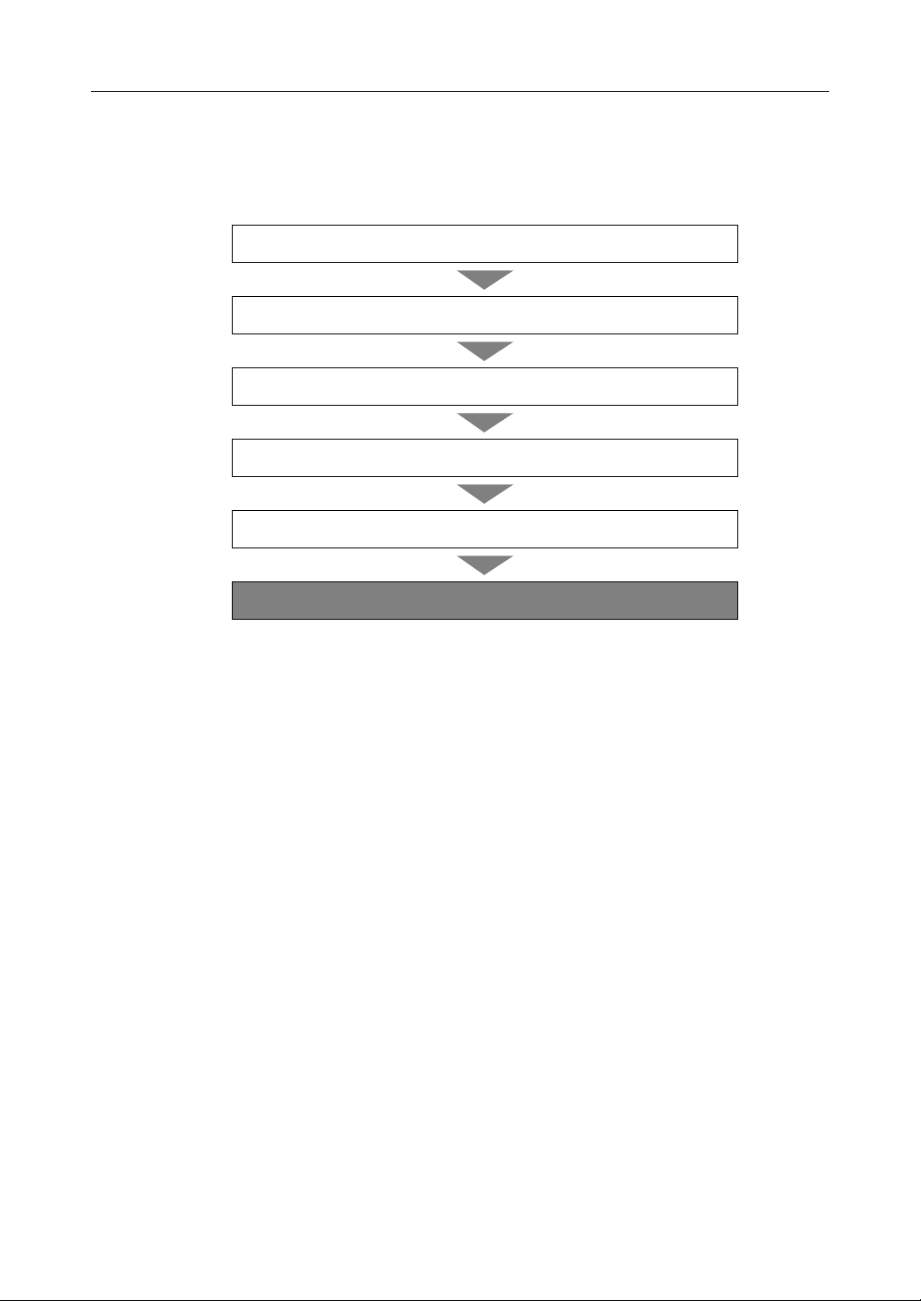
2.1 From Start to Finish
Installation/Troubleshooting
1
2
3
4
Register an ISP and Connect to the Internet
5
6
Notes
• Steps 1 to 5 are explained in this manual.
• Steps 6 is explained in Operating Instructions on the CD-ROM.
Check the Accessories
Connect This Product
Set Up the PC
Connect a Network Camera
Use This Product
7[For assistance, please call: 1-800-272-7033]
Page 8
Installation/Troubleshooting
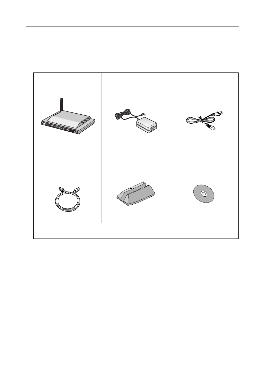
2.2 Check the Accessories
Main Unit and Included Accessories
The following items are provided with this product. Additional pieces can be ordered by calling 1-800332-5368.
Main unit ........................1 pc. AC adaptor.....................1 pc.
(Cord length: approx. 3 m (9.8
feet))
Order No. PQLV202Y
Ethernet® cable (category 5
straight cable).................1 pc.
(Cable length: approx. 1 m
(1.1 yards))
Order No. PQJA10138Z
Stand .............................1 pc.
Order No. PQYLHGW502
AC cord ......................... 1 pc.
(Cord length: approx. 1.8 m
(5.9 feet))
Order No. PSJA1069Z
CD-ROM........................ 1 pc.
(Operating Instructions etc.)
Order No. PSQX3487YCD
• Installation/Troubleshooting (this manual) - 1 pc.
• Warranty - 1 pc.
Accessories to be Provided by Customer
• Ethernet Cable (category 5 straight cable) - 1 pc.
•Network Camera
•PC
8
Page 9
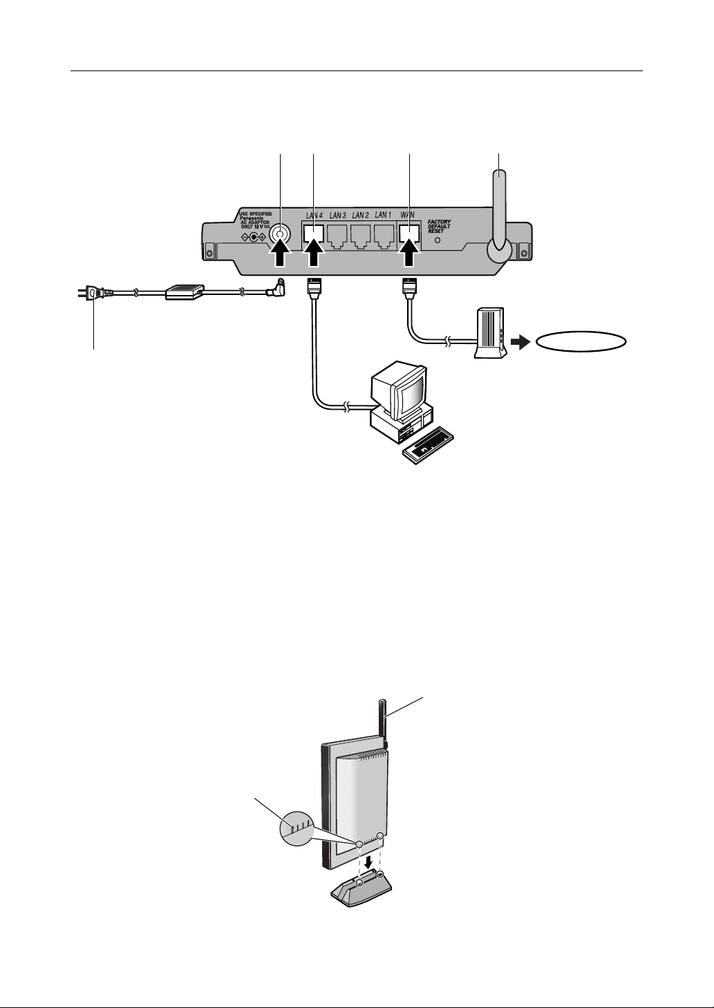
2.3 Connect This Product
To the outlet
Installation/Troubleshooting
1.2.3.4.
AC cord
(included)
5.
AC adaptor
(included)
Internet
Modem
PC
1. Raise the antenna.
2. Connect the modem to this product's WAN jack.
3. Connect the PC to this product's LAN jack.
4. Insert the AC adaptor cord into the DC IN jack of this product.
5. Insert the AC cord into the AC adaptor socket and the plug into an outlet. (This product will be
turned on automatically.)
When using the stand
Raise the antenna.
1.
Align the first groove
2.
of this product with
the stand and insert.
Adjust the antenna to
the vertical position
9[For assistance, please call: 1-800-272-7033]
Page 10
Installation/Troubleshooting
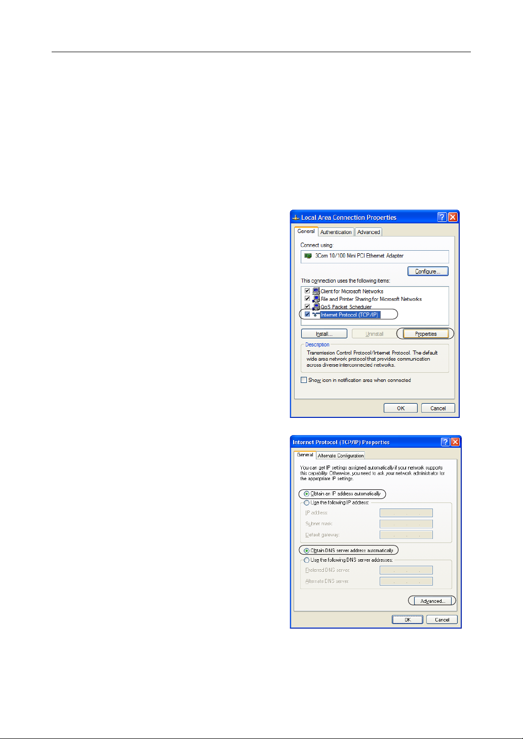
2.4 Set Up the PC
Using Windows® XP
It is necessary to log in as the administrator to change the settings on Windows XP.
1. From the Start menu, select My Computer, My
Network
connections.
2. Right-click the Local Area Connection icon and
select Properties.
3. Select Internet Protocol (TCP/IP), and click
[Properties].
Places and then View network
4. Click [Advanced...].
5. Check that the Default gateways field is empty,
and click [OK].
• If an IP address is entered in the field,
select it and click [Remove].
6. Select Obtain an IP address automatically and
also select Obtain DNS server address
automatically, and click [OK].
7. Click [Close] and close the Local Area
Connection Properties window.
10
Page 11

Installation/Troubleshooting
Using Windows 2000
It is necessary to log in as the administrator to change the settings on Windows 2000.
1. Right-click the My Network Places icon and
select Properties.
2. Right-click the Local Area Connection icon and
select Properties.
3. Select Internet Protocol (TCP/IP) and click
[Properties].
4. Click [Advanced...].
5. Check that the Default gateways field is empty
and click [OK].
• If an IP address is entered in the field,
select it and click [Remove].
6. Select Obtain an IP address automatically and
also select Obtain DNS server address
automatically, and click [OK].
7. Click [OK] and close the Local Area
Connection Properties window.
11[For assistance, please call: 1-800-272-7033]
Page 12

Installation/Troubleshooting
Using Windows Me/98SE
1. From the Start menu, select Settings and click
Control Panel.
2. Double-click the Network icon.
• If you cannot find the Network icon when
using Windows Me/98SE, click Display All
Control Panel Applications.
3. Select a TCP/IP compatible with the LAN card,
and click [Properties] in the Network dialog
box.
4. Click the IP Address tab and select Obtain an
IP address automatically.
5. Click the Gateway tab and check that the
Installed Gateway field is empty.
• If an IP address is entered in the field,
select it and click [Remove].
12
Page 13

6. Click the DNS Configuration tab, select Disable
DNS, and click [OK].
7. Click [Yes] and restart the PC.
Installation/Troubleshooting
13[For assistance, please call: 1-800-272-7033]
Page 14

Installation/Troubleshooting
2.5 Register an ISP and Connect to the Internet
1. Start up the web browser.
2. Enter "http://bbhgw.webpage:8080" into the
web browser's address bar (the default port
number is 8080)
• The user name and password window is
displayed.
3. Enter New User Name, New Password, and
Retype New Password and click [Save].
• The top page is displayed.
Notes
• It is important to always use your user name and password for authentication when using
this product.
• Access information (user name/password), this product's setup information, application
setup information, logs and other system management information is the responsibility of
the customer. Access to this information should be limited to users or user groups, and third
parties should not be allowed to refer to, modify, delete or copy this information. Information
such as user name, password, setup and management information should be kept
confidential.
.
14
Page 15

4. Click Setup.
Setup
Camera Portal
Installation/Troubleshooting
Notes
• In the default settings, it is possible to display the top page by entering "http://192.168.0.254:8080"
into the web browser's address bar.
• When accessing Setup from the top page, an authentication window is displayed (after starting the
web browser, first time only). Log in by entering your user name and password and clicking [OK].
• In order to view the camera images on the Camera Portal page of this product, it is necessary to
have completed a connection with a compatible camera (Customer-provided). See the camera's
Operating Instructions for more details.
.
If the top page is not displayed...
• Confirm that "http://bbhgw.webpage:8080" is entered correctly in the address bar (the
default port number is 8080). If the address is correct and the top page is still not displayed
enter "http://192.168.0.254:8080".
• Confirm that the LAN indicator corresponding to the jack connected to this product is on.
• Confirm that the this product's power was turned on before the PC's power was.
• Sometimes it is necessary to set up the web browser's proxy server to access the top page
(see page
122 of Operating Instructions on the CD-ROM).
15[For assistance, please call: 1-800-272-7033]
Page 16

Installation/Troubleshooting
5. Register an ISP
The ISP registration page allows you to register
new ISPs for this product, edit them, and delete
them. Internet connection methods vary according
to the ISP. Select a connection method referring to
the ISP's setup information.
Consult with your contracted ISP about which connection type to use, or about your service or contract.
Data Entry Field
Connection Type Description
PPPoE (see page 17)
• ISP Name
• User Name/Password
• Service Name
• Access Concentrator Name
• DNS Server 1/DNS Server 2
• Domain Name
DHCP (see page 19)
• ISP Name
•Device Name
•Gateway
• DNS Server 1/DNS Server 2
• Domain Name
Static (see page 21)
• ISP Name
• IP Address
• Subnet Mask
•Gateway
• DNS Server 1/DNS Server 2
• Domain Name
It is necessary to enter the following data when using
PPPoE connection. Enter the user name and
password referring to the ISP's setup information.
Enter the service name, access concentrator name
DNS server 1, DNS server 2, and/or domain name if
specified by the ISP.
When the ISP is using a DHCP server, setup entry is
not essentially necessary. However, sometimes it is
necessary to enter the device name, gateway, DNS
server 1, DNS server 2, and/or domain name. Enter
them referring to your ISP's setup information.
Enter the IP address, subnet mask, gateway, DNS
server 1, and DNS server 2 specified by the ISP. Enter
the domain name if specified by the ISP.
* If it is not necessary to enter information into the data entry field, leave it blank.
16
Page 17

PPPoE Connection
Follow the steps below to set up PPPoE connection.
ISP
Modem
Internet
The ISP assigns an IP address
by PPPoE connection.
1. Select [ISP Registration].
Installation/Troubleshooting
Private address
192.168.0.2
Private address
192.168.0.1
2. Click [Register/Edit] on the ISP registration list.
3. Select PPPoE.
17[For assistance, please call: 1-800-272-7033]
Page 18

Installation/Troubleshooting
4. Enter ISP Name.
• Enter no more than 20 characters. In the
example right, "abcde" has been entered.
5. Enter User Name and Password, and if
specified by the ISP, enter Service Name,
Access Concentrator Name, DNS Server 1, 2,
/or Domain Name.
and
• See the ISP's setup information. To return
to the original settings, click [Cancel].
6. When setup is complete, click [Save and Go to
Connection
• The connection mode page is displayed.
Mode].
7. Select the ISP entered in step 4.
8. When setup is complete, click [Save].
• The entered information is saved.
Note
When saving, do not cut the power supply. If cut, saving might not be completed successfully.
9. When [Restart] is displayed on the setup page,
click it.
10. Restart the PC.
• Check that the PC is connected to the
Internet.
Notes
• When registering or editing, restart all PCs connected to the LAN (home) side.
• When adding more PCs after setup has been completed, connect the new PCs to jacks
LAN1 to LAN4 and then restart.
• When instructed by your ISP, change the MTU value. When not instructed, leave it as the
default (1492).
18
Page 19

Installation/Troubleshooting
DHCP Connection (Internet Connection using a DHCP Server)
Follow the steps below to set up DHCP connection, where an IP address is automatically allocated by
the ISP.
ISP
Modem
Internet
The ISP's DHCP Server
assigns an IP address.
1. Select [ISP Registration].
2. Click [Register/Edit] on the ISP registration list.
3. Select DHCP.
Private address
192.168.0.2
Private address
192.168.0.1
4. Enter ISP Name.
• Enter no more than 20 characters. In the
example right, "abcde" has been entered.
5. If specified by the ISP, enter Device Name*,
Gateway, DNS Server 1, 2, and/or Domain
Name
.
• See the ISP's setup information. To return
to the original settings, click [Cancel].
* The device name is sometimes said by the
ISP to be the ID entered into the PC's
Computer Name entry field.
19[For assistance, please call: 1-800-272-7033]
Page 20

Installation/Troubleshooting
6. When setup is complete, click [Save and Go to
Connection Mode].
• The connection mode page is displayed.
7. Select the ISP entered in step 4.
8. When setup is complete, click [Save].
• The entered information is saved.
Note
When saving, do not cut the power supply. If cut, saving might not be completed successfully.
9. When [Restart] is displayed on the setup page,
click it.
10. Restart the PC.
• Check that the PC is connected to the
Internet.
Notes
• When registering or editing, restart all PCs connected to the LAN (home) side.
• When adding more PCs after setup has been completed, connect the new PCs to jacks
LAN1 to LAN4 and then restart.
20
Page 21

Installation/Troubleshooting
Static Connection (Internet Connection using a Static IP Address)
It may be necessary, if you are instructed by the ISP, to enter the value of the IP address or gateway
address into setup information.
Private address
ISP
Modem
Internet
Static IP Address
An IP address is set based
on information from the ISP.
192.168.0.2
Private address
192.168.0.1
1. Select [ISP Registration].
2. Click [Register/Edit] on the ISP registration list.
3. Select Static.
21[For assistance, please call: 1-800-272-7033]
Page 22

Installation/Troubleshooting
4. Enter ISP Name.
• Enter no more than 20 characters. In the
example right, "abcde" has been entered.
5. Enter the IP Address, Subnet Mask, Gateway
and DNS server 1, 2, and if specified by the
ISP, enter the Domain Name.
• See the ISP's setup information. To return
to the original settings, click [Cancel].
6. When setup is complete, click [Save and Go to
Connection
• The connection mode page is displayed.
Mode].
7. Select the ISP entered in step 4.
8. When setup is complete, click [Save].
• The entered information is saved.
Note
When saving, do not cut the power supply. If cut, saving might not be completed successfully.
9. When [Restart] is displayed on the setup page,
click it.
10. Restart the PC.
• Check that the PC is connected to the
Internet.
Notes
• When registering or editing, restart all PCs connected to the LAN (home) side.
• When adding more PCs after setup has been completed, connect the new PCs to jacks
LAN1 to LAN4 and then restart.
22
Page 23

2.6 Connect a Network Camera
To the modem
To the PC
To the outlet
Installation/Troubleshooting
2.
1.
3.
1. Connect the Ethernet cable between the camera and the LAN jack of the router.
2. Insert the AC adaptor cord into the DC IN jack of the camera.
3. Insert the AC cord into the AC adaptor socket and the plug into an outlet (The camera will be
turned on automatically.)
Camera Automatic Setup
If a Panasonic Network Camera (Customer-provided) is connected and the power turned on, this
product automatically sets the IP address, subnet mask and other network settings. After this
product is connected to the Internet, check that the camera is turned off and follow the steps
above.
23[For assistance, please call: 1-800-272-7033]
Page 24

Installation/Troubleshooting
.
4. Check the connection.
1) To display the top page of this product start
up the web browser, enter "http://
bbhgw.webpage:8080" into the address
bar, and press [Enter].
• In standard settings, if you enter "http:/
/192.168.0.254:8080" into the web
browser's address bar, the top page will
be displayed.
2) Check that the camera indicator is shining
green and click [Camera Portal].
3) Click a camera frame on the camera portal
page, access the camera, and check that it
is connected.
• If a single camera page is displayed,
setup is completed.
• If an exclamation mark is displayed,
click it and the camera's password
window is displayed. Perform the
settings on each page. Setting Allow
Access from the Internet to Enable,
displays the camera images on the
Camera Portal over the Internet. Setting
Disable only displays the camera
images on the Camera Portal when
accessing from the LAN side.
(It is displayed when a factory default
camera is connected.)
1) Enter "http://bbhgw.webpage:8080"
2) Click here.
3) Click here.
24
• If a key mark is displayed, click it and
enter that camera's user name and
password.
(If camera authentication has been set
up, the key mark will be displayed.)
Page 25

Installation/Troubleshooting
• A blue unmarked window is displayed
when the camera is outside operation
time. If a blue unmarked window is
displayed even when the camera is
operating, click [Refresh Camera].
(A blue unmarked window may be
displayed when authentication is being
confirmed.)
• If the camera and this product are
disconnected while sending or
receiving data, a key mark (when
camera authentication is set up) or a
blue unmarked window is displayed. In
this case, after checking that the
camera's power supply and
connections are correctly inserted, click
[Refresh Camera].
5. Install the camera
• See the Operating Instructions of each camera for details of how to install the camera.
• When using a wireless camera, remove the AC adaptor from the outlet, remove the Ethernet
cable, and install the camera in the wireless mode.
• See page 39 in Operating Instructions on the CD-ROM for details of the automatic camera
setup function.
25[For assistance, please call: 1-800-272-7033]
Page 26

Installation/Troubleshooting
3 Troubleshooting
Up-to-date support information can be found on the Panasonic Support Website (http://
panasonic.co.jp/pcc/products/en/netwkcam/). Please refer to it, along with this guide, when
troubleshooting.
Checking Connection
Problem Cause and Remedy
The modem is
connected but the WAN
indicator is off.
The Ethernet is
connected but the LAN1
- LAN4 indicators are
off.
• Check that the modem and this product are connected.
• Check that the power of the modem and this product are turned
• Check the connection of the PC etc.
• Check that the power of the PC etc. is turned on.
• Check that the LAN card and driver are installed on the PC.
Internet Website Display
Problem Cause and Remedy
A website is not
displayed.
• Check that the website address was correctly entered in the web
• Check the connection of the modem. Also check the connection
• Check the information received from the ISP regarding Internet
• When instructed to do so by the ISP, set the web browser proxy
• If the power is cut when connected to the Internet using PPPoE,
• Check that the power supply was turned on in the following order:
on.
browser's address bar.
between this product and the LAN.
connection. If it is necessary to enter settings information, see
ISP Registration (see page
CD-ROM).
server (see page 122 of Operating Instructions on the CD-ROM).
it may take between 5 and 20 minutes to reconnect to the
Internet.
modem, this product, PC.
21 of Operating Instructions on the
26
Page 27

Setup Pages Display
Problem Cause and Remedy
Installation/Troubleshooting
The Top Page or Setup
Page is not displayed.
• Dialog boxes may not be displayed immediately due to the state
of the LAN.
• Check that one of LAN1 - LAN4 or WIRELESS indicators are
shining green. Also, check if the LAN card or wireless LAN card
is on. If not, check that the LAN is connected.
• Check that the power supply was turned on in the following order:
modem, this product, PC connected to the LAN side.
• Check that an IP address has been assigned to the LAN side PC
by this product (see page 123 of Operating Instructions on the
CD-ROM). If it has not been assigned, check that the PC has
been set to Obtain IP Address Automatically, and restart the PC.
• If this product's IP address has been modified (see page 74 of
Operating Instructions on the CD-ROM), enter the new IP
address in the web browser's address bar. (The default port
number is 8080.)
• To access the setup page, it may be necessary to set the web
browser. (see page 122 of Operating Instructions on the CDROM)
• JavaScript is used on the setup page. If JavaScript is disabled in
the web browser settings, enable it and then access the setup
page.
1 Select Internet Explorer Tools, then Internet Options... in
Internet Explorer, and click the Security tab.
2 Click Custom Level... in Security level for this zone.
3 Enable "Active scripting" in Settings.
27[For assistance, please call: 1-800-272-7033]
Page 28

Installation/Troubleshooting
Problem Cause and Remedy
The Camera Portal or
Setup Page is not
displayed.
The Update Firmware
page is displayed.
• Check that one of LAN1 - LAN4 or WIRELESS indicators are
shining green. Also, check if the LAN card or wireless LAN card
is on. If not, check that the LAN is connected.
• Check that an IP address has been assigned to the LAN side PC
by this product (see page 123 of Operating Instructions on the
CD-ROM). If it has not been assigned, check that the PC has
been set to Obtain IP Address Automatically, and restart the PC.
• If this product's IP address (:port number)has been modified (see
74 of Operating Instructions on the CD-ROM), enter the
page
new IP address (:port number) in the web browser's address bar.
(The default port number is 80. When the port number is 80 it is
not necessary to enter it.)
• Access the Camera Portal 1 minute after turning on the power. If
accessed before 1 minute has passed, The page cannot be
displayed message is displayed.
• To access the setup page, it may be necessary to set the web
browser. (see page
ROM)
• JavaScript is used on the setup page. If JavaScript is disabled in
the web browser settings, enable it and then access the setup
page.
1 Select Internet Explorer Tools, then Internet Options... in
Internet Explorer, and click the Security tab.
2 Click Custom Level... in Security level for this zone.
3 Enable "Active scripting" in Settings.
• The firmware is damaged. Re-install the firmware. (see page 95
of Operating Instructions on the CD-ROM)
122 of Operating Instructions on the CD-
The wireless device
cannot be connected.
28
• Change the PC wireless LAN card's communication mode to
Infrastructure. The device-specific SSID and 128-bit encryption
key are set in factory default. The default SSID and 128 bit
encryption key are displayed on the rear of this product. Set the
same SSID and 128-bit encryption key as those on the wireless
devices connected to this product.
• It is possible that this product or the wireless device may be out
of range, or there is a wall or other obstacle in between them.
Move them closer together.
Page 29

Camera Setup
Problem Cause and Remedy
Installation/Troubleshooting
The camera is not
automatically
registered on the
Camera Portal page.
When accessing the
Camera Portal, an
authentication window
is displayed.
The camera cannot be
registered manually.
• Check that this product, the camera and the PC are all
connected.
• If the camera's FACTORY DEFAULT RESET button is pressed
while this product is starting up (the first 30 seconds after turning
on the power), the camera may not be registered automatically.
In this case, press the camera's FACTORY DEFAULT RESET
button again after this product has started up.
• Automatic registration cannot be performed if the Enable check
box in Network Configuration from Setup Program in Network on
the camera setup page, has not been checked. Ensure that it is
checked.
• An IP address (192.168.0.151 - 192.168.0.166) is used for
automatic camera registration. Check that the IP address is not
the same as an IP address for any of the other network devices.
The same IP address cannot be used.
• Administrator Only was set for the Camera Portal by accessing
Access Control in Security in Advanced Setup. Enter the set user
name and password.
• The IP addresses (192.168.0.151 - 192.168.0.166), and port
numbers (53, 80[portal page], 1723, 8080[setup page], 10000,
60001 - 60016), are used by this product. The same IP address
or port number cannot be used.
• When manually registering a camera, it is necessary to register
the camera in Automatic Setup in Camera, arrange the camera
on the portal in Screen Assignment, and register the camera in
Address Translation.
29[For assistance, please call: 1-800-272-7033]
Page 30

Installation/Troubleshooting
Problem Cause and Remedy
The Camera Portal or
Setup Page cannot be
accessed from the WAN
side.
Wireless Setup
• The network may be congested. Wait a while and try to connect
again.
• To access the setup page, it may be necessary to set the web
browser. (see page 122 of Operating Instructions on the CDROM)
• JavaScript is used on the setup page. If JavaScript is disabled in
the web browser settings, enable it and then access the setup
page.
1 Select Internet Explorer Tools, then Internet Options... in
Internet Explorer, and click the Security tab.
2 Click Custom Level... in Security level for this zone.
3 Enable "Active scripting" in Settings.
• The Camera Portal section of Access Control in Security in
Advanced Setup is set to Restricted Access on this product. Set
it to None or Administrator Only.
• Access may be prohibited in Security on the setup page. See
Filtering Log in Log on the setup page and make it accessible.
• When connecting this product under another router, use a router
that is compatible with UPnP™. This product cannot be used
when connected using a router with an in-built modem without
the UPnP™ function. Set the CP function to Enable referring to
80 of Operating Instructions on the CD-ROM.
page
• Viewnetcam.com may not be registered. Register to
Viewnetcam.com using the Link for Viewnetcam.com Service.
Problem Cause and Remedy
After setting MAC
Address Filtering,
wireless connection
does not work.
Others
Problem Cause and Remedy
The POWER indicator is
blinking red.
30
• See the Panasonic Support Website (http://panasonic.co.jp/pcc/
products/en/netwkcam/) for more details about setup.
• The hardware is damaged. Remove the AC cord plug from the
outlet and re-insert it (see page
contact an authorized servicenter.
9). If the problem is not solved,
Page 31

Problem Cause and Remedy
Installation/Troubleshooting
The POWER indicator is
blinking green.
"The system has
detected a conflict for
IP address with the
system having
hardware address
XX:XX:XX:XX:XX:XX"
or "Another device on
your TCP/IP Internet,
which has the physical
address
XX:XX:XX:XX:XX:XX, is
currently using the
same IP address
(XXX.XXX.XXX.XXX).
Your TCP/IP network
interface has been shut
down." is displayed in
the dialog box.
• The firmware is damaged. Take the following steps to update the
firmware. (Connect this product and the PC using a wire
connection. Firmware cannot be updated on a wireless
connection.)
When blinking quickly: 0.4 second intervals
1 Cut the power to this product.
2 Turn on the power while holding the FACTORY DEFAULT
RESET button on the rear of this product.
(see page 109 of Operating Instructions on the CD-ROM for
the location of the button)
3 After about 5 seconds when the POWER indicator has turned
off, release the FACTORY DEFAULT RESET button.
The POWER indicator should blink green again.
4 Enter "http://192.168.0.254:8080" into the web browser's
address bar (http://bbhgw.webpage cannot be used).
5 Update when the update firmware window is displayed (see
95 of Operating Instructions on the CD-ROM)
page
When blinking slowly: 1 second intervals
1 Enter "http://192.168.0.254:8080" into the web browser's
address bar (http://bbhgw.webpage cannot be used).
2 Update when the update firmware window is displayed (see
page 95 of Operating Instructions on the CD-ROM).
• Turn off all the devices. Turn on this product and then the PC.
• Check that all the PCs are set to Obtain IP Address
Automatically.
• Check that the available address range and each of the IP
addresses of the specific devices in the network do not overlap.
After clicking [Restart]
on the setup page, the
basic setup page is not
displayed.
The password to
access the setup page
has been forgotten.
• Click the web browser's refresh button.
• After restarting the PC, access the setup page again.
• Push the FACTORY DEFAULT RESET button, and initialize this
product (see page 109 of Operating Instructions on the CD-ROM
for the location of the button). The settings are returned to factory
default. Reset the user name and password.
31[For assistance, please call: 1-800-272-7033]
Page 32

For product service
Panasonic Servicenters are listed in the servicenter directory.
Call 1-800-272-7033 for the location of an authorized servicenter.
This product is designed for use in the United States of America. Sale or use of this product
in other countries/areas may violate local laws.
When you ship the product
Carefully pack your unit, preferably in the original carton.
Attach a letter, detailing the problem, to the outside of the carton.
Symptom
Send the unit to an authorized servicenter, prepaid and adequately insured.
Do not send your unit to the Panasonic Consumer Electronics Company listed below or to executive
or regional sales offices. These locations do not repair consumer products.
The information in this document is subject to change without notice.
Panasonic Consumer Electronics Company,
Division of Panasonic Corporation of North America
Panasonic Puerto Rico, Inc.
Copyright:
This material is copyrighted by Panasonic Communications Co., Ltd., and may be reproduced for
internal use only. All other reproduction, in whole or in part, is prohibited without the written
consent of Panasonic Communications Co., Ltd.
2004 Panasonic Communications Co., Ltd. All Rights Reserved.
Printed in Japan
PSQX3486YA KK1104GJ1025
 Loading...