

Panasonic AW-HE100E Operating Instructions Manual
Installation Instructions provided separately
РУССКИЙ
FRANÇAIS DEUTSCH ENGLISH
ITALIANO
ESPAÑOL
Before operating this product, please read the instructions carefully and save this manual for future use.
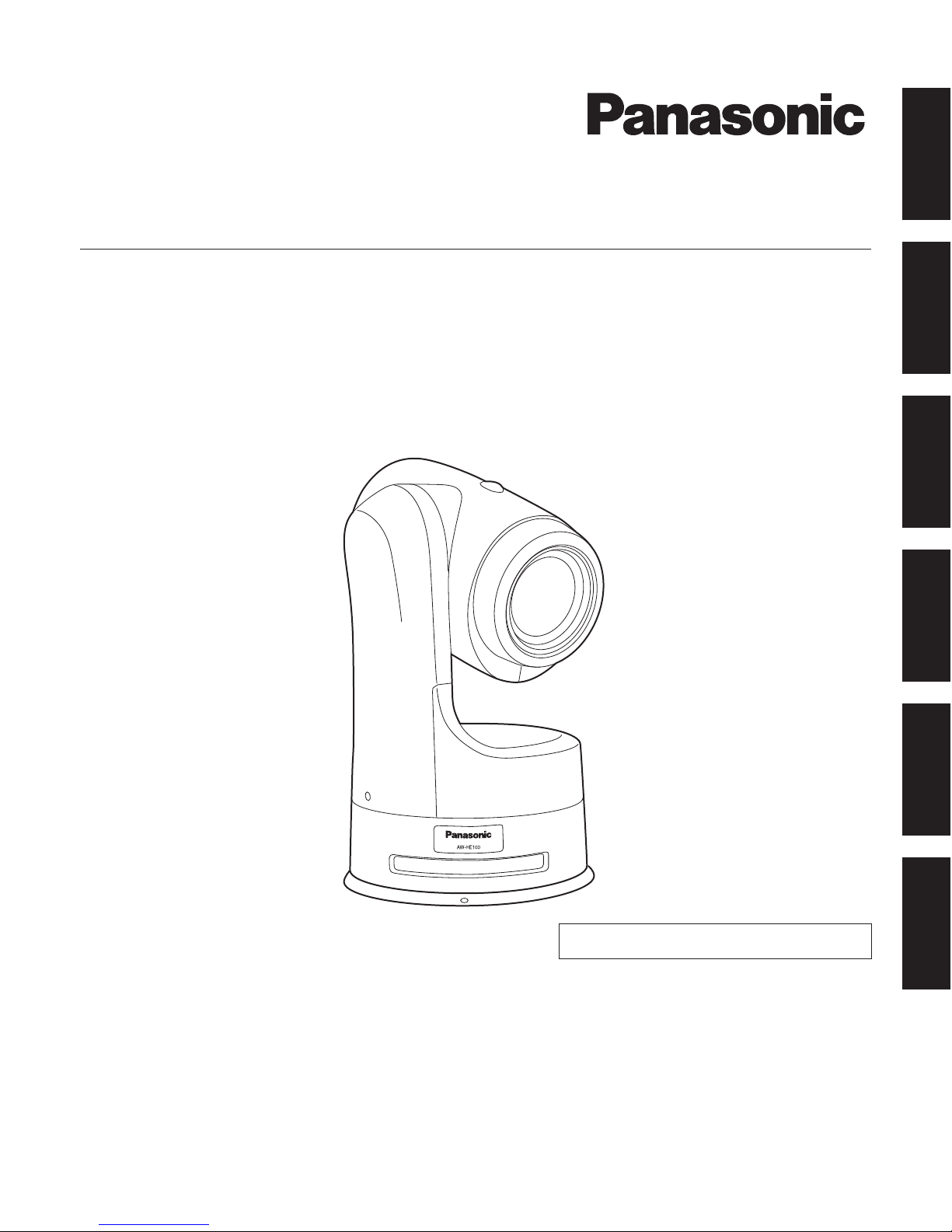
Operating Instructions
HD Integrated Camera
Model No. AW-HE100E
VQTB0332
1 (E)
indicates safety information.
Safety precautions
WARNING:
THIS APPARATUS MUST BE EARTHED
To ensure safe operation, the three-pin plug must
be inserted only into a standard three-pin power
point which is effectively earthed through the normal
household wiring.
Extension cords used with the apparatus must
have three cores and be correctly wired to provide
connection to the earth. Wrongly wired extension
cords are a major cause of fatalities.
The fact that the apparatus operates satisfactorily
does not imply that the power point is earthed or that
the installation is completely safe. For your safety, if
you are in any doubt about the effective earthing of
the power point, please consult a qualified electrician.
The socket outlet shall be installed near the
equipment and easily accessible or the mains plug or
an appliance coupler shall remain readily operable.
A warning that an apparatus with CLASS I
construction shall be connected to a MAINS socket
outlet with a protective earthing connection.
ENGLISH VERSION
DO NOT REMOVE PANEL COVERS BY
UNSCREWING.
To reduce the risk of electric shock, do not remove
the covers. No user serviceable parts inside.
Refer servicing to qualified service personnel.
WARNING:
• TO REDUCE THE RISK OF FIRE OR ELECTRIC
SHOCK, DO NOT EXPOSE THIS APPARATUS TO
RAIN OR MOISTURE.
• THE APPARATUS SHALL NOT BE EXPOSED
TO DRIPPING OR SPLASHING AND THAT NO
OBJE CTS FILL ED WI TH L IQUI DS, SU CH
AS VASES , SHAL L B E P LACED ON T HE
APPARATUS.
CAUTION:
TO REDUCE THE RISK OF FIRE OR SHOCK
HAZARD AND ANNOYING INTERFERENCE, USE
THE RECOMMENDED ACCESSORIES ONLY.
WARNING:
TO PREVENT INJURY, THIS APPARATUS
MUST BE SECURELY ATTACHED TO THE
FLOOR/WALL IN ACCORDANCE WITH THE
INSTALLATION INSTRUCTIONS.
CAUTION:
In order to maintain adequate ventilation, do not
install or place this unit in a bookcase, built-in
cabinet or any other confined space. To prevent
risk of electric shock or fire hazard due to
overheating, ensure that curtains and any other
materials do not obstruct the ventilation.
Information on Disposal for Users of Waste Electrical & Electronic Equipment (private households)
This symbol on the products and/or accompanying documents means that used electrical and electronic
products should not be mixed with general household waste.
For proper treatment, recovery and recycling, please take these products to designated collection points,
where they will be accepted on a free of charge basis. Alternatively, in some countries you may be able to
return your products to your local retailer upon the purchase of an equivalent new product.
Disposing of this product correctly will help to save valuable resources and prevent any potential negative
effects on human health and the environment which could otherwise arise from inappropriate waste handling.
Please contact your local authority for further details of your nearest designated collection point.
Penalties may be applicable for incorrect disposal of this waste, in accordance with national legislation.
For business users in the European Union
If you wish to discard electrical and electronic equipment, please contact your dealer or supplier for further information.
Information on Disposal in other Countries outside the European Union
This symbol is only valid in the European Union.
If you wish to discard this product, please contact your local authorities or dealer and ask for the correct method of disposal.
2 (E)
ENGLISH
Safety precautions
indicates safety information.
Caution for AC Mains Lead
FOR YOUR SAFETY PLEASE READ THE FOLLOWING TEXT CAREFULLY.
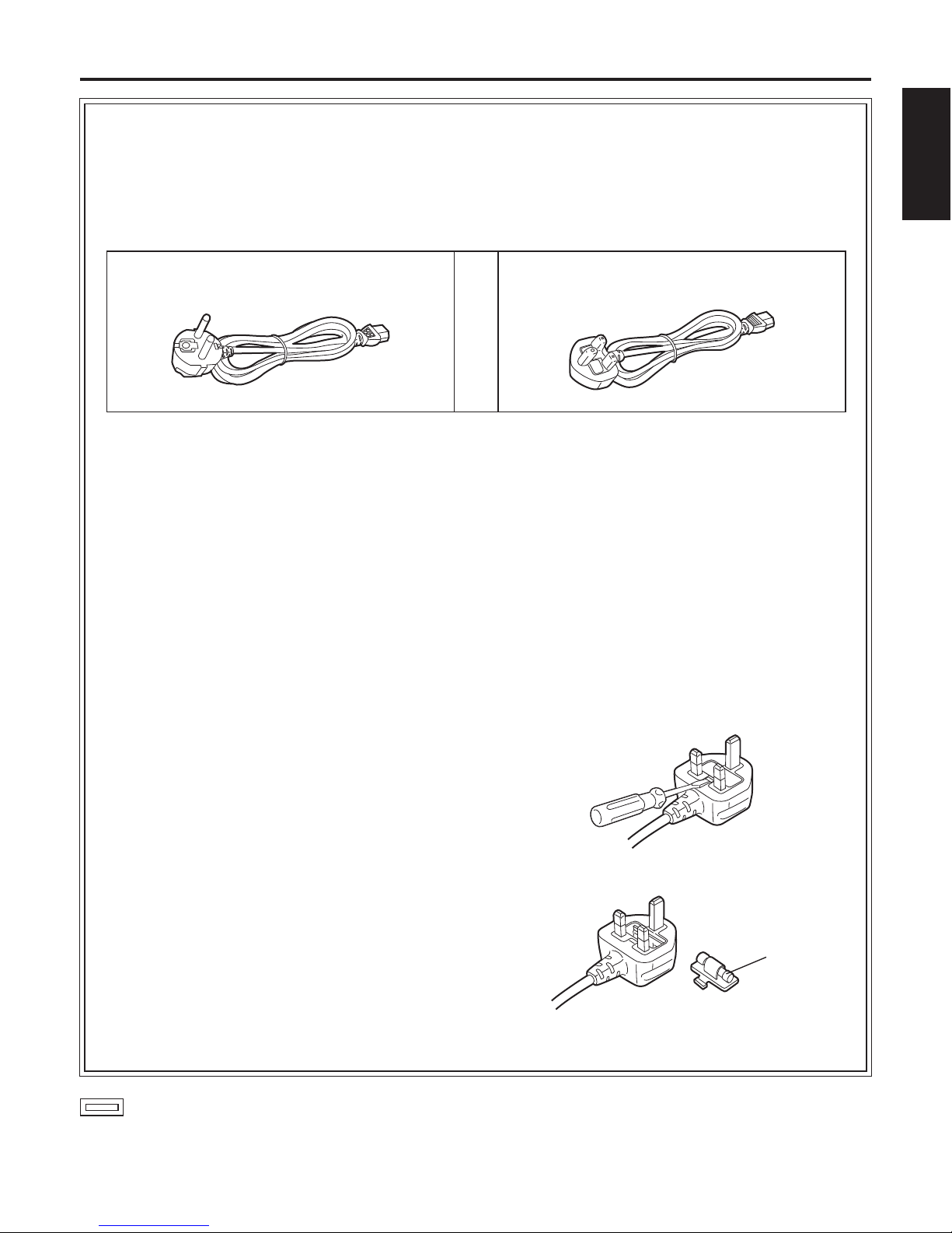
This product is equipped with 2 types of AC mains cable. One is for continental Europe, etc. and the other one is only
for U.K.
Appropriate mains cable must be used in each local area, since the other type of mains cable is not suitable.
FOR CONTINENTAL EUROPE, ETC.
Not to be used in the U.K.
FOR U.K. ONLY
FOR U.K. ONLY
This appliance is supplied with a moulded three pin
mains plug for your safety and convenience.
A 13 amp fuse is fitted in this plug.
Should the fuse need to be replaced please ensure that
the replacement fuse has a rating of 13 amps and that it
is approved by ASTA or BSI to BS1362.
Check for the ASTA mark or the BSI mark on the
body of the fuse.
If the plug contains a removable fuse cover you must
ensure that it is refitted when the fuse is replaced.
If you lose the fuse cover the plug must not be used until
a replacement cover is obtained.
A replacement fuse cover can be purchased from your
local Panasonic Dealer.
IF THE FITTED MOULDED PLUG IS UNSUITABLE
FOR THE SOCKET OUTLET IN YOUR HOME THEN
THE FUSE SHOULD BE REMOVED AND THE PLUG
CUT OFF AND DISPOSED OF SAFELY.
THERE IS A DANGER OF SEVERE ELECTRICAL
SHOCK IF THE CUT OFF PLUG IS INSERTED INTO
ANY 13 AMP SOCKET.
If a new plug is to be fitted please observe the wiring
code as shown below.
If in any doubt please consult a qualified electrician.
WARNING: This apparatus must be earthed.
IMPORTANT
The wires in this mains lead are coloured in accordance
with the following code.
Green-and-Yellow: Earth
Blue: Neutral
Brown: Live
As the colours of the wire in the mains lead of this
appliance may not correspond with the coloured
markings identifying the terminals in your plug, proceed
as follows.
• The wire which is coloured
green-and-yellow must be
connected to the terminal in the plug which is marked
with the letter E or by the earth symbol or coloured
green or green-and-yellow.
• The wire which is coloured
blue must be connected to
the terminal in the plug which is marked with the letter
N or coloured black.
• The wire which is coloured
brown must be connected
to the terminal in the plug which is marked with the
letter L or coloured red.
How to replace the fuse
1. Open the fuse compartment with a screwdriver.
2. Replace the fuse.
Fuse

3 (E)
Contents
Safety precautions ...................................................1
Accessories ..............................................................4
Overview .................................................................... 4
Characteristics .......................................................... 5
Installation precautions ........................................... 6
Operating precautions ............................................. 7
Concerning the controller ........................................ 8
Parts and their functions ......................................... 9
Concerning the wireless remote control .............. 13
Getting the wireless remote control ready ........... 13
Basic shooting operations ....................................14
How to turn the power on and off ......................... 15
Selecting the units .................................................. 17
Selecting the shooting modes (scene files) ......... 18
Shooting .................................................................. 21
What to do when encountering problems
in the basic shooting operations ....................... 22
More advanced operations .................................... 23
Manual shooting ..................................................... 24
Preset memories ..................................................... 28
White balance adjustment ..................................... 30
Black balance adjustment .....................................33
Black level (total pedestal) adjustment ................ 34
Genlock adjustment ............................................... 36
Basic menu operations .......................................... 39
Setting the menu items .......................................... 42
Menu item table ......................................................51
Limiters .................................................................... 52
Setting/releasing the limiters ................................53
Safe modes .............................................................54
Troubleshooting ...................................................... 55
Maintenance ............................................................ 57
Replacing the consumable parts .......................... 57
Appearance ............................................................. 58
Specifications ......................................................... 59
Caution
The manual of this HD integrated camera (hereafter, “the unit”) is divided into two manuals: one is the Operating
Instructions (this manual), and the other is the Installation Instructions.
Before installing the unit, be sure to read the Installation Instructions to ensure that the unit is installed correctly.
For the purposes of this manual, the model number AW-HE100E is referred to as the “AW-HE100”.
Similarly, the model number AW-RP655L is referred as the “AW-RP655”, the AW-RP555L as the “AW-RP555”, the
AW-RP400L as the “AW-RP400”, the AW-IF400G as the “AW-IF400” and the AW-CB400L as the “AW-CB400”.

4 (E)
ENGLISH
Accessories
Check that the following accessories are present and accounted for.
Installation Instructions ....................................................... 1
Operating Instructions (CD-ROM) ...................................... 1
Wireless remote control ...................................................... 1
This uses two size “R6” or “LR6” dry batteries.
(obtained separately)
Power cables
(2 m, for UK, for other country) ......................... 1 pc each
Installation surface bracket (for floor or ceiling) .................. 1
Cable cover ..........................................................................1
Mounting screws (with flat washers, spring washers)
M4 8 mm .....................................................................4
Cable cover screws (flat head)
M3 6 mm .....................................................................2
Screw concealment sheet ....................................................2
Rubber feet ...........................................................................4
Rubber foot screws (black)
M4 6 mm .....................................................................4
Filter ......................................................................................1
Clampers ..............................................................................2
Overview
This unit is a multi-format camera that integrates a pan-tilt head and a zoom lens.
By integrating the camera, lens and pan-tilt head, it has now become easier to install the unit than before.
The unit can also be operated by remote control using the wireless remote control provided as an accessory.

5 (E)
Characteristics
Multiple number of formats supported
Switching between the 1080i, 720p and 576i formats can be accomplished using a menu.
Transition from an SD format system to an HD format system can also be carried out smoothly.
With the SD format, either 16:9 or 4:3 can be selected as the aspect ratio.
Three 1/3˝ CCD imaging sensors and a high-performance 13 zoom lens featured
The unit incorporates a 14-bit analogue-to-digital (A/D) converter and a 19-bit processing DSP (digital signal processor).
High-quality pictures are obtained by video processing in many different kinds of ways.
The unit comes with wide progressive CCD imaging sensors which have been newly developed.
These 1/3˝ CCD sensors have a large light-sensing surface area so that pictures with a high quality can be obtained under
a variety of different shooting conditions.
The large-diameter lens that was developed for shooting HD pictures has a wide angle of 32.5 mm (35 mm equivalent) at the
WIDE setting. Clear pictures are obtained under a wide range of applications.
Easy operation of unit enabled by its integration with a high-performance pan-tilt head unit
Operations at the high speed of 60°/s
Wide rotational angles with a panning range of more than ±175° and a tilting range from –40° to +210° or more
Standstill accuracy: Accurate response of max. 3´ (0.05°)
Quiet operation with noise levels of NC30 (for operations at 30°/s) and NC35 (for operations at 60°/s)
Storage of up to 100 positions in the preset memory
(The number of preset memory settings differs depending on the controller that is used with the unit.)
High degree of compatibility with Panasonic’s currently available controllers, enabling a flexible system to be put
together
Up to five units and devices can be operated using a controller (AW-RP655, AW-RP555 or AW-RP400 + AW-IF400 +
AW-CB400) currently available from Panasonic. (It may be necessary to upgrade the version of the controller in order to
support the unit. The maximum distances between the units and controller is 1000 meters. Use of an external device or some
other means must be provided separately in order to extend the video signal connections.)
The unit can also be used together with the cameras and pan-tilt head unit systems currently available from Panasonic so
that an existing system can be used to advantage to put together a system that is even more flexible.
Integrated pan-tilt head unit, camera and lens to facilitate installation
Integrating the pan-tilt head unit, camera and lens has significantly reduced the processes involving in installation.
Easy-to-operate wireless remote control provided as a standard accessory
A wireless remote control capable of operating up to four units is provided as a standard accessory.
It can easily be used to set the various functions or switch between them while viewing the menu screens.

6 (E)
ENGLISH
Installation precautions
In addition to heeding the points presented in the “Safety precautions”, observe the following
precautions as well.
Concerning the installation location
After conferring in detail with your dealer, choose a sturdy
ceiling or other surface, and install the unit.
Install the unit on a ceiling that is strong enough (such as
a concrete ceiling).
If the unit is to be installed on a ceiling which is not strong
enough, reinforce the ceiling sufficiently first.
Do not install or use the unit in the following kinds of
locations.
On walls (where the unit would be installed sideways)
In locations (including places such as under the eaves of
a building) where the unit would be directly exposed to
rain or water
In locations such as kitchens where there are high
concentrations of steam and grease
In outdoor locations or hot places where the temperature
will exceed 40 °C
In cold locations where the temperature will drop below
0 °C
In locations where the humidity will exceed 85 %
In locations where chemicals are used such as near
swimming pools
At sea, in coastal areas or in locations where corrosive
gases are emitted
In locations where the unit would be subject to a great
deal of vibration such as on board a vehicle or ship (this
unit is not designed to be used in vehicles)
In locations where the temperature is subject to sudden
changes such as near the air outlet of an air conditioner
or near a door which allows the outside air to come in
What to avoid to ensure that the unit will perform stably
over a prolonged period
Using the unit for a prolonged period in a location with
high temperature and humidity levels will cause its parts
to deteriorate and shorten its service life.
Do not expose the unit directly to the heat given off in the
installation location or heat from a heater or other such
appliance.
The accessory parts provided with the unit must be
used without fail to install the unit.
Be absolutely sure to use the mounting brackets and
mounting screws provided with the unit to install the unit.
Separately obtain the screws used to mount the
installation surface bracket.
This unit does not come with the screws used to mount the
installation surface bracket.
Obtain the hexagon head bolts (M6), spring washers, flat
washers and, if necessary, nuts.
Tightening the installation screws
Tighten up the screws and bolts to an extent that is
commensurate with the materials and structures in the
installation location.
After tightening up the screws and bolts, visually inspect
for any ricketiness or play, and check that the unit is
secured properly in place.
Use the specified tools and tighten the screws firmly.
When the unit is no longer going to be used, do not
leave it lying around, but be absolutely sure to dispose
of it properly.
When installing or disposing of the unit, be absolutely
sure to hold it by its pedestal area.
An accident may occur if its rotating part is held or rotated
by hand.
Do not attach a filter, hood, extender or other parts to
the unit.
Be absolutely sure to use size “R6” or “LR6” dry
batteries for the wireless remote control.
Do not use any other kind of batteries.
Install the unit near the main power outlet, and position
it in such a way that its power plug can be plugged into
and unplugged from the outlet easily.
Do not connect a regular LAN line or telephone line to
the CONTROLLER connector on the unit.
Doing so may cause malfunctioning.

7 (E)
Operating precautions
Shoot under the proper lighting conditions.
To produce pictures with eye-pleasing colours, shoot
under the proper lighting conditions.
The pictures may not appear with their proper colours
when shooting under fluorescent lights. Select the proper
lighting as required.
What happens with high-brightness subjects
Shooting very bright objects may give rise to the smear
effect, which is a phenomenon inherent to CCD cameras.
Smear: This is a type of distortion characterized by
bright vertical stripes appearing on very bright
or shiny subjects, which include light bulbs or
incandescent lamps.
When using the automatic functions
When using the ATW (auto tracking white adjustment)
function under fluorescent lights, the white balance may
vary.
In some situations, it may be hard to focus at the auto
setting. In cases like this, select the manual setting, and
focus manually.
The appropriate brightness may not be obtained when
shooting bright objects using the auto settings for the
gain and iris. In cases like this, set the shutter speed to
manual, and adjust.
Zooming and focusing
When the focus is set to manual, the subject may go out
of focus during zooming. Therefore, the unit comes with a
function which compensates for this. (Focus compensation
during zooming function)
This function was set to ON at the factory.
If the function has been set to OFF, either adjust the focus,
as required, after zooming or set the focus to auto.
Aspect ratio of the composite video signals
When 1080i or 720p has been selected as the video
format, the aspect ratio of the composite video signals is
fixed at 16:9 (squeeze).
Concerning the zoom position when the power is turned
on
When the unit’s power is turned on, the zoom, focus and iris
return to the positions they occupied immediately before the
power was turned off. (This happens for the focus and iris
when they were set manually.)
However, this position may not be restored if, for instance,
the power cable was disconnected during operation.
Do not approach the moving parts!
Under no circumstances should you bring your fingers or
other parts of your body near the moving parts since doing
so may result in injury.
The unit comes with safe modes.
The safe modes are functions designed to protect people
and property from injury and the pan-tilt head unit from
damage.
For further details, refer to “Safe modes” (page 54).
Turn off the power before connecting or disconnecting
the cables.
Always be sure to turn off the power before connecting or
disconnecting the cables.
Handle the unit carefully.
Do not drop the unit or subject it to strong impact or
vibration. Doing so may cause the unit to malfunction.
When the unit is not in use
Turn off the unit’s power when it is not in use. When the
unit is no longer going to be used, do not leave it lying
around, but be absolutely sure to dispose of it properly.
Do not touch the optical system parts.
The optical system parts are the very heart of the
camera. Under no circumstances must they be touched.
In the unlikely event that they have become dusty, remove
the dust by using a camera blower or by wiping them
gently with a lens cleaning paper.
Refrain from attaching a filter, hood, extender or other
parts to the unit.
Do not mount a filter, hood, extender or other parts on the
unit.
Hold the pedestal when carrying the unit around.
Do not hold the unit by its camera part or pan-tilt head.
Doing so may cause the unit to malfunction.
Do not turn the rotating parts by hand.
Turning the rotating parts by hand may cause the unit to
malfunction.
Use the unit in an environment with minimal moisture
and dust.
Avoid using the unit in an environment with high
concentration of moisture or dust since these conditions
will damage the internal parts.
Operating temperature range
Avoid using the unit in cold locations where the
temperature drops below 0 °C or hot locations where
the temperature rises above +40 °C since these
temperatures downgrade the picture quality and
adversely affect the internal parts.
Disposal of the unit
When the unit has reached the end of its service life and
is to be disposed of, ask a qualified contractor to dispose
of the unit properly in order to protect the environment.

8 (E)
ENGLISH
Concerning the controller
Controller supported
AW-RP655 AW-RP555
AW-RP400 + AW-IF400 + AW-CB400 (System which combines the AW-RP400, AW-IF400 and AW-CB400)
It may be necessary to upgrade the version of the controller in order to support the unit.
Consult with your dealer.
When connecting the AW-RP655
The camera setting menus of the AW-RP655 cannot be used.
Use the camera setting menus of the unit instead.
When connecting the AW-RP400 + AW-IF400 + AW-CB400
The AW-CB400 cannot be connected directly to this unit.
The AW-CB400 must be connected together with the AW-RP400 and AW-IF400 in combination.
The camera setting menus of the AW-CB400 cannot be used.
Use the camera setting menus of the unit instead.
R/B PED dials cannot be used.
The tracing memory function cannot be used.
TILT RANGE cannot be set.
MEMORY LENGTH cannot be set.
DIAGONAL MOTION cannot be set to ON or OFF.
Backlash cannot be compensated.
When the ON/OFF setting of auto focus (AF) is switched from AW-RP400, use the OPTION SW after allocating the “EXT”
function to it.
9 (E)
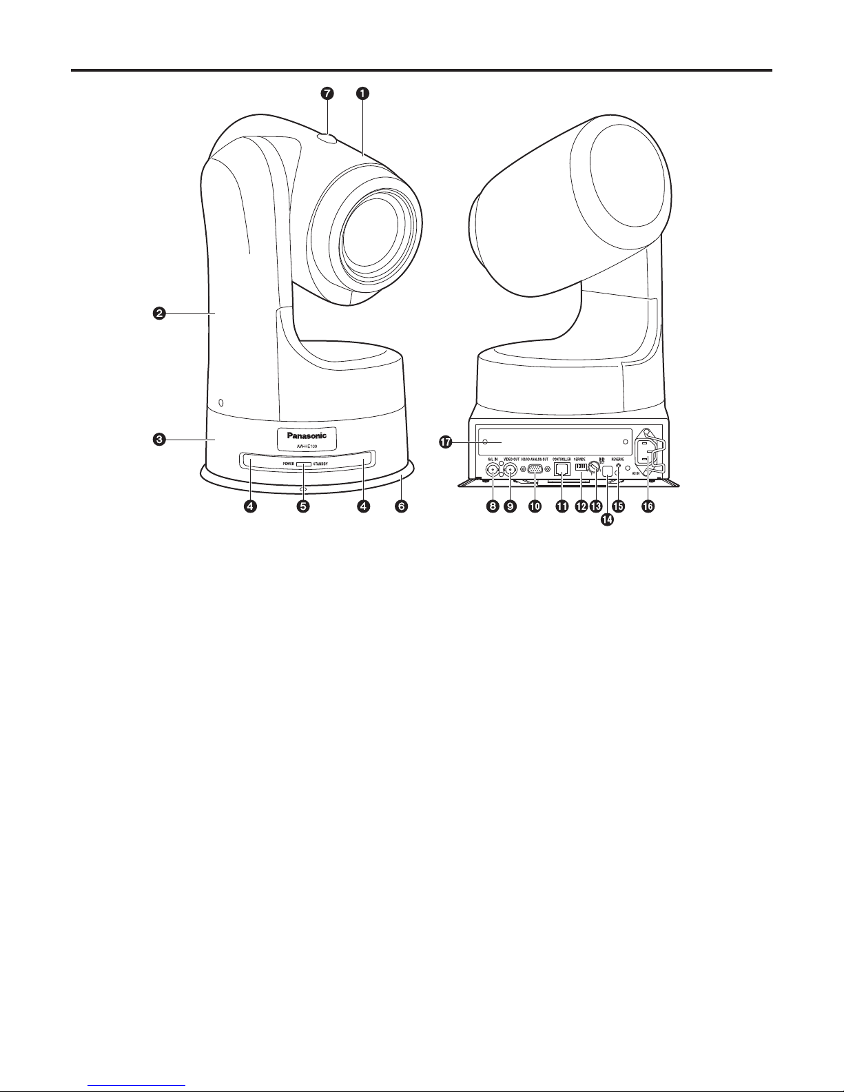
Parts and their functions
1 Camera unit
This rotates in the up and down direction.
2 Rotary head
This rotates in the horizontal direction.
3 Pedestal
4 Wireless remote control signal light-sensing
area (front)
5 Status display lamp
This lights in the following way depending on the status of
the unit.
Orange: When the standby status is established
Green: When the power is on
Red: When trouble has occurred in the unit
Green and blinks twice:
When a signal matched by the remote
control ID has been received from the
accessory wireless remote control while the
power is on
Orange and blinks twice:
When a signal which is not matched by the
remote control ID has been received from
the accessory wireless remote control while
the power is on
10 (E)
ENGLISH
6 Mounting bracket (installed)
7 Tally lamp
This comes on or goes off in response to the control from
the controller but only when “On” has been selected as
the tally lamp use setting.
8 G/L IN connector
This is the genlock signal input connector.
This unit supports the BBS or VBS signal as the genlock
signal.
Connect it to the G/L OUT connector on the cable
compensator (AW-RC400) or other unit.
9 VIDEO OUT connector
This is the output connector for the camera’s composite
video signals. Connect it to a monitor or other such
device. Use a BNC coaxial cable as the connecting cable.
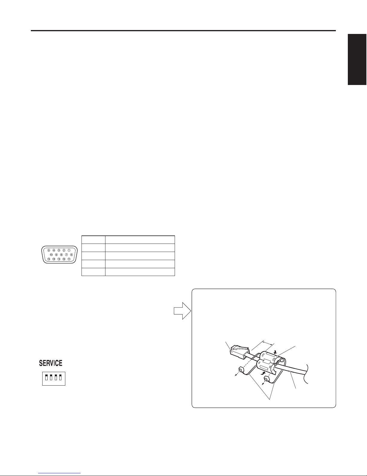
HD/SD ANALOG OUT connector
This is the output connector for the camera’s HD/SD
component video signals.
Use a D-SUB 15-pin connecting cable (VGA cable) or
D-SUB 15-pin and BNC coaxial connector conversion
cable as the connecting cable.
Use a high-quality cable.
Pin No. Signal name
1 Pr (In Y/C mode: C)
2 Y (In Y/C mode: VBS)
3 Pb (In Y/C mode: Y)
4 to 15 GND
CONTROLLER connector
This is the input connector for the control signals of the
camera unit or pan-tilt head unit.
Connect it to the [TO PAN/TILT HEAD] connector on the
controller.
SERVICE switches
These switches are used for maintenance purposes.
Keep them all at the “OFF” position.
IR ID SET switches
These are used to select the ID of the accessory wireless
remote control.
Switches [1] to [4] correspond to the [CAM1] to [CAM4]
buttons on the wireless remote control.
Wireless remote control signal light-sensing
area (rear)
RESERVE button
This reserve button is used for maintenance purposes.
It is not normally used by the user.
AC IN socket
Connect the accessory power cable to this socket.
Option slot
Parts and their functions
Be absolutely sure to attach the filter (supplied)
to the cable connecting to the CONTROLLER
connector .
Attach it at a distance within 30 mm from the
connector, and fasten the both ends of filter with
clampers securely.
Connector 30 mm
Clampers
Filter
Cable
11 (E)
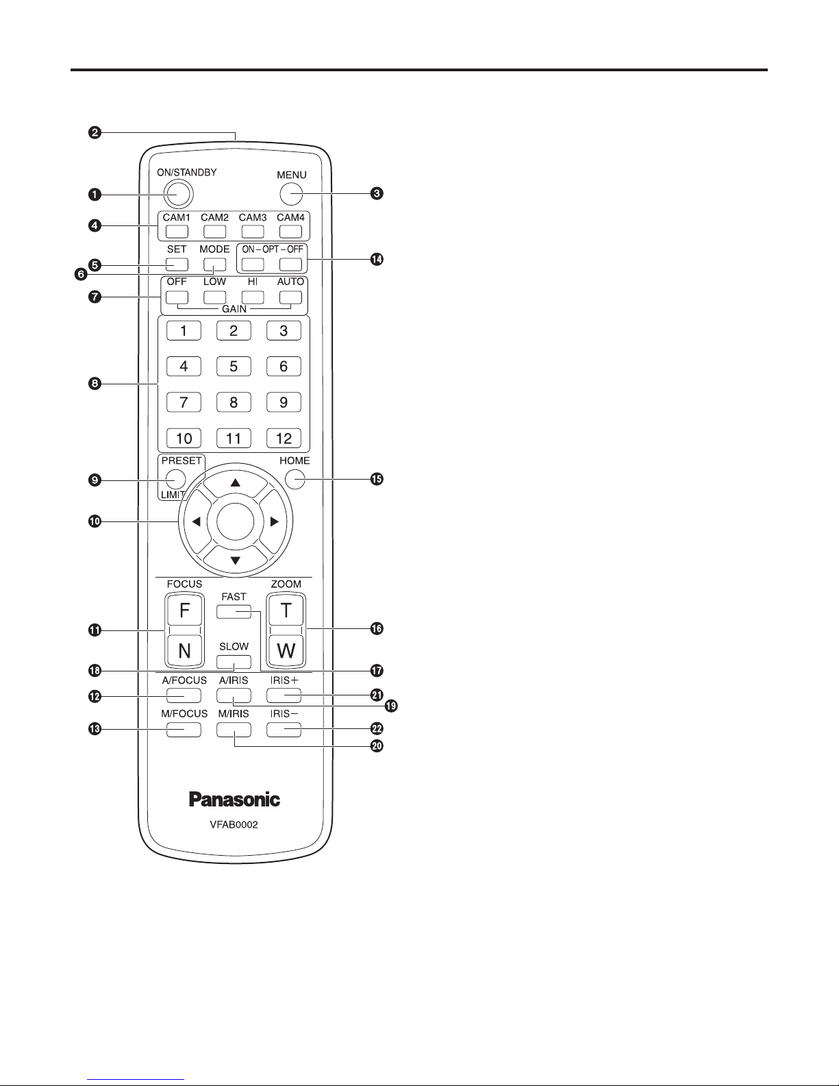
Wireless remote control
1 ON/STANDBY button
Each time this is pressed for two seconds, operation
switches between turning on the unit’s power and
establishing the standby status.
2 Signal transmission window
3 MENU button
Each time this is pressed for two seconds, operation
switches between displaying the unit’s menu and exiting
the menu.
4 CAM1 to CAM4 buttons
These are used to select the units that are to be
operated.
Once a button has been selected, the unit corresponding
to the selected button can be operated.
5 SET button
If this button is pressed for two seconds when the AWC A
memory or AWC B memory is selected by the white
balance adjustment, the black balance and white balance
are automatically adjusted and registered in the memory
currently selected.
6 MODE button
This is used to select the video signals which are output
from the unit.
Each time it is pressed, the signals are switched between
the colour bar signals and camera video signals.
7 GAIN buttons [OFF] [LOW] [HI] [AUTO]
These are used to set the gain.
The gain increase can be set in three steps using the
[OFF], [LOW] and [HI] buttons.
When the [AUTO] button is pressed, the AGC function
is activated, and the gain is adjusted automatically
depending on the light quantity.
The maximum gain of the AGC function can be set using
the menu.
8 Preset memory call buttons [1] to [12]
These are used to call the information on the unit’s
directions and other settings, which have been registered
in the unit’s preset memories No.1 to No.12, and
reproduce those settings.
Settings in preset memories No.13 and above cannot be
called from the wireless remote control.
Parts and their functions

12 (E)
ENGLISH
9 PRESET/LIMIT button
This is used to register the settings in the preset
memories or set or release the limiters.
When a preset memory call button is pressed while the
PRESET/LIMIT button is held down, the information on
the unit’s current direction and other settings is registered
in the call button.
Preset memory call buttons [1] to [12] correspond to the
unit’s No.1 to No.12 preset memories.
Furthermore, the pan and tilt movement range limits
(limiters) are set and released by operating the PRESET/
LIMIT button and the pan/tilt buttons ([], [], [] and
[]). For details, refer to “Setting/releasing the limiters”
(page 53).
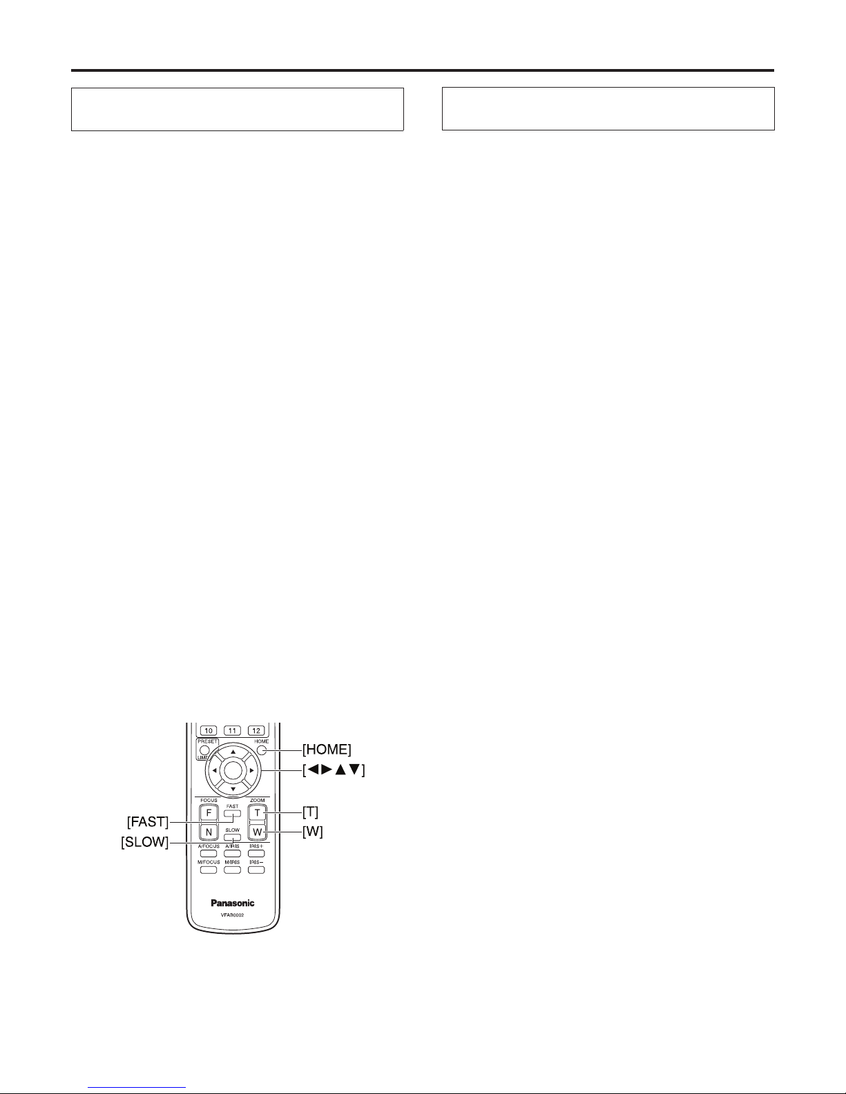
Pan-tilt buttons and menu operation buttons
[] [] [] [] []
These are used to change the unit’s direction.
The unit is tilted in the up/down direction using the []
and [] buttons and panned in the left/right direction
using the [] and [] buttons.
The [] button does not work during tilting and panning.
When the [] or [] and [] or [] buttons are pressed
at the same time, the unit moves diagonally.
The buttons are used for menu operations when the unit
displays the menus.
The menu items are selected using the [] and []
buttons, and the values for the menu items are changed
using the [] and [] buttons.
When a selected item has a sub-menu, the sub-menu will
be displayed by pressing the [] button or [] button.
While the menus are displayed, the [] and [] button
have the same functions.
Bear in mind, however, that if the [] button is pressed
when it is possible to change a value, the value will be
changed by the button.
FOCUS buttons [F] [N]
These are used to adjust the lens focus manually when
the manual setting is established for the lens focus.
The focus is adjusted in the far using the [F] button and in
the near using the [N] button.
A/FOCUS button
This is used when automatically adjusting the lens focus.
M/FOCUS button
This is used when manually adjusting the lens focus.
The FOCUS buttons ([F] and [N]) are used when
performing the actual adjustment.
OPT buttons [ON] [OFF]
These are used for future expansion of the functions.
They are not used at the present time.
HOME button
When this is pressed for two seconds, the unit’s direction
(panning or tilting) returns to the reference position.
ZOOM buttons [T] [W]
These are used to adjust the lens zoom.
The zoom is adjusted in the wide-angle using the
[W] button and in the telephoto using the [T] button.
FAST button
This is used to change the movement speed at which
the panning, tilting, zooming and focusing operations are
performed to the high speed.
The same applies for the movement speeds of panning
and tilting when the information in a preset memory has
been called.
SLOW button
This is used to change the movement speed at which
the panning, tilting, zooming and focusing operations are
performed to the low speed.
The same applies for the movement speeds of panning
and tilting when the information in a preset memory has
been called.
A/IRIS button
This establishes the setting for adjusting the lens iris
automatically in line with the light quantity.
M/IRIS button
This establishes the setting for adjusting the lens iris
manually.
The IRIS+ and IRIS– buttons are used when performing
the actual adjustment.
IRIS+ button
This is used to adjust the lens iris in the opening
direction.
IRIS– button
This is used to adjust the lens iris in the closing direction.
The iris is automatically changed to the automatic
adjustment if the gain is set to the automatic
adjustment while the iris is at the manual adjustment
setting.
If the gain is later returned to the manual adjustment
setting, the iris is also returned to its original value.
The gain is automatically changed back to its
previous value if the iris is set to the manual
adjustment while the gain is at the automatic
adjustment setting.
Notes
Parts and their functions
13 (E)
Concerning the wireless remote control
Operate the wireless remote control from positions less than 10 meters away from the unit.
The wireless remote control may not work when it is pointed from certain angles at the unit.
From a place where the wireless remote control signal light-sensing area (hereafter, “light-sensing area”) can be seen, point
the signal transmission window of the wireless remote control at the light-sensing area, and operate the buttons.
If the unit is installed near fluorescent lights, plasma monitors or other such products or if the unit is exposed to
sunlight, the effects of the light may make it impossible for the unit to be operated using the wireless remote control.
Be sure to follow the steps below for installation and use.
• Take steps to ensure that the light-sensing area will not be exposed to the light from fluorescent lights, plasma monitors
or other such products or from the sun.
• Install the unit away from fluorescent lights, plasma monitors and other such products.
• Operate the wireless remote control at positions within 3 meters from the unit.
• Use a controller that has been connected to the unit using a cable (wired connection).
For about 10 minutes even after the batteries have been removed from the wireless remote control, the selection of
the operation to be performed (the [CAM1], [CAM2], [CAM3] or [CAM4] button which was pressed last) will remain
stored in the memory. When a longer period of time elapses, however, the selection is reset to the status established
when the [CAM1] button was pressed.
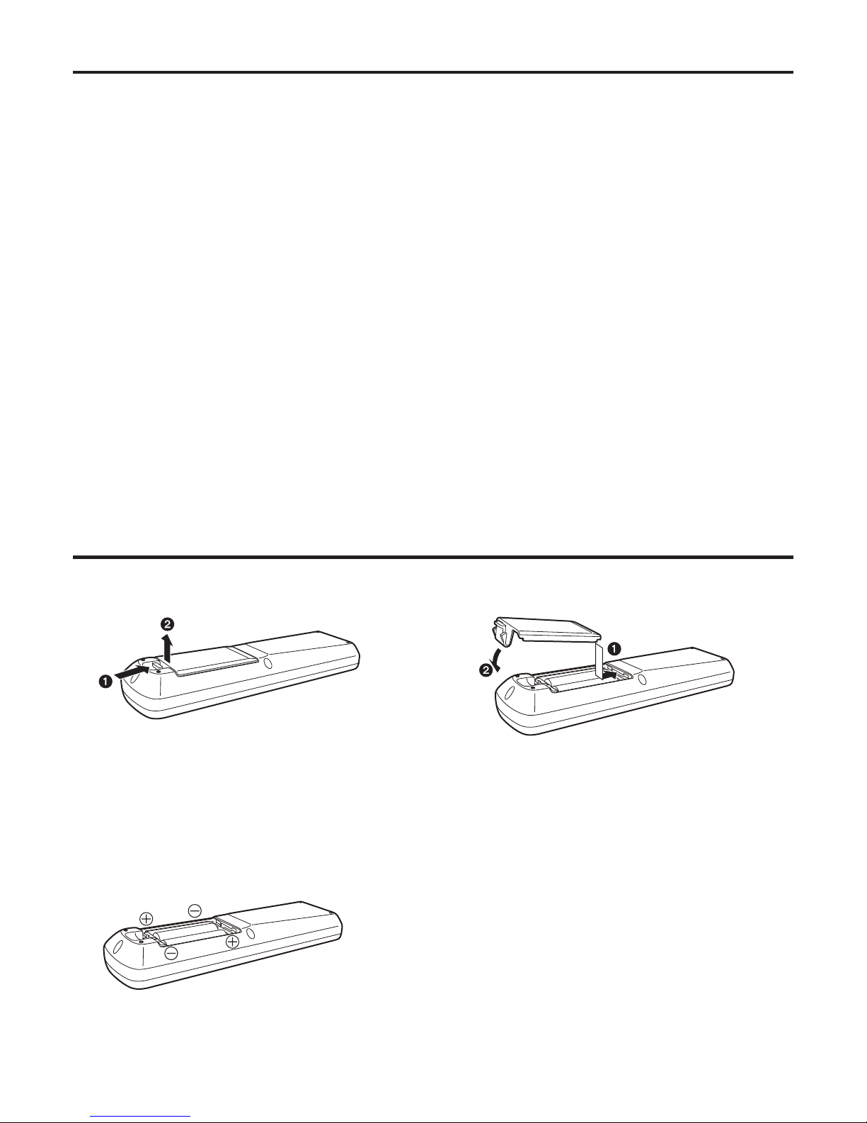
Getting the wireless remote control ready
1 Remove the battery compartment cover.
2 Insert the dry batteries.
Two size “R6” or “LR6” dry batteries (obtained
separately) are used.
Do not use any other kind of batteries. Check which
ends of the batteries are the “+” electrodes and which
ends are the “–” electrodes.
Load the batteries correctly by inserting the negative
end first.
3 Put the battery compartment cover back.
Dispose of batteries that are no longer usable together with
other incombustible garbage or in compliance with the local
ordinances.

14 (E)
ENGLISH
Basic shooting operations
1 Set the subject brightness to the appropriate level.
2 Turn on the power of all the units and devices in the system.
If the accessory wireless remote control is going to be used, be sure to install the two size “R6”
or “LR6” dry batteries inside.
Do not use any other kind of batteries.
(The batteries are obtained separately.)
Note
3 Select the unit to be operated.
Even when using only one unit, it must still be selected from the wireless remote control or controller.
4 Select the shooting mode.
Select one of the four preset shooting modes, each of which corresponds to a set of circumstances in which the subject will
be shot.
Select the mode that satisfies the shooting conditions and suits your preferences.
When continuing to shoot in the same circumstances, there is no need to select another mode.
5 Start shooting.
(After shooting, turn off the power of all the units and devices in the system.)
With the basic operations, it is assumed that the focus, iris and white balance will be adjusted automatically (as per the
factory settings).
If the settings have already been changed and the original settings are to be restored, refer to the “What to do when
encountering problems in the basic shooting operations” (page 22) and “Shooting mode setting menus” (page 44) in “Setting
the menu items”.

15 (E)
How to turn the power on and off
Turning the power on
When performing the operations using the
accessory wireless remote control
1 Set all the power switches of the units
and devices connected in the system to
ON.
This unit does not have a power switch.
When power is supplied to it, the status display lamp
will light up orange.
2 Press one of the [CAM1] to [CAM4]
buttons on the wireless remote control to
select the unit.
3 Press the [ON/STANDBY] button on the
wireless remote control for two seconds.
The power of the unit is turned on, and the initial
settings operation is performed.
The unit’s status display lamp now lights up green.
4 If a multiple number of units are going
to be used, repeat steps 2 and 3 as
required.
The unit’s status display lamp blinks green when a signal
matched by the remote control ID has been received, and
it blinks orange when a signal that is not matched by the
remote control ID has been received.
When performing the operations
using the controller
1 Set all the power switches of the units
and devices connected in the system to
ON.
This unit does not have a power switch.
When power is supplied to it, the status display lamp
will light up orange.
2 Set the [OPERATE] switch on the
controller to ON.
The power of all the cameras connected to the
controller (including the unit) is turned on, and initial
setup is performed.
The unit’s status display lamp now lights up green.
It takes about 30 seconds per unit for the initial settings
operation to be completed. During this period, the unit
cannot be operated.
Before setting the [OPERATE] switch on the controller to
ON, be absolutely sure to set all the power switches of the
units and devices connected in the system to ON.
For further details, refer to the Operating Instructions of the
controller.

16 (E)
ENGLISH
Turning the power off
When performing the operations using the
accessory wireless remote control
1 Press one of the [CAM1] to [CAM4]
buttons on the wireless remote control to
select the unit.
2 Press the [ON/STANDBY] button on the
wireless remote control for two seconds.
The unit’s power is turned off.
The unit’s status display lamp now lights up orange.
3 If a multiple number of units are going
to be used, repeat steps 1 and 2 as
required.
4 Set all the power switches of the units
and devices connected in the system to
OFF.
When performing the operations
using the controller
1 Set the [OPERATE] switch on the
controller to OFF.
The power of all the cameras (including the unit)
connected to the controller is turned off.
The unit’s status display lamp now lights up orange.
2 Set all the power switches of the units
and devices connected in the system to
OFF.
For further details, refer to the Operating Instructions of the
controller.
How to turn the power on and off

17 (E)
Selecting the units
Up to four units can be operated using one accessory wireless remote control.
Up to five units and devices can be operated using one controller.
Select the unit (or units) to be operated from the wireless remote control or controller.
Even when using only one unit, it must still be selected.
When performing the operations using the
accessory wireless remote control
Press the [CAM1], [CAM2], [CAM3] or [CAM4]
button.
The unit’s status display lamp blinks green when a signal
matched by the remote control ID has been received, and
it blinks orange when a signal that is not matched by the
remote control ID has been received.
When performing the operations
using the controller
When the AW-RP655 is connected:
Press the [1], [2], [3], [4] or [5] button of
[CONTROL/PREVIEW MONITOR OUT SEL].
When the AW-RP555 is connected:
Press the [1], [2], [3], [4] or [5] button of
[CONTROL].
When the AW-RP400/AW-CB400 is connected:
Press the [1], [2], [3], [4] or [5] button of
[CONTROL SELECT].
Operations can be performed from both the
AW-RP400 and AW-CB400, but depending on the
settings, it may be possible to perform the operations
using only one of the controllers.
For further details, refer to the Operating Instructions of the
controller.

18 (E)
ENGLISH
Selecting the shooting modes (scene files)
Types of shooting modes
This unit has four preset shooting modes, each of which corresponds to a set of circumstances in which the subject will be shot.
Select the mode that satisfies the shooting conditions and suits your preferences.
The settings can be changed by menu operations.
The results of the white balance and other adjustments are stored in the memory separately by shooting mode.
Be absolutely sure to select the shooting mode before making any adjustments.
Halogen light mode (Halogen)
This mode is suited to shooting indoors at wedding receptions, parties, seminars, event venues, and so on.
Fluorescent light mode (Fluorescent)
This mode is suited to shooting indoors under fluorescent lighting.
Daylight mode (Daylight)
This mode is suited to shooting in daylight conditions.
User mode (User)
This is the mode with the detailed setting items.
Detailed changes to the setting can also be made.
19 (E)
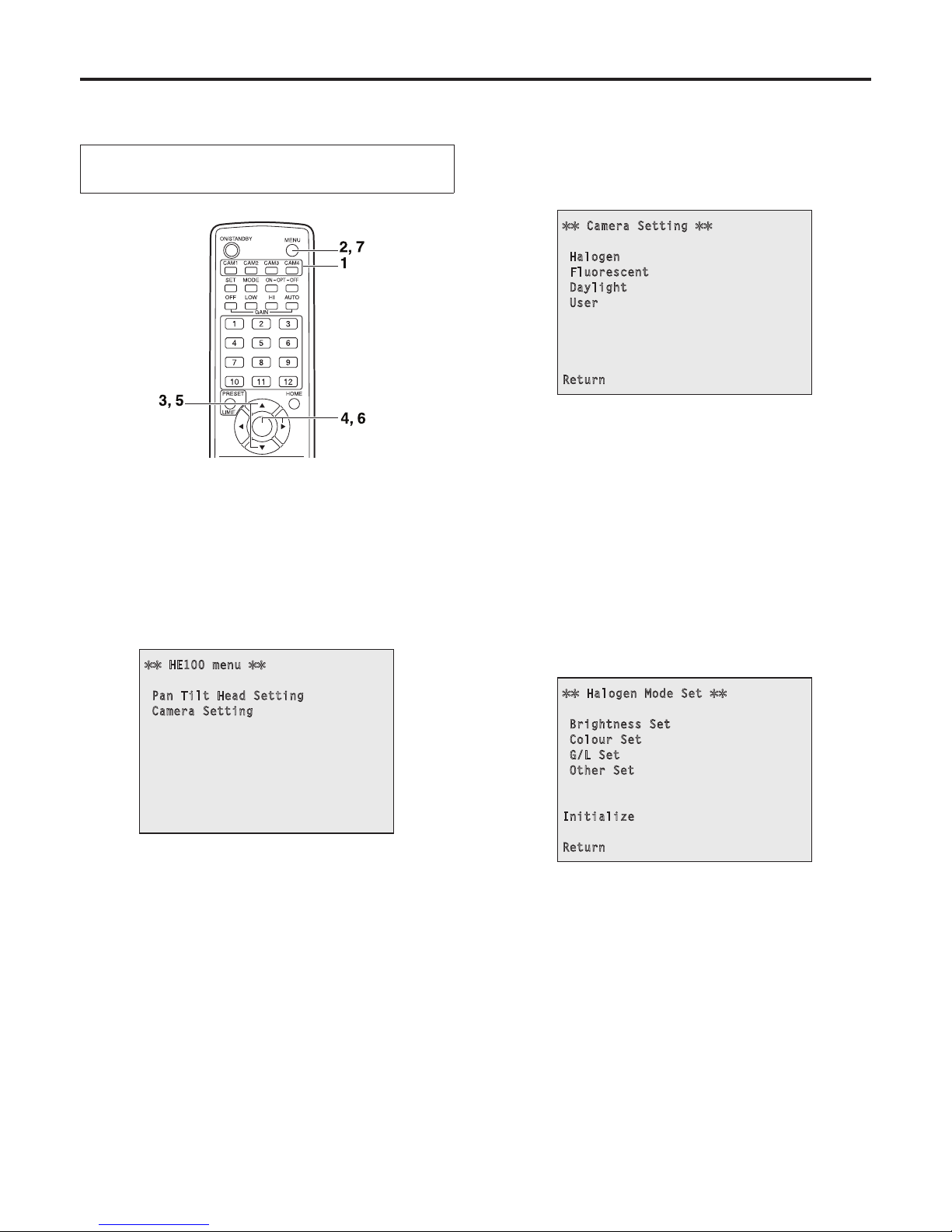
How to select the shooting mode
When performing the operations using the
accessory wireless remote control
1 Press the [CAM1], [CAM2], [CAM3] or
[CAM4] button to select the unit.
2 Press the [MENU] button for two
seconds.
The main menu is displayed.
HE100 menu
Pan Tilt Head Setting
Camera Setting
3 Press the [] or [] button to make
“Camera Setting” blink.
Each time the [] or [] button is pressed, the blinking
item changes.
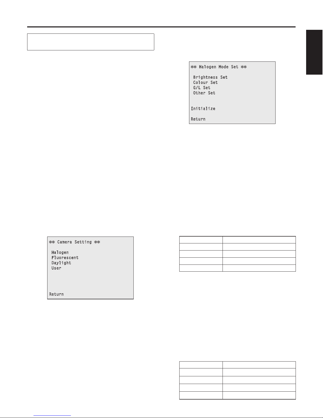
4 Press the [] or [] button.
The “Camera Setting” sub-menu is displayed.
Camera Setting
Halogen
Fluorescent
Daylight
User
Return
5 Press the [] or [] button to make the
shooting mode to be used blink.
Each time the [] or [] button is pressed, the blinking
item changes.
When “Return” is made to blink and the [
] or []
button is pressed, operation returns to the previous
menu.
6 Press the [] or [] button.
The unit is now set to the shooting mode that is
blinking, and a sub-menu is displayed.
Halogen Mode Set
Brightness Set
Colour Set
G/L Set
Other Set
Initialize
Return
Example: Halogen mode
7 Press the [MENU] button for two
seconds.
The menu display is exited.
Selecting the shooting modes (scene files)
20 (E)
ENGLISH
When performing the operations
using the controller
When the AW-RP655 is connected:
1 Press the [1], [2], [3], [4] or [5] button
of [CONTROL/PREVIEW MONITOR OUT
SEL].
2 Press the [MENU] button.
The display on the LCD panel of the AW-RP655
switches to the menu mode.
3 Turn the jog dial (main).
Display “CAMERA SETTING” on the LCD panel.
4 Press the [OK] button.
Display “
OPEN CAMERA MENU?
OK Key” on the
LCD panel.
5 Press the [OK] button again.
The main menu is displayed on the monitor.
6 Press the jog dial (main) to make “Camera
Setting” blink.
7 Turn the jog dial (main) counterclockwise.
Display the “Camera Setting” sub-menu on the monitor.
Camera Setting
Halogen
Fluorescent
Daylight
User
Return
8 Press the jog dial (main) to make the
shooting mode blink.
Each time the jog dial (main) is pressed, the blinking
item changes.
When the “Return” is made to blink and the jog dial
(main) is turned counterclockwise, operation returns to
the previous menu.
9 Turn the jog dial (main) counterclockwise.
The unit is now set to the shooting mode that is
blinking, and a sub-menu is displayed.
Halogen Mode Set
Brightness Set
Colour Set
G/L Set
Other Set
Initialize
Return
Example: Halogen mode
10
Press the [MENU] button or [R/B GAIN/
PED] button.
The menu display is exited.
When the AW-RP555 is connected:
1 Press the [1], [2], [3], [4] or [5] button of
[CONTROL] to select the unit.
2 Press the [1], [2], [3] or [USER] button
of [SCENE FILE] to select the shooting
mode.
Shooting mode [SCENE FILE] button
Halogen [1]
Fluorescent [2]
Daylight [3]
User [USER]
When the AW-RP400/AW-CB400 is connected:
(The following operations are performed using the
AW-CB400.)
1 Press the [1], [2], [3], [4] or [5] button of
[CONTROL SELECT] to select the unit.
2 Press the [1], [2], [3] or [USER] button
of [SCENE FILE] to select the shooting
mode.
Shooting mode [SCENE FILE] button
Halogen [1]
Fluorescent [2]
Daylight [3]
User [USER]
Selecting the shooting modes (scene files)
21 (E)
Shooting
When performing the operations using the
accessory wireless remote control
Changing the camera’s direction
Moving the camera toward the left or right (panning):
Press the [
] or [] button.
Moving the camera up or down (tilting):
Press the [
] or [] button.
Moving the camera diagonally:
Press the [
] or [] button and [] or [] button at
the same time.
Returning the camera to the reference position:
Press the [HOME] button for two seconds.
Using the zoom function
Zooming in (the subject becomes magnified in size):
Use the [T] button of [ZOOM].
Zooming out (the subject becomes reduced in size):
Use the [W] button of [ZOOM].
Switching the direction or zoom speed
Changing the direction or zoom at high speed:
Press the [FAST] button.
Changing the direction or zoom at low speed:
Press the [SLOW] button.
The lens focus control speed is also changed at the same
time.
When performing the operations
using the controller
Changing the camera’s direction
Moving the camera toward the left or right (panning):
Tilt the [PAN/TILT] lever toward L or R.
Moving the camera up or down (tilting):
Tilt the [PAN/TILT] lever toward UP or DOWN.
Moving the camera diagonally:
Tilt the [PAN/TILT] lever diagonally.
Returning the camera to the reference position:
If the controller has a [HOME] button, press the
[HOME] button.
Using the zoom function
Zooming in (the subject becomes magnified in size):
Tilt the [ZOOM] lever toward the TELE direction.
Zooming out (the subject becomes reduced in size):
Tilt the [ZOOM] lever toward the WIDE direction.
Changing the direction or zoom speed
AW-RP655 and AW-RP555:
Press the [SPEED] button.
Each time the [SPEED] button is pressed, the control
speed is switched between the high speed (the button’s
lamp is off) and low speed (the button’s lamp is lit).
The lens focus control speed is also changed at the
same time.
AW-RP400:
Turn the [PAN], [TILT], [ZOOM] dial of
[SPEED CONTROL].
Turning the dial counterclockwise as far as it will go can
disable all operations.
For further details, refer to the Operating Instructions of the
controller.

22 (E)
ENGLISH
What to do when encountering problems in the basic shooting operations
If the trouble is not resolved by taking the action suggested below, refer to “Troubleshooting” (page 55).
When performing the operations using the
accessory wireless remote control
The unit does not move.
Press the [CAM1], [CAM2], [CAM3] or [CAM4] button to
select the unit which is to be operated.
If only one unit is being used, it is normally selected using
the [CAM1] button.
If the unit’s status display lamp is off or lights up orange, it
means that the unit’s power is not on.
Refer to “How to turn the power on and off” (page 15),
and turn on the power.
If the unit’s status display lamp does not blink even
when the wireless remote control is operated near the
unit’s wireless remote control signal light-sensing area, it
means that the wireless remote control’s batteries have
run down.
Replace the batteries.
Multiple colour bands (colour bars) are
displayed.
Press the [MODE] button to switch to the camera picture.
The menu screen is displayed.
Press the [MENU] button for two seconds to exit the menu.
The lens focus is not adjusted automatically.
Press the [A/FOCUS] button to switch to auto focusing.
The camera picture is too light or too dark.
1. Press the [A/IRIS] button to switch automatically to the
lens iris adjustment.
2. Press the [AUTO] button of [GAIN] to switch automatically
to the gain adjustment.
Something is wrong with the colouring of the
camera pictures.
Refer to “Auto tracking white adjustment (ATW)” (page 31),
and switch to “ATW”.
When performing the operations
using the controller
The unit does not move.
Select the unit to be operated by following the procedure
below.
When the AW-RP655 is connected:
Press the [1], [2], [3], [4] or [5] button of [CONTROL/
PREVIEW MONITOR OUT SEL].
When the AW-RP555 is connected:
Press the [1], [2], [3], [4] or [5] button of [CONTROL].
When the AW-RP400/AW-CB400 is connected:
Press the [1], [2], [3], [4] or [5] button of [CONTROL
SELECT].
If the [OPERATE] lamp on the controller is off, it means
that the power of the controller is not on.
If the unit’s status display lamp is off or lights up orange,
it means that the unit’s power is not on. Refer to “How
to turn the power on and off” (page 15), and turn on the
power.
Multiple colour bands (colour bars) are
displayed.
Press the [MODE] button to switch to the camera picture.
The menu screen is displayed.
Press the [MENU] button to exit the menu.
The lens focus is not adjusted automatically.
Press the [EXT(AF)] button to switch to auto focusing.
The camera picture is too light or too dark.
1. Press the [IRIS] button several times to turn on its lamp,
and switch the lens iris adjustment to auto.
2. Press the [GAIN] button several times to turn on its lamp,
and switch the gain adjustment to auto.
When the AW-RP400 is connected, press the [AGC]
button on the AW-CB400.
Something is wrong with the colouring of the
camera pictures.
Refer to “Auto tracking white adjustment (ATW)” (page 31),
and switch to “ATW”.

23 (E)
More advanced operations
Manual shooting
Manual adjustment of focus
Manual adjustment of iris
Manual adjustment of shutter speed
Manual adjustment of gain
Preset memories
Up to 100 settings for the camera direction (panning
and tilting), zoom, focus and also iris can be registered
in the preset memories, and called.
The number of settings that can be registered and
called depends on the type of wireless remote control
(12 settings) or controller that is used for operation.
White balance adjustment
This adjustment is performed to express the white
accurately. Its setting also has an effect on the colour
tones of the entire screen.
It must be performed when using the unit for the
first time or when the unit has not been used for a
prolonged period.
It must be performed when the lighting conditions or
brightness has changed.
Once the white balance has been attained, no further
adjustment is required provided that the unit is going
to be used under the same conditions.
Black balance adjustment
This adjustment is performed to express the black
accurately. Its setting also has an effect on the colour
tones of the entire screen.
It must be performed when using the unit for the
first time or when the unit has not been used for a
prolonged period.
It must be performed when the ambient temperature
has changed significantly and at the change of the
seasons.
Once the black balance has been attained, no further
adjustment is required provided that the unit is going
to be used under the same conditions.
Black level (total pedestal) adjustment
This adjustment is performed to align the black level
(pedestal level) of a multiple number of cameras.
Ask your dealer to perform this adjustment.
Genlock adjustment
This adjustment is performed to achieve phase
alignment by applying external synchronization
(genlock) when a multiple number of cameras will be
used or when the unit will be used in combination with
other devices.
Ask your dealer to perform this adjustment.

24 (E)
ENGLISH
Manual shooting
Manually adjusting the focus
The lens focus can be adjusted manually.
When performing the operations using the
accessory wireless remote control
1 Press the [M/FOCUS] button to switch the
focus to manual adjustment.
2 Press the [F] or [N] button of [FOCUS],
and adjust the focus.
When the [F] button is pressed, the focus moves further
away (far); conversely, when the [N] button is pressed,
it moves nearer (near).
The speed of focusing and other adjustments can
be switched to fast or slow by pressing the [FAST] or
[SLOW] button, respectively.
3 If necessary, press the [A/FOCUS] button
to return the focus to the automatic
adjustment.
When doing the adjustment
using the controller
When the AW-RP655 is connected:
1 Press the [EXT(AF)] button to switch the
focus to manual adjustment.
2 Adjust the focus manually by turning the
dial above the lit [FOCUS] lamp whether
it is the lamp of the [PAN/TILT] lever or
[ZOOM] lever.
Furthermore, every time the [SPEED] button is
pressed, the speed of the focusing and other
adjustments can be switched to fast or slow.
3 If necessary, press the [EXT(AF)] button
to return the focus to the automatic
adjustment.
When the AW-RP555 is connected:
1 Press the [EXT(AF)] button to switch the
focus to manual adjustment.
2 Adjust the focus manually by tilting the
[FOCUS] lever.
Furthermore, every time the [SPEED] button is
pressed, the speed of the focusing and other
adjustments can be switched to fast or slow.
3 If necessary, press the [EXT(AF)] button
to return the focus to the automatic
adjustment.
When the AW-RP400 is connected:
1 Press the [EXT(AF)] button to switch the
focus to manual adjustment.
2 Adjust the focus manually by turning the
[FOCUS] dial near the [ZOOM] lever.
Furthermore, the speed of the focusing can be adjusted
by turning the [FOCUS] dial of [SPEED CONTROL].
Turning the dial counterclockwise as far as it will go can
disable all operations.
3 If necessary, press the [EXT(AF)] button
to return the focus to the automatic
adjustment.
When the focus is set to manual, the subject may
go out of focus during zooming. Therefore, the unit
comes with a function which compensates for this.
(Focus compensation during zooming function)
This function was set to ON at the factory.
If the function has been set to OFF, either adjust the
focus, as required, after zooming or set the focus to
auto.
When the ON/OFF setting of auto focus (AF) is
switched from AW-RP400, use the OPTION SW
after allocating the “EXT” function to it.
Notes

25 (E)
Manually adjusting the iris
The lens iris can be adjusted manually.
When performing the operations using the
accessory wireless remote control
1 Press the [M/IRIS] button to switch the
iris to manual adjustment.
2 Adjust the iris using the [IRIS+] or [IRIS–]
button.
Press the [IRIS+] button to adjust the lens iris in the
opening direction; conversely, press the [IRIS–] button
to adjust the lens iris in the closing direction.
3 If necessary, press the [A/IRIS] button
to return the iris to the automatic
adjustment.
When doing the adjustment
using the controller
When the AW-RP655 is connected:
1 Press the [IRIS] button several times to
turn off the button’s lamp and switch to
manual adjustment.
2 Adjust the iris manually by turning the
dial above the lit [IRIS] lamp whether it
is the lamp of the [PAN/TILT] lever or
[ZOOM] lever.
3 If necessary, press the [IRIS] button
several times and turn on its lamp
to return the iris to the automatic
adjustment.
When the AW-RP555 is connected:
1 Press the [IRIS] button to turn off its lamp
and switch to manual adjustment.
2 Turn the [LEVEL] dial of [IRIS] to adjust
the iris manually.
3 If necessary, press the [IRIS] button to
turn on its lamp and switch to automatic
adjustment in order to return the iris to
automatic adjustment.
When the AW-RP400/AW-CB400 is connected:
1 Press the [IRIS] button several times to
turn off the button’s lamp and switch to
manual adjustment.
2 Turn the [IRIS] dial to adjust the iris
manually.
3 If necessary, press the [IRIS] button
several times and turn on its lamp
to return the iris to the automatic
adjustment.
The iris is automatically changed to the automatic
adjustment if the gain is set to the automatic
adjustment while the iris is at the manual adjustment
setting.
If the gain is later returned to the manual adjustment
setting, the iris is also returned to its original value.
The gain is automatically changed back to its
previous value if the iris is set to the manual
adjustment while the gain is at the automatic
adjustment setting.
Notes
Manual shooting
26 (E)
ENGLISH
Manual shooting
Manually adjusting the shutter
speed
The shutter speed can be set using two methods. One is
a method that specifies the time (where a time such as
1/250 sec. is designated), and the other is a method that
specifies the frequency (where synchro scan, 60 Hz, etc. is
designated).
When shooting a TV screen or PC monitor screen, the
horizontal noise generated when the screen is shot can
be minimized by adjusting the frequency to the screen
frequency using synchro scan.
Synchro scan can be designated in the user mode only.
When performing the operations using the
accessory wireless remote control
Perform the adjustments on the Camera Setting menu.
For further details, refer to the [Step], [Shutter Mode] and
[Step/Synchro] items on page 46.
When doing the adjustment
using the controller
The procedure is the same as for “When performing the
operations using the accessory wireless remote control” in
“Basic menu operations” (pages 39 to 41).
When the AW-RP555 is connected, the adjustments can
also be performed by following the steps below.
1 Press the [SHUTTER] button and turn its
lamp on.
The shutter speed set ahead of time is selected.
2 If necessary, press the [SHUTTER] button
and turn its lamp off in order to return the
shutter to the OFF setting.
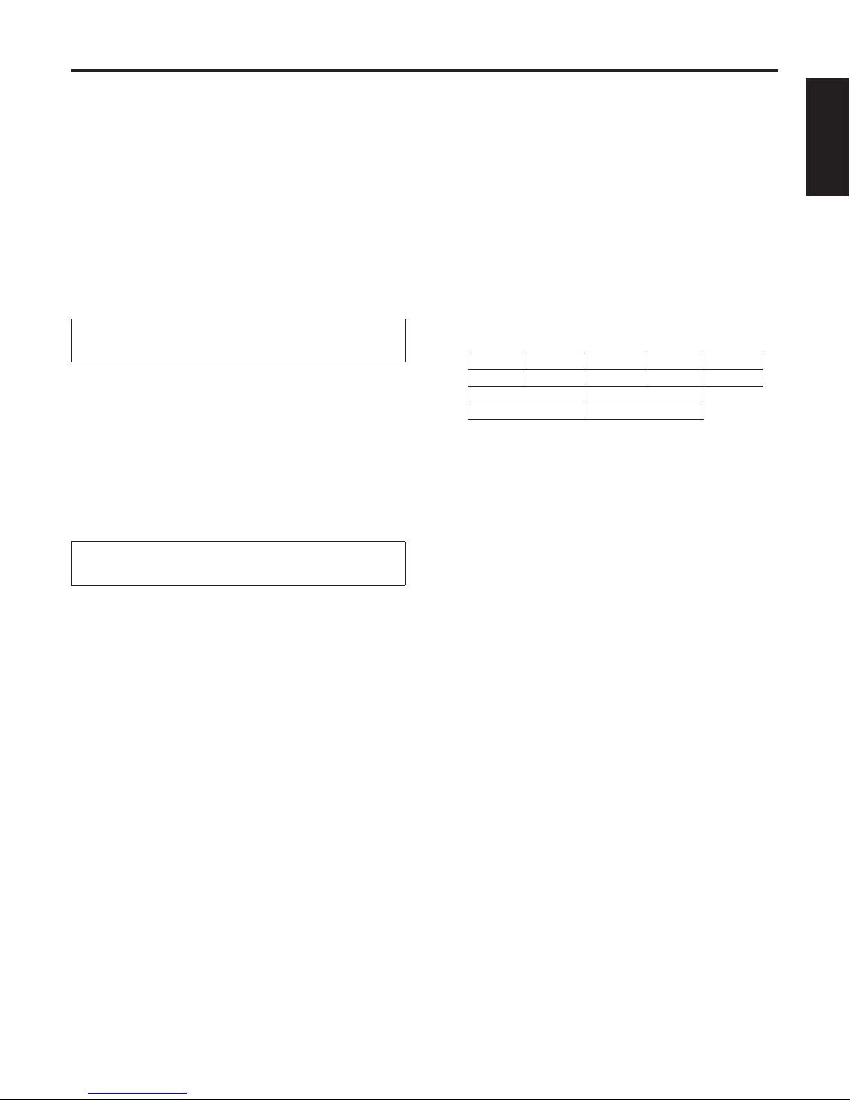
Follow the steps below to set the shutter speed using
the AW-RP555.
1 With the [MEMORY] button still held
down, press the [SHUTTER] button.
The [PRESET] [1] to [5], [8] and [10] buttons blink
alternately.
2 Press one of the [1] to [5] buttons or the
[8] or [10] [PRESET] button — whichever
button corresponds to the shutter speed
which is to be set.
Any of the shutter speeds in the table below can be set.
[1] [2] [3] [4] [5]
1/120 1/250 1/500 1/1000 1/2000
[8] [10]
Synchro Scan OFF
Any change in the shutter speed is reflected the next
time the [SHUTTER] button is pressed and its lamp
is turned on.
When OFF is selected, the shutter will not operate
even when the [SHUTTER] button is pressed.
Select the synchro scan setting on the menu.
The shutter speed setting performed here is
stored in the memory even when the power of the
AW-RP555 is turned off.
For further details, refer to the Operating Instructions of the
AW-RP555.
27 (E)
Manual shooting
Manually adjusting the gain
There are two ways to adjust the gain. One way involves
using the buttons on the wireless remote control or
controller; the other way involves using the Camera Setting
menu.
The gain can be adjusted more precisely using the Camera
Setting menu. For further details, refer to the [Gain] item on
page 46.
When performing the operations using the
accessory wireless remote control
1 Press the [OFF], [LOW] or [HI] button.
These buttons enable the gain increase to be selected
in three steps.
2 If necessary, press the [AUTO] button in
order to return the gain to the automatic
adjustment (AGC).
When performing the operations
using the controller
When the AW-RP655 is connected:
1 Press the [GAIN] button and turn on the
[MANU] lamp.
The preset gain increase amount is now selected.
For further details on the gain increase amount setting,
refer to the Operating Instructions of the AW-RP655.
2 If necessary, press the [GAIN] button and
turn on the [AUTO] lamp in order to return
the gain to the automatic adjustment
(AGC).
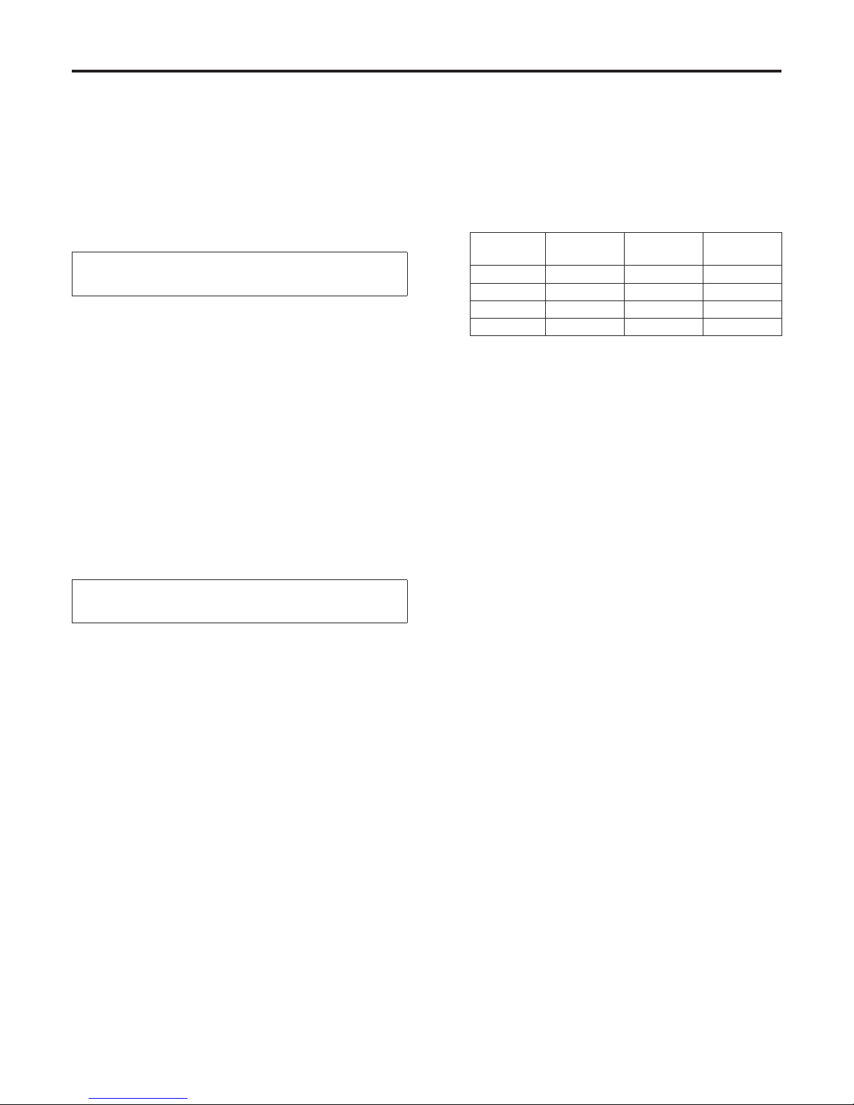
When the AW-RP555 is connected:
1 Press the [GAIN] button to turn off its
lamp.
Each time this button is pressed, one of the three gain
increase amounts can be selected in sequence.
The current status is displayed as follows.
[MANU]
[L] button
[MANU]
[H] button
[GAIN]
button
0 dB Off Off Off
LOW Lit Off Off
HIGH Off Lit Off
AUTO Off Off Lit
2 If necessary, press the [GAIN] button
several times and turn on its lamp in
order to return the gain to the automatic
adjustment (AGC).
When the AW-RP400/AW-CB400 is connected:
(The following operations are performed using the
AW-CB400.)
1 Press the [0dB], [L], [M] or [H] [GAIN]
button and turn on its lamp.
These buttons enable one of the four gain increase
amounts to be selected.
The gain increase amounts can be set in the [L], [M]
and [H] buttons.
For further details, refer to the Operating Instructions of
the AW-CB400.
2 If necessary, press the [AGC] button and
turn on its lamp in order to return the gain
to the automatic adjustment (AGC).
In any case, the maximum gain of the automatic adjustment
can be set by the menu.
For further details, refer to the [AGC Max Gain] item on
page 46.

28 (E)
ENGLISH
Preset memories
This unit enables up to 100 settings for the camera direction (panning and tilting), zoom, focus and iris to be registered in its
preset memories, and called.
However, the number of settings that can be registered and called depends on the type of wireless remote control or controller
that is used for operation.
The status as to whether the manual settings or auto settings are applicable is not registered for the focus and iris.
The current focus and iris values are registered.
The focus and iris values can be recalled only when the manual settings are applicable.
When performing the operations using the
accessory wireless remote control
Twelve settings (preset No.1 to No.12) can be registered and
called using the wireless remote control.
The [1] to [12] buttons correspond to the unit’s preset
memories No.1 to No.12.
Registering the settings in the preset memories
1 Display the picture to be shot on the
monitor.
Operate the pan, tilt or zoom buttons to determine the
camera angle.
Adjust the focus and iris if they need to be adjusted.
2 While holding down the [PRESET] button,
press the button corresponding to the
preset memory number.
If a preset memory number with an already
registered setting has been selected, the existing
setting will be erased and replaced with the new one.
Calling the settings of the preset memories
1 Press the button in which the preset
memory setting has been registered.
When performing the operations
using the controller
When the AW-RP655 is connected:
Up to 50 settings can be registered and called.
The [1] to [50] buttons of [TRACING/PRESET MEMORY]
correspond to the unit’s preset memories No.1 to No.50.
Registering the settings in the preset memories
1 Set to the preset memory mode.
Press the [TR/PSET] button to turn off its lamp.
2 Set to the memory recording mode.
Press the [M.LOCK] button to turn off its lamp.
3 Display the picture to be shot on the
monitor.
Operate the [PAN/TILT] lever and [ZOOM] lever to
determine the camera angle.
Adjust the focus and iris if they need to be adjusted.
4 Hold down the [MEMORY] button.
The buttons among the [1] to [50] buttons of
[TRACING/PRESET MEMORY] in which settings can
be registered now start blinking in sequence.
Preset memory settings cannot be registered in
buttons whose lamps are off (since they contain
tracing memory settings).
5 With the [MEMORY] button still held
down, press the button of the preset
memory number in which the setting is to
be registered.

29 (E)
Calling the settings of the preset memories
1 Set to the preset memory mode.
Press the [TR/PSET] button to turn off its lamp.
2 Press the button among the [1] to [50]
buttons of [TRACING/PRESET MEMORY]
in which the desired setting was
registered.
Erasing preset memory settings
1 Set to the preset memory mode.
Press the [TR/PSET] button to turn off its lamp.
2 Set the memory recording mode.
Press the [M.LOCK] button to turn off its lamp.
3 Hold down the [RESET] button.
The buttons among the [1] to [50] buttons of
[TRACING/PRESET MEMORY] whose settings can be
erased now start blinking in sequence.
The settings for the buttons whose lamps are off
cannot be erased (since they contain tracing memory
settings).
4 With the [RESET] button still held down,
press the button of the preset memory
number whose setting is to be erased.
When the AW-RP555 is connected:
Up to 10 settings can be registered and called.
The [1] to [10] buttons of [PRESET] correspond to the unit’s
preset memories No.1 to No.10.
Registering the settings in the preset memories
1 Display the picture to be shot on the
monitor.
Operate the [PAN/TILT] lever and [ZOOM] lever to
determine the camera angle.
Adjust the focus and iris if they need to be adjusted.
2 Hold down the [MEMORY] button.
The buttons among the [1] to [10] buttons of [PRESET]
in which settings can be registered now start blinking in
sequence.
3 With the [MEMORY] button still held
down, press the button of the preset
memory number in which the setting is to
be registered.
Calling the settings of the preset memories
1 Press the button among the [1] to [10]
buttons of [PRESET] in which the desired
setting was registered.
When the AW-RP400 is connected:
Up to 50 settings can be registered and called.
The [1] to [50] buttons of [PRESET MEMORY] correspond to
the unit’s preset memories No.1 to No.50.
Registering the settings in the preset memories
1 Display the picture to be shot on the
monitor.
Operate the [PAN/TILT] lever and [ZOOM] lever to
determine the camera angle.
Adjust the focus and iris if they need to be adjusted.
2 Hold down the [MEMORY] button.
3 With the [MEMORY] button still held
down, press the button of the preset
memory number in which the setting is to
be registered.
Calling the settings of the preset memories
1 Press the button among the [1] to [50]
buttons of [PRESET MEMORY] in which
the desired setting was registered.
Preset memories
 Loading...