

Page 1
Colour
Video Camera
AW-F575E
Electric Industrial Co., Ltd.
PO
Box
288.
Osaka 530-8691, J a p a n
Page 2
MAJOR
OPERATING CONTROLS
AND THEIR
FUNCTIONS
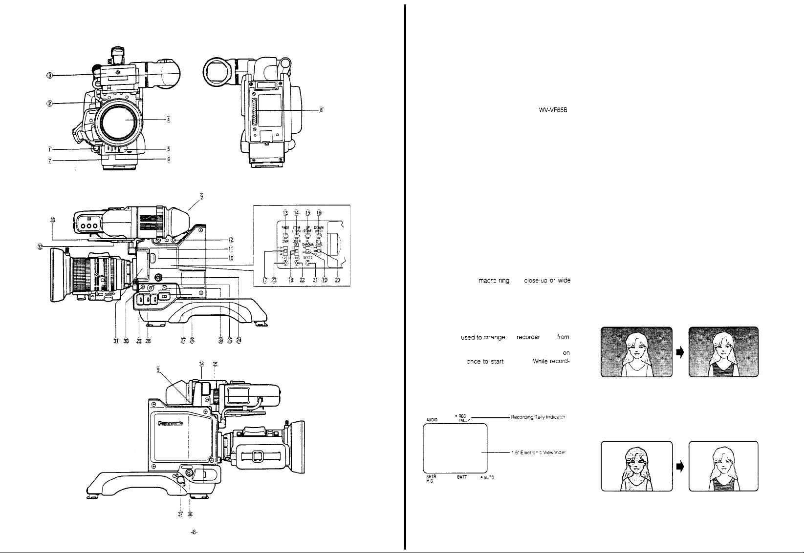
CAMERA HEAD AW-F575HE
1. Lens
Connector (12-pin) (LENS)
Connect the lens
2. Viewfinder
Connect
Electronic Viewfinder to this
Note:
VW-VF65B to this connector,
Conversion
Refer to page 28 for details.
3. 1.5”
Electronic
This small
shows
viewfinder
adjustable up
(13/16"). Further the viewfinder
by up to 45 mm (1-
forth.
4. Auto Iris
Thls is a high-quality zoom lens offering automatic
well
as manual
The
lens features
aperture
Picture size may
through
Simply
angle recording. M
objects up to
Refer to
cable to
this
connector
Connector (12-pin)
the
viewfinder
When connecting the 5" Electronic Viewfinder
Cable
Viewfinder
1.5"
(1-3/8"
exactly the image picked up
can be
titled
and
down
Refer to page
rotate
3/4") and
18 for
Serfvo
Control Zoom
iris control
a bayonet mount F1.4 Maximun
be
use
of
the zoom feature.
the mac:z nng
acro shooting is
5 cm (15/16")
page 16 for
details .
(VIEWFINDER)
cable from the
connector
use the
supplied with
actual
image size) monitor
30º from
magnified
by
approximately
20 mm
details.
and
for
from the
horizontal
may be
Lens
servo
by up to 14
15’
the
by
(3/4") back
control
close-uo or wde
po
or
5’
Viewfinder
the lens.
and it
20 mm.
slid laterally
and
zoom
times
ssible of
lens surface
The
is
as
6. Auto
White/Auto
(AUTO
This switch sets
automatically
AWC:
ance when
(28) is
White
A NG’ or ‘AWC B NG’
viewfinder or
the
Two
such
the
AWC B
HOLD:
set at the AWC or ABC
if so
ABC:
ance.
‘ABC NG’
the Auto
lights
Note: The
black
cates that the
formed and
completed.
Fl
maxlmurr
7.
Lens
Iris
(LENS
This
switch can be
compensate for
object is brightly lit against a dark
this switch to
the
lens iris
Black Set Switch
W/B
BAL
AWC/HOLD/ABC)
the
white balance
as
follows
This position is used
the White
set to the AWC A or AWC B
balance
adjustment is requiered
when the Auto
viewfinder
lights
white
balance
as
memory. I
positions
In
this position,
desired
This position is used
Black balance
picture will
balance is
Selection
IRIS:
by a
settings for two light
indoor
and
outdoor
n
this
case
are
used
the
for at
least one year.
starts blinking in the viewfinder or
1/2 OPEN / NOR / 1/2 CLOSE)
the
adjustment is required
Warning Indicator in
flash in
being
adjustment is currently being per-
will cease once the adjustment is
Switch
used to
unusual lighting conditions
1/2 CLOSE position.
1/2
F
stop
and black balance
for
setting
Balance
set
the
Selection Switch
starts blinking in
Warning Indicator in
can be
both the
AWC A and
white
and black balances
position
can be
for
setting
the black bal-
the
the viewfinder while
set.
This flashing indi-
the lens iris opening to
background, set
This will close
white
bal-
position
when ‘AWC
the
sources,
retained in
held fixed
when
when
viewfinder
the
if
the
5.
VTR Start/Stop
This
button is
pause
in
the
the
ing,
the
Recording/Tally indicator
(101) on
.
When this buttonis
is
set to
Recording/Tally Indicator
Button
used fo crsnge
(Recording Pause) to recording
same
way as the
lens. Press zxe to s!art
Tally Indicator in
the viewfinder al
.
the Pause mode (Recording Pause) and the
(VTR) (parallel operation)
the
recorder
recording.
viewfinder
light,
and
lights.
Tally Light will
and
VTR Start/Stop Button
the
(9)
so
pressed
once more
and
mode
frOm
functions
(92)
Whlle record-
and the
the Tally
Light
the recorder
go off.
on
- 7 -
If
the
object is relatively
bright,
set the
will open
the
switch to
lens iris
by a
dark and
the
1/2
1/2
F
stop
the
background
OPEN
is
position. This
Page 3
At
the
normal (NOR)
with
normal
Notes:
1 If
this switch is used,
detent
NOR
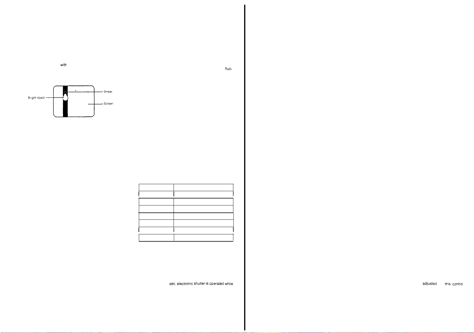
2 If
the
camera is
object, such
(s
mear)
peculiar phenomenon
normal. T
ing scenes wth
could also
3. Set
this switch to
era is
used
(RCU)
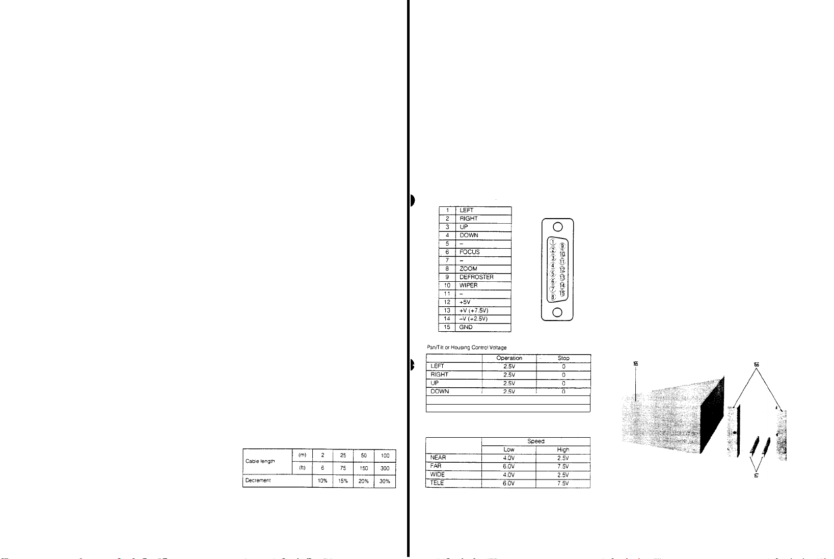
8. 68-pin Multi Connector
When
mounting the
500AE Camera
tors on
the Camera Head and
Camera
Adaptor.
9.
Recording/Tally
This indicator changes
depending on
This indicator lights
recordlng mode
and
informs that
Tally Indicator also lights
system operation
Unit
and
Special Effects Generator. I
not loaded or
mechanism is working improperly, this indicator
start blinking to warn
Indicator lights green
shutter on
mode.
camera is set to the recordlng mode and the
on
mode is
selected.
Note: If a
portable VTR is not connected to
era, the
position,
the
lens
iris
openings
position after
aimed at an extremely bright
as
the sun or a lamp, vertical bars
may
appear in the picture. This is a
ry as
much
extremely bright light, as this
be
harmful to
the NOR
together
with
dockable VCR or
Adaptor, engage the 68-pin connec-
Indicator
to one of these three colours,
the camera mode.
red when the camera is set to the
(through
the
the
scene is being recorded.
together
the tape end is reached, or if the
the
when
This indicator lights yellow
Recording/Tally Indicator will not light.
lens is operating
be
sure to return it to
use.
of the
CCD
as
possible to avoid shoot-
the camera.
position
when
the
Remote
VCR/VTR Adaptor, or
(REC
TALLY)
three colours,
VTR Start/Stop Button).
when the camera is in
with
the Remote Control
n case a tape
operator
of
such faults. T
the
camera is set to
and is
the
Control
the AW-AD
when the
the cam-
the
quite
cam-
The
servo
shutter
Unit
full
will
the
12.
Back
Light
10.
Scene File Selection
(SCENE FILE, USER A/B/1/2/3)
This switch is used to select
conditions
for
ture
1:
Studio
Mode
This position is suitable
condition
Note:
2000 lux, 3200º K at
ibis
is
his
2: ENG Mode
This position is suitable
rescent, halogen or outdoor lighting
Note: The
outdoor lighting
Menu.
3: Low
Light
This position is suitable
shooting
USER A/B:
desired level
11.
Electronic Shutter On/Off Switch
ON/OFF)
This switch is used to select
On/Off mode.
When setting this switch
speed is in a speed
Notes:
1
In
the electronic shutter
object/scene is taken in a short period of time.
Therefore,
scene illumination.
Shutter
Speed
1/120 sec.
1/250 sec.
1/500 sec.
1/1000 sec.
1/2000
sec.
1/4000
sec.
1/10000 sec. 80000 lux
2. In
the electronic shutter operation,
smear
intensity is required
shooting scenes which contain
objects. Refer to
THE CCD on
3
The
white
-
1/10000
the camera is in
Switch
the
various scenes to obtain
This level is adjusted under
selection of fluorescent, halogen or
Mode
The camera
by
the user
set by the
higher shutter
of CCD is
emphasized since greater light
page
balance may be
sec. electronlc shutter IS operated while
the +18 dB high gain condition
most suitable
the
for
shooting in normal
the
F8
for
shooting under fluo-
can be
for
conditions
the
to
the ON position, the shutter
menu
operatlon,
speeds
Minimum Illumination (at F8)
16000
as
mentioned above. Avoid
PECULIAR PHENOMENA OF
59
disturbed if the
condition of
selected on the Main
low illumination level
can be set to
(SHUTTER,
Electronic
the light
require g
1000
lux
2000
lux
4000 lux
8000
lux
lux
32000 lux
the
extremely
camera
best
pic
Shutter
of the
reater
vertical
bright
1/1000
the
(BACK
When backlight
-
for a
Note: Be
13. Page Switch (PAGE)
By
User
on
14.
Item / I Noise Suppress
When the
this switch is used to move
items in
When the
the I
this switch.
Note:
15.
Up/Zone Switch (UP/ZONE)
When
the On
level of an item
switch.
When
the
zone into
switch
Notes:
1
2. The
16.
Down/Level
When the
the Off mode of an
level
When the
the
viewfinder
Picture images exceeding a specified level
will
Note: The zebra
17.
Clean
Switch
This switch is used to improve
screen
Compensation Switch
LIGHT COMP
clear picture.
sure to
the A (Auto)
Light Control
repeated pressing
Set
menus
the
monitor.
User
the
User
Noise
Suppress in the
Noise
pressed
(20) is set to the HIGH or LOW
the User
mode of an
the User
display on or
the
The marker shows the
ture
and
of the
picture
center
can be set by the Sub
User
of an
item
User
display On/Off of
can be
produce a zebra
DNR
(DNR OFF, LOW, HIGH)
ON/OFF)
affects
the
picture, turn on this
set the Auto
position or activate the Electronic
of
this switch,
can be changed in
Switch
Set
Switch is
set to the
menu.
Set
of
the I axis on
when the
Set
can be
Set
viewfinder
might not coincide with
marker
Indicator Switch
Set
can be decreased in the
Set
level
(Digital Noise
the cursor to
Switch is
menu
Detail Level Selection Switch
Switch is
set to the
item
can be
increased in the menu
Switch is
off of
the
can be
electronic
on/off
Menu
Switch is
set to
item
can be
Switch is
set to
the zebra
controlled
by
pattern barely visible
can be set by the Sub
Reduction)
switch
Iris Button
of the
lens to
the
Initial
Set and
the viewfinder or
(ITEM/I-NS)
position 1 or
the various
set to
the
OFF
can be
the
vector
selected and/or the
set to the OFF
centre marker or safety
and type of
(DOWN/IND)
the position 1 or
selected and/or
the
pressing this switch
the
position,
selected
can be
position
position
1 or 2,
by
position
selected
by
centre of
the pic-
the
optical
centre
safety zone
the
menu
OFF
position,
pattern into
S/N ratio on the
the
(95
Menu
Selection
by
sup-
this
this
2.
IRE)
2,
19.
User
Set
Switch (USER
By setting this switch to
ed by the
viewfinder
By setting this switch to the position
ed by the
the viewfinder and the monitor.
To
the
menu is
Note: To
19. High Light
This Switch is used to obtain
high
By
high level
Ser menu
Note: When
20.
Detail Level Selection Switch
(DTL,
The
switch in three steps. Set this switch to
position while observing the sharpness
Note: When
21.
Recording
The
viewfinder under REC
(25) is
pressing either this button or the one on the
VTR.
checked by
new recording
end of the
Note: The
22.
Lens
The auto Iris
When
the camera and make
this
Scene File Switch is displayed in the
and
Scene File Selection Switch is displayed in
display the
monitor
set
kept
select
Scene File Selection Switch
position while pressing
Check Button
When
setting the Scene File Selection Switch
to
the
USER position without
Check Button,
or
B is
displayed.
Chroma Switch
brightness condiition.
setting this switch to the ON position. The low or poslrion.
can be
tion, the object in
might
be
LEVEL-HIGH/LOW/OFF)
detail/aperture level
recordlng or
to LOW position.
Time
accumulated
pressed.
Thus
first pressing this button at
recording
REC
the
one dilsplayed on
ferent.
Iris Control (IRIS)
replacing the lens, check
control if
SET
1, 2, OFF)
the
position
menu setting is available.
normal
picture in the viewfinder or on
this switch to
under
the last
the
(25)
the
selected in the
the
HL
coloured.
over modulation
playing back
Reset
recording
The
total recording
and
TIME
level
can be
required
the OFF
condition)
USER
A or USEREB Menu, . set the
the Page
last selected menu
(HL
the goad
CHROMA is
the
high brightness condition
can be
the
Button
time is displayed in
TIME
while
tune
can be
time
then checking REC TIME at
by
pressing
displayed in the viewfinder
the AG-7450A might be dif-
adlusted
any necessary adjustment with
1, a
Menu select-
2, a
Menu select-
position
(10) to
Switch
the Page
CHROMA ON/OFF)
picture in the
Sub
Menu or User
set to
the HIGH posi-
selected
of the
has
occurred with
VTR,
set
(RESET)
the
Check Button
reset to
can
easily
the
the check
by
thls conir
the
output signal of
(The
the USER
(13)
Switch or
of
USER
by
the
desired
picture
this switch
‘0
MIN’ by
AG-7450A
be
outset
button
(10)
the
of
the
and
the
or
A
this
a
dif-
- 8 -
- 9 -
Page 4
23. Total
pedestal Level
This control is used
the video signal (luminance)
match the pedestal level
system, use a waveform mon
precise adjustment.
24.
Audio Level
Only when the MII
the microphone level
25.
Check
The
played in
pressed Reter to page 67 tor
Control
tormat VTR
Button (CHECK)
operating conditions
the
viewfinder
Control
(T.
tor
(AUDlO)
can be adjusted
PED)
adjusting
the
When
o or more
ot
tw
itor or oscilloscope for
AU-45H is
ot the camera can be
by
keeplng this button
details
pedestal level of
attempting to
cameras in
connected.
dis-
37.
Remote
35.
29. High
Gain
Selectlon Switch (GAIN
This switch is used to select
The
gain level
a
combination shown below.
----
Be
vided with WV-RC700A)
in combination with
Unit
30.
Lens
Tum
camera
can be set in the Sub
HIGH
18dB
24
dB
12dB
6
dB
12dB 0
6 dB
sure to
use the
Hold
Ring/Knob
this ring/knob clokwise to secure
MID LOW
9
dB 0 dB
12dB
6dB 0
3dB
dB -
0 dB
Operation Seat
when
the
WV-RC700A Remote
the
gain level.
tor
operating this
LOW/MID/HIGH)
Menu with
0
dB
dB
0 dB
6 dB
-6dB
AW-F575E (pro-
camera
Control
the
lens
to the
the
Viewfinder
36. Monitor
CAMERA ADAPTOR AW-ADS00AE
Height
The
height
loosening this
proper height,
Adjustment of up to
A
composite video signal
this connector
Note:
This output signal might differ slightly
output signal
Adjustment
ot the
viewfinder
knob,
adjusting
and then
20 mm
Output Connector
ot the
Video Output Connector
tightening this
(13/16’) is possible
(MONITOR)
tor
Knob
(UP/DOWN)
can be
adjusted
the
monitoring is provided at
by
viewfinder to
knob
trom the
the
(52)
first
36. Power
Control Box
This connector is provided
(RCB) connection
Note: When
Output Connecter
connector
not
be
Indicator
This Indicator lights
When the camera is in the standby
tor lights green.
Connector
connecting
the BNC Cable to the
(36). the video
through the
output.
red when the camera is
tor the
Remote
(RCB)
Remote
Control
mode,
Control Box
signal
trom
operating
the
Monitor
Box
indica-
this
can
CHECK
SHTR
BATT
H.G.
26. Power Switch (DC POWER,
This switch selects
Refer to OPERATING
RECORDER APPLICATION on
27.
Colour Bar/Night Eye/Camera
(BAR/N.E/CAMERA)
BAR: Set
this position to display
N.E.: Set
this position to shoot
scene (Night Eye
The
High Gain
in this
mode
CAMERA: By
26. White Balance Selection Switch
(AUTO/ATW
This switch is used to white
ATW:
A:
The
B:
Similar to
selecting this position, gain-up level
be set by the High
ATW/A/B)
The
white
ly
pressing
upwards.
balance can be adjusted
white
balance can be set
the Auto
The
A.
but
OFF/SAVE/ON)
the
operating mode
PROCEDURE FOR CAMERA
mode).
Selectlon Switch (29) can
Gain Selection Switch
balance mode as
White/Auto Black
setting is stored in memory
the
setting is stored in memory
AUTO
ot the camera
page
45 for
details
Selection Switch
the colour
the
bars
object in
automatical-
automatically
Set Switch (6)
the dark
(29)
A
not
follows
work
can
by
B
31.
Filter
Selection Wheel
This wheel, which
built-In colour temperature conversion tilters
ND tilter.
(1) 3200K -
lamps)
(2) 5600K +6 25% ND
(3) 5600K daylight
(4)
Close
Select
the
page
56)
Caution: if
Automatic White
cessfully completed
32.
Viewfinder Lock Lever
The
wiewfinder’s position is
the use ot
viwefinder
laterally
to lock
the
position
33.
Viewfinder Mounting
The 1.5"
on
the camera by
camera. Reter to page 34 tor
instructions
34.
Microphone
This Microphone is a nondirectional condenser micro-
phone.
desired,
Microphone Holder WV-MH500
has
four positions, controls two
indoor
light
(tungsten, halogen, quartz
daylight (sunny)
(cloudy/rainy)
position according to
the
incorrect filter is selected,
Balance
this lever
can be
and 20 mm
use the
slid approximately
(13/16") back
lever after having adjusted the viewfinder
Electronic Viewfinder,
first installing this
When sound from
optional Microphone WM-L30 and
locked or
When the
Base
the
the light
Setting
may
released through
lever is
released, the
45 mm
and forth. B
WV-VF42. is
base
detailed mounting
surroundings is not
source (see
the
not
and
be
suc-
(1-3/4")
e
sure
mounted
onto the
ene
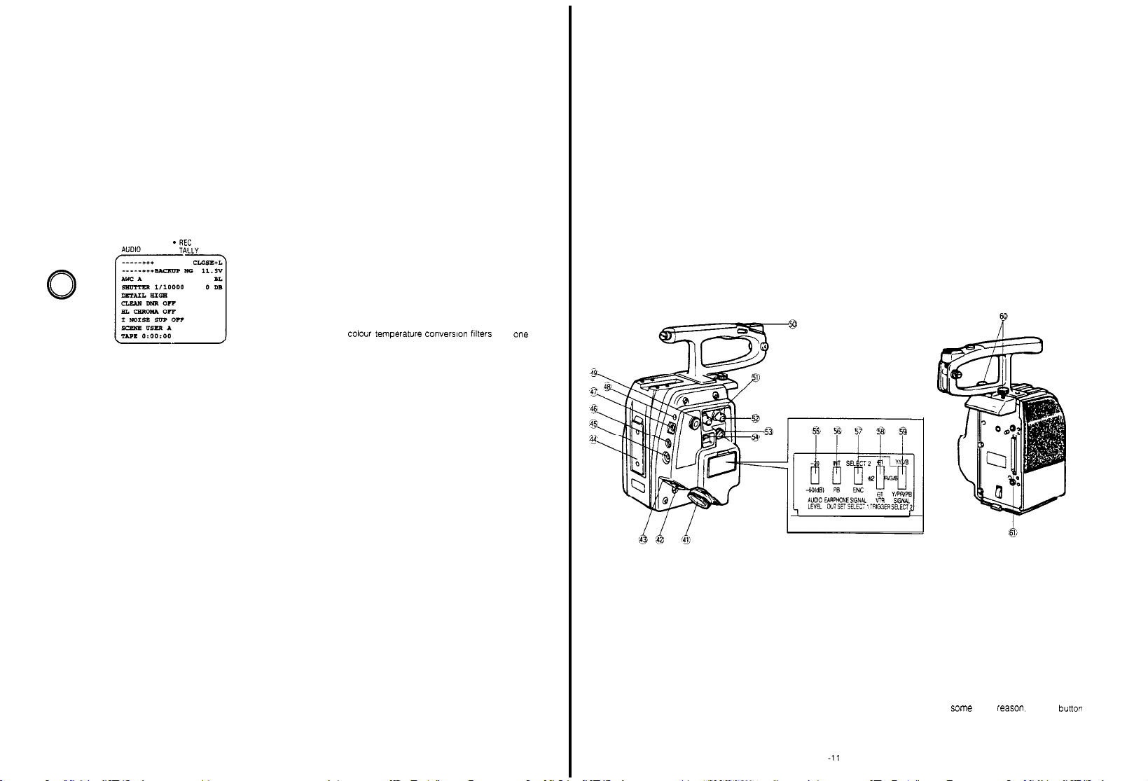
41.
VTR/RCU Connector (26-pin) (VTR/RCU)
When
using
portable
be connected
Connector is also used
studio
comprehensive
the
is automatically
the camera together
colour VTR, the
between
cable trom the
system
26-pin studio
3/4" U-vision portable
cable to
set to the RCU
WV-CA26A/14 (26P-14P
specified
the camera and VTR. T
tor
connection
Remote
Control
operation.
this connector,
operation
VTR
(14-pin)
cable)
with a Panasonic
VTR cable
When
should
ot the
Unit (RCU)
connecting
the camera
mode
his
26-pin
tor
MII portable
26
42.
Circuit
When an excessive current flows into the
to a short circuit or some
of
this circuit
VTR
WV-CA26A/26 (26P-26P
pin studio
WV-CA26U15
WV-CA26U30
WV-CA26U100
Protector (BREAKER)
(26-pin)
cable
(RCU
protector
other
protrudes to cut off the circuit.
cable)
cable)
ieason.
camera due
the red
button
- 10 -
Page 5
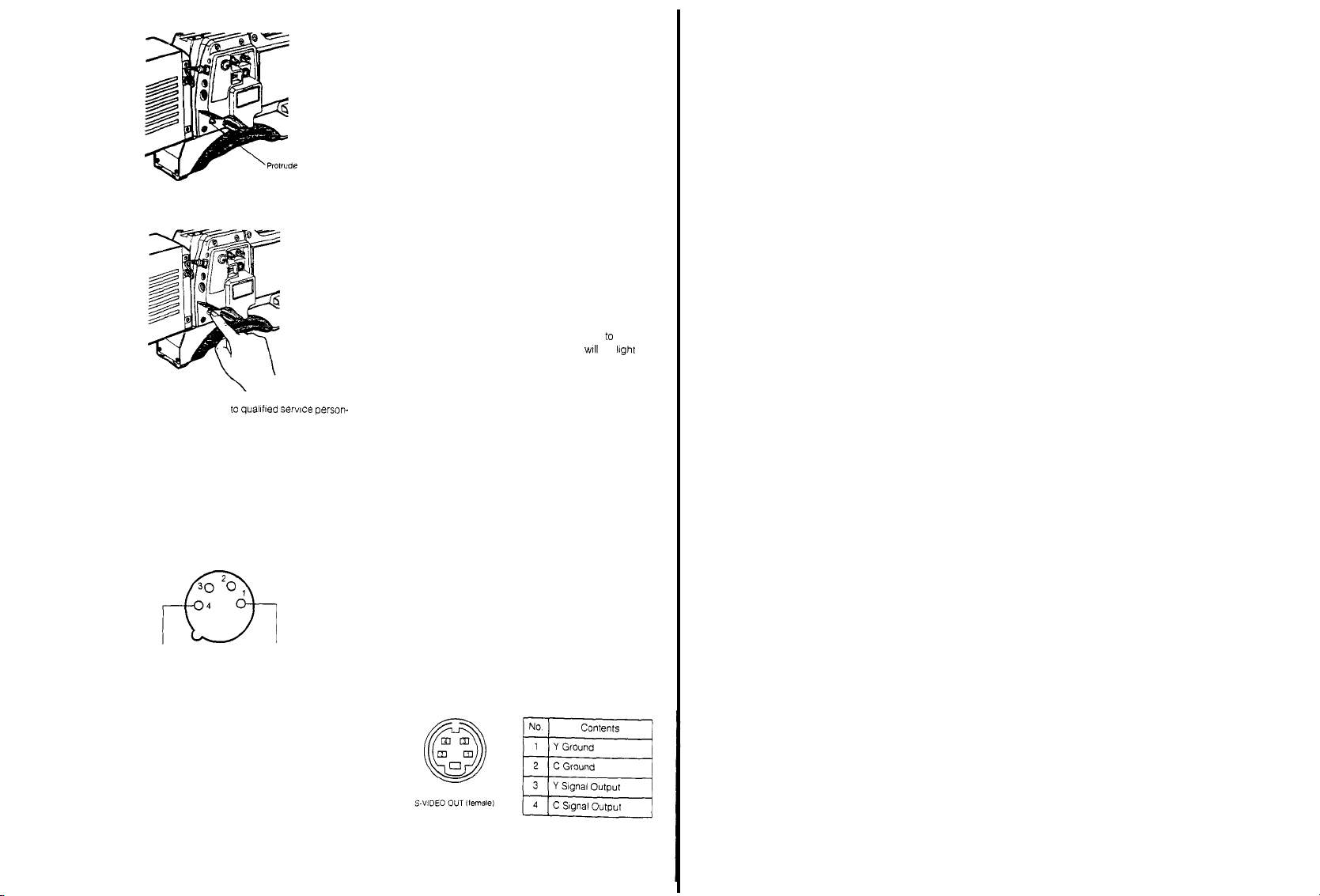
After solving
the
problem, press
to recover the circuit
CAUTION: Refer servicingo
nel to solve
the problem
43.
External
DC Input
This
connector accepts the power cable from
external
DC source
2A (a
belt
type battery or car battery for
This
connector
AC adaptor.
12V DC.
also
For
2.5A
power source is
quallfted servlce person-
Connector
(XLR,
supplying nominal
accepts the power cable from
driving
the
studio conflguration,
required
30 ,
4
+ - + 12V nominal ---- -
44.
Battery Pack Mounting Angle
Mount
the AC
era by
45. Intercom
This jack is used
era
operator
Adaptor/Charger
sliding it down along this mounting angle
Jack (M6)
(INTERCOM)
for
and
operators of
WV-PS34 on
communication between the
the RCU and
Effect Generator in a system
the red
4-pin)
button again
(EXT DC)
power of
example)
the
12V.
cam-
cam-
Special
a
-59.
VTR
54.
46.
Earphone
47.
Jack
When an earphone is connected, the sound
through
3/4" U-vision recorder. 26-pin MII
or 14-pin S-VHS portable
era, can be
(M3) (EARPHONE)
the
microphone or played back audio from a
format
VTR
connected to
monitored.
Battery Connector (BATTERY)
Connect the cord
from the
Battery Pack to this con-
picked
portable
the cam-
up
VTR
nector
48. Recording/Tally Indicator
This indicator lights
ing
mode
the
(through
person
informs
(red)
(REC TALLY)
when the VTR is set to
the VTR
Start/Stop
concerned of
the record button), and
scenes being
recorded
The
Tally Indicator also lights
full
system
operation
Unit
and
Special
In case a
reached, or if
Effects Generator
tape is not loaded or
the
servo mechanism is working improp-
when the camera is
together
with
the
Remote
the tape end
in
Control
is
erly, this indicator will start blinking to warn the operator
of
such
faults
Note: if a
portable
VTR is
not
era, the R
ecording/Tally indlcator
49.
Earphone/Intercom Level Control (LEVEL)
Use
this
control to
phone
connected to the Earphone
adjust
headset connected to the Intercom
50.
Accessory Shoe
an
an
51.
Gen-lock
The
synchronized to
black burst)
Input
Connector
colour video signal of
the
which is supplied to this
gen-lock signal is used
when
uslng
a
If the
obtained
not be
able to synchronize
Special
gen-lock signal is jittery (like
from
Caution:
connected lo the cam-
II not
light
the
volume level in
the
Jack (46) or
Jack
(45)
(BNC) (GEN-LOCK)
the camera is
automatically
gen-lock signal (composite or
connector. The
for system
reference, such
Effects Generator
VTR playback), the
camera may
properly
ear-
the
that
as
Power Selection
EXT
By using this switch the desired
nected to the camera can be
BATT/EXT
VTR/RCU: This position is used
VTR or
55.
Audio Level Selection
(AUDI0
Two
-20 dB or
-20 dB at the
56. Earphone
(EARPHONE OUT
This switch selects
jack
(46) to be
INT:
The sound
PB: The
Note: The camera has
57.
VTR
Video Output
(SIGNAL SELECT 1)
This switch selects
the
VTR/RCU
ENC:
SELECT 2: The
Note: The camera has
Switch (POWER
SELECT. BATT/
DC-VTR/RCU)
power source con-
selected
DC:
from
This position is used
the
battery
pack,
and
for power supply
external
DC source
through an AC adaptor
when power is to be
supplied
through the
the
Remote
26-pin
Control
connector from the
Unit
(RCU).
Switch
LEVEL -20/-60 dB)
audio output levels to
-60 dB. T
the
VTR
he camera has
can be
selected
been preset to
factory
Selection
Switch
SEL, INT/PB)
the
audio signal
from
the
Earphone
monitored
picked
up by the
microphone
can be
monitored
played back audio
from a
3/4" U-vision
recorder, 26-pin MII format portable VTR or 14-pin
S-VHS
portable VTR, obtained
VTR/RCU Connector
of this adaptor can be monito-
through the
tored
at the
fac:ory
been preset to the
Selection
Switch 1
the vi
deo
output si
INT
position
gnal supplied to
connector (41)
A
composite video slgnal is
VHS and
3/4" U-VISION portable VTRs.
slgnal selected
Output Selectlon Swtch
VTR/RCU Connector
(41).
been preset to
tion
at the
factory
by the
(59) is
supplied for
VTR
Video
output
from the
the
ENC post-
1 / 2
or
Video Output
When the VTR Video
to the
SELECT 2
according to
YlCiB:
The
nals
are
Connectors
VTR/RCU Connector
WG/B:
The R, G and B
R,
G and B
and from the
YBPIPR:
and
VTR/RCU Connector
Output Connectors
Unit
for
60. Camera Adaptor Holding
These
screws/knobs
tor to
the Camera head
61. 68
-pin Multi Connector
When
mountlng
pin connectors on
tor
morw
Selection Switch
Output Selectlon Switch 1 is
Position, this switch should
the VTR
type.
chrominance (C)
supplied
from
(145) of
the
(41) for S-VHS format
signals
Output Connector
VTR/RCU Connector
The
colour dlfference
luminance (Y) signal
(41) and the R, G and
(145) on the
MII
and Betacam format
Screws/Knobs.
are
used to fix
the camera
the Camera and the Camera
2 (SELECT
and
luminance
the R, G
and B
RCU and from
are
supplied from
(145) of the RCU
(41).
(R-Y & B-Y)
are
supplied
from the
Remote
VTRs.
the camera
adaptor,
engage the
set
be set
(Y)
Output
VTR.
the
signals
Control
adap-
adap-
2)
s i g-
the
B
68
.
52. Video
Output Connector (BNC)
A
composite video signal is provided
tor.
53. S-VHS Video
The
VTR or
Output Conrector
luminance (Y)
monitor
are
and
provided
(VIDEO
at
(S-VIDEO
chroma (C) signals
at
this
connector.
OUT)
this connec-
OUT)
for S-VHS
58.
VTR Compatibility
Set
thls swltch accordlng to
to
the camera
+1: For
1/2"
+2:
For
3/4" U-VISION VTRs,
S-VHS
-1: If a
VTR
VTR
pauses when
vice
versa, this
VHS
VTRs
of
Switch
(+1/+2/-1)
the VTR type connected
VTRs.
connected to the camera,
and
MII portable VTRs
other
manufacture is
the
tape should be
switch should
used, or If
be set to
running
thls posi-
the
and
tion.
Notes:
1 The
switch
has
the
factory
2
Some VTRs
nected to this
may not
camera,
this switch is changed. Please consult
er
for further
Informatlon
been preset
to the +1
operate properly
even
though the
position at
when
setting
your
con-
of
deal-
- 12 -
- 13 -
Page 6
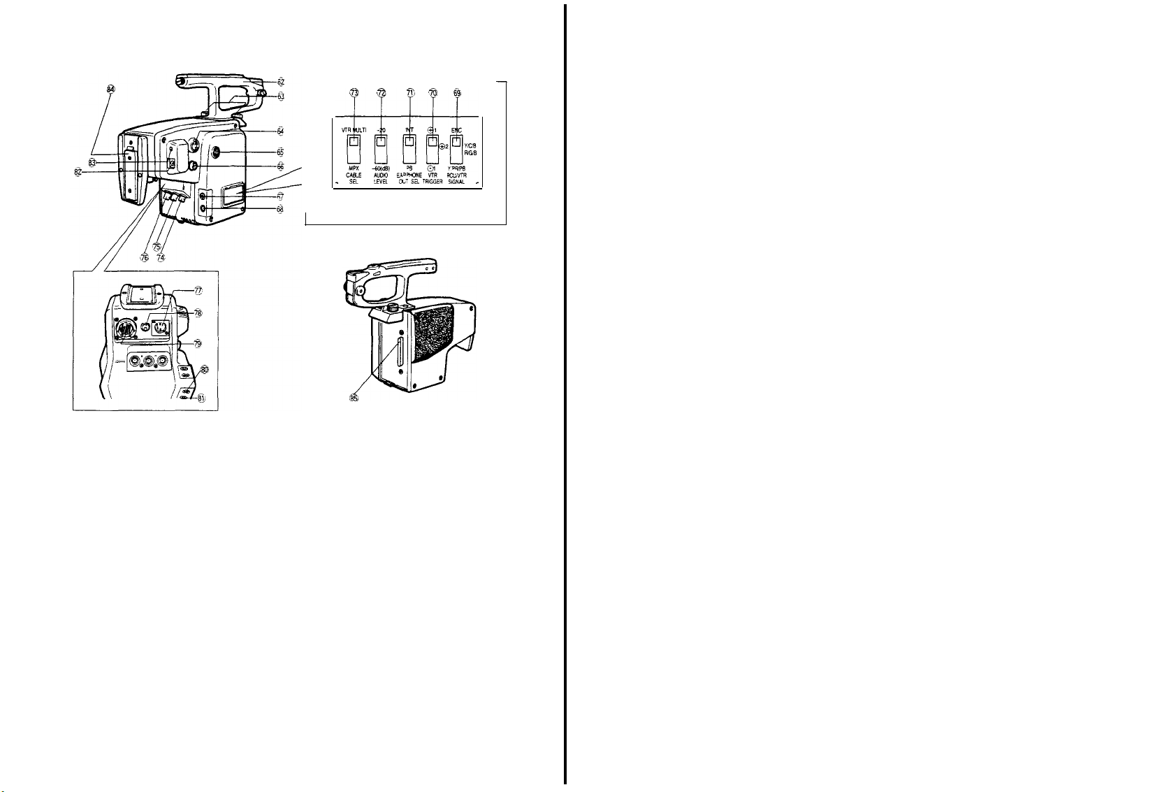
CAMERA ADAPTOR
AW-AD700BSE
62. Camera
63. Camera Adaptor
64.
65.
Handle
The camera
after loosening two
then
pressing
camera
VTR Start/Stop
This
button is
pause
in
the
same way
lens. Press
the
Tally Indicator
Light on
When the button is pressed once more,
set to the Pause mode
Recording/Tally Indicator
Intercom/Earphone Level
(INCOM
Use
thls
earphone
headset connected to the Intercom
Holding Screw/Knob
adaptor
can be removed from the camera
knobs on top of the
the
release
while pulling on rear
Button
used to change
(Recording
once to
the
vlewfinder also lights
EARPHONE)
control to
connected to the Earphone
button
(VTR) (parallel
Pause) to recording and
as the VTR
start recording. While recording,
in the
viewfinder Iights
(Recording
and
Control
freely adlust
adaptor
underneath of
of camera
adaptor
operation)
the recorder mode from
Start/Stop Button on
Tally Light
the
functlons
and the
the
recorder is
Pause), and the
will go off
volume level in
Jack
(68) or the
Jack
(67)
and
the
the
Tally
the
F
66. S-Video Output
The
lumlnance (Y)
VTR or monitor
67.
Intercom Jack (M6)
This j
era
(RCU)
68. Earphone
When
by the microphone or the
3/4" U-VISION
through the
monitored
by the Earphone Out
RCU/VTR Signal Selection Switch
69.
(RCU/VTR
This switch selects
the
Red, Green and
Remote
to the
ENC:
are
ack
is
used
operator and operators
and
Special
Jack (M3)
an
earphone is connected, the
VTR 14-pin,
Selection
SIGNAL
VTR/RCU Connector
Control Unit
R/G/B position at
The
composite
as
1/2
VHS or
Connector
for
recorder, connected
(S-VIDEO
and
chroma (C) signals
provided at this connector
(INCOM)
communication between
of the
Effect
(EARPHONE)
of
Selection Switch
ENC, Y/C/B, R/G/B. Y/PR/PB)
the video
Blue Output
(RCU).
the
Output signal
3/4"
U-
Remote
Generator
in the
sound
played back audio
camera
connector,
the audio source is enabled
Output signal
(79) on the
Matilc, is supplied
adaptor
Connectors on the
The
switch
factory
for the
OUT)
for S-VHS
Control
system.
picked
to
the camera
(71)
supplied
has
VTR, such
the cam-
Unit
from
can be
and the
been
set
Y/C/B:
The
chrominance (C)
nals
are
supplied
Connectors
R/G/B:
R.
Y/PB/PR:
and
VTR/RCU Connector
Output Connectors
MII
70.
VTR
Compatibility Switch
Set
this switch
ed to the camera.
+1:
For
+2:
For
uslng a 14-pin connector,
portable
: If a
-1
VTR
viceversa,
tion
Notes:
1 T
the
2
Some VTRs
nected to
this switch
for further
71. Earphone Out
This switch selects the audio signal
Jack
(68) to be
INT: The
monitored.
PB: The
Note: The camera has
at
72.
Audio Level Selection
(AUDI0 LEVEL -20/-60 dB)
Two
audio output levels lo
-20 dB or -60
The camera has
When
up
a
at
switch to
73. Cable
This switch is used to select either
VTR/RCU
When
Control
tlon.
using a coaxial
Note:
signal
coaxial
74. Video Output
A
composite
tor
for S-VHS format
The R. G and B
G and B
Output
The
colour difference
luminance (Y) signal
and Betacam format
according to the
1/2"
VHS
VTRs
3/4” U-vision VTRs,
VTRs
VTR of
other
pauses when the tape
this switch should
he
switch
has
factory
may not operare
this
camera,
is
changed. Please consult your dealer
mformation
Selection
monitored.
sound plcked
played back audio
the factory
dB
been preset to
using this
adaptor
the -20 dB
Selection
Switch
cable or the
using
the
and
cable
Connector
video
multi-cable in
set this
cable, set
(VP)
power
Unit (RCU),
In case of the
Video Power
and l
from the R, G and B
Connectors.
on
manufacture is
been preset to
up by the
been preset
Switch
position
single coaxial multiplex
multiplex or
are
signal is provided
uminance (Y) sig-
VTR.
stgnals
are
supplled
(R-Y & B-Y)
are
supplied
(79) and the R, G and B
the
Remote
Control
VTRs
(+1/+2/-1)
VTR which
connected to the camera
S-VHS
VTRs
used,
should
be
be set to
the +1
properly
even
though the
Switch
(INT/PB)
from
the
microphone
can be
monitored
to the INT
the
VTR
can be
-20 dB at
with WVRC700A,
(VTR
MULTIPLEX)
the
the
VTR or Remote
switch to
VTR MULTI
VP
multiplex operatlon
this
switch to MPX
Multiplex
system is
supplied uslng a slngle
(B
NC)
(VIDEO
at
Output
from the
signals
from the
Unit
is
connect-
and
and if
running
and
this posi-
posltlon at
when
setting of
Earphone
can be
position
selected:
the factory
set
this
multicable
cable.
posi-
position
multiplex
OUT)
this connec-
for
MII
this
con-
75. Gen-lock Input
The
colour
synchronized
black burst)
gen-lock
when
Caution:
obtained
not be
76.
Multiplex Signal Input Connector
Communications between
Remote
Single coaxial
composite
Intercom/audlo signal
posite signal is output
(RCU)
77.
External
This connector accepts
external
2A (a
This connector also
AC adaptor. F
12V DC, 2,5A
Cautions:
?? Use only
Class
age
fuse, located withln
necting means.
??
An external
gets the highest
the battery
source
78.
Circuit
When
some fault,
trudes to cut off
After
to reset
Caution:
nel to solve
79.
VTR/RCU Connector (26pin) (VTR/RCU)
When
portable colour VTR,
be connected
connector is also used for connection with
studio
comprehensive
the
26-pin studio
is automatlcally
operatlon
??
3/4" U-vlsion portable VTR (14-pin)
WVCA26A14 (26P-14P
MII portable VTR (26-pin)
WV-CA26A26 (26P-26P
Connector (ENC)
vi
deo signal of
to the gen-lock
whtch
is
signal
using a Special Effects Generator
If the gen-lock
Control
DC
DC
belt
type battery or car battery for
2
battery
Protector (BREAKER)
excessive current flows into
solving
the
Refer serving to qualifled serwce person-
using
cable from the
mode
supplied to this connector.
is
used for system reference, such
from VTR p
able to synchronlze properly.
Unit
(RCU) are
cable by
signal,
gen-lock
are
from the
Input Connector
source suppying nominal power of 12V.
accepts the
or
powering
power source is required.
with a
12V DC
rating.
Do
unless provided with an 8A
DC
source supplied to this connector
priority,
connector or Multicore/VTR
the red button of
the
circult power
the
problem, press
circuit
protector.
the
problem.
the camera together
the
between
system
cable to
set to the
(GEN-LOCK)
the camera is
signal (composite or
signal
is
jittery (such
layback),
the camera may
(MPX)
the camera
available
using this Connector
signal,
control
multiplexed,
Remote
(XLR,
the
not
5
the camera and
Remote
4-pin)
power
cable from
power
the
studlo configuration, a
power source with a
use
with an external stor-
inches of
the battery
if it is
selected before
the camera due
this cIrcuit
the red button
with a Panasonic
specified
VTR Cable
Control
operation.
When
this connector, the
Remote
Control
cable)
cable)
automatically
side
and the
Control
cable from
protector
Unit (RCU)
The
as when
and the
through
as the
signal
and
com-
Unit.
(EXT DC)
example)
rated
con-
DC
again
should
VTR.
T
the
26-pin
connecting
camera
Unit
(RCU)
as
a
an
an
to
pro-
his
for
-
14 -
- 15 -
Page 7
?? 26
pin Studio
Cable
(RCU
WV-CA26U15
WV-CA26U30
WV-CA26U100
80
. Lens Connector
Thi
s
connector is
zoom,
focus or
servo
81. C
ontrol
connector
This
connector is
Control Cable
92.
Battery
Connector (BATTERY)
Connect the
nector
used to
WV-CA10U25
cord
from the Battery
93. Recording/Tally Indicator
This
i
ndicator Iights
ing
mode (through the
informs the p
when the
erson
Cable)
used to
connect the lens cable
control.
connect the optional Pan/T
(red)
(REC
VTR
is set to the
VTR Start/Stop
concerned
of scenes being
Pack to this
TALLY)
Button) and
for
ilt
con-
record-
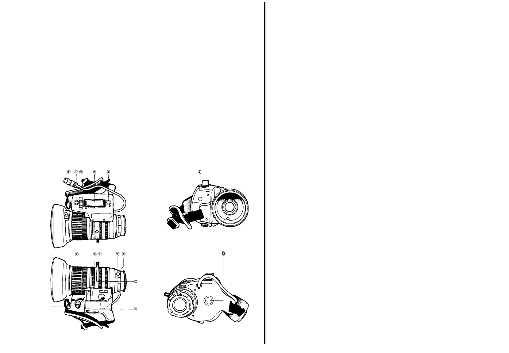
14X SERVO CONTROL ZOOM LENS AW-LZ14ST73
94-
recorded.
The
camera is in
Remote
case a tape is not loaded or the tape end is reached,
or if
the
indicator
faults.
Note:
era, the
Tally indicator also
full
system operation together
Control
Unit
and
servo mechanism
will start
blinking to
lf
a
portable
VTR is not connected to the cam-
Recording/Tally
lights when the
Special
Effects Generator i
is
working
i
warn the
mproperly, this
operator
indicator will not light.
84. Battery Pack Mounting Angle
Mount the AC
Separator
along this mounting angle
85.
66-pin
When
nectors on
Adaptor/Charger
WV-PS700 on the camera by
Multi Connector
mounting this
adaptor
the camera and
this connector
WV-PS34 or
engage
the
sliding it
66-pin
with
of
the
such
Power
down
con-
86.
Lens Cable with
n
This cable s
motor and the
The cable
(1) on the camera.
87.
Auto Iris Button (IRIS)
When
Selection
the
Iens
intensity reaching
Note: Button must be pressed
improper iris setting will result
88.
Iris Control
This switch selects the operational condition of the
lens iris:
A (Auto): The
When the camera is
together
switch should
case, the
RCU or
M
(Manual): The
by
correct lens iris
ing
89. Servo Zoom
The
zoom function
trolled by pressing this
well
as
ing
speed
applied on this
90.
Return
Video Button
When an
from a
auxiliary
while
the camera is set up for system operatlon,
signal
can be
as
long
vision
portable
14-pin
camera i
recorder is
picture
can be
pressed
91. Auto Iris Sensitivity Control (IRIS GAIN)
With setting
the A
position, adjust
trol.
92.
VTR Start/Stop
This switch is used
recorder.
VTR Start/Stop
12-pin
upplies power
should
this button is
Switch (86) is set to the M (manual) position
iris is
Selection
with
RCB
rotatlng
the Auto
Control
wide angle is possible.
can be
auxlllary signal such
Special
connector of the
as
this
set to the playback
the iris Control
Connector
to
the servo
automatlc iris
automatlcally set
control
be connected to the
pressed
the
lens
control
device.
Lens Connector
while
the
according to
for
5
lris Control
the light
seconds or
Switch (A/M)
lens
iris is
automatically controlled.
used in studto applications
the
Remote
Control
be set to the
lens
iris is remotely
lens
iris can be manually
the
lris Rlng
setting
Iris
Button (87).
(97).
can
Unit (RCU), this
‘A’ position. In this
controlled
from the
With
also
controlled
this setting, the
be set by
(Wide/Tele)
of
this
1.4f
zoom lens
control.
controlled by changing
control.
Effects Generator is supplied to the
previewed on
button is kept pressed. When a
recorder,
viewed
Remote
the
connected through the
nput
connector, or an S-VHS
as
long
Selection Swltch (88)
the iris
Galn
can be
Zooming
Furthermore, the
mode,
as
to tele as
the
pressure
as a
Ilneview signal
Control
Unit (RCU)
electronic viewfinder
the played
this
button is
by
turnlng this con-
Button (VTR)
The
to start and pause the
function of thls
Button (5) on the camera
button is i
connected
dentlcal to the
zoom
press-
con-
zoom-
3/4" U-
VTR
VTR
back
kept
to
this
After having
mode,
While recording
indicator
front of the
93.
Servo/Manual ZOom Selection
set the
pr
ess this button to
is in
in the
viewfinder
viewfinder
recorder
to the
recording
start and pause
progress, the Recording/Tally
and the
lights.
recording.
Tally Light (101) on
Switch
standby
(SERVO/MANU)
This swltch is used to select between zooming by
servo
control or
SERVO:
either side
MANU:
rotating
94. Connector
The Zoom
Control
nector. This
95.
Focus Ring
Rotating this ring willI
observing the picture in
can
easily
With the
flexible cable for the
Focus Controller, zooming
remotely
96. Zoom
By seyying
(93) to the
manually performed
times magniflcation is posslble
telephoto.
Switch
performed with
97. Iris
Ring
When the iris Control
M (manual)
adjusted by
s
98.
Flange-back Lock
The
Flange-back Adjustment Ring
by
turning this
99.
Flange-back
The
flange-back (or back
adfusted by
Knob (98)
100.
Macro Ring/Button
For
close-up shooting, rotate this ring to
area while pressing this
Servo
up shooting up to approximately
lens surface is posslble
manually
Zoom
operation is performed by
of the
Servo
Zoom
the Zoom
for
Zoom
Remote Controller included in
Kit
WV-LK35
will
allow remote
be set.
optlonal Lens
controlled.
Zoom Control (89)
operation is
performed
Ring/Lever
Remote Controller
should
be connected to
control of
change the
the
vliwfinder, correct
Control
Zoom Remote Controller
and
Ring/Lever
the
Servo/Manual
MANU
(manual) position,
through use of
When the
(93) is set to the SERVO
Servo/Manual
the
Servo
Zoom Control
Selection
positlon,
the
rotating this ring.
lens iris
Knob
knob.
Adjustment Ring
this
be
released prior to
button. After
(69) to
by
focus) of the
ring.
the WIDE
rotating this ring
rotating
should
Zoom Control
pressing
manually
(96)
lens
focus.
Kit
WV-LK35, i
focusing
Zoom
Selection Switch
zooming
this rlng/lever.
from
Zoom
position, zooming is
Switch (66) is set to the
can be
(99) can be locked
The
Flange-back Lock
adjustment
50 mm
by
the
Lens
thls con-
zooming
focus
ncluding
and
can be
can be
wide angle to
Selection
(69)
manually
lens
can be
the
macro
setting lhe
position, close-
(2”) from
the
By
13
-16 -
-17 -
Page 8
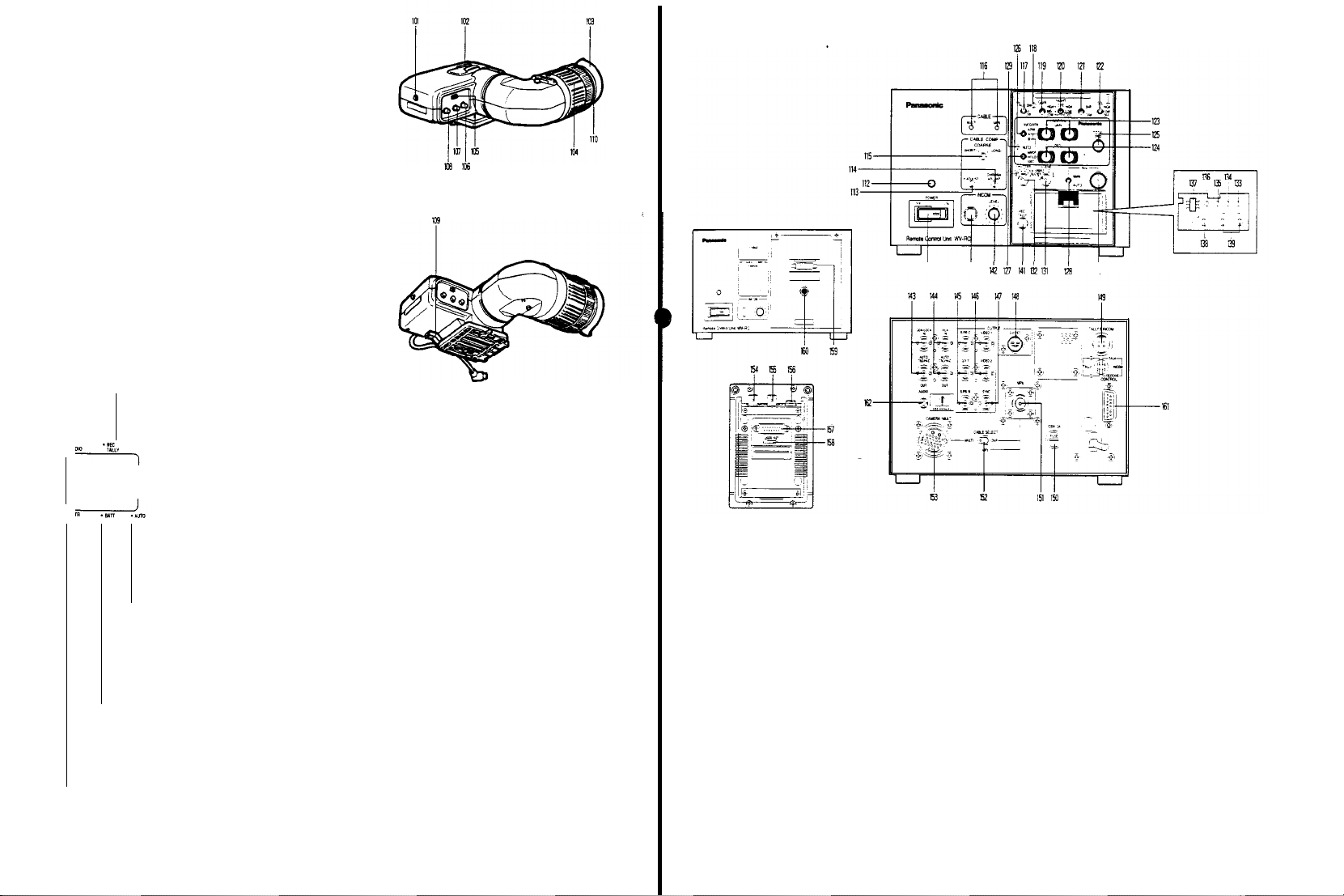
1.5” ELECTRONIC VIEWFINDER WV-VF42
101.
Tally Light
This light is lit when the Tally
set to ON
position
recording mode with the VTR Start/Stop
light i
ndicates
102.
Accesory
DO not mount a
103.
Eye Cap
The eye cap, besides blocking out
comfortable viewing
may be flipped
104. Diopter Adjustment Ring
Rotate this rlng
Note:
Loosen the Lock Ring
ment
105. Tally ON/OFF Switch
This swtich turns
on front of
and the
that
Shoe
light
open if thls is desired.
for
ON/OFF the Tally
fhe viewfinder
ON/OFF switch (105) is
VTR
has
been
recording in in progress.
source
(110)
before this adlust-
Light
stray light, offers
picture.
of the monitor
optimum diopter setting
(TALLY ON/OFF)
set to the
Switch.
The cap
(101)
This
located
REMOTE
CONTROL UNIT WV-RC7OOA
YO
$1
!k
LED Indicators in
- Recording/Tally
r
-Auto
-
Battery
When
be
cient power to
after
-
Shutter/High Gain
The
Indicator lights
of
MID or
Selection Switch (29)
the
Electronic Viewfinder
Indicator
This indicator lights
set to the
recording
the VTR
Start/Stop Switch.
using
the camera
recorder or 1/2"
through
the use of the
camera
connector, MII
26-pin connector. If
not loaded,
the tape
if
the
servo mechanism is not working
properly, this Indicator blinks to warn
the
camera
Nota: If a portable VTR is
This Indicator blinks while
balance or black balance is
automatically
when the
i
automatlc settlng
and/or
Warning
this lndicator blinks, the battery should
replaced.
the i
Indicator
HIGH
has
operator.
ed to the camera, the
Tally
Indlcator will
Warning
Indicator
white or
mproperly.
black balance.
Indicator
The battery
the camera for a few minutes
ndicator starts blinking.
(GreenlRed)
red to
indicate high gain selection
been selected with
(Red)
when the
mode by
with a 3/4" U-vision
S-VHS portable VTR,
VTR’s 14-pin
portable
the
vldeo
end
not
(Green)
set.
This indicator lights
black balance is set
In
this
case,
procedure for
(Amber)
will only supply suffi-
the
VTR is
pressing
When
VTR’s
tape is
is reached
not connect-
Recording/
Iight.
the
white
being
carry out
white
High/Gain
the
When the
shutter isturned on, this Iights in green.
indicator Iights yellow to indicate
the
high gain selection
selected.
And
also this indicator
shutter on
or
106. Brightness
107.
108.
109.
110.
when the
been selected
Selectlon
Switch (27).
Turn
this
control
of
the
picture
Contrast
Control (CONTRAST)
Turn
this
control
the
picture in
Peaking Control (PEAKING)
When
shooting under
control
clockwise will facilitate
ment.
Viewfinder Slide Stopper
When
removing
release
the vi
viewfinder to
pulling this stopper
Lock Ring
After
completing
ring
high gain selection
by the
Control
(BRIGHT)
clockwise to increase
in the
wiewfinder.
clockwise to increase
the
viewfinder
low light
the view
ewfinder Lock lever
the
right
(as
the
diopter adjustment, tighten this
the
of MID or
lights
Colour Bar/Night Eye/Camera
finder
viewed
shutter on
HIGH
yellow to indIcate
the
conditions, turning this
easy
focusing adjust-
from the camera,
and
from
has
of NE has
brightness
the
contrast
then slide
the
front)
This
when
been
the
fist
the
while
The
illustration
111.
Power
Switch (POWER,
of
Thls swltch turns on
Control Unit (RCU)
112.
Power
Indicator
This switch Iights
113.
Luminance Gain
This
control
nance
signal level
eras ina system.
set the Cable Length
the
correct positi
114.
Chroma Gain
This
control
signal level
cameras in a system.
ing set the Cable Length
to
the
correct position
red
Fine Control (Y
allows
for
Adjust this
on
Fine Control
allows
for
for
matching
and off the
whenever
for
matching
Adjust this
of the front panel
ON/OFF)
power of
the
the
unit
is
operating.
ADJUST)
fine adjustment
control
Compensation
(CHROMA ADJUST)
fine adjustment
the
Compensation Switch (115)
of the
the
levels
of
only after having
Switch (115)
of the
chroma levels
control only
all
of
after hav-
Remote
lumi-
cam-
chroma
all
the
shown above
to
has
been stuck
115. Cable Length Compensation Switch
(CABLE/COMP)
This swltch is
lengths
camera and
1
2
3
4
This
cable
camera and
1. U
2. Use for cable
3 Not
4 Not
116.
Cable Indicator (CABLE,
Thls indicator
Selection
the operation seat.
used to compensate for
used with
the
26-pin multi-cable between
Remote
Control
Use for cable
Use for cable l
Use for cable
Use for cable length of
switch is also used to compensate for
lengths used with
Remote
se for cable length of
avallable
avallable
shows the
Switch (152) on the
Unit (RCU)
length
of
less than
ength of 75-150m (225-450
length
of
150-230m (450-690 ft)
230-300m (690-900 ft)
the
coaxial
Control
length of 150-300m (450-990 ft)
cable
Unit (RCU)
less than 50m
MULTI/MPX)
setting position
rear
panel
extensive
75m (225
extensive
between
(450
of the Cable
ft
cable
the
ft)
)
the
ft)
- 18 -
-19 -
Page 9

117. Remote
118. Remote Control Box Indicator (ON/OFF)
This indicator lights when control data is communicat-
119.
120. Night
121.
122.
123. Red and
Control
(RCB)
When
era
without using the Remote Control Box, set this
switch to ON position. When the RCB is installed in the
RCU, this switch can not operate.
ed between the camera and the Remote Control Unit
(RCU)
or
High Gain Selection switch
The gain up level
The Ievet
Sub
Menu with
(NIGHT
HIGH:
position
LOW:
Gain-up level
position
OFF:
Selection
Note: When
tion,
not
Colour Bar/Camara
In a system
selection between
mode.
BAR: A
Output
Unit
CAM: The actual
lens is displayed
Detail Level Selection Switch
(DTL, LEVEL-HIGH/LOW/OFF)
The
detail/aperture level
in
switch
position while observing
(PAINTlNG, R GAINB
These controls
balance.
These controls only
Selection Switch (126) is set
PAINTING in No. 2 Sub
Box (RCB) Operation
co
nnecting the Remote Control Box to the cam-
Remote Control Box (RCB).
can be
of
HIGH,
the
Eye
Selection Switch
EYE, HIGH/LOW/OFF)
Gain-up level of +36
Gain-up level
Switch
this switch is
the High
work.
configuration, this switch is used for signal
colour
bar
Connector (146) on the
(RCU)
three
steps. Set
Elua Gain Controls
are
(GAIN. HlGH/MID/LOW)
selected by
MID and LOW can be set by
combination shown below
dB can be
of
+30 dB
can be set by the High
(119).
set the HIGH or LOW
Gain
Selection Switch (119)
Selection Switch
camera mode and
signal
is
provlded
picture,
as
picked
can be selected by
this swltch to
the
sharpness
GAIN)
used to manually adjust the whlte
work when the
to
Menu
is set to the
this
can be
from the Video
Remote
up through the
of the
Whlte
the A or B
Switch
switch
obtalned at this
obtained at this
does
(BAR/CAM)
colour
Control
this
the desired
picture.
Balance
position
ON
Gain
posi-
bar
the
and
~
turn
the controls clockwise to
blue signal levels and
these
levels.
Note:
As
these controls employ Digital Processing,
the Red and
discrete steps
124. Red and
125. Total Pedestal
126. White Balance Selection Switch
127. Auto
This switch Sets
HOLD:
2
ABC:
Blue
The black
balance
trols
when fine
the
ON. Turn these controls clockwise to
blue
red and
decrease
the
Note: As
these controls employ
Processing, these level will
crete steps
This
control can
slgnal (IumlnanCe)
WO or
between
control
clockwlse to increase
counterclockwise to decrease
Note: As
this
this level will
(AUTO/ATW, ATW/A/B)
This switch
as
ATW:
A:
B: Simllar to A, but
Note: Two
(AWC/HOLD/ABC)
automatically
AWC:
is
follows:
The
white
Iy
The
White
pressing
(127) upwards. The
white
ent
lighting conditions such
door,
may
B.
White/Auto Black
This position is used for setting
ance when the
(126) is set to the A
adjustment is required
AWC B NG" is
"
when the Auto
In
this posltlon,
at
the AWC or ABC
set
if
so desired, for at
Thls posltlon IS used for senlng
ance when the
(126) is set to
counterclockwise to
Blue signal levels will
Pedestal
Level Controls
can be set
PAINTING in No.2 Sub
pedestal
levels,
and
levels
Level
Control (TOTAL PED)
adlust
the pedestal
for
matchlng tha
more cameras in a system.
control
used to select
balance can be
Balance can be set
the Auto
balance
be
the
as
follows:
the pedestal
the
employs
be
the
stored in
Warning indicator
the
the
changed in discrete
the
White/Auto Black
setting is stored in memory
setting is stored in memory B
setting,
the
two memories,
Set Switch
white
balance and black balance
White
Balance Selection Switch
or
B
position. White
when "AWC A NG"
displayed
in the
the
white
position
least
one year
White Balance Selectlon Swltch
A or B
positlon
in
crease the
red and
decrease
be
changed in
(PED,
manually
by
these con-
Menu
is set
i
ncrease
CounterclockwIse to
the
Digital
be
changed in
level of
the
black
ievel
Turn this
level,
level.
Digital Processing.
steps.
white
balance
adjusted automatical-
automatically
Set Swltch
one
each for dlffer-
as
indoor
and
A and
the
white
balance
viewfinder or
(129) on
and black balances
can be
Iights
held flxed,
the black bal-
R/B)
dls-
vtdeo
and
modes
by
out-
bal-
or
the
A.
Note: The
smear
objects
133. Down
switch (DOWN)
This switch is used to decrease the
Black
balance
adjustment
is
required
displayed in
is
warning
to
(RCU) Iights.
Note:
and on the
128.
Lens
This switch is used to
servo
AUTO: The iris
cally
Note: Be
on
MAN: The iris
desired
129. Auto Warning
This indicator blinks while
balance is
white
the
This indicator Iights
improperly. In this
set
setting
130.
Lens
The iris
trolled
Selection
‘AUTO IRIS' on Sub
‘ADJ
this level is avalilable
Scene Selection Switch
131.
This switch is used to select
conditions, depending on scene conditions, to obtain
the best
Refer to
132.
Electronic Shutter Speed
(SHUTTER
This switch is operative only
the
electronic shutter is connected with
Control
When
speeds
will appear
OFF:
Set
normally with
120/500/1000:
these
The
S/S:
from 50 0 250 4 Hz at
SYNCRO in No 1 Sub
ELC:
the
the
in
While
performed, the
that the
and will
Iris Selection Switch (IRIS,
control
the
and black balances
procedure for
Iris Control (IRIS)
level
by
Switch (128) is set to the MAN
ON' in
picture possible.
page 60 for
Unit.
fast-moving objects
typically found in conventional
The
luminance with
viewfinder or
dicator
(129) on the
the black balance
picture will
monitor screen. This flashing indicates
adjustment
cease
sure to
zoom lens
level
being automatically
turning this
the Auto
0FF/120,500,1000,
blurred.
this switch to this position
shutter speed
ELC posistion makes
is
once the
set the
zoom lens
as
level of
the
set the iris Control
to the AUTO
level of
the
by
using
Indicator
(AUTO)
the
when the
case,
whtte and/or
of the
zoom lens
control when the
Menu/User
Iris mode,
(SCENE USER
details
are shot at the
standard shutter speeds
Choose
the suitable shutter speed
can be
the
when ‘ABC NG’
when the Auto
Remote
Control
adjustment is being
flash in the
currently being performed
adjustment
lens
follows.
lens
is
lens
the
Lens iris
white
set, it
have been correctly
white or
carry out
can be
the
the most
Selection Switch
S/S,
when a camera
this position
Menu
the
shutter
vlewfinder
is
completed.
M/A/AUTO)
iris of the auto-iris
controlled automati-
Selection Switch
position
is
controlled to
Control (130).
balance or black
goes out
black balance is
the
automatic
black balance
manually con-
Lens
Iris
position.
Set
Menu is
set
fine adjustment of
SET,
1,2,3)
suitable
camera
ELC)
featurlng
the
Remote
slow shutter
cameras
when
recording
continual changed
by
using
electric
control for
Unit
the
once
set
to
they
from
the
item p
menu
134. Up Switch (UP)
This swltch is used to increase the
desired
User
Set
135. Item Switch (ITEM)
This switch is
menus.
136. Page Switch (PAGE)
This switch
from the four
137.
User
Set ENC/VF Selection Switch
(ENC/VF, OFF/ON)
This switch selects Encoder output or
white) output
whether the
1
Switch set to
The
2 Switch set to
The
3.
Switch
User
played
138. Horizontal
horizontal phase of the camera signal
The
adjusted
the Gen-lock
139.
Subcarrier
(SC PHASE COARSE/FINE)
These
subcarrier
nal
phase with
Input
Connector (143) in a system
The COARSE
from 0ºto 360º in 90º steps,
allows
for
90º
140.
Intercom Jack
This jack is used
camera
operator in
Effects
141. Tally Indicator (REC/TALLY)
When the
junction
Indicator
on
the
that recording is in progress.
may be appeared
used to choosa eslred
ointed out by
item pointed out by
to match the
controls allow
operator
Generator
with a Special
Remote Control Unit (RCU) will light to indicate
the cursor
menu.
used to
choose the item in
is used to choose the desired set-up menu
menus.
from the
User
User
User
set to
Set
on the
Phase
Phase
that of the
continuous fine adjustment over
a system
Remote
Inside the viewfinder
Video Output
Set
Function is available
position ENC/OFF
Set
function is not available
position ENC/ON:
Set
function is available.
position VF/ON:
functionisavailable
monitor
and EVF
Control for Gen-lock (H PHASE)
horizontal
Input
Connector (143).
Coarse
for
adjustment of
phase from 0º to 360º, to match the
burst signal at
control adjusts the subcarrier phase
(INTERCOM)
for
communications between
and
Remote
configuration with
Control
Effects
with
the
high light
set value of the
when in
the
User
set value of the
the cursor when in the
the set-up
slgnal
EVF
(black
subcarrler
Connector and
and the
phase of the signal at
and Fine
Controls
the camera
configuration
while
the FINE control
Control
Unit (RCU) is used in con-
Generator,
as
well
as
and
as
follows
menu is dis-
can be
the Gen-lock
phase
a
range of
the
Unit
(RCU)
a
Special
the
Tally
this indicator
Set
at
sig-
’
- 21 -
Page 10
Note: When using
the Remote
start/stop function is not avallable.
143. Intercom Level
Use this control
set
connected to
143. Gen-lock
(GEN-LOCK
These connectors receive the gen-lock signal (black
burst or composite)
for
system
When connecting a
to
this connector,
nated
with
Caution: As
with
Connector (155), do not
both of these connectors
144. Auxiliary Input
(AUX
I N-AUTO / 75 Ohm.
These connectors
Special
Effects Generator. Two connectors are
ed for
bridging or looping application
When connecting a coaxial
to this
connector,
nated
with
145. Red,
Green
(OUTPUT-R/PR/C,
Signals supplied
by the
RCU/VTR Signal Selection Switch
Camera Adaptor.
RCU/VTR Selection
Note: The
the Camera Adaptor has
position
146. Video Output Connectors
(OUTPUT-VIDEO 1, VIDEO 2)
These connectors supply a
a Special
Note:
This
Monitor
Control
147. Sync Output Connector (SYNC
This
Connector
signal
to the Sync Input of an RGB
Monitor
tor
148. S-Video Output Connector (S-VIDEO)
This
connector
RCU/VTR Signal Selection Switch
adaptor is set to the
the
Remote
Control
control
to
adjust
the Intercom Jack
Input
Connectors
IN AUTO
from the
reference.
coaxial
this
75 ohms.
this
connector is in
the
Remote
Connectors
receive
this
75 ohms
and
Blue
G/Y/Y, B/PB/B)
from these connectors are
Refer to
Switch.
RCU/VTR Signal Selection Switch
at the
factory
Effects Generator, a Video
connector is in
Output Connector (154) on the
Box (RCB).
supplies a negative 4Vp-p/75
synchronization.
outputs
Y/C/B Position
Control Box
Unit (RCU),
(INTERCOM LEVEL)
the
volume level in
(BNC)
75 O h m. / H i - Z OUT)
Special
cable
connector is
Control
Hi-Z
connector is
Output Connectors
with
automatically termi-
parallel connection
Box
input
gen-lock
simultaneously
OUT)
the
lineview signal from a
cable
with
automatically termi-
page 47 tor
been
composite video signal
Monitor or
parallel
connection
OUTPUT)
the
Y/C signal
(69) on the camera
(RCB) in
the
recording
the
(140)
Ettects Generator
Gen-lock Input
set to the
head-
(black
BNC connector
signals to
provid-
BNC connector
selected
(69) on the
setting
the
(69)
ENC
to
a VTR
with
the
Remote
sync
Colour
Video
when the
149. Tally
and
Intercom lnput Connector
(TALLY & INTERCOM)
Connect a 4-pin
Tatty and
Generator
150.
Fuse
151.
Multiplex
This
connector is connected to the
on
Connector ot the camera
signa1
equal)
Note: When
Selection Switch
152. Cable
(CABLE SELECT,
Set
this switch
ing to the control cable
MULTI: Select this position
(Multi
MPX:
Caution: Do
cable together
153.
Multi-cable
This
connector is connected
Connector (41) by
Note: Be
to
154. Monitor Output Connector of the
Box (RCB)
As
this
OUTPUT-VIDEO 2 Connector (146). do
signal slmultaneously
155. Gen-lock Input Connector of Remote Control Box
This
connector is
the
Remote
Control
156. Remote Control
This
connector is
Box from the
by
using
CA10B25/WV-CA10B50)
The
maximum
(300 tt)
Refer
to the
cable
Intercom Output
(250V
1,25A)
Connector (MPX)
using this
(152) to MPX
Selection
Switch
MULTI/MPX)
to the MULTI or MPX
cable) is
Select this position
2V) is
the
connector is in
Box
the
used
used to
control the camera
not
use the
Connector (CAMERA)
using
sure to
Set the Cable
MULTI position.
from both connectors.
used
Control Box when
extended trom the
Unit Extension
used
Remote
Control Unit or from the camera
optional
RCB cable
cable
length
following table
between this
connector. set the Cable
used.
to control the camera
the
to
to
connector and the
ot the Speclal Effects
with coaxial
when the
when the
multi-cable
with
multi-cable (26-pin)
Selection Switch
parallel connection with
input
the gen-lock
Remote
Connector
extend
the
(WV-CA10B02/WV-
for the
Multiplex
cable
(5C-2V or
position
position accord-
26-pin
coaxial
cable
and the
the
VTR/RCU
Remote
Control
not
output the
signal
using
the
Remote
Control
Remote
Control
extension is 100m
coaxial
Unit
cable
(5C-
(152)
the
to
157.
Remote
Control Unit Connector
This
connector is
Remote Control
Control Unit.
158. Not
used
159.
Remote
This
connector is connected directly
Control
BOX.
160. Remote
This is
connected to the
Extension
by
using
Refer to Item
161. Control Connector (CONTROL)
This
connector is connected
tor ot the
cable
(15-pin)
DEFROSTER
WIPER
Lens Control Voltage
used
for
directly connecting with
Box Connector (159) on the
Control
Box
Connector
Unit
Connector (157) on the
Control Box
Connector (156) on the
the
optional
156 tor more
pan/tilt unit
Extension
cable.
or
lens
|
2 5V
|
2 5V 0
details.
control by
Remote
Remote
with
the control
|
with
the
Remote
Connector
Control
Control
using
the
0
the
Remote
Remote
Control
Unit
Box
connec-
multi-
|
162.
Audio
Output
Jack
(AUDI0
By
setting the Audio Level Selection Switch
Camera Adaptor
tion,
the
Note: In case of
set the
Camera Adaptor
position.
the Camera Adaptor
on
position
vated
AW-AD700BSE to
audio
output is
Multiplex
Audio Level Selection Switch
Me
Switch
the MOD board
for the
OUT)
available.
or VP
AW-AD700BSE
1 on the
AW-AD700BSE
inside this unlt to
Audio
Output
the
Multiplex operation,
Audio
function to
REMOTE CONTROL UNIT RACK
MOUNT FRAME WV-Q70
165.
Rack-mounting Spacer
This is used
Unit in a rack
166.
Rack-mounting Angles
These
ing two Remote
167.
Remote
These
together.
when
mounting a single Remote
two Rack-mounting Angles
Control
Units side
Control Unit
bars
are
used
Joining
to
join two Remote
by
Bar
are
side in a rack
of the
-20 dB posi-
of the
to the -20
Board in
side
and
Switch
the AUDI0
be
acti-
Control
used for mount-
Control
Units
dB
2
- 22 -
Note: As the
video level is changed
cable
lengths, under certain conditions it
out of the
specification
for the
by
using various
AW-F575E.
may be
Note: The
be 2 kohms or
impedance
for the control
less
voltage should
- 23 -
Page 11
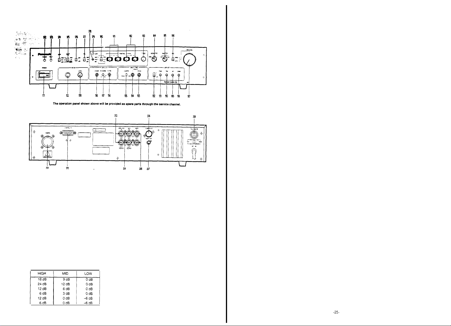
REMOTE CONTROL
171.
Power
Switch (POWER
This switch turns on
Control
Unit (RCU)
172.
Power
Indicator
This
switch lights red
173.
Tally
Indicator
When
Effects
the
Generator
174. High
The
The
Sub
selection
gain-up level
level
Menu with
(TALLY)
this unit is
Gain
used in
Generator, this indicator will
of
this unit
Selection Switch (GAIN,
can be selected.
of
HIGH,
MID and LOW can be set by the
the
combination
UNIT
WV-RC550
ON/OFF)
and off the
whenever
power of
the
unit is operating.
conjunction with a Special
light to
from a Special Effects
HIGH / MID / LOW)
shown
below
the
Remote
indicate
175. Night
176.
Eye
Selection Switch
(NIGHT EYE, HIGH/LOW/OFF)
HIGH: Gain-up level
position.
LOW:
Gain-up level
position
OFF: Gain-up level
Selection
Note: When
Colour Bar/Camera
In a
selection between
mode
BAR: A
CAM: The actual camera
Swttch
this
position
Selection Switch
system
Output
through
swttch is set to the HIGH or LOW
the
gain-level setting
configuration, this
camera
colour
bar
Connector (205) of this unit
the lens, is displayed
of
+36 dB
can be
obtained at this
of
+30 dB
can be
obtained at this
can be set by the
(174) is
Selection
slgnal is provided
by the
not available
Switch (BAR/CAM)
Swttch is
used
mode
and
from the
picture,
as
High Gain
High Gain
for
signal
colour
bar
Video
picked up
177. Detail Level
(DTL,
The
switch in
position while observing
178. Auto
(AWC/HOLD/ABC)
This
switch
automatically
AWC:
ance when the
set to the A or B
Selection
is required
this unit lights.
HOLD: In
set at the AWC or ABC
if so
ABC:
ance
(180) is
ment is
on this unit lights
Notes:
1.
While
formed, the
screen.
ment is currently being
once the
2. If the
position,
formed correctly
179. Auto
This indicator
balance is
the
white
This indicator
set
improperly
setting
180.
White
(AUTO/ATW, ATW/A/B)
This switch is used to select
as
follows.
ATW:
ly
A: The
pressing
(178) upwards The
B:
Similar to A.
Note: When
and PAINTING in No 2 Sub Menu or
has
ance or red and
adjusted fine
(181) or Red and
(182).
Selection Switch
LEVEL-HIGH/LOW/OFF)
detail/aperture level
three
steps. Set
White/Auto
This position is used
This position is used
Warning
procedure for
Balance
The
Black Set Switch
sets
the
white
as
follows.
White
Swttch
when the Auto
this position,
desired,
for at
even if the White
set to
any position Black
required
when the Auto
the black balance
picture
This flashing indicates
adjustment is completed.
Lens Iris Selection
Auto
Black
Indicator (AUTO)
blinks
while
being automatically
and
black
balances
lights when the
In this case,
white and/or black
Selection
white
balance can be
white
balance can be set
the Auto
but the
this
switch is set to the A or B
been
set to the ON
by the Red and
can be selected by
this
switch to the
the sharpness of the
balance and black balance
for
setting
Balance
position
(180) White
the
position
least
for
Balance
will
performed and
Balance may be not
the
Switch
White/Auto
setting is stored in
setting is stored in memory
blue
pedestal
Blue
the
Salection
of the
White
balance
adjustment
Warning Indicator on
white
and black balances
can be
one
setting
adjustment is
flashon the
Swttch is set to MAN
white
set. It goes
have been
white or black
carry out
the
position,
Pedestal
held
year.
the black bal-
Selection
balance
Warning Indicator
being
that the
balance or
correctly set.
balance
the
balance
white
balance
adjusted automatical-
automatically
Black Set Swttch
memory A.
User menu
the
levels
Blue Gain Controls
Level Controls
desired
picture
white
bal-
Swttch
Balance
fixed,
Switch
adjust-
monitor
adjust-
will cease
black
out
once
automatic
mode
B
position
white
bal-
can be
per-
per-
by
this
When
this switch is set to the
ance
can be
continuously adjusted automatically
181. Red and
is
182. Red and
183. Total Pedestal
184.
is
Blue Gain Controls
These controls
level of white
These controls only
Selection
PAINTING in No 2
Turn
blue signal levels,
these levels
Note: As
The fine
ually
These
Menu is set to ON mode
Turn
blue
decrease
Note: As
This
control can
signal (luminance)
between two or
control
counterclockwise to decrease
Note: As
Scene File Selection
(SCENE FILE, USER A/B/1/2/3)
This switch is
conditions
tute
1:
Studio
2: ENG Mode
3: Low
USER:
are
balance.
Switch
these controls ctockwise
these controls
the Red and
discrete steps
Blue
Pedestal
adjustment of black
by these
controls
controls only
these controls clockwise to increase
pedestal
levels,
the
levels
this
control employs
these levels
level may
This
condition.
Note:
This position is suttable
rescent, halogen or outdoor lightning
Note: The
This
shooting
desired level by the user
are
Level
adjust
for
more cameras in a system.
clockwise to increase the
this
control
be
changed in
used to
for
various scenes to obtain
Mode
position is suitable for shooting in
This level is adjusted
2000 lux 3200ºK at
shooting condition
the
Main menu
Light Mode
position is suitable for low ilumination level
The camera
ATW
position, white bal-
(R
GAIN/B
used to manually adjust
work when the
(180) is
Set to
Sub Menu is
and
Biue signal levels will
set to the ON mode.
to
counterclockwise to decrease
employ
Level Controls
balance can be set
work when PAINTING in No 2 Sub
and
counterclockwise to
changed in discrete steps
Control
the pedestal
matching
the
employs Digital Processing, this
the
Switch
select
the
F8
for
conditions
GAIN)
the
White
Balance
A/B position
increase the
(T.
PED)
the black
pedestal
level
step.
most suitable
under the
shooting
can be selected
can be set to the
red and
Digital Processmg,
be
changed in
(PED,
R/B)
the red and
Digital processing,
level
of the
Turn this
level,
camera
the
best pic-
normal
condition
under
fine
and
man-
video
levels
and
of
fluo-
on
- 24 -
Page 12
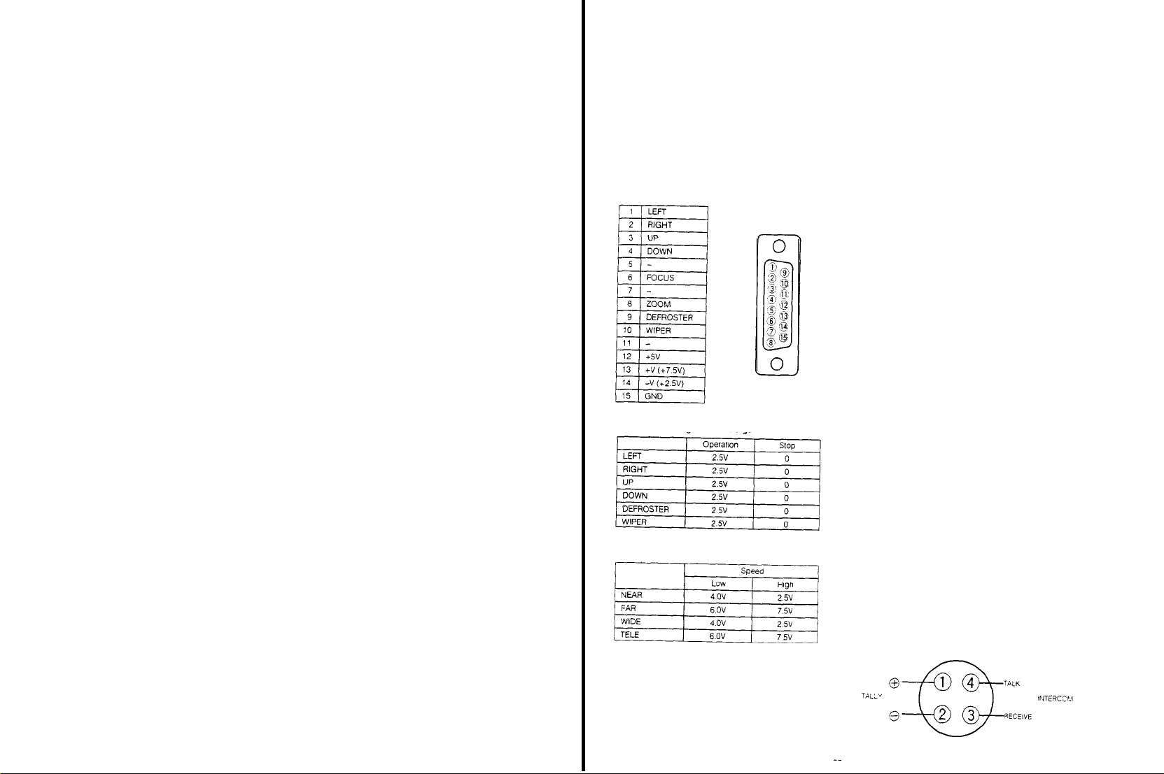
185. Electronic Shutter Selection Switch
( O F F / 120 / 500 / 1000 / S S / E L C)
This switch is operative
the electronic shutter function is
unit
OFF: set this switch to this position when recording
normally with
120/500/1000: Choose
these
S/S: Shutter speed
position using
horizontal
switch is
ELC:
The
the
luminance with
Notes:
1. The
smear
objects
2. When the
been
set to the AUTO,
Electronic Light
made by
ously
186. Lens
Iris Selection Switch (IRIS,
AUTO: When the
lens
has
level of
When AUTO IRIS in No.1 Sub
to ADJ
means of
MANU:
The
by
turning the Iris Level
187.
Iris
Level
Control (IRIS
This
control is
level, which
trolled
fine by
Selection Switch
AUTO IRIS in No.1 Sub
position
188.
Down Switch (DOWN)
This Switch is used
item pointed out
189.
Up
Switch (UP)
This switch is used to lncrease
desired item pointed
190.
Item Switch
This switch is used to choose
menus
191. Page
Switch (PAGE)
This swltch is
from
the avallable
only
when a
camera featuring
connected
standard
shutter speeds
the
suitable
when recording high speed action.
can be
SYNCRO in No 1 Sub
bar
noise will
set to this
ELC position
makes the
the shutter
may be appeared
Lens Iris Selection
Control
the Iris Level
adjusted to
be
position
the fine adjustment
(ELC)
Control (187)
shutter
reduced when this
electric control
with
Switch (186) has
and
MANU/AUTO)
iris
Control Selection Switch of the
been
set to the A (Auto)
the
lens is controlled automatically
ON.
the
iris level
the
Iris Level
iris level
of the
Menu
can be
Control (167)
lens is controlled manually
Control (167)
LEVEL)
used to adjust
had
using this
(166) is set to
by the cursor
the
been automatically
control when the
the
Menu is
to
decrease
the set value of
in a menu
out
the set
by the cursor
lens iris level.
set, can be
AUTO
set to the ADJ
(ITEM)
the
item in
used to select the desired set-up menu
menus
speed from
the
desired
Menu
so that
the
high light l ght
lens iris can
simultane-
position,
the iris
has
been
adjusted fine
The
Lens Iris
position and
value of the
in a menu
the set-up
with this
for
of
be
set
by
iris
con-
ON
the
192.
User
Set Switch
This switch selects Encoder output or
white) output from
whether the User
OFF: Switch
Setup function is
1: Switch set to
User
Menu is displayed on
2:
Switch
User
Menu is displayed on
193. Chroma
This
control
signal level for matching
cameras in a
Adjust this Control only after having
Length
Luminance Gain Fine
tion
( OFF / 1 / 2 )
the
Video
Set
set to
position
position #1
Set
function is available
set to
position #2:
Set
function is
Gain
Fine Control (ADJUST CHROMA)
allows for fine adjustment
system
Compensation
Output Connector and
Function is
avallable as
OFF
not
available
and the
the EVF
avallable and the
the
monitor
and the EVF
the
chroma levels
Switch (195) and
Control (194) to the
set the Cable
EVF (black and
follows:
User
User
of the
chroma
of
all the
correct posi-
194. Luminance Gain Fine Control (ADJUST Y)
This
control
allows
for fine
adjustment
nance
signal level for matching
eras in a
system. Adjust thls
set the Cable Length
the
correct position
195. Cable Length
(COARSE,
This switch is used to
length used with
unit
1/2/3/4)
and the camera.
1.
Use
for
cable
2
Use for cable
3
Use for cable
4.
Use for cable
control
Compensation Switch
Compensation
compensate
the
26-pin studio
length of less than 75m
length
of
75-150m (225-450 ft)
length of 150-230m (450-690
length
of
230-300m
the
levels
only after having
Switch
for extensive
cable
(690.900
of the
of
all
cam-
(195) to
cable
between this
(225
ft)
ft)
ft)
199. Subcarrier Phase Fine Control for Gen-lock
(SC FINE)
This
control
allows
for
subcarrier
phase
with
that of the
Connector in a
adjustment of
from
0º to
burst signal at
system configuration
the camera
360º to
match the phase
the Gen-lock
signal
Input
197. Subcarrier Phase Coarse Control for Gen-lock
(SC COARSE)
The
Coarse control adjusts
0” to 360” in 90º
continuous
fine
adiustment over a range of 90
steps, while
the
subcamer
Fine control
phase from
allows
198. Horizontal Phase Control for Gen-lock (H PHASE)
The
horizontal phase
adjusted to match the horizontal
the Gen-lock
199. Intercom
Use
this
control to
set
connected to the Intercom Jack
Input
Level
of the camera
Connector
Control
adjust
the
signal
phase of the signal at
can be
(INTERCOM LEVEL)
volume level in the head-
Set
Set
lumi-
for
the
200.
Intercom Jack (INTERCOM)
This jack is used
camera operator and
tor in a system configuration with a Special
Generator
201.
Camera
This
Connector is connected
Connector of camera by
202.
Control
This connector is
tor
of the
pin multi
Pan/Tilt or
Lens
Control
at
Note:
The impedance
should
for
the
Connector (CAMERA)
Connector
cable.
(CONTROL IN)
connected
pan/tilt unit or lens
Housing
Control
Voltage
be 2 kOhms or
for
communications between the
Remote
Control
unit
opera-
Effects
with
the
using 26-pin studlo
with
the control
control by
VTR/RCU
cable.
connec-
using the 15-
Voltage
the
control
less
voltage circuit
203.
Gen-lock
Connectors
(GEN-LOCK
These Connectors receive
burst) or composite
for
When connecting two coaxial
nectors
video loop is automatically selected.
these connectors
ohms
Note: When
204.
Auxiliary
(AUX
These Connectors receive
Special
ed
for
When connecting a single
connector to this connector,
be
automatically terminated with
Note:
IN/OUT/AUTO 75 Ohm. - Hi Z)
the
system reference
to
to connect
Connector o
be
automatically termlnated
Input
IN/OUT/AUTO
Effects
bridging or looping application
When not looping Aux. signal,
nect
the
Otherwise, these connectors
terminated
from the
these connectors,
are
automatically terminated with
not looping
the
the
coaxial
cable to
therwise these connectors
Connectors
7.5 Ohm. / Hi-Z )
the
Generator
Two
coaxial cable
these
coaxial
cable to AUX IN
with 75 ohms
gen-lock signal
Special
Effects
cables
with
the
high impedance
At
all
other
gen-lock signal,
the
GEN-LOCK IN
lineview signal
connectors
are
connectors
75 ohms
be
sure to
are
automatically
(black
Generator
BNC
con-
times,
be
sure
can
not
from
provid-
with
BNC
can
con-
Connector.
205. Video Output Connectors (VIDEO 1, VIDEO 2)
These connectors supply a composite video signal
a Special
Effects
Generator, a Video Monitor or a VTR
206. S-video Output Connector (S-VIDEO
This connector outputs
Camera Output
Signal
Selector is set to
the
207. Audio Output Jack (AUDI0
By setting the Audio Level Selection
Camera
Adaptor AW-AD700BSE to
tion,
the
audio
Note: In case of
208.
Tally
(TALLY &
This connector is
nector of
output is avallable
set the
Camera Adaptor
position,
the Camera
on
the MOD board
position
vated
and
Multiplex or
Audio Level
the Switch 1 on the
Adaptor AW-AD700BSE
for the
Audio
Intercom Input
INTERCOM)
connected
a Special effect generator
Selection
AW-AD700BSE to
inside this unit to
Output
Connector
with
OUT)
Y/C signal
Y/C position
OUT)
Switch of
the -20 dB
VP
Multiplex operation
Switch of
Audio
Board
function to
the
Tally/Incom con-
when
the -20
and
the
posi-
the
ins
ide
Switch
the AUDI0
be
acti-
Generatcr
to
the
dB
2
75
a
not
- 26 -
Page 13

5” ELECTRONIC VIEWFINDER WV-VF65B
LENS
CONTROL KIT WV-LK35
211. Tally Light
This light only
system
operation with
and
Special
recording is in
212.
Contrast
Control
Turn this control
the
picture in
213.
Brightness
Turn
this
control
of the
picture in the viewfinder
214. Tally
ON/OFF
This switch turns on/off
front of the
works
when
the
Effects Generator
progress
(CONTRAST)
clockwise to increase
the
viewfinder
Control (BRIGHT)
clockwise to increase
Switch
(TALLY ON/OFF)
viewfinder
the Tally
the camera is “sed in
Remote
Control
the
the
(211)
Unit (RCU)
contrast
brightness
located on
This light Indicates that
Light
full
215. Peaking
216.
of
217. Tally
218. 5”
On/Off
Normally this switch should
However,
setting this switch to
er focusing adjustment
Viewfinder
The
angle
easy and
When
Control Unit
indicator shows
in
progress and the
the
line output.
Viewfinder Mounting
This is
VF65B, on
See page
Switch (PEAKING
when
shooting under low light conditions,
the ON
Adjustment Knob
of the 5"
comfortable viewing
Indicator
used in full
used to
the
viewfinder
system
(RCU)
and
the camera
recording signal is being sent to
mount
the 5"
AW-F575E Colour
34
for installation details
ON/OFF)
be set to the OFF
position will facilitate easi-
can be
operation with the Remote
Speclal Effects Generator. this
operator that recording is
Bracket WV-071
Electronlc Viewfinder WV-
Camera
position
adjusted
for
221. Clamper
Install
the
using
222.
The 1.4f
Control to
drive.
the
223.
In a
tor,
while this button is being
3/4"
connector or an
the playback
zoom controller on
this clamper.
Servo Zoom
Return
Control
zoom lens
zoom in/out
The
zoom speed
pressure on this
Video Button
studio application using a special
the
lineview signal is displayed on
U-vision portable
S-VHS
picture is seen
the
right tripod arm
can be
controlled
by
for
tele/wide picture with
can be
control
pressed. When a
VTR with a 14-pin camera in/out
VTR is in
by
pressing this
adjusted
by
changing
effects
the
viewfinder
Panasonic
the playback mode,
pressing this button
by
motor
genera-
- 29 -
224.
VTR Start/Stop Button
This button is used to start or
this button
for
225.
Clamper
Install
the
using this clamper
226.
Focus Controller
Turn
this controller
inout
recording
and
focus controller on
for
adjusting the lens focus
pause
press it again
the
left tripod arm
the VTR Press
for pause.
by
Page 14

LENS
CONTROL
231.
Clamper
232.
Speed
Control (SP, S-F)
The
maximun zoom speed
Control.
233. Reverse Button (REV)
This
button is
by the
Zoom
Use
this
button by
234.
VTR Start/Stop
This
button is
this
button for
KIT
used to
Control
removing
Button
used to
recording
WV-LK36
can be
adjusted
reverse the
Switch.
start or pause the VTR.
and
direction
the cap
(VTR)
press it again
by
controlled
Press
for pause
this
235.
Servo Zoom
The 14.1f
control to
drive.
the
236.
Clamper
237.
Focus Controller
Turn this controller for adjustlng
zoom lens
zoom in/out
The
zoom speed
pressure on
Control
this control
can be controlled by
for
tele/wide
adjusted
the
picture
lens focus.
can be
presslng this
with
motor
by
changing
TRIPOD MOUNTING ADAPTOR WV-QT700
241.
Release
Button
The
Lock
Levar (242) can be
this
button
242.
Lock Lever
The
mounting or removing
Tripod
Mounting Adaptor WV-OT700 is made by
ing or unlocking this lever.
243.
Mountlng
Holes
These holes
Adaptor on the
are
used to mount
tripod.
unlocked
by
presslng
of the camera from the
the
Tripod
Mounting
CARRYING CASE WV-CC500A
251. Cushion 1 (for
Thls cushion
of the
252.
Cushion
This cushion is used to contain
of
the
253. Cushion 3
Thls cushion used to contain
System
254.
Tripod Mounting
This
is
Adaptor WV-QT700.
255.
Microphone Compattment
Thls is provided
256. AC
Adaptor Compartment
This is provided
AW-AD500AE)
is
used to contaln
Colour
Camera
AW-F575E
2
(for AW-AD700BSE)
Colour
Camera
AW-F575E.
MII
format VTR or S-VHS
Adaptor
provided
for storing thedMounting
for
storing
for
storing
the ENG configuration
the ENG
configuration
the Camera
VTR.
Compartment
the
Mlcrophone WM-L30
the AC Adaptor WV-PS34.
Recorder
lock-
conflguratlon
- 30 -
- 31 -
Page 15

INSTALLATION
1.
Mounting
the
1-1
Mount the Camera Adaptor on
engaging
Camera
the
68-pin connector ~onnector.1
Adaptor
me Camera Head
while
3.
Installatìon of the Optional Mìcrophone Holder
3-1 Remove
3-2
the Microphone
MlcrophOne
Disconnect
Microphone from the Camera.
Of
this
camera.
the Microphone Connector
Fixing
Screw on the
(3-pin)
of this
this
1-2 Tighten the
Knobs
flrmly,
securely
Caution: When
sure
nectors
prevent bending
2. Mounting the
2-1
Remove
2-2
2-3
2-4 Connect the
the
Attach
the 14X Auto
the
Lens
Mount
Ring/Knob
(30)
camera body
Check to
make
(
1) on the camera
two
Camera Adaptor
and make
fixed to
it
slides back straight
and
the camera.
mounting
lock
mechanism
of the
sure
the Camera Adaptor is
the Camera Adaptor make
and
pins in
Lens
Body
Cap from the camera
Iris Servo
Control Zoom
Hole,
and
clockwlse to secure
sure that the lens is mounted
Lens
Cable ta the
turn
12-pin Lens
Holding Screw/
engages
the
squarely in order to
the connector
Lens into
the
Lens
Hold
the
lens to the
securely.
Connector
con-
I
Note: Do not
3-3 Connect
Microphone Holder to the
shown below
3-4 Mount the
with
3-5
Loosen
microphone into
knobs to
Connect the
microphone
Note: In case of the
pull
Microphone by the
two
the Microphone
POWER ->
the Microphone Connector of
the
Optlonal
Microphone Holder Fixing
the
two
secure
connector on the Microphone Holder.
wires
Microphone Connector of the
Microphone
the Microphone Holder and
the
plug
of the
ON/OFF) to
one
Microphone Holder on
Holdlng
microphone to
microphone to
optional Microphone WM-L30,
Power On/Off switch (MIC
the ON
of
this
Screws
Knobs,
the camera.
position
XLR type Microphone Connector (MICROPHONE)
Information.
This
Connector is
1
2 Hot
3
Shield
Cold
used to connect
the Microphone
30
this
optional
camera as
this
camera
slide
the
turn
the
the XLR type
set
- 32 -
Note: When
whose pin designations
above one,
connecting a microphone
the
are
audio output
different
may be not
connector
from the
available
- 33 -
Page 16

4. Mounting the 1.5" Electronic Viewfinder
4-1
Unlock
the
Viewfinder.
4-2 While pulling
Viewfinder
me
Viewfinder.
4-3 Remove the screw
Base
4-4 Install the
Viewfinder
removed.
4-S Mount the
(33) by
4-6
Securely lock
Viewilnder Lock Lever
Viewfinder Lock Lever
the
Mountlng Base (33) by
Viewfinder Mountlng Base (33)
Mountlng
Viewfinder on
sliding
it
the Viewfinder in place by use of the
Viewfinder Slide Stopper, remove
from the
Plate
by
the
onto
the base
(32)
(32) on the
sliding it out
Viewfinder
Mounting
using
the screw
Viewfinder Mounting
into
the
the
from
just
Base
6.
Mounting
of the
MII
Format VTR
dockable VTR AJ-D90
6-1 Remove four screws holdlng
connectors
and
remove
the
the
cover
AU-45H/DVC
cover
for the
batlery
5. Mounting the 5" Electronic Viewfinder
5-1 Remove
5-2 Mount the
5-3
four screws from the
Viewfinder
Handle of the Camera
screws
just
Slide
Viewfinder.
removed.
the
Viewfinder adtusting
base and
Note: When
tighten
Connect the vi
connectlng
view
finder
to the vi
camera.
Use the
viewfinder
(supplied) in between
After connection is completed, attach the conver-
sion
cable to the top
ning the
wing
screw
handle
Adaptor
by
angle
Fixing
Knob to
ewfinder
angle.
the vi
ewfinder
ewfinder
connector on the
the
two
cover
of the camera by
of the camera
using
into the mounting
cable of the
conversion
Bracket WV-071 on the Camera
the
connector
the
secure
four
the
cable
turn-
Note: When
this
camera,
reverse
Mount the
6-2
nectors and
position
VTR to
Caution: Mount the
engaging
order to not bend the
not
create a
Note: The VTR on the
Battery
Holder AU-M402.
6-3 Tighten
two VTR
firmly and make
camera.
mounting
the
MII
fix
the
Trlpod
onto the
the camera by
lock mechanism.
VTR
sure
by
pins
circuit
right
the
VTR is securely
connectors and
short
Mountlng Screws on
format VTR
Mounting
Shoulder
of the connector and to
figure is
AU-45H on
Angle
Pad
engaging
the
sliding it straight
lock mechanism in
mounted
the
VTR Handle
fixed lo the
in the
con-
and
the
- 34 -
“tevhder Connector
Conversion Cable
- 35 -
Page 17

7. Mounting of the Betacam Format VTR
7-1
Mounting
the
Mount
nector on
engage
the camera head. Then tighten
Holding
is securely
7-2 Mount
connectors
optional VTR Adaptor WV-VT16A
the VTR
Adaptor by
the camera and the
the
lock mechanism
Knobs firmly and make
fixed to the camera.
the VTR on
and
lock mechanism
connectlng
the
VTR adaptor while engaging
VTR Adaptor, and
of the
VTR Adaptor and
two VTR
sure
the
the
68-pin con-
Adaptor
VTR
Adaptor
the
8. Installation
WV-PS34
When
with
this installation procedure should
8-1 lnstall
camera by
Adaptor/Charger
then
of the AC
the AC
the
ENG/EFP Colour
the AC
sliding it down
Adaptor/Charger,
Adaptor/Charger on
matching
with the
the
Adaptor/Charger
WV-PS34, is
Camera as an AC Adaptor,
be
followed:
the
the
rails on
rails.
rear of the
recesses in
the
the camera and
used
AC
7-3
Secure
VTR.
the VTR with
two screws which
come
8-2 Connevt
with
the
8-3 When
the
removing
4-pin
the AC
Input connector on
the 4-pin cable and
by
sliding it up while pressing
cable to the
the camera.
Adaptor/charger, disconnect
remove
the AC
the
4-pin external
Adaptor/Charger
Release Button
DC
- 36 -
- 37 -
Page 18

9. Removing the
9-1 Loosen two VTR
Handle.
9-2
While pressing up on the
remove the VTR
VTR
from the Camera
Mounting Screws on the VTR
VTR Release Button,
from the camera
10. Mounting on the Tripod Mounting Adaptor
10-1 Mount the
matchlng one
3/8" -
the Trlpod
Mounting
pod.
Tripod
16
UNC) on
Mounting Screw,
Adaptor with
Mounting Adaptor on the
of
the mounting holes (1/4" -
the Tripod Mountlng
and
securing
the
mounting screw on
trlpod
20
UNC or
Adaptor with
the Tripod
the
by
10-4 Turn
the
Adaptor
sure the
back-most
Lock Lever
clockwise,
camera is
position in
(242) of the Tripod Mounting
as shown in the
securely held
the
adaptor
and
illustration.
that
it is in
Make
its
11. Attaching the Shoulder Strap
Attach the
shoulder
tri-
tem as shown
strap to the
below.
camera/recorder sys-
10-2
Mounting the Camera on the Tripod Mountlng
Adaptor
While pressing
Lever
the
lock lever
in
the
10-3
Place the camera on the Tripod Mounting
and make
era is
Tripod Mounting
the
(242) of
Illustration
properly engage wth
Release
the
Tripod Mounting Adaptor,
by
turning it counterclockwise
sure the protusion
Adaptor
Button (241) on
at the
rear of
the
slot
at
the rear of
the Lock
unlock
as shown
Adaptor
the cam-
the
- 38 -
Page 19

SYSTEM CONNECTION
CAUTION: Keep
position during connections.
A. ENG Application
1. Connection with the VTR
Connect the
Panasonic portable colour VTR
cable length is
Portable VTR wlth 14-pin
Portable VTR wth 26-pin
VTR
VTR
the
VTR
cable
cable
power switches of all units in
cable
between
the camera and the
3 m.
(10
WV-CA26A/14 (26P-14P
WV-CA26A/26 (26P-26P
(The standard
ft).
camera connector
camera connector
cable)
cable)
the
OFF
VTR
B.
Gen-lock
1
Connect a
between
type) on the Camera Adaptor and the Black
Output
the
2
Connect
between
type) on
the
EFP
Application
coaxial
the Gen-lock
Conneclor on the production
Special Effects Generator.
the
the
the camera and the Video
production
cable for the gen-lock
Input
coaxlal
cable for the
Monitor
Output Connector (36)
system.
Connector (51)
system,
vldeo output siIgnaI
Input
(BNC-
such
(BNC-
Connector
signal
Burst
as
Notes:
1 The
Subcarrier
Phase
Coarse
and
Phase
Flne
as
well
as the
camera should be set to match the other cameras
in
the system
2.
Refer lo
the
the
3 Do
signa1 to
the Camera Head and on the Camera Adaptor
on
slmultaneously.
operatlng nstructlons accompanylng
Speclal Effects Generator
not connect
the Gen-lock
Horzontal Phase on
Refer
to
page
49 for
the coaxial cable for the gen-lock
for
Input Connectors
Subcarrier
details
further detalls.
(51)
the
on
2. Connection with the Remote Control
Connect the
the Camera Head to the
Extension
by
CA10B25 or WV-CA10B50
Note: In the
The
is
shown in the
The cable length
Remote
Control
Box
Connector (37)
Remote
Connector (156) on the
using
the
optional
RCB Cable
following
signal
from the
the Camera Head has
over
the
Remote
Control Box, so the
played on the monitor connected to the
Control Box
decrement
2 m.
25 m.
50
m.
100 m.
system
Monitor
Output Connector (36)
Monitor
of the
following table
priority
Output Connector (154) on the
video signal
Decrement
Approx. 10%
Approx. 15%
Approx. 20%
Approx. 30%
Control
Remote
WV-CA10B02, WV-
connection,
of the video
ptcture is not dis-
for the cable length
Box
Control
the
Remote
Unit
Box
video
signal
3. Connection with a
Connect the
Camera’s 10-pin Remote
on
on
Notes:
1
Only video slgnal, audio signal
start/stop signal
2. The
extension
to 10m
3
In the
from the Monitor Output
Camera
from the
Remote
So, the
connected to the
sub-VTR
sub-VTR’s
are
cable length for
(30
ft).
above
system
Head takes priority over
Monttor
Output
Control
Box
picture is not displayed on
(back-up
camera connector to the
Control
Box
sent to
the
connectlon,
Connec!or
Conector
Remote
Control
VTR)
Connector
(-20
dB)
the vi
deo signal
(36) on the
the
vldeo sIgnaI
(154) on the
the
Box.
and
monitor
sub-VTR
the sub-VTR is
up
ENG Camera
ENG Camera
BLACK
BURST (GEN-LOCK)
-
; BLACK BURST (GEN-LOCK) -pp
BLACK BURST
VIDEO OUT
VIDEO
OUT
PREVIEW
VIDEO
PROGRAM
VIDEO
INPUT
- 40 -
- 41 -
Page 20

C. Studio Application
1
Connection
multi-cable
Connect
and the Remote
with the
the
26-pin studio
Remote
Control
D. PC Mode System
Precaution:
PC Mode System 1
The specified software
operatlon.
Unit
Control
cable
(RCU)
should
Unlt
by the
26-pin
between the camera
be
requlred
for
Connection with
2
al cable
Connect a
Connector
Multiplex
this operatlon. Please contact with qualifled service personnel for this
the
Remote
Control
coaxial
cable between the
(50) on
Connector (151) on the
the Camera Adaptor and the
Unit
by the
Multiplex Signal
Remote
Control Unit.
coaxi-
E.
Gen-lock Studio Application
- Connect a
- Connect the
- The MPX mode is
coaxlal
Connectors (143) or (203) on the RCU. (The
Auxiliary
Notes:
1. The
cable for the
2. The
sure
3. The
be set to match other cameras in the system.
e
4. B
MULTI
cable for the
coaxial
Input Connector (144) or (204) on the RCU. (The
Tally light
26-pin studlo
to Set the Cable Length
Subcarrier
sure to
cable for the
and
Tally Iight
Phase
Set the Cable
positlon, if using
avaliable
gen-lock signal
Intercom between
and
Intercom is
cable can be extended up to a
Coarse
and
Selection Switches
the
26-pin multicores studio
when
between the black burst output on the
signal
lineview signal
Compensation Switch
Fine Controls
connecting
may be bridged or looped through to another RCU.)
between the effect output
the camera, RCU and
connected between the RCU and
(115) to the
(139) and the
Refer to page 54 for details. lo etalls.
(73) on the Camera Adaptor and (152) or (201) on the
the Camera Adaptor
productlon
signal
may be bridged or looped through to another RCU
Speclal
maxlmum
of
position matching
Horizontal
cable
AW-AD700BSE
connector on
Effects
Generator will function
Speclal
approx 300m (1000
Phase Control
Effects
ft). When
the
extension lenght
the
Generator.
(138) or (198) on
system and
production
only when
extending
Remote
Gen-lock input
system and the
)
the 4-pin
the cable,
the RCU
should
Control
Unit to
be
Connect the WV-CA10B02, WV-CA10625 or
this
camera and Camera 1 Input Connector on the WJ-PC500
PC
Mode
System 2
Connect
the WV-CA10B02, WV-CA10B25 or WV-CA10B50 10/10-pin conversion cable
this unit
and the
Remote
Control
Connect
the
25/9-pin converslon
Box
cable between the
WV-CA10B50 10/10-pin
Connector on the
Remote
RS-232C/422
Control
cable between the
Unit.
Connector on
between
thls unlt
and the computer
Remote
Control
the
Camera 1 Input Connector
Box
Connector (37)
on
G/L
OUT
Notes:
When
using
the MPX
mode
by
connecting
the
1
When the
Colour
Camera
2.
format, the S-VHS cable
on
AW-F575E is
(S-vldeo
cable) is
AW-AD700BSE, INCOM.
connected to a desk-top type S-VHS
required.
- 43 -
AUX and
VTR or directly to
R/G/B outputs
are
the
video monitor
not functoned
for S-VHS
Page 21

F. VP Multìplex
SyStem
CONTROL
OPERATING
1.
Turn on
the
Power Switches on
PROCEDURE FOR CAMERA RECORDER
the camera and
VTR.
APPLICATION
DC POWER
Precaution
In gen-lock
chronizatlon depending on the waveform distortion
-
- Connect the Power Cable on the
- Connect the
- To
operatlon in
Connect the
AD700BSE
Connector on the RCU
Lens
And
Notes:
Multiplex
coaxial
control
the Zoom or f
Connector on
then
connect the
1
The
optional
camera from
2
The
3
In
4
Be
Selection Switch on
5.
After turning on
6
When
b.
d.
7
Pan/Tilt
8.
For the
Power Separator WV-PS700 and the Camera Adaptor
this unit
optional studlo
this
system, R
sure to
set
the
Camera Adaptor AW-AD700BSE is
a.
Bidirectional Inter Communication
Audio Output
c. Zoom, or Focus Control
Pan/Tilt
Control
Control
Audio function,
a
video
power
(VP) multiplex
Output Cable on
cable between the
ocus function
AW-AD700BSE.
multicable between
cable
/G/B. Y/C, Y/PR/PB
the
Cable
the RCU to the VP
the power of
SIgnaI Input to
optional
of
(26-pin)
Selection Swltch on
this unit
the Control
set the
Switch
the WV-PS700 lo the Multipiex Slgnal
Power Separator
Multiplex Input
lens,
connect the Control Cable on
the WV-RC700A and
cannot be
and
positlon.
and camera
2 on the
system
of the
burst signal that serves
Connector on the Power Separator
used
i n
Aux
the
cannot be
the Camera Adaptor
head, it
used in
the
Connector on
MOD
board
with
a
single coaxial
WV-PS700 to
lens
control
VP multiplex system simultaneously
supplied.
takes
above
system, the
the RCU is
Inside this unit
cable,
as a gen-lock
Connector on the
the
External
the lens having the
unit
AW-AD700BSE
AW-AD700BSE to
approxlmately 8
following items
output
from Control Connector on
as
shown below
the
DC
are
seconds to control the camera
camera may
signal
Focus or Zoom
required to supply
the MPX
become out
AW-AD700BSE.
Input
Connector on
WV-PS700
slmuitaneously
position
are
not available
and the
of
the AW-
Multiplex
function to
the power to
and the Cable
AW-AD700BSE.
syn-
the
the
Power
Switch
VTR
Notes:
When the power of the camera is
1
start/stop
Then the recording
When the power of the camera is
to
the
Then the recording
When
2
mode is reversed.
When
3
not avallable.
2.
Insert a
3.
Set the
CAM
OFF
SAVE
ON lights red
mode
recording start
pressing
the
turnlng off
cassette in
switches on
the VTR
the camera as
Switches
Operating mode
off from
the
controlled
AU-45H in
Positions
Dockable VTR/
camera
Power off
VTR:
The tape
loadlng
The power af
and camera are
turned on
on,
the sub-VTR is
operating switch on
from off, the
by the
VTR Start/Stop Button on
the camera
recordlng is
Power Indlcator
lights off
turned
Start/Stop is controlled
mode
start/stop
VTR Start/Stop Button after setting the Dockable
the power of the
turned on
mode is
follows:
of
Operating mode of
Portable VTR
(SAVE is bullt-in)
The tape
VTR
power on
put in
the
the VTR
stopped by
VTR to ON
recorder
system. the power off control from the camera
Dperatlng
Power
|l
recording stop
setting
the
operating switch on
the camera.
---> SAVE -->ON, the recordlng start/stop
mode of
Sub-VTR
Operating
condltlon
The
recording
mode is
by the
stop Button.
mode from the
controlled
VTR Start/
recording
the VTR
side is
- 44 -
Note: Set
these switches to the
according to shooting condltions
most
suitable position
- 45 -
Page 22

4. S
elect the proper
temperature at
Wheel
(31) whlle referrlng to
5. Set the
black balance as follows:
Set the Auto
ABC
position momentarily
lens iris is
is
set
automatlcally.
When the black balance has
returns
automatlcally to
Warning Indicator in
black balance is
black balance has
balance is
screen,
and ABC OK appears when the
completed.
from the
remains lit
screen,
the black balance adjustment should be
ried out
Balance’ on page 56 for
6. Set the
Set the
or
B
positlon (stored in appropiate
aiming
the camera at a
chart or white
Set
Switch
pressing it up.
Pay
attention
from
metallic
The
whlte
When the
Auto
Warning Indicator in
the
blinking
turns into
indication disappears after a
If
the Auto
NG or AWC B NG appears in the vi
the
white
once more.
adjustment, make
is
set correctly
on
page 57 for
CC
filter according to
the
scene, using the Filter Selection
White/Auto
Black Set
automatically
being
After a few seconds, ABC OK
screen.
and ABC NG appears in the
once more.
whlte
balance as follows.
White
Balance
paper, set the Auto
(6) to the AWC
so that the light
objects
balance is automatically set
MANUAL
white
AWC A or AWC B in the view
AWC A OK or AWC B OK,
Warnlng Indicator remains lit
balance adjustment should be
by
closed
AWC
.
ABC
its previous position.
the
being
set and it goes off when the
been
correctly set.
set, ABC
If
the Auto
details
Selectlon
white object,
does
not come in the
A
balance has
the
However, before proceeding with
sure
the
Refer to
details
the
colour
the
Table on page 58
Switch
pressing it down.
and the black balance
been
viewfinder blinks while
also blinks in
Refer to ‘Setting the Black
Switch
position momentarily
source or reflected llght
AWC
ABC
been
viewfinder
few seconds.
Filter Selectlon
'Setting
(6) to the
set, the
lens iris
The Auto
While
the black
the
wewflnder
setting is
disappears
Warning lndicator
wewflnder
(28) to either
memory).
e.g. gray
White/Auto
view
set, the
blinking
goes
out
finder screen
respectively.
and AWC A
ewfinder screen,
carried out
Wheel (31)
the
Whlte
Balance’
The
the
car-
A
While
scale
Black
by
and
This
the
- 46 -
7.
Confirm
the
not correctly set,
8. Adjust
Tum the
Head to
9.
Confirm
or in the viewfinder
10. If the
the
appropriate shutter speed
11.
The
the
vlewed.
details.
12.
Aim
adjust
13. P
on
viewflnder,
viewfinder light
ing is in progress
flange-back
the
audlo level
Audlo Input Level
clockwise
the
electronic shutter operatlon is desired, turn on
Electronic
camera’s condition
Check Button
Refer to ‘Character
the camera at the
the
focus
ress
the VTR
the camera. The
the
AUDIO
14.
Press
the VTR
when
this is desired.
and the
Tally Llght
To
resume
Button
15 After
viewfinder
recording, simply press
again
recording, you
1
Press
the VTR
cassette tape
2 Set the VTR in the
Return Video
adjustment of the
readjust
the
flange-back
of the
mlcrophone.
Control (24) on the Camera
for
increasing
audio level on
Shutter
Start/Stop
and the
the
On/Off Switch
may be
(25)
while a
normal picture is
Dlsplay’ on
scene to
and
zoom
of the
Button (92) on the
Recording/Tally Indicator in
Tally Light
(101) on the
Top Tally lights while record-
.
REC
TALLY
Start/Stop Button to stop recording
The
and Top
Button (90) on the
Recording/Tally Indicator
Tally
may
review the picture in
Start/Stop
Button and reverse the
Play
the
audio level.
level
meter of the
(11) to
confirmed
page 67 for
be
recorded
lens accordingly
/ Stop
. AUTO
go out.
the VTR
mode and
lens
lens. If
select
by
lens or
front
Button
Start/Stop
press
it
the
pressing
being
and
of the
the
the
VTR
(5)
the
is
(4)
OPERATING
1. ENG
Application
(1)
Make
all required connections.
(2) Remove
(3)
Case
the
Select
the
power source according
External
3
4
Notes:
Set the
is connected to
NO.
1
2
3
4
Notes:
DC
Supplled from
VTR
1
In case 4, the
WV-CA26A14
2. It is
not
from the
recording tlme would
case
swltches
Portable
1/2" or 3/4" portable
10-pin
camera
|
3/4" portable
camera
connector
1/2"
portable S-VHS VTR with
14-pin
camera
|
MII portable
camera
connector
|
1
If the VTR Video Output
not set to the
not possible
Lens
recommended to
PROCEDURE FOR ENG/EFP APPLICATION
Cap
optional
should be
built-in battery in
of the camera
VTR
VTR
connector
VTR
with 14-pin
connector
VTR
with 26-pin
correct position, picture recording is
to the
Portable VTR
POWer
VTR Cable
used
supply
the
portable
be
much too short in this
according
Used
with
|
| |
/
|
Selectton Swltch
table below
WV-CA26A26,
camera
power
VTR
since
to the VTR
Compatlblllty Selection
Switch (58) Switch
(Note 2)
VTR
it
Audlo Level
-20
|
-60 dB
-20
|
-60 dB
|
1 or 2
is
- 47 -
(55)
dB
dB
3
In case 4. the AC Adaptor should
capaclty to power
4 The
ly
by the
The arder of
tors is
4-pin
Connector
Earphone
Selection
Switch
|
|
|
2 If the
Panasonic
recording,
Compatlbllity Switch
power
as follows:
DC
INT
PB
PB
both
of camera is
power supply connector
prtorlty
Connector > Battery Jack > 26-pin
VTR Video
output
(56)
Selection
Switch 2 (59)
|
|
PB
VTR is
Y/P R/P B
| |
from a
and it pauses
and
vice
the
turned on/off automatlcal-
for the
R/G/B
R/G/B
Y/C/B SELECT 2
have sufflclent
camera and the VTR.
power supply connec-
VTR Vldeo
output
Selection
Swltch
1 (57)
ENC
ENC
|
SELECT 2
manufacturer
versa, set the VTR
(58) to the
whlle it
positlon
other
should be
1
|
|
than
Page 23

3. .
Some VTR's
though they are correctly
era.
mation.
(5) Turn
the camera
portable
(a)
For
such
Set the Camera
MAL
may not
operate properly even
Please contact your dealer for detalled
VTR to the RECORD mode
portable VTRs with a
as
Panasonic
positlon.
NORMAL
connected
SET
and the
portable
VTR AG-6400
Select swich on
to
this
VTR on and set
Camera
the
Select switch,
VTR to
cam-
infor-
NOR-
(8) Set the black balance as
Set the Auto
AWC
lens iris
is set
been
vious position. The Auto Warning Indicator blinks while
the black balance is
the
black balance is
viewfinder
setting
disappears
If
appears in the
adjustment
the
‘Settlng
follows:
White/Auto
position momentarily
is
automatycally closed
automatlCally
set, the
black balance has
screen
is completed. After a few seconds ‘ABC OK'
from the
the Auto
Warning Indicator remain lit
should be
the Black Balance’ on page 56
Black Set
Switch
by
pressing itdown. The
set. When the black balance has
lens iris automatically returns t
being
been
belng
set ‘ABC’
and ‘ABC OK’ appears when
screen.
viewfinder screen,
AWC
0
and the black
set and it
correctly set.
also bllnks in
the black balance
carried out
(6) to
th,e
balance
o its pre-
goes
off
when
While the
the
the
and ‘ABC NG'
once more. Refer
for details
(10) Confirm
-
-
-
(11)
to
the flange-back
lows:
Aim the
camera at a dark
from
the camera.
Zoom in (from wlde-angle to
Control
(89)
Ring (95)
Zoom out (from
the picture is in
lens
in ‘Lens Flange-backAdjustment' on page
The
the Check
viewed. Refer to 'Character Dlsplay’ on
details.
and
tele to
focus. If
should be
system condltion
Button (25)
adjust
adjusted
may be
adjustment
the
wide-angle)
according to the
while a
of the
obtect
more
tele)
with
lens
focus
and
not,
the flange-back of the
confirmed
normal
lens
as
than 2m
the
Servo
Zoom
wth
the Focus
confirm
Instructions
54
by
pressing
picture is being
page 67 for
(6
that
fol-
(16) Press the VTR
ft)
recording
Indicator
To resume
Button
(16) After recording, you
viewfinder. Press the Stop button on the recorder,
rewid
start
The played back picture
viewfider screen
one
Start/Stop Button
when
this
and the
(5) or (92) again.
the tape to the
playback
of the
following manners.
is
Tally light
recording, simply press the VTR Start/Stop
may
and the
(5) or
desired. The
go
out
review the picture in the
beginnlng
of the
can be
sound
can be
(92) to Stop
Recording/Tally
recording
observed on
monitored in
and
the
(b)
For
other portable VTRs without
Switch:
- Press
the
(6)
Select
ature
(31)
(7) Set the
/
Oda
Note: Set t
Recording
the
proper ftlter according to
at the
scene, using
while refering to
switches
hese swiches to
according to Shooting condition
as
the
follows
and
the
Table on
a Camera
Play button
the
colour temper-
Filter Selection Wheel
page
the
most suitable position,
together
58
Select
(9) Set the
- 48 -
whlte
Set the
AWC A or AWC B
While aiming the
paper or a whlte Wall,
Set
pressing it
When the
Auto
out
‘AWC A OK’ or ‘AWC B OK’,
tion
Warning Indicator remains lit
‘AWC B NG’ appears in the
white
more.
ment,
correctly. R
page 57 for
balance as
White
Balance
Switch
(6) to the AWC
up.
The
whlte
Warning Indicator in
and the
disappears
blinking
balance
adjustment
However, before proceedlng with
make
sure
efer to ‘Settig
details
WHITE
MANUAL
AWC A
follows:
Selection Switch
position
camera at a
white
balance has
‘AWC A‘ or ‘AWC B’
after a
the
Filter Selection Wheel (31) is
white object,e.g. white
set the Auto
positlon momentarily
balance is
the
few seconds. If the Auto
should be
automatically
been
set, the
viewfinder screen goes
respectively. This Indica-
nand ‘AWC A NG’ or
viewfinder screen,
the
White
AWC
.
(28) to the
Whlte/Auto
carried out
the
Balance’
Black
by
set.
blinking
turns into
the
once
adjust-
set
(12) Zoom In/out with the Servo
Ring/Lever
achieved
(13) Turn
the Focus
focus by
watching the plcture in
Close-up (macro) shooting.
After setting
positlon, turn
macro range while pressing the Macro Ring/Button
(100)
I
n the
macro mode, obfects
from the
(14) Press
on
lens surface
the
(92) on the
vlewfinder, on
the
front
of the
whlle recording
(96)
Ring
the
Servo
the
Macro Ringl/Button
can be
VTR Start/Stop
lens.
The
the
rear
viewfinder light
is in
progress.
Zoom Control (89) or Zoom
until
the
desired composition is
(95)
until
the
object is in sharp
the
viewfinder
Zoom Control
Button (5) on the camera
Recording/Tally indicator in
of the camera, the
as
close
recorded
and the Top
(69) to the WIDE
(100) to the
as 50 mm
Tally light on
(2’)
Tatly lights
th
or
e
- 49 -
2. Gen-lock Application
(1)
Make
all required connections
(2)
Set the switches as follows
Note: Set
theseswitches to themost suitable
according
too
Shooting conditions.
position,
Page 24

(3)
Adjust
the
horizontal
- Set the
switches and controls on
Generator so that the
observed on
ating instructions accompanying
Generator
-
Connect an
Connector of
the
horizontal blanking period of
SignaI.
- Adjust
the
horizontal blanking
camera matches that for the
Generator
- The
horizontal
adjusted
by
the program
have been
so that the edges of the colour bar of the camera and
Special Effects Generator roughly match
Notes:
1 The
phase
readjusted if
length is changed in
2 Refer to
phase of the camera as follows:
the program monitor. Refer to the
oscilloscope to
the
Special
Horizontal
Phase so
of the
phase of the camera can be roughly
observing
monitor
after
correctly set. Adjust the Horizontal Phase
horizontal
phase as
explained in the next
the
Horizontal
the
Split colour bar picture is
Effects Generator
Colour
the
connections or
the system
Phase
Speclal
the
Speclal
the Program Output
the
Program
that
the phase of the
bar
Signal for
Special
split
colour bar picture
all swtches and controls
each
well
as the
paragraph should be
coaxial cable
Adjustment on
Effects
oper-
Effects
and check
Output
the
Effects
other.
subcarrier
page 55
CHECK
(8)
Set the
whlte
Set the
(4)
Adjust
the
subcarrier
- Set the
switches and controls on
Generator so that the
observed on
ating instructions accompanying
Generator for
- Adjust
the
Phase
Fine on
of the colour
colours
of the colour
Effects Generator.
-
For
precise adjustment,
recommended.
Output
signal
the
vectorscope. While observing
adjust
the
Phase Fine on the
the colour
bars
generated by the Special Effects Generator
- Refer to ADJUSTMENT on page 55 for phase
and phase
(5)
Reset
the
Switch
(27) from the BAR to the CAMERA
(6)
Select
the
ature
at the
(31)
while refering to
(7) Set the
of
black
Set the Auto
ABC
position momentarily
lens iris is automattcally closed and
is
set
automatlcally.
set, the
lens iris autocally returns to
position.
The Auto
black balance is
black balance has
balance is
et
screen, and
completed.
pears
from the
If the Auto
appears in the
adjustment
'
Setting
the
phase of the camera as follows
the program
detalls.
Subcarrier
Phase
the
initial
bars
from the camera are
bars generated
In
this
from the Special Effects Generator
Subcarrier
Phase
initial
bars
from the camera matches that of the
fine adjustment
Colour Bar/Night Eye/Camera Selection
proper filter according to
scene, uslng the Filter Selection Wheel
the
balance as follows:
White/Auto
Whle the
Warning indicator blinks while the
being
been
being
set, ‘ABC’
‘ABC OK’ appears while
After a few
screen
Warning indicator remains lit
viewfinder screen,
should be
Black
Balance’ on page 56 for
the
split
monitor.
set
the use of a vectorscope
case,
set
Table on page 58
Black Set
by
set
correctly set.
also blinks in
seconds
carried out
Special
colour bar
Refer to the
the
Speclal
Coarse
and
menu
so that the
similar to
by the
supply
the Program
the vectorscope,
Coarse
and
menu
so that the phase of
the colour
Switch
pressing it down. Th
the black balance
black
balance has
its
and it
goes off
While
the
‘ABC OK’
and ‘ABC NG’
the black balance
once more.
Subcarrier
position
(6) to the
previous
the setting is
details
Effects
picture is
oper-
Effects
colours
the
Special
Subcarrier
coarse
temper-
been
when
the
the black
viewfind-
disap-
Refer to
is
to
e
AWC A or AWC B
While aiming
paper or a
Set
pressing it up. T
When the
Auto
out and
‘AWC A
tion disappears after
If
the Auto
NG’ or ‘AWC B NG’
the
once more.
adjustment,
is set correctly. Refer to
on
(9)
Confirm
lows:
- Aim
the camera at a dark
from the camera
- Zoom in (from
Control (89) and
Ring
- Zoom
the
lens
of
(10)
The
the Check Button
viewed.
details
balance as follows:
White
Balance
Selection Switch (28) to
position.
the camera at a
white wall,
Switch
(6) to the AWC position momnetarily by
he
whtte
white
balance has
Warning Indicator in
the
blinking
OK’ or
‘AWC B OK’,
a few seconds
Warnlng indicator remains lit
white
balance
adjustment
However. before proceeding wlth
make
sure
page 57
for details.
WHITE
BAL
PRESET
whlte object, e.g. white
set the Auto
balance is
been
the
viewfinder screen
‘AWC A' or
respectively.
appears
in the
should be
the
Filter Selectlon Wheel
‘Setting
AWC
HOLD .
AWC A
the
flange-back adjustment
object
more than 2m (6
wide-angle to
(95).
out (from
tele to
picture is in focus.
should be
‘Lens Flange-back Adjustment’ on
adjusted according to
system condition may
Refer to
tele)
adjust
(25)
‘Character Display’ on
with
the
Iens focus with
wide-angle) and conflrm
If not,
the
be
confrmed
while a
normal
White/Auto Black
automatically
set, the
blinking
‘AWC B’ turns into
This indica-
.
and ‘AWC A
viewfinder screen,
carried out
the
White
Balance’
of the
lens
as
the
Servo
Zoom
the
flange-back
of the
the
instructions
page 54
by
pressing
picture is being
page 67 for
that
set.
goes
the
(31)
Focus
the
fol-
ft)
(11)
Zoom
In/out with
Rlng/Lever
achieved.
Turn the Focus Rilng
focus
by
Close-up (macro) shooting.
After setting
position on
macro range while pressing
(100) in the
(2’) from the
the
(96)
until
watching
the
the
macro mode, obfects
lens surface
(95)
the
Servo
Zoom Control (89) to the
Macro Ring/Button
can be
Servo
Zoom Control (89) or Zoom
the
desired composition is
untl
the
picture in
object is in s
the viewfinder
(100) to the
the
Macro Ring/Button
as
close
recorded
as 50 mm
harp
WIDE
- 5 0 -
- 51 -
Page 25

OPERATING PROCEDURE FOR STUDIO APPLICATION
1. Make sure all required connections are
2. Set the switches as follows:
Control Selection
properly Set
(7)
NOR (Normal)
A (Aut
o)
Balance
AWC A
AWC B
an oscilloscopeto the Program Output
- Connect
Connector
of the
Program Output
Observe the
SignaI.
- Adjust
so that the
signals are equal. Adjust
Control (114)
levels
5.
Adjust
- Set the switches and
Generator so that the
observed on the program
ating
Generator.
horizontal period
the
Luminance
luminance signal level of
or
of both
colour
SIGNAL
the horizontal
Instructions accompanying
Special Effects
signal
(193) so that
Generator or feed the
to a
waveform
monitor.
of the Program Output
Gain Fine Control (113) or (194)
the
bar
signals
phase
controls on
split
both colour bar
Chroma Gain
the chrominancesignal
are
equal.
of the camera as
the
colour bar
monitor.
Special
picture is
Refer to the
the
Special
Fine
follows:
Effects
oper-
effects
horizontal phase of
- The
adjusted
by
observing
the program
been correctly
have
for
Control
of
the colour bar of the camera and
Generator
Note: The
phase
readjusted if the coaxial
on the
the
monitor after all switches
set.
Gen-lock
(138) or (198)
roughly
match
horizontal phase
explained in the next
system
the camera can be
split
colour bar
Adjust
each
as
cable length is
and
the
Horizontal
so that the edges
Special
other
well
as the subcarrier
paragraph
roughly
picture on
controls
Phase
Effects
should
changed
be
precise adjustment,
- For
recommended.
Output
signal from
vectorscope. While obseving
the
the Subcarrler
adjust
(139) or (197) on the RCU so that
Colour
bars
from the Camera matches that of
generated by the
Reset fhe Colour Bar/Camera Selectlon Swltch
7.
or
(176) on the RCU
positlon.
8.
Select
the proper
at the
ature
(31) on
page
9. S
(178)
pressing
The
the
50
et the
black
Set
the
Auto
on
the RCU to the ABC
it
down
lens iris is automaticallyclosed
ance is set
onds.
iris
Auto
blinks
automaticallyin
After the black balance has
automatically return to
Warning Indicator
while
off when the black balance has
While
the black balance is being set, ‘ABC’
in the
view
finder s
the setting is completed. After a few seconds, 'ABC OK’
disappears from
If the
Auto
Warning Indicator remains Iit
appears
in the view
adjustment should
‘Setting the Black
the use of a
In
this
case,
the
Special
Phase
Special
Effects Generator.
from
the BAR to the CAMERA
filter according to
scene, using
camera
balance as
White/Auto Black
the
the
while refering to
follows:
approximately 10 sec-
its
(129) or (179) on the RCU
black
balance is
creen,
and ‘ABC
the screen.
finder screen,
be
carriedout
Balance’ on page 56 for
vectorscope
supply
the
Effects Generator to
the
Coarse
and Fine
the phase
the bars
the
Filter Selection Wheel
the
Set Switch (127)
position momentarily by
and the
been
set, the
previous position.
being
set and it
been correctly
OK'
appears when
and ‘ABC NG’
the black balance
once more. Refer
is
Program
vectorscope,
Controls
of the
(121)
colour temper-
Table on
or
black
bal-
lens
The
shuts
set.
also blinks
details.
to
3. Set the Cable Length
(195) on the
cable
used.
4.
Fine-adjust the luminance gain
follows:
- Set
the switches
Generator so that
observed on the program
ating
instructions
Generator
Compensation Switch
RCU
according to the length of
and
controls on the Special
the split
accompanying
and
colour bar
monitor.
the
(115)
studlo
chroma gains
Effects
picture is
Refer to the
Special
Effects
or
as
oper-
- 52 -
an oscilloscopeto the Program Output
- Connect
Connector
of the
the horiontal blanking period
signaI.
- Adjust
the Horizontal
(198) on
or
blanking
matches that
Special
Phase
the RCU so that the
of the colour bar
of the
Special
Effects Generator and check
of the Program Output
Control for Gen-lock
phase
signal
for the camera
Effects Generator
of the
(138)
horizontal
6. Adjust
the
- Set thes s
Generator so that the
observed on the program
ating
Generator
- Adjust
(139) or (197) on the RCU so that the
colour
of the colour
Generator
subcarner phase
witches
and c
spilt
Instructions accompanying
for detarls.
the
Subcarrier Phase Coarse
bars
from the camera are
bars generated
ontrols on
colour bar
monitor. R
of the camera as
the S
pecial
picture is
efer to the
the S
pecial
Effects
and Fine
colours
similar to
by
the
the Special
follows,
Effects
oper-
Controls
of the
colours
Effects
10. S
et the
white
Set the
on
While
paper
Set Swich (127) or (178) on the RCU to the A posi-
tion momentarily
is s
set
on
‘AWC
‘AWC
after a
If the Auto
NG’
the
out once
adjustment,
is set
balance as
White
the RCU to the AWC A or AWC B
aimig
or a
utomatically
the blinking
the RCU goes
B’ in
the
B
OK’,
few
or
‘AWC B NG’ appears in the
white
balance
more. H
make
correctly.
follows.
Balance Selection Switch (126)
the camera at a
white
wall,
set the Auto
by
pressing it up. T
set.
After
the
Auto
Warning indicator
out
and the
viewfinder turns into
respectively. This indication dissapears
seconds.
Warning Indicator remains lit
adjustment should
owever, before proceeding with this
sure
the
Refer to 'Setting the WB' on p.
position
white obfect, e.g. a white
Whlte/Auto
he
white
white
balance has been
blinking
Fllter Selection wheel
(129)
'AWC A' or
‘AWC A OK' or
and 'AWC A
viewfinder,
be
carried
57 for details.
- 53 -
Page 26

11. Co
nfirm
the f
Iows.
-
Aim
from
-
Zoom in (from wide-angle
Rlng/Lever
(235) of the
with
or
- Zoom out
the
lens
‘in 'Lens Flange-back Adjustmen' on page 54
12. Zoom
Focus the
watching
LENS
lange-back
the camera at a dark object more
the camera.
(96) or the Servo Zoom Control (222)
Lens
the Focus
(237) of the
(from
picture is in focus
should be adjusted
in/out until
lens until
the picture in the
FLANGE-BACK
adjustment on the
to tele) with the Zoom
Control
Kit,
and
Ring
(95) or the Focus
Lens
Control
tele to
the
desired composition is achieved
the object is in Sharp focus by
adjust
Kit
wde-angle)
s. If
not,
the flange-back of the
according to
vlewfinder
and
the
lens
than 2m
the
lens
Controller
confirm
Instructions
as fo
ADJUSTMENT
If
the flange-back is not adjusted correctly, correct focus-
ing cannot
be
mantained
- Aim
the camera at a dark
away from the camera and
Lock
Knob (96)
- Zoom in (from
Control (69) and adjust the
Ring
- Zoom
focus by
(99).
(95)
out (from
wide-angle
tele to
turning
the
through the
entire zoom range.
object
more than 2m (6
loosen
the
Flange-back
to tele)
wih
the
lens
wlde-angle)
Flange-back Adjustment Ring
Servo
focus with the Focus
and adjust the
Zoom
(6 f.
focus
(226)
that
- Zoom in
again
Focus Ring
- Newly, zoom ouf
the
- Repeat
throughout the
ment has
Lock
l-
)
or
---- Once the flange-back of the
and adjust the focus by
and, if necessary,
Flange-back Adjustment Ring.
this process until correct
entire zoom range When
been
Knob.
been
unless
completed, tighten the
adjusted, no
the
further
lens is changed.
IRIS GAIN CONTROL IN A
An iris gain
lens. Adjustment of the iris gain, with a screwdriver
through the
location
make.)
ft)
of the hole may
1 Turn
the iris
2
Rotate
the iris
a range where
develops.
control
hole is usually provided in th
hole
may be done as
vary
selection switch
gain
control to the
no
hunting or oscillating
depending on the
to
AUTOMATIC IRIS ADJUSTMENT
When i
nstall or change
should be done
Refer to
page 17 for the
- Automatic
iris
Turn power on while pressing
The l
ens iris is
matic iris adjustment. It will
seconds
the
before operation.
adjustment
automatically opened
lens, automatlc
details
when
lens is changed
the
be completed in
turning
the
adjust the
focus
wih
focus is
malntalnad
the
adlust-
Flange-back
zoom lens
adjustment is necessary
has
LENS
e front of
follows: (
Shape and
lens
Position
A (AUTO).
maximum galn
item (ITEM/AWC) switch.
and
but in
of the irirs ring
iris adjustment
closed for auto-
around
30
ADJUSTMENT
Gen-lock
Adjustment
When
using one or m
includes
a
ment is required.
a
Horizontal Phase Adjustment
This
blanking
that from the Special Effects
elther
Adjustment
2
3
4
5 Adfust
special effect generator
Camera Head
Remote Control Unit
should be
of the
the camera or RCU
with the Camera Controls:
1
Set the
Scene Flle Selectlon Swtch (10)
1, 2 or 3
Set the
Colour Bar/Night Eye/Camera Selectlon Switch
(27) to
the
Set the
User
Note: When
and
whlte video signal is output.
Move
the cursor
Switch
(14)
the
Down (16) Switch
ore
cameras in a system
adjusted
so that the phase of the
colour
bar
signal
(RB) Controls
BAR
position
Set
Switch
(16) to the
Setting this switch to
onto
the H PHASE by
Horizontal
Phase by
which
,a gen-lock adjust-
from the camera matches
Generator
by
adjustment with
to the
positlon
1
the
position
using
using
the Up
horizontal
positlon
2.
black
the
item
(15)/
Adjustment with
The
horizontal
by
using
Inside
the
RCU (RCB)
phase of the camera
the
Horizontal
side cover
of RCU
Phase Control for Gen-lock (138)
Colour Phase Adjustment
This
should be
bars
from the camera are
colour bars generated
Adjustment
1.
Set the
1, 2 or 3
2. S
(27) to the BAR
3. S
Note: When
4.
Move
using
5.
The
the Up (15) and
6.
Move
the i
7.
The
Up
Adjustment
The
Colour
using
the SC
inside
adjusted
so that the
by the
with
Camera Controls:
Scene Flle Selectlon Switch
et the
Colour Bar/Night Eye/Camera Selection Switch
et the
and
Subcamer Coarse
tem
Subcarrier Fine
(15) and
the
position
User
Set
Swich (18) to
Settlng this switch to
white video signal is output.
the cursor
the i
the cursor onto
phase of the camera
side over of
onto
tem Switch
Down
Switch (14)
Down
with RCU
Phase Controls
RCU (RCB)
the SC COARSE
(14).
Control can be made by
(16)
the
Control can be made by
(16)
(RCB)
Controls:
signal
can be
adjusted
(RCB)
colours of
the
simllar to
the
Special Effects Generator
(10) to
the
position
the
Swich.
SC FINE
position
Switch
colours af
the position
1
position
positlon
by
using
2,
colour
black
using
using
Controls:
signal
can be
for Gen-lock (139) or (197)
adjusted
the
by
the
by
- 54 -
Page 27

SElTING
1. B
THE BLACK BALANCE
lack
Balance
Correct
setting of the black balance is required for
producing correct colours colour, specially in low light situ-
ations. Once the
set,
the setting is maintamed ina s
approximately
even
though camera power is
However,
black balance adjustment be carried
has
not been used
black balance has
10 years. The
for
best results, it is
for a
setting wlll
turned
recommended
long period
been
pecial memory,
not be
off
out
if
the
of
time.
2. Automatic Black Balance Setting
- Set the
Iris
Control Selection
lens
and the
on
the
tion
Note: If
- When the Auto
camera, (127) or (176) on the
toward the
black balance is set to LOW, MID,
Low or Night
The
the black balance is
ly
5 seconds.
the
Lens
Remote
and AUTO
Control
position, respectively
you
need to set the black balance
manual iris control
should be blocked by
White/Auto Black
ABC positlon
Eye High.
lens iris is
closed, blocking
lens iris returns to
When the black balance has
Iris
Selection Switch
Unit
(RCU) to the A (auto)
mode,
capping
for
automatically
its
previous position.
Switch (88) on
(126) or (186)
the inc
the
lens.
Set
Swltch
RCU is
pressed
less than
HIGH,
in
comlng Iight,
set in
the
while in the
oming light
(6) on
2 seconds,
Night
approximate-
correctly
for
that
the
camera
zoom
posi-
the
down
Eye
and
been
set,
lost,
- In case of
Presslng
the
seconds, the black balance isset as
lowing.
-6dB.
OdB. 3dB.
Eye Low.
Night
The Auto
Warning Indicator in
the Auto
Warning Indicator
blinks while the black
tors go out
after the black balance has
While the
black balance is
the
viewfinder,
balance has
This Indication disappears after
If the Auto
appears in the vi
adjustment should be
---- The black balance
been
Warning
memory for approxlmately 10 years
power of
mended, however, that
reset if
the camera has not
time
above switch
6dB.
9dB. 12dB. 16dB.
Eye
High.
(129) or (179) on the RCU
balance is being set. The Indica-
and ‘ABC OK’ appears when the black
ewfinder screen,
the
camera is turned off. It is recom-
being
correctly set.
in
dicators remain
carried out
setting will
the black balance be
for more than 2
shown in
24dB. Night
the 1.5"
viewfinder and
been
set, ‘ABC’
a few seconds.
lit and 'ABC NG'
the black balance
once more
be kept in
even If
been in
use for a
set.
the
blinks in
the
the
long
SETTING THE WHITE BALANCE
White
Balance
1.
fol-
White Balance
- L
ight
can be measured in
ture,
stated in degrees
blue light
has a
dish light. Thus,
object lllumlnated
temperature,
bluish, while if
image will tum reddlsh.
- In o
scene,
ing is begun.
the
rder to
correctly reproduce the
the
whlte
8000-K
5000°K
3000°K
terms
of its
colour
Kelvin (ºK). On
higher colour temperature than red-
when the camera is
by a
Iight source
produced image
the
colour temperature is
balance
should
be set
tempera-
a
ranking scale,
aimed
having
hlgh colour
will be somewhat
low,
colours
of the
before record-
at
the
an
- Set the
camera to the AWC A or AWC B
in studio application,
(126)
or
Switch
tion.
WHITE
MANUAL
.
B.
0
A
Camera
- Aim
the camera at a
a white Wall, within
shown
in
the
10% of the view
image
Selection Switch (26) on the
set the
the
white object,
the
range of
and make
White
RCU to
(160) on
fo
llowlng
finder screen is occupied
position, if
camera is
Balance
Selection
the A or B
RCU
e.g. white paper or
the
sure
white
that at
by the
posi-
balance as
least
white
Camera
AUTO AWC
ABC
one second
. AUTO
seconds
2. Automatic White Balance Setting
Note:
Colour Temperature range
white
balance control is
2.200ºK - 11.000ºK
(31).
Two
white
balance
sources such
the A/B
white
as i
balance
using
settings,
ndoors
memories,
AUTO AWC
in
possible. Approximately
the
Filter
for
two different Iights
and
outdoors,
as
follows:
HOLD
ABC
which automatic
Selectlon
can be kept in
Wheel
AUTO
, ,
second
. AUTO
the black balance
L
AUTO
seconds
- 56 -
- 57 -
Page 28

Set the auto white set Switch (6) on the
camera, (127) or
tion) to
UP.
The
white
ly
2
seconds. While
the Auto Warning in
the Auto Warning
blink. These indicators
completed.
rectly set, the
viewfinder turns into
respectively. This indication disappears
seconds.
If
the Auto
NG’ or
the
white
once more.
However,
make
rectly
--------
1. The
camera is
tery will
recommended,
long period
The
moving to another light source that
2. When the
ting in
3. When
two
to
ance memory is
4. I
of
balance) should be
5.
Allow a
ting
degree
6. The
the
7. If
the
against
avoid colour distortion.
white
slight colour distortion mignt appear when turnlng
the camera towards the
(178) on
the
the AWC
balance is
When the
blinking
Warnig Indicator remani
‘AWC B NG’
balance
before proceeding with
sure
the Filter Selection Wheel (31) is set
white
balance
setting) will
balance
approximately
turned off
supply power
reset if
the camera has
be
of ti
white
balance should
by
any
of the
memories.
white
the corresponding memory is
two different white
been stored in
light
sources is easily
ply
changing
(28) on the camera or (126) or (180) on the RCU
the
position matching
Recording
is
f
the camera has
time,
the
begun
few
the
white
of
precision
white
balance may not be
following
** In
low light situations
** In
extremely bright light situations
recording is to
white
balance
a
white surface exposed to
balance has
RCU (in studio applica-
position, momentarily
automatically set in approximatel-
the
white
icator
Indicator
go
white
‘AWC A’ or ‘AWC 8’ in the
‘AWC A OK’ or ‘AWC B OK’,
appears in
adjustment
setting
10 years
(The memory backup
however, that
me.
settings
balance is
the
the
White
not
in
terrupted
switched.
not been used
white
balance (as
minutes
of
balance.
when
conditions:
be
setting
by
balance is
in the 1.5’
viewfinder
(129) or (179) on the RCU
out after
the adjustment
balance has
after a few
lit and ‘AWC A
the
viewfinder screen,
should be
the
adjustment,
(as
well
be
as the black
kept in
the memory
even if
the
power to
for up to ten years.) It
the
white
not been in
also
be
is
in the
two
white balance
reset,
the
previous seterased.
balance
memones, moving between
carried out under sunlight,
been
settings have
accomplished by
Balance
Selection Switch
the
light source
when the
for a
well
as the black
reset before recording is
warm-up time before set-
This
will
allow
making
the adjustment.
correctly
should be
Please
note
that If
set in
this manner, a
Shade
pressing it
being
set,
and
been cor-
carried out
cor-
the
balance
use for a
reset
when
not covered
white
bal-
long period
a
higher
set
under
performed
the
sun to
the
for
bat-
sim-
3. Filter Selection Wheel
-- Select
the
filter accordmg lo the light source at
scene.
is
is
Settings
the
Wheel
NO.
3200K
4500K
6500K
6500K
4500K
7000-7
500K
1
3
3
3
2
3
PECULIAR PHENOMENA OF THE CCD
1. Vertical
Smear
When
the camera is
excessively bright objects such
reflected Iight under
cal
bars called Smear
obfectin the picture.
2. Fixed Pattern
Fixed
panern now
area
when the
high.
3. Horizontal Lines Under Electronic Shutter
Mode
When an
the
under
tal bar or lines may be
4. White blemish
When a
white blemlsh
camera id
this
camera in the
aimed at a scena which contains
as the
seen
in the
is in the
as
mode
sun, lamp or
verti-
below
the
bright
entire picture
of the camera
picture
shown in
figure
picture
when the
not
use
the
electronic shutter mode,
may appear
Noise
may be
operating temperature
extremely bright object
electronlc shutter operatlon, green horizon-
obtained
appears in the
operating in high
temperatures, do
+18 dB high gain
is
- 59 -
Page 29

USER
SETTING PROCEDURE
This
camera is provided
Files 1,
2, 3, U
The level in these menus are preset at the
An initial setting
changed from a
ser
with
3
menus:
all scene
Main,
factory
files and can be
A.
User B.
can be set for
preset conditlon to a desired one
How to display the Main Menu
1
Set the
of RCU
The
for a few
2 Set the
position
The
Scene File Selection
(RCB) to
scene file number
Main Menu
the
seconds
as
User
Set Switch
1.
is displayed in the view
Switch (10) or
position 1,
2 or 3.
is
displayed
in the
in the
side cover
finder
SCENE1, SCENE2 or
(16)
Main Menus are shown in the following.
Sub
Scena
(131)/(184)
viewfinder
SCENE3.
to the
Note: By
Setting this switch to
play to
the
The camera is
mode.
3. By
repeated pressing of
camera or
Menu
monitor screen.
4. By
pressing
(135)/(190)
various Items in the menu.
cursor can
5
Change
(15) / Down
monitor screen
(136) / (191)
can be
displayed in
the
of RCU
have its level
of the mode or
(16) Switch of the camera
the
position
is
now
Item Switch
(RCB),
available
in the
Main Menu
the Page Switch (13) of the
of the RCU
the
viewfinder or on
(14) of the camera
the cursor is moved to the
The
item identified
set or changed at
level is
made by use of the Up
2, the
(RCB),
Setting
the
the
by the
this point
dis-
Main
or
How to display the Sub-Menu
To
display
the
Sub-menu,
set the
Switch (10) or (131)/(164)
tion
1, 2 or 3,
move
press
the Page Switch (13)
The Sub
Menu
By setting
menu is also displayed on
This menu
By
Pressing
the cursor to the SUB MENU
is displayed in the
the
User
Set
is provided
the
Page
with
Switch, the
of RCU
vlewfinder
Siwtch
to the position 2, this
the
monitor screen
No.1 - No.4
screen is
Scene File Selection
(RCE) to the posi-
Sub
Sub Menus are shown in the following.
**Camera
**RCU (RCB)
and
Menus.
changed
- 6O -
- 61 -
Page 30

USER
SETTING
After setting the scene File Selection
camera or (131)/(164)
position, the
by the user to the
How to set the
1. Set the
or (131)/(164)
SCENE USER
viewfinder.
Notes:
1
The
made by
User
Set Menus are shown in the following.
** Camera
Camera
of RCU
camera
operating condition
desired condition
User Set Menu
Scene File
of the RCU to the
A or
selection
of
setting
(RCB) to
Selection Switch (10) of the camera
SCENE USER B is displayed in
USER
A and
the
Scene File Selection Switch
USER positlon.
Switch (10) of the
the
USER
can be
USER B
SET
changed
the
can be
to
the
USER pwtlon while pressing
Switch (13) or
2. When
in
the
will be dlsplayed
2. Set the
User
The
User
Set the
The
User
No.1 to No.8
ing the Page Switch and
Camera or
Check Button
only
using the
above procedure,
Set
Switch in
Set
Menu is
User
Set
Switch in
Set
Menu is also
menus
Remote Control Unit side.
(25).
Scene File Selection Switch
the user
file
the
side cover to position 1.
displayed in the
the
displayed on the
can be dlsplayed by
side cover
seting
is
viewfinder
to
available
the Page
selected
position
monitor
every press-
from
last
2
Menu Description
1. CONTRAST (LOW,
The
Contrast
2. SHARPNESS (LOW, MID, HI)
(Sharpness
The sharpness (detail)
3.
FLESH TONE (-2 - 2) (Flesh Tone Setting)
Flesh
tone can be
step
4.
CHROMA
The
chroma gain
in
5-step.
5.
PEAKING
The
ratio
of AUTO
can be
adjusted in a range
6.
AREA: ALL,
CUT
(Photometric
A
photometric
for AUTO
ALL: All
the
CENTRE: The
tre
area, approx. one-third each
bottom and one
parts of
TOP CUT:
screen is
BOT CUT: Approx. o
screen is
FUL CUT: Approx o
parts of the
7.
CLEAN
DNR,
(Clean
DNR (Digital
The SIN
ratio on
switch.
Note: When the camera is operating
tion can be made by the DNR
camera
In
this
siwtch condition
8. LIGHTING:
(Lighting Selection) (Only
HALOGEN: Thls position is
under halogen Iighting.
FLUORESCENT: This position
under fluorescent Iighting
OUTOOOR:
under outdoor lighting
After the
setting is
to
the OFF
MID,
(gamma)
Level Setting)
GAIN (-2 - 2)
(Operating
CENTRE, TOP CUT, BOT CUT,
lRIS/ELC
screen area is
the screen
Approx. one-third
cut
cut
case, the display in the
HALOGEN/FLUORESCENT/OUTOOOR
position
HI) (Contrast
level
can be selected
level
can be selected.
adjusted
from -2 to 2
(Chroma
can be selected from -2 to 2
ratio
Adjustment)
IRIS/ELC detected
of 9 steps
Measurement Method Setting)
measurement method can be selected
screen
OFF/LOW/HI
measured
is
measured mainly in
third each
of the
are cut
out
of the top part of the
out
from
measurement
ne-third
of the bottom part of the
out
from
measurement
ne-thtrd each of
screen is
cut
out
from
Noise
Reduction Switch)
the
screen
can be
Scene
suitable for shooting
is
This position is suitable for shooting
completed,
set the
Level
range in 5-
Gain Setting)
peak to
the cen-
of the top and
right
and left
from
measurement.
the
right
measurement.
improved
alone, this funcSwitch inside
menu
shows
2)
suitable
for
User
Set
Setting)
range
average
R/L
and
left
by
thls
the
the set
shooting
Switch
9. AUTO IRIS: ADJ
(Auto Iris
When the mode is set to ADJ
ALC/ELC
VR control on the RCU (RCB) if the camera is
with an
the SETUP menu.
10. SHUTTER
(Shutter Active
When the
is not avallable
turned on
11.
SHUTTER
Mode Setting)
STEP: Select this
the Step mode
SYNCHRO:
the shutter
ELC: Select this mode to
speed automatically
light.
12. STEP, 1/120, 2/250, 1/500, 1/1000,
1/10000
When the Shutter Mode
shutter speed should
13. SYNCHRO, 50.0 - 250.4 Hz
(Synchro Mode
When the Shutter Mode
the shutter
This
mode can
the CRT
14.
FLD/FRM, FIELD/FRAME (Field/Frame
The FIELD
means
frame storage, in
increases
FIELD:
Set to
FRAME
FRAME 2: Set to
required
Note:
selected,
increase if field is selected
15. GAIN SW, 0/
(Gain
Setting)
The
HIGH/MID/LOW level
Switch
can be set as shown
ON/ADJ
Level
convergence l
RCU
(RCB)
SW, ACTIVE,
INHIBIT position
MODE,
Select this mode
(Step Mode
speed
dlsplay
means
thls
1: Set to
It is recommended
9/18, 0/12/24, 0/3/6, -6/0/12, -6/0/16dB
OFF
Fine
Adjustment)
ON, fine adjustment
evel
can be made
and the iris mode is set to AUTO in
INHIBIT
Inhibit
Selection Switch)
even if the Shutter
speed
is selected, shutter
STEP/SYNCHRO/ELC (Shutter
mode to set the
shutter setting
for the
control the
to
regulate the amount of
Shutter
be selected by
Shulter
can be adjusted by
prevent
the line
CCD
mode when
this
mode when
this mode
because
1/2000,
Setting)
Setting is
set to STEP, the
Adjustment)
Setting
is set to SYNCHRO,
noise
field
storage. The FRAME
which
case vertical
shooting moving oblect
shootlng stlll object
when
better resolution is
that FRAME is
the
residual
of the
High Gain Selection
below
with
the iris
function
On/Off
Switch is
shutter speed
fine adjustment
electronic shutter
1/
4000,
this item
this item.
when
shooting
Setting)
resolution
normally
image
of
used
by
of
will
- 63 -
Page 31

16. NIGHT
17. HL
18.
19. R
20. R PED (Red Pedestal Adjustment)
21. AWC
22. CAM SET-UP,
EYE, LOW/HI
Tha gain level
CHROMA, OFF/LOW/HI
(High Light
This is
used to
colour for
PAINTlNG, OFF/ON (Painting
If whlte
balance is set to
the
painting
white
balance can be
red/blue gain
Fine adjustment of black balance after ABC setting
can
also
be made by
When setting this
adjustment of
GAIN
(Red
B GAIN
(Blue Gain
Fine adjustment of
AWC
settin
balance setting is set to AWC A or AWC B and the
painting mode is
Note: A
memory is provided
AWC B.
If
AWC
setting is
alone, the
B PED
(Blue
Fine adjustment of black balance can
after ABC
when the
Note: If ABC is executed when the camera is
alone, the value of
B/ATW (Automatic
B/Automatic
Setting)
When
operating
can be
selected.
With the RCU
the
Auto/ATW Selection Switch.
When
connecting with
or ATW
by the
(Camera Set-up
The Set-up
When the Total
the centre
LOW
positlin
0
IRE.
MID
position is selected,
7,5
IRE.
HIGH
position is selected,
10
IRE.
(Night
of
Night Eye
Chroma
add
expanding dynamic
switch is turned
control
white
Gain
by
red/blue gain
ON
executed when the camera is
memories
Pedestal Adjustment)
setting by red/blue
painting
mode is turned
Tracing White balance Control
the camera alone, AWC B or ATW
operation, thls
AUTO/ATW Switch on
LOW/MID/HI
Level
level of
Pedestal
position
is
selected,
Eye Setting)
mode can be
Setting)
chroma signal to highly saturated
range.
Setting)
either
AWC A or AWC B when
on, flne
made
either AWC
redl/blue
switch to
Adjustment)
the camera can be
pedestal
the OFF
balance is
Adjustment)
white
balance can be made after
for AWC A and AWC B are
R/B
PED
White balance Control
RCU or RCB,
Setting)
Leve Control (23) is set
the set-up
the set-up
the set-up
position,
not available
control when the
for
each
pedestal adjustment
on.
returns to
setting can be made by
select
the RCU.
level is
selected
adjustment of
adjustment
of AWC A and
also
the centre
the AWC B
selected.
level is
level
is
setting
the fine
white
used
reset.
be made
used
approx.
approx.
approx.
by
23. ZEBRA,
24. SAFETY
50-110%
The video
signal level
be
displayed
can be
ZONE, 1 - 6 (Safety Zane
6
patterns
as
zone display.
(Zebra
Level
that causes the zebra
selected
shown below
Setting)
from 50% lo 110%.
Sening)
are
provided
for the
pattern to
safety
r
5.
1.
The
Inside frame Safety Zane
side frame Safety Zone
2. T
he marker show the
ture
and might
of
the p
25. CENTRE MARK,
(Centre Mark
The centre mark can be turned on or off
26. CALENDAR, ON/OFF (Calendar
The
display
colour bar can be turned on or off
27. EVF OUT, Y, NAM
(Electronic Viewfinder Output Signal
to
The video
selected
Mixing (NAM) signal
The colour bar
Additive Mixing Signal (NAM)
NAM.
28.
H PHASE (Horizontal Phase Adjustment)
The
horizontal phase,
be
adjusted
not coincIde
icture.
ON/OFF
On/Off
Setting)
of
the
calendar, time and date on the
output signal
from
Luminance Signal (Y) or
signal
can be
when in the gen-bock mode can
is 90% and the
is 95%.
electronic
with the
On/Off
to the vie
also output with
when
centre of the
optical
Sening)
Setting)
wfinder c
an be
Non
Additive
selecting
out-
pic-
centre
Non
the
29. SC COARSE (Sub
The
sub carrier phase
be
adjusted.
30. SC FINE
The sub
be
adjusted fine.
31. | NOISE
(| Signal Suppression On/Off
Noise
of the I
32. CORNER DTL,
(Corner
By setting to the ON
ture is improved
Switch
(20) is
33.
PRECISION
(Precision
When settlng to
signal narrows.
34. 2D LPF,
(Two-dimensional
This is u
sed to reduce the cross colour on the
35. BLACK
36. WHITE SHD,
37. H. DTL
38. DTL BAND, 1-5
SHD, ON/OFF
(Black Shading
The black
ON or OFF.
(Whte
Shading
The
white shading compensation
on or
off.
LEVEL
(Horizontal
V. DTL
LEVEL
H. DTL
LEVEL
(Horizontal
V. DTL
LEVEL
The
Horizontal/Vertical Detail Level
LOW
position
The
setting level
0 to 63
Note: The setting value of the
set
higher than
The
frequency
the detail can be selected
The
selectable
1 is Low Band and 5 is
carrier Coarse
when in the gen-bock mode can
(Sub carrier
carrier phase
SUP, OFF/LOW/HI
Detail On/Off
ON/OFF
shading compensation
Fine Adjustment)
when in the gen-bock mode can
axis on
the vector can be suppressed.
ON/OFF
Setting)
positlon,
when the Detail
set to the LOW or HIGH
DTL,
ON/OFF
Detail On/Off
ON/OFF
Detail
Detail
can be set.
Setting)
On,
the
frequency
Low Pass
On/Off
Setting)
On/Off
Setting)
H
High
Level
H (Vertical
L
Low
Level
L (Vertical
range of the
the
level
(Detail
Band
band in the
range is from 1 to 5
detail
High
Adjustment)
Setting)
the comer
Level Selection
position
band in the
Filter On/Off
mode can be turned
mode can be turned
Setting)
Detail
High
Level
Setting)
Detail
Low
Level
in the HIGH
vertical dlrection is
Level
High should be
Low
Selection
Switch)
and
the ‘thickness’
Band
detail
of
Setting)
picture.
Setting)
Sening)
detail
from
plc-
39. NOISE SUP, 0-10
(Noise Suppress Compensation Level
When setting the
the
camera to
ponent
Note: When
the
40.
LEVEL
(Level Dependent Compensation Level
Picture noise caused
scene areas
41. DARK DTL, 0-5 (Dark
The dark
Note:
Compensation Level should
42.
CHROMA
(Chroma Aperture Compensation Level
The detail of
can be
43.
MATRIX (Matrix Compensation
The adiustment
(R-G) The
(R-B) The
(G-R)
The tints
(G-B) The
(B-R) The
(B-G)
Purple tint
44. GAMMA (NOR) 35-55 / GAMMA (SHT) 35-55
(Gamma
In the
GAMMA
In the
GAMMA
45. KNEE POINT, 88% - 98%
(Knee
Compensation
The
knee point level
or
of
46. WHITE CLIP, 95% - 110% (White Clip
The
White
47. FLARE
The adjustment of
able
RED: The
GREEN: The
able
BLUE:
The
Note:
This level
48.
B-STRETCH, ON/OFF
(Black Stretch On/Off
To
emphasize details in
mode
should
Note: When
the gamma
Detail
Level Selection Switch Inside
the
HIGH or LOW
can be
reduced.
setting level
object
DEP, 0
can be
detail
When setting this level,
DTL, 0-15
adjusted
tints
tlnts
yellow green tints
tints of blue
Compensation Level
Electronic Shutter
(NOR)
Electronic Shutter On
(SHT)
can be set from 0.35
Clip
(Flare Compensation
flare compensatlon
flare compensation of blue is adjustable
be set
this is
is
is
-25%
level
objects in a high chroma content scene
of
of red and
of red and
of
can be
can be set from 0.35 to 0.55
Level
flare compensanon
is
preset
on/off setting
too high, t
reduced.
by the
reduced
Detail Level
can be set from 0 to
Matrix Compensation is available
magenta
yellow
green
and
cyan
can be
and
cyan
adjusted
Off
Level
Setting)
can be set from 88% to 98%
can be set from 95% to 110%
Flare Compensation is avaiI-
of red is
at
the factory
Sening)
dark
set to the Black Stretch On
is
Setting)
position, noise com-
he sharpness of
Setting)
detail signal in
Setting)
the
be set
Setting)
can be
can be
can be
adjusted
can be
Setting)
mode,
mode, the
to
Setting)
of
area, Black Stretch On
not available
dark
15
Level Dependent
to 0
Setting)
adjusted
adjusted.
adjusted
adjusted.
the
level
level
0.55
Level
Setting)
adjustable
green is adjust-
mode
of
of
- 64 -
- 6 5 -
Page 32

Reset of the setting data
To
reset
the
menus
to
a
reset functlon is provided wih this
How to Reset
Select
menu to reset.
Tun off the
Turn on
Page
Switch (13) of the camera
The
following reset screen is displayed in
er
or monitor
Note: To cancel the
before pressing
When
the
is canceled aufomatically
Press
the Up
The
following display is
dltions
is
the condition
power of the camera once
the power of
reset, press the Down Switch
Up
Down or
Up
Switch is not
Switch
(15)
reset.
preset at the
camera
the
camera
Switch
indicated and
factory,
while pressing
the view
pressed, the
the setting con-
find-
reset
the
CHARACTER DISPLAY
The
following operatlon
Notes:
1.
The
displays of
2
The
displays
* Display Positions
2 AWC
3 Shutter
4
DNR
6
7
9
Timing of Displays
The
viewfinder displays appear in
NO
1
Audlo Level
2
AWC
3
Shutter Speed
4
Detall
1
5 /
Clean
6
High Light Chroma
7I
Noise Suppress
8
Scene File
9
Accumulative Recording Time X X 0
Switch Display x 0 0
10
Memory Back-up *0 x 0
11
lris
12
I
Auto
13
Low
14
Camera
15
Back Light Compensation
16
Gain Up
&
warning displays
the
viewflnder
are
not
shown
Display Displayed all the tlme
Memory/Auto Functlon
Correct8on State
DNA
Number
Iris
Light Dlsplay
Power
are not
while a
the
recorded.
playback
viewfinder
I
are shown in the viewfi
picture is on the
AUDI0
A
DETAIL RIGH
OFF
1 NOISE
A
??
SHTR
H.G.
as
stated below:
0
x
x
x
x
x
x
x
0
0
0
0
0
x
nder to show
viewfinder
??
OFF
??
screen
TALLY
NG
0 DB
Displayed
only when the condition
changes
I
the
Operating conditions
10
ll Number
12 Auto
13 Low
14 Camera
15
16 Up
in
short
in
tervals
x
0 0
0 3
0 0
0
0 0
0 0
0 c
x
x
x
x
0
1
I
x
of the camera
Displayed only when the
Check Button
(25) is pressed
0
0
0
0
3
5
0
0
- 66 -
* Thls display
appears
only
when the
memory back-up
battery has
any failure
- 67 -
Page 33

1. Audio
Level
The
minus 0 and +plus 0 letters with
Note: By
I
-
- - -
Display
audio output level
pressing
Display
-
from
the
camera or the
the Check Switch on
the ONE-step
Low Level
playback audic level
(One step equals to 3dB)
the
camera,
this display
Audio
level
is
also
of the 3/4"U
made.
-VISION or 1/2"
S-VHS VTR is displayed by
y
- - - -
- - - - -
------+
- - - - - + +
2. AWC
Memory/Auto
2-1.
When
the White
Balance Selection
Display Description
AWC A
AWC B
ATW
AWC PSET
The
A
is
The
B is being activated.
The Whie Balance Selection Switch has been set to AWC Band. AWC B/ATW of the No.2 Sub-menu has been set
to
ATW. The Auto
The
perature is 3200º K).
Standard
High Level
Function Display
Switch
White
Balance
being activated
White
White
Selection
Balance
Selection Switch
Tracinq White
Balance Selection
Level
(26)
setting is
changed,
Switch has
been
has
been
Balance is being activated
Switch
has
been
one of the
set to AWC A. The
set to AWC B. The
set to PRESET.
following
automatic white
automatic white
This
camera is in the
displays
appears
balance control
balance control
for one second
memorized in
memorized in
preset condition (Colour
tem-
2-2. Auto Function Display
Automatic white
If the following
Set the Auto
Display
HIGH
LIGHT
AWC PSET
LOW LIGHT
AWC NG
ATW
-
AWC A
AWC B 2
AWC A/AWC B
,
OK
2-3.
Automatic Blaik
When the Auto
balance is
Balance Control (AWC)
displays are shown in
White/Auto
Display Time
2 seconds
2 seconds
2 seconds
2 seconds
2 seconds
2 seconds
seconds B
2 second
Balance Control
White/Auto
automatically
Black Set
the viewfinde,
Switch
(6) on the camera or
Auto
Warning
Indicator
ON
ON
ON
ON
-
-
Blinking
linking White balance is
OFF
(ABC)
Black Set
set.
Switch
Refer to 'Setting the
(6) on
the AWC can
Excessive britght Iight
White
Balance
is set to
PRESET
Insufficient Light
Out of
white
range
ATW operation
Colour Bar/Night Eye/Camera
Selection Switch
camera or (121) on the RCU is
set to
BAR
White
balance is
White
balance
pleted.
the
Black Balance' on
Cause
Selection Switch
balance
(27) on the
being
being
setting is
camera or
not
be
functioned.
(127)/(176) on
setting
set.
set.
com-
(127)/(176) on
page
56 for
the
RCU to the
AWC
positlon
R
educe
Reset the white balance.
Set this
switch to
Prepare an
Reset the white balance
Change
the
Set this switch to the AWC A or AWC B
Set the
Colour Bar/Night Eye/Camera Selection
Switch to CAMERA
The White
AWC A.
The White Balance Selectlon Swich has been to
AWC
B
The
Whlte
AWC A.
the RCU is set to the ABC
details.
Remedy
Iighting on object or
additional Iight source.
object or
Balance
Balance Selection Switch has been
reduce
AWC A or AWC
fil
ter
Selection
Swich has
position,
lens
B
iris
been to
the black
l
.
to
Note: By
pressing
the Check
Button
(25) on the camera,
- 68 -
this
display is
also
made
Display Display Time
LENS
OPEN
ABC NG
(RGB)
ABC 2 seconds B
ABC OK 1 second
2 seconds
2 seconds
Auto Warning
Indicator
ON Lens iris is not closed
ON
linking
OFF
/
Out
range
Black balance is
Black balance
pleted.
of
the black
Cause
balance
being
setting is com-
- 69 -
set
Check
the lens connector.
setting
Refer to the qualifled service personnel.
Remedy
Page 34

3. Shutter
0ne
of the
changed
Display
SHUTTER OFF
SHUTTER 1/120
SHUTTER 1/1250
SHUTTER 1/500 ON
SHUTTER
SHUTTER
SHUTTER
SHUTTER 1/10000 O
SYNCHRO
ELC
Speed
1/1000
1/2000
1/4000
SCAN
Display
following
displays appears
Shutter/High Gain
OFF
ON
ON
ON
ON
ON
N
ON
ON
Indicator (LED)
for one
second when the
The
Electronic
Shutter
Camera is set to electronic shutter mode with shutter speed of 1/120 seconds.
Camera is set to
Camera is set to
Camera is set to
Camera is set to
Camera is set to electronic shutter
Camera is set to
Camera is set to the Synchro Scan mode
The
Electronic Light
position
of the
Electronic
Shutter
Description
On/Off
Swtich is set to OFF. Normal camera
electronic
shutter mode with shutter speed of 1/250 seconds
electronic shutter
electronic
electronic
electronic Shutter mode
Control is
mode
wih
shutter
speed
shutter mode
shutter mode with shutter speed of 1/2000 seconds
wih
mode wih
with shutter
being activated
shutter speed of 1/1000 seconds
shutter speed of 1/4000 seconds
speed
On/Off
operation.
of 1/500 seconds
of 1/10000 seconds
Switch (ll) is
6. High-light
The
ond when the
Note: When the
Display
HL CHROMA
The
Check Button (25)
Chroma
high-light chroma state
LOW or HIGH can be
above displays
Display
High Light Chroma
Remote
Position
of
High Light Chroma Switch
OFF
HL CHROMA ON
HL CHROMA ON
are ind
7. | Noise Suppress Display
The I
Noise Suppress state
ond when the item
in the
menu
Note:
These selections
Display
1
NOISE SUP
OFF
Noise Suppress
off mode
can be made by the
Positlon of Item / Noise
OFF
is
displayed
for one
Switch is pressed.
Control
Unit is used,
selected on
(LOW position
is displayed for one
the
(HIGH position
icated
by
Switch is pressed
Suppress Switch
had
had
pressing
the OFF,
menu.
been
been
menu
sec-
set in
set in
the
sec-
the
9. Accumulative Recording Time Display
White the
Check Button
tive recording
ation.
When a
the tape
recording
time is displayed
camera/recorder
counter is
time.
Notes:
1
The
display
SEC (O:OO:OO)
Button
(21) on the camera or
the
No 2
the
No
2
VTR
2. The
maximum recording time that
played is
7 HOURS 59
the
recording time should exceed this
display will
start
10. Switch Display/Back-up Battery
When the
back-up battery
balance
memories,
has a
low charge ‘BACK
Replace
the
pressing
vlewflnder
back-up
the
switch
as shown
When
camera, the
the
Notes:
1
Refer replacement of
fied service personnel
2. The
back-up
imately
10 years
(25)
is pressed, the
during ENG/EFP oper-
system
displayed inst
value is
by
either
counting again
as
well
battery
switches on
“ame pressed ca” be dlsplayed
battery
utllizes an AU-45H,
ead
of
accumulative
reset
to 0 HOUR 00
the
Recording
the Reset button on
59
SEC
from 0:00:00
can be
(7:59:59).
MIN
State
for
white
balance and black
as the character
UP NG’ is displayed
immediately
the front or
below
the
back-up
battery to
will
supply
power
Time
value, the
Display
for
accumula-
MIN
00
Reset
display,
side of
quali-
approx-
dis-
If
the
in
4.
Detail
Correction
The
detail/aperture correctilon state is
one
second when the
Selection Switch (20) is changed
Note: The
played when the Check Button (25) is pressed.
5.
Clean
DNR Display
The
clean
when the
(17) CLEAN DNR OFF
State
setting of
the Detail
detail/aperture correction state is
DNR
state is
position of
displayed
the
for one
Clean
DNA Selection Switch Display
displayed
for
Level
also dis- DETAIL OFF OFF
second
- 70 -
Display
DETAIL LOW LOW
DETAIL HIGH
HIGH
The
Check Button (25)
CLEAN
LOW
CLEAN
HIGH
above displays
DNR
DNR
Position
(20)
Position of
LOW
HIGH
of the Detail
are
Indicated
the
Clean
Level Selection Switch
by
previewing
DNR Selection Switch
the
Note: The
6.
Scene File
The
is pressed, the
ond
SCENE
SCENE
SCENE
above
the Check Button (25)
Display
scene file setting
followig display
1 STUDIO:
been
set to
SCENE
2 ENG:
set to
Menu
Scene File
SCENE
is set to
3 OUTDOOR:
had
been
set to
Main Menu is
set to FLUORESCENT
SCENE USER A: Scene
User
A
user
state
B
: Scene file condition is under
B
state
SCENE USER
displays are in
is changed or Check Button (25)
Scene File
2 and LIGHTING in No 1
HALOGEN
SCENE
dicated
by
appears for one
Selection Switch had
1
Selection
Switch
Scene File
Selection Switch
2 and LIGHTING in No 1
file condition is under
had
pressing
sec-
been
Main
the
the
- 71 -
Display
GAIN
WHITE BAL
BAR/N
EYE
CAMERA
AUTO
W/B
LENS IRIS
NONE
BACK-UP
NG
Description
High
Gain Selection Switch (29) is pressed.
Whlte
Balance
pressed.
/
Colour
Switch (27) is pressed.
Auto
pressed
Lens lits Selection Switch
Back-up
Back-up
Selection
Bar/Night
Eye/Camera Selection
White/Auto Black
can not be
can
not
be
operated
operated
Switch (28) is
Set Swich
(7) is pressed
(6) is
Page 35

11.
Lens Aperture
The lens aparture/iris is adjusted automatically
according
ber, i.e.
viewfinder
lens connector is used
Display
to the in
coming light intensity.
aperture/iris opening is
when a
specified zoom lens, wih
displayed in the
The
F-num-
a
12-pin
14.
Camera Power and Anton Bauer Intelligent
Digital Battery
The
voltage level supplied to
Battery
Pack, AC Adaptor/Charger
played.
the camera, from the
or VTR is
dis-
15. Back Light Compensation Display
When the
back light compensation state is
for one second when
16. High Gain Selection Display
When the
(29) on the camera (119) or (174) on the
Control
viewfinder
this swich is turned on.
setting
of the High Cam Selection Switch
Unit
is
changed, this
for one second
is i
ndlcated in the
displayed
Remote
Note: If the
12.
Lens
The
F-number
al F-number in use,
service p
ersonnel
Iris Selection Display
setting
of the
Lens Iris Selection Switch
Display
+
no dlsplay
The
dard
The
The
dard
13. Low Light Display
When the peak
Balance Control
Dlsplay
level
(AWC)
displayed
of the
differs
refer adjustment to qualified
Lens Iris Selection Switch
Iens iris/aperture
Lens Iris Selection Swich
Lens lris Selection Switch
lens iris/aperture.
incoming
is
not available
from
li
ght results
when the
the
actu-
(7) is displayed.
Description
(7) is set to 1/2 OPEN. The
(7) is set to NOR (normal)
(7) is set to
in a
video SignaI of
‘L’ is
displayed.
1/2 CLOSE.
Description
lens iris is opened an
Lens iris/aperlure is
The
lens
iris is
40
IRE
or
less, ‘L’
normal.
closed an
is displayed
extra 1/2
extra 1/2
constantly.
F-stop
from
the stan-
F-stop from the stan-
The Auto
White
13v
Note: If
‘BATT’ is
The battery
only
a few
This is
also
in
pressed
The
batteries condition
the
MII VTR AU-45H with
Digltal
Battery
Remove
the
Indication Switch to
The
remaining
below.
OFF
OFF
OFF
OFF
OFF
OFF
displayed,
pack wilI
minutes after
dicated
when
can be
Left Side Cover
the ANTON
battery
Approx
Approx 12V
Approx
Approx
Approx 8V
Approx
10
replace the
supply suffnent power
the
Anton
life
is
battery
this
display lights
Check
Button
monitored
when using
Bauer Intelligent
and set the Battery
position
indicated
as shown
(25)
pack
for
is
None
L
The peak
level
The peak level of
of inc
oming Iight generates
incoming Iight
40
generates 40
IRE
or more
IRE or less
10%
EMP
Caution:
Do
OFF
not
use the camera
10%
No
with ‘HIGH’ dlsplay
- 73 -
Page 36

DATE/TIME
DISPLAY
.
The date/time is displayed
together with
Colour
BAR position.
.
Menu, calender,
not
the
Bar/Night Eye/Camera Selection
displayed on
DISPLAY
and can be recorded
colour
bar
signal
date and camera
the
screen
by setting the
Switch to the
identificaion
are
releasing
3. After
Check
Button
the
‘Date’ section to blink
the Check Button (25), press the
once
again within
10 seconds to cause
7. P
ress the
the
‘Day’
8.
After setting the
(25).
9.
For
setting the
cedure used
10. For Setting
after
setting
Recording Time Reset Button
correct ‘Day’,
‘Year’
for the ‘Month’ or
the
‘Minute’,
the
‘Hour’
press the Check Button
and
‘Hour’, follow
‘Day’
press the Check
(21) to
the
Button
change
same pro-
(25)
ID SETTING
The setting of 0-9 and
able
By
each pressing
Switch
(6)
Setting mode,
down
toward
the ABC
the ID setting is
blank
at the ID
of the Auto
position
advanced.
position is avali-
Black/Auto White
when in the
Set
data/time
DISPLAY POSITION
12 10 94
12
DATE/TIME
1
2
While pressing
SETTING
Set the Colour
(27) to the the BAR
White/Auto
and then
shift to the time setting
Bar/Night Eye/Camera Selection
the Check Button
Black Set Switch (6) to the AWC
release
Month
:
30
Minute
PROCEDURE
position to show
the Check Button (25) in o
mode as
Year
the date and time
(25),
press the Auto
shown in
the figure
ID
Switch
position
rder to
CAUTION: If
pressed
blinking,
normal
4. To in
crease
Reset
Button (21)
5. For fast i
Recording Time
the
Check Button (25) has not
within
10 seconds and no character is
the time setting mode will be
dlsplay
mode
the ‘Month',
ncrement mode, keep pressing
Reset
Button
press
the Recording
(21).
reset to
the
been
Tlme
11. Press the
the
‘Minute’
12. If it is
desired to
tone from a
ing).
As
the
Check
The
clock starts running
END’ will be
play
mode will be
mode.
Notes:
1
The date and
back-up battery even
2
The
3
The
is
approximately +60
Recording Time Reset Button
set the
radio,
soon
as the tone at the Time is heard, press
Button
displayed
back-up
accuracy of displayed
‘Second’'
etc, (the
(25)
and
for 1
changed to
time (clock) will
if the camera is
battery
lasts approxlmately 10
seconds per month
(21) to
w
ait
for the
‘Minute’ section is blink-
the
character ‘TIME SET
second
and then the
the normal display
be powered by the
tumed off.
date and
Time (clock)
change
Time
dis-
years
CAMERA STATUS DISPLAY
The camera status can be recorded
colour
bar
signal
and the
the Check Button (25) pressed
Eye/Camera Selection
tion
Date/Time
Switch (27) is set to the BAR posi-
while
together wih
character by
the Colour
the
keeping
Bar/Night
CAUTION:
Release
ing the Auto
the AWC
pressed, the camera will not be
setting mode
the Check Button (25)
White/Auto
position. If
after
the
press-
time
Black Set Switch (6)
the Check Button is kept
shifted to
6. After
setting
Button
to blink
to
- 74 -
the correct ‘Month’, press the Check
(25) to set the
‘Day’,
The
‘Day’ characters start
- 75 -
Page 37

SPECIFICATIONS
Pick-up
System:
Image Sensor:
Pixels:
Scanning
Standard:
Synchronizing
Internal:
External (gen-lock)
Subcarrier
Horizontal
Video
Auxiiary
Audio
Illuminatlon Required:
Minimum Illumination:
Signal-to Noise Ratio:
Horizontal Resolution (at
Registration:
Detail / Aperture:
White Balance:
Black
Encoder:
Colour Bar:
Electronic
Colour
Maximum
Switches:
Camera:
Camera
Viewfinder:
Zoom
System:
Input:
Phase for
Phase for
Output:
Input:
Output:
Balance:
Shutter:
Conversion Filters:
Cable
Length:
Adaptor:
Lens (14x Lens):
Gen-lock:
Gen-lock:
centre):
Middle
Index
Three
771
625
Internal
PAL standard
PAL
Freely
Adjustable
1,0
Y/C
1,0
(R/G/B, Y/PB(B-Y) / PR
R/G/B
Y/PB/PR
Y/C/B
ENC
1,0
-20
2000 Lux at
0.5
63 dB
650 lines (Y signal)
Hi
0 05%
Horizontal and
Automatic white
white
Automatic with
Y, R-Y, B-Y
Built-In full colour
1/120 s.
synchro-scan. ELC
3200K,
26
Power,
Whote
VTR
High / light CHROMA. Recording Time Reset. Electronic
Back Light
VTR Compatibility, Audio Level Selection.
VTR
Power Selection
Tally ON / OFF
Servo/lManual
Auto Iris.
prism system (F. 1.
1/2" frame interline transfer
(Horizontal) x 582 (Vertical)
lines,
50
fields,
or
composlte
adjustable over 360º
V [p-p]
(S-VIDEO) Output:
0,7
V [p-p] Luminance level
(S-VIDEO connector)
0,3
V [p-p]
V [p-p]
0,7
V [p-p] 75 Ohm. x
Y, 1,0 V [p-p] (Sync
PB/PR
Y 0,7
C 0,3
B 0,7
PAL. 1,0
V [p-p] composite 75
dBm or
Iux at F1,4 with
(typical, luminance) without aperture correction,
Band
DTL
(entire plcture area, excluding lens)
balance, ATW
5600K with
pin Studio
Colour
Balance
Start/Stop. Check. Lens iris Selection. Detaill Level Selection.
Video
25
external
(gen-lock),
(VBS)
PAL
composite / 75 Ohm. x2
burst
level chrominance / 75 Ohm. x
NTSC
composite / 75 Ohm.x
0 525
V [p-p] / 75 Ohm.
V [p-p] Luminance level
V [p-p]
burst
V [p-p] / 75 Ohm. x
[p-p] composite / 75 Ohm.x 1
-60
dBm / unbalanced, switchable
F6.0.
3200K
Night
ON
vertical (2-line type)
balance
pulse
canceller
bar
1/250 s.
1/500 s.
6 25% ND,
Cable Max 300m
Bar/N.E.
Selection.
Comp.,
Scene File Selection. Page. Item.
Output
Selection 1, VTR Video
Zoom
Return
Selection, Servo Zoom
Video.
4)
(FIT)
super high sensitivy CCD's
frames
automatically switchable
signal or
black burst
(Y)
(R-Y),
Y/C/B. ENC. Switchable
1
each
0,3
V [p-p] 75 Ohm. x 1
level chrominance / 75 Ohm. x 1
1
Ohm.R
through
Eye
High
setting
(AWC
generator with time,
1/1000 s. 1/2000
5600K
/Camera
Selectoon. Hogh Gaon Selectoon.
Auto
White/Auto
Macro
VTR
signal
2 (BNC connector)
composite / 75 Ohm. x
1 (26
pin VTR/RCU connector)
(at
full colour
bar) x 1
(Y)
Composite 75 Ohm. x 1
26
pin VTR/RCU connector
(26 pin VT
mode,
more than 70%
wlth two memories)
date
s.
1/4000 s. 1/10000 s.
Black Set.
Earphone Out
Output
Control. Iris Control
Start/Stop
1 (S-VIDEO connector)
generator
Up.
Selection
1
each
R/RCU
connector)
output level
DNR HIGH
and PRESET,
and camera ID
Level Indicator Zone.
Shutter
On / Off.
Down
Selection.
2.
Selection
Controls:
Camera:
Camera
Adaptor:
Viewfinder:
Standard
Lens
(14x
Lens):
Lens iris:
Lens Mount:
Lens Filter Size:
Viewfinder:
Power Source:
Power Consumption:
Ambient Operating Temperature:
Ambient Operating Humidity:
Dimensions:
**Camera Head
**ENG
(Exclude
**Studio Configuration
(Exclude
Weight:
**Camera Head
**ENG
(Exclude
**Studio Conflguration
(Exclude
Finish.
Dimensions
Specifications
Only:
Conflguration:
the
Tripod Mounting
the
Tripod Mounting
only
Configuratlon
the
Tripod Mounting
the
Tripod Mounting
and
weights
are
are
subject to change without notice
Adaptor)
Adaptor)
Adaptor)
Adaptor)
approximate
Total Pedestal.
Earphone/lntercom Level
Brightness. Contrast Peaking
1,4
auto iris
F1.4 (7,3 mm)
Automatic or
Bayonet mount
82 mm
1,5"
(1,3/8"
safety zone. Date/Time
12 v DC, 5
(1) Battery
(2) AC Adaptor
(3)
External
(4)
VTR
(5)
Remote Control Unit
Camera Head: (12V DC)
ENG
Studio Configuration:
-10°C 30% - 90%
134 (W) x 244 5 (H) x 267
5-1/4"(W)
266 5 (W) x 283
9-9/16"(W)
161
(W)x521
7-1/8"
2,4 kg (5,3 lbs)
5,3
kg (11,6 lbs)
7,6 kg (16,7
Black
Lens
Iris.
servo con
rol zoom lens.
F1,6
(102mm)
manual
for 1/2" pickup
P=0,75 (wtth food).
actual
Image size) electronic
as
follows.
source
through
adaptor)
through
11,
4 W
(12V DC), 16 Ohm.
(12V
113°F)
(D)
(H) x
460 (D) mm
(D)mm
(H) x
20-7/8"
and zebra
DC), 25,6W
sources
Pack
DC
(external AC
Conflguration:
+45ºC (C50ª F
x 9
-5/8"(H)x 11-3/16"(D)
x11-1/8"(H)x 18-1/8" (D)
(H)x531
(W)x20-1/2"
Ibs.)
painting (Munsell N1 or equivalent)
Audio (with AU-45H)
7,3 - 102 mm
device
72 mm
P=O,
75
vie
level indicator
4-pin
DC
connector
VTR/RCUconnector
(with AW-AD500AE.
(with AW-AD500AE. WV-VF42)
mm
(D)
with macro mode.
(wlth lens)
wfinder with characterdisplay
WV-VF42)
- 76 -C
- 77 -
Page 38

SYSTEM A
ENG/EFP kit WV-S550A
1,5" viewfinder WF-VF42........................................................... 1 set
Microphone Holder WV-MH500........................
Tripod Mounting Adaptor WV-QT700....................................... 1 set
Carrying Case WV-CC500A............................. 1 set
CCESSORIES
1 set
MAIN OPTIONAL ACCESSORIES
Camera
Adaptor
AC Adaptor/Charger
Battery Adaptor
Carrying
Case
Computer Interface
1,5" Electronic Viewfinder
5"
Electronlc
Remote
Control
Remote
Control Box (RCB)
Adaptor
Viewfinder
Unlt (RCU)
AW-AD500AE/AW-AD500BSE
WV-BA71
WV-RC700A/WV-RC550
WV-PS34
(for AU-BP402)
WV-CC500A
WJ-PC500
WV-VF42
WVVF65B
WVCB7OOA
OTHER OPTIONAL ACCESSORIES
VTR Cable,
WV-CA26A14 (26P-14P)
WV-CA26A26 (26P-26P)
Joint Connector
WV-CA26T26
26/32 Conversion
WV-CA26T32
32/26 Conversion
WV-CA32T26
Studio
Cable:
WV-CA26U15
WV-CA26U30
WV-CA26U100 1
RCB Cable
WV-CA10B2 2
WV-CA10825
WV-CA10B50 50 m
Cable
Cable
15m
30 m
OO m
25 m
m
3m (10 ft)
3 m (10
ft)
Gun-type Electret Condenser Microphone
Lens Control Kit
Tripod Mounting Adaptor WV-QT700
RCU Rack Mount Frame WV-Q70
5" Viewfinder
Shoulder Strap
Microphone H
Bracket W-Q71
older WV-MH500
WM-L30
WV-LK35/WV-LK36
WV-QB70
- 78 -
 Loading...