

Page 1
AW-
Signal Converter
AW-EX500N
Before attempting to connect, operate or adjust this product,
please read these instructions completely.
Printed in Japan
F0404S0 VQTB0001
D
Page 2
- 2 -
CAUTION
RISK OF ELECTRIC SHOCK
DO NOT OPEN
CAUTION: TO REDUCE THE RISK OF ELECTRIC SHOCK,
DO NOT REMOVE COVER (OR BACK).
NO USER SERVICEABLE PARTS INSIDE.
REFER TO SERVICING TO QUALIFIED SERVICE PERSONNEL.
The lightning flash with arrowhead symbol, within
an equilateral triangle, is intended to alert the
user to the presence of uninsulated “dangerous
voltage” within the product’s enclosure that may
be of sufficient magnitude to constitute a risk of
electric shock to persons.
The exclamation point within an equilateral
triangle is intended to alert the user to the
presence of important operating and
maintenance (service) instructions in the
literature accompanying the appliance.
WARNING:
TO REDUCE THE RISK OF FIRE OR SHOCK
HAZARD, DO NOT EXPOSE THIS EQUIPMENT
TO RAIN OR MOISTURE.
CAUTION:
TO REDUCE THE RISK OF FIRE OR SHOCK
HAZARD AND ANNOYING INTERFERENCE, USE
THE RECOMMENDED ACCESSORIES ONLY.
indicates safety information.
FCC Note:
This device complies with Part 15 of the FCC Rules. To
assure continued compliance follow the attached
installation instructions and do not make any
unauthorized modifications.
This equipment has been tested and found to comply with
the limits for a class A digital device, pursuant to Part 15
of the FCC Rules. These limits are designed to provide
reasonable protection against harmful interference when
the equipment is operated in a commercial environment.
This equipment generates, uses, and can radiate radio
frequency energy and, if not installed and used in
accordance with the instruction manual, may cause
harmful interference to radio communications. Operation
of this equipment in a residential area is likely to cause
harmful interference in which case the user will be
required to correct the interference at his own expense.
This Class A digital apparatus complies with Canadian
ICES-003.
Cet appareil numérique de la class A est conforme à la
norme NMB-003 du Canada.
For CANADA
CAUTION:
TO REDUCE THE RISK OF FIRE OR SHOCK
HAZARD, REFER MOUNTING OF THE
OPTIONAL INTERFACE BOARD TO QUALIFIED
SERVICE PERSONNEL.
Page 3

- 3 -
Contents
Introduction................................................................................................. 4
Precautions for use..................................................................................... 4
Major operating controls and their functions............................................... 6
Connections.............................................................................................. 12
$
Analog signal input......................................................................... 13
$
SDI signal input.............................................................................. 14
Attaching the rubber feet .......................................................................... 15
Standard accessories............................................................................... 15
Appearance .............................................................................................. 16
Specifications ........................................................................................... 17
Page 4

- 4 -
Introduction
The AW-EX500 signal converter can convert analog
composite, analog Y/C, analog component and SDI
(complying with SMPTE259M standard, 270Mbps) input
signals into analog composite, analog Y/C, analog
component and analog RGB signals. However, the analog
composite and analog Y/C output signals cannot be used by
externally synchronized systems (since color frame
synchronization cannot be provided).
The AW-EX500 comes with an optional card slot for a
convertible camera and an additional card slot, and it
enables the output signals of various optional cards to be
utilized by plugging an optional card into the optional card
slot and or into the additional card slot using the AW-EX100.
Listed below are the optional cards which can be used:
• AW-PB302 RGB Card
(Composite and Y/C output signals cannot be used.)
• AW-PB304 SDI Card
• AW-PB307 SVGA Card
• AW-PB309 WEB Card
• AW-PB310 IEEE 1394 Card
• AW-PB504 SDI Card
(ZOOM/FOCUS connector cannot be used.)
• Power Off Before Connecting or Disconnecting Cables
Before plugging or unplugging the cables, be sure to
switch power off.
• Handle Carefully.
Do not drop the product, or subject it to strong shock or
vibration. This is important to prevent trouble.
• Avoid Humidity and Dust.
Avoid using the product at a humid, dusty place because
much humidity and dust will cause damage to the parts
inside.
• Operating Temperature Range
Avoid using the product at a cold place below 14°F
(–10°C) or at a hot place above 113°F (+45°C) because
extremely low or high temperature will adversely affect the
parts inside.
Precautions for use
Page 5
• When two optional cards are to be used in combination
with the AW-EX100, remember that an AW-PB3** card
and an AW-PB5** card cannot be used at the same time.
Instead, use two PB3** cards or two PB5** cards.
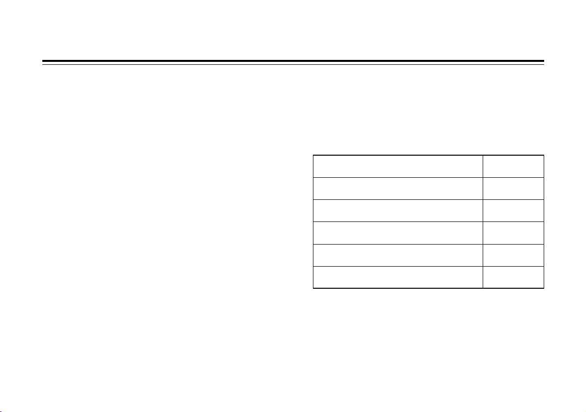
• The approximate input/output time differences of the
AW-EX500 are as shown below.
- 5 -
• The AW-EX500 generates various sync signals internally
on the basis of the signals which are supplied to it. For this
reason, it cannot output normal signals if no signals are
supplied. To use this signal converter, therefore, signals
must be supplied to it.
• The AW-EX500 does not come with a cable compensation
circuit for the input signals. If the cable from the signal
source is too long, use a cable compensator immediately
in front of the AW-EX500 input.
• When signals with significantly high jitter such as from a
VTR are used as the signal source, the output signals may
be disrupted. Particularly when an SDI card is used, the
jitter performance may not satisfy the standard. In a case
like this, shape the sync signals using a TBC (time base
corrector) or other such device at a stage prior to the
AW-EX500 input.
• For further details on the settings and connections of an
optional card, refer to the operating instructions
accompanying the optional card concerned.
• If the AW-PB302 card is used, it will not be possible to use
the composite video signals from the card’s D-sub
connector: therefore, leave the connector unconnected.
Neither can Y/C signals be selected.
Analog composite input —
AW-EX500 1H +
analog output approx. 7.6µsec
Analog composite input —
AW-PB302 1H +
output approx. 5.6µsec
Analog component input —
AW-EX500 1H +
analog output approx. 7.6µsec
Analog component input —
AW-PB302
Approx. 0.4µsec
output
SDI signal input* —
AW-EX500
Approx. 3.6µsec
analog output
SDI signal input* —
AW-PB302
Approx. 2.3µsec
output
*Signal source: AW-E650 + AW-PB504, time difference from
AW-E650 video output
Page 6
OPTION CARD
Y/Y/VIDEO IN
R-Y/C
IN
B-Y
IN
DC12V IN
VIDEO/RGB/COMPONENT/YC OUT
RS232C
SDI
IN
AUDIO IN
1
<
>
;
:
2
3
4
5
6
7
9
8
=
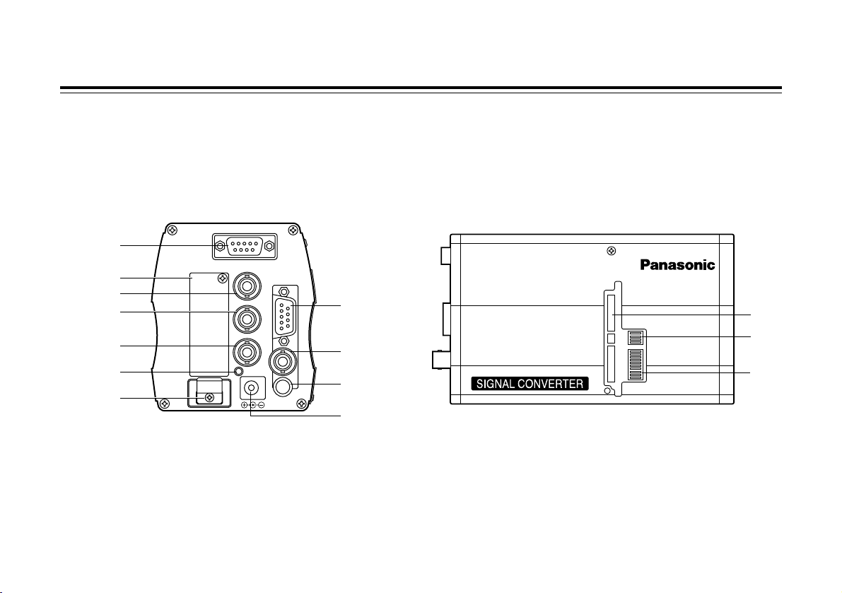
- 6 -
Major operating controls and their functions
<Rear View> <Side View>
Page 7

- 7 -
1
Analog video output connector
[VIDEO/RGB/COMPONENT/YC OUT]
The analog video signals are output from this D-sub 9-pin
connector.
The video signal is always output from pin #6. Depending
on the position of function setting switch 2 =, RGB,
COMPONENT or YC analog video signals are output
from pins #3, #4 and #5. It is also possible to set whether
to add a SYNC signal to the RGB signals.
The SYNC signal (4Vp-p) is output from pin #7.
WV-CA9T5 can be used as the connecting cable.
The pin layout is shown below.
2
RS-232C connector [RS232C]
This enables RS-232C communication via the AW-EX500
between a PC or other device and a device which
supports RS-232C communication and which is installed
in the optional card slot or additional interface.
The position for either the optional slot or additional slot
must be selected using function setting switch 1 <for the
other party to the communication.
This connector cannot be used by AW-PB302,
AW-PB304, AW-PB307, AW-PB309, AW-PB310 or
AW-PB504.
3
SDI input connector [SDI IN]
The SDI signals are supplied to this connector which is
terminated internally by a 75Ω resistance.
Connect 270Mbps signals which satisfy the SMPTE259M
standard.
Switch the input signal setting to SDI input using function
setting switch 1 <.
When the output of the AW-PB504 is connected, the
maximum cable length is 200 or so meters which is
equivalent to BELDEN 8281.
Pin No. Signal
1 VIDEO GND
2 RGB GND
3 R/R-Y/C
4 G/Y/Y
5 B/B-Y
6 VIDEO
7 SYNC
8 SYNC GND
9NC
Back of the connector
Page 8

4
Audio input connector [AUDIO IN]
The audio signals are supplied to this connector. Input
signals with a level of –20dBV.
This is a stereo mini plug jack.
The audio signals of the AW-PB310 can be supplied to it.
This connector cannot be used by AW-PB302,
AW-PB304, AW-PB307, AW-PB309 or AW-PB504.
5
Analog video (Y/Y/VIDEO) input connector
[Y/Y/VIDEO IN]
The analog video signals are supplied to this connector
which is terminated internally by a 75Ω resistance.
Switch the setting to match the input signal using function
setting switch 1 <.
6
Analog video (R-Y/C) input connector [R-Y/C IN]
The analog video signals are supplied to this connector
which is terminated internally by a 75Ω resistance.
Switch the setting to match the input signal using function
setting switch 1 <.
7
Analog video (B-Y) input connector [B-Y IN]
The analog video signals are supplied to this connector
which is terminated internally by a 75Ω resistance.
Switch the setting to match the input signal using function
setting switch 1 <.
8
Power LED
This lights up red when DC power is supplied to the DC
12V input connector 9.
9
DC 12V input connector [DC12V IN]
Connect the DC 12V power supply (2A or more) here
using the AW-CA4T1 DC power cable.
(Recommended AC adaptor: AW-PS505)
:
Optional card slot
This slot is used for optional cards. For further details,
refer to the operating instructions accompanying the
optional cards concerned.
;
Cable clamp
This is used to clamp the AW-CA4T1 DC power cable
connected to the DC 12V input connector 9to prevent it
from moving out of place.
- 8 -
Major operating controls and their functions
Page 9

<
Function setting switch 1
This is used to select the operations of the AW-EX500.
Before changing a setting, the power must be turned off.
The setting items are shown below.
1: Input signal setting 1 <SDI/ANALOG>
(Factory setting: ANALOG)
Set this to match the input signals which will be used.
2: Input signal setting 2 <YR-YB-Y, YC/VIDEO>
(Factory setting: VIDEO)
3: Input signal setting 3 <YR-YB-Y/YC>
(Factory setting: YC)
Input signal settings 2 and 3 take effect when
<ANALOG> has been selected as input signal setting 1.
Set as shown below to match the analog signals which
are to be input to analog video input connectors 5, 6
and 7.
4: Input signal level setting Y <714mV/700mV>
(Factory setting: 700mV)
When analog component signals have been selected
as the input signals, select this setting by determining
whether the white 100% signal level of the input
signals is 714mV or 700mV.
When VIDEO signals or YC signals are to be input, set
to 700mV.
5: Input signal level setting R-YB-Y <756mV/525mV>
(Factory setting: 525mV)
When analog component signals have been selected
as the input signals, select this setting by determining
whether the color signal level of the input signals is
756mV or 525mV.
When VIDEO signals or YC signals are to input, set to
525mV.
- 9 -
1
2
3
4
5
6
7
8
9
0
O
N
INPUT SEL2 INPUT SEL3 Input signal
VIDEO Y/C VIDEO
VIDEO YR-YB-Y VIDEO
YR-YB-Y, Y/C Y/C Y/C
YR-YB-Y, Y/C YR-YB-Y YR-YB-Y
ON OFF SW NO
PB302 PB310 ADDITIONAL I/F SEL 0
PB302 PB310 OPTION I/F SEL 9
YR-YB-Y RGB PB302 OUT SEL (ADD) 8
YR-YB-Y RGB PB302 OUT SEL (OPT) 7
ADDITIONAL IF OPTION IF RS232C SEL 6
756mV 525mV INPUT LEVEL R-YB-Y 5
714mV 700mV INPUT LEVEL Y 4
YR-YB-Y YC INPUT SEL3 3
YR-YB-Y, YC VIDEO INPUT SEL2 2
SDI ANALOG INPUT SEL1 1
Page 10

- 10 -
6: RS232C select <ADDITIONAL IF/OPTION IF>
(Factory setting: OPTION IF)
This setting is used to select either the optional card slot
or additional card slot as the destination for the
connection of the RS-232C connector 2 on the rear
panel of the signal converter. At the <OPTION IF>
setting, the connector is connected to the optional card
which has been plugged into the optional card slot.
7: Optional card slot AW-PB302 output setting
<YR-YB-Y/RGB> (Factory setting: RGB)
This setting is used to select the signal to be output
from the connector on the AW-PB302 (RGB card)
when the AW-PB302 has been plugged into the
optional card slot.
The setting has no effect when a card other than the
AW-PB302 has been plugged into the slot.
8: Additional card slot AW-PB302 output setting
<YR-YB-Y/RGB> (Factory setting: RGB)
This setting is used to select the signal to be output
from the connector on the AW-PB302 (RGB card)
when the AW-PB302 has been plugged into the
additional card slot using the AW-EX100.
The setting has no effect when a card other than the
AW-PB302 has been plugged into the slot.
9: Optional card slot optional card setting
<PB302/PB310> (Factory setting: PB310)
Set this to <PB302> for use when the AW-PB302 card
is to be plugged into the optional card slot;
alternatively, set it to <PB310> for use when the
AW-PB310 is to plugged in.
The setting has no effect when a card other than the
AW-PB302 or AW-PB310 has been plugged into the
slot.
0: Additional card slot optional card setting
<PB302/PB310> (Factory setting: PB310)
Set this to <PB302> for use when using the
AW-EX100 to plug the AW-PB302 card into the
additional card slot; alternatively, set it to <PB310> for
use when the AW-PB310 is to plugged in.
The setting has no effect when a card other than the
AW-PB302 or AW-PB310 has been plugged into the
slot.
Major operating controls and their functions
Page 11

=
Function setting switch 2
This is used to select the operations of the AW-EX500.
Before changing a setting, the power must be turned off.
The setting items are shown below.
1: Output signal setting 1 [D-SUB OUT SEL1]
<YC/RGB, YR-YB-Y>
(Factory setting: RGB, YR-YB-Y)
2: Output signal setting 2 [D-SUB OUT SEL2]
<RGB/YR-YB-Y> (Factory setting: YR-YB-Y)
These are used to select the signals to be output to pins
#3, #4 and #5 of analog video output connector 1.
The switch combinations are shown below.
- 11 -
3: Analog RGB output SYNC addition setting
<SYNC ON/SYNC OFF>
(Factory setting: SYNC OFF)
This is used to set whether to add the SYNC signal to
the RGB signals when RGB has been selected as the
analog video output setting.
At SYNC ON, the SYNC signal is added to the R, G
and B signals.
4: Not used <ON/OFF>
(Factory setting: OFF)
Keep this at the factory setting.
>
Additional card slot
Remove the cover, and connect the AW-EX100 additional
card box.
1
2
3
4
O
N
D-SUB OUT SEL1 D-SUB OUT SEL2
Output signal
RGB, YR-YB-Y YR-YB-Y Component
RGB, YR-YB-Y RGB RGB
Y/C YR-YB-Y Y/C
Y/C RGB Y/C
ON OFF SW NO
—— —— NOT USE 4
SYNC ON SYNC OFF RGB OUT SYNC 3
RGB YR-YB-Y D-SUB OUT SEL 2 2
YC RGB, YR-YB-Y D-SUB OUT SEL 1 1
Page 12

- 12 -
Connections
• Before proceeding with the connections, turn off the power.
• Use the AW-PS505 AC adaptor to supply the power.
Use the AW-CA4T1 power cable.
• For further details on connecting the devices, refer to the operating instructions accompanying
the devices concerned.
• For further details on operating the devices, refer to the operating instructions accompanying
the devices concerned.
Page 13

- 13 -
$ Analog signal input
OPTION CARD
OPTION CARD
Y/Y/VIDEO IN
R-Y/C
IN
B-Y
IN
DC12V IN
VIDEO/RGB/COMPONENT/YC OUT
RS232C
SDI
IN
AUDIO IN
Convertible Camera AW —
E600
ON
POWER
OFF
POWER
O I
FUSE(POWER)
FUSE
FUSE
AC Adaptor
AW-
PS505
*1: For further details on the connections between the
optional cards and devices, refer to the operating
instructions accompanying the cards concerned.
*2: An AW-PB3** card and an AW-PB5** card cannot
be used at the same time.
*3: The AW-PB302, AW-PB304, AW-PB307, AW-PB309
and AW-PB504 do not support audio input.
Optional card*
1
AW-PB302
PB304
PB307
PB309
PB310
PB504
*2
When the AW-E800A, AW-E600, AW-E300A or AW-E300 is
used as the camera, the AW-PB302 card must be plugged
into the camera in order for the AW-CA50T6 to be used.
Optional card*
1
AW-PB302
PB304
PB307
PB309
PB310
PB504*
2
Use a cable compensator as required.
Coaxial cable (BELDEN 8281 or equivalent)
VIDEO ...........................1
Y/C ................................2
Component....................3
Coaxial cable for
video signals
VIDEO OUT
Zoom Lens Camera
AW-EX500 AW-EX100
DC Power Cable
AW-CA4T1
AC adaptor AW-PS505
AC120V
60Hz
–20dBv
WV-CA9T5
Microphone*
3
Amplifier
Compensator
or
for Y/C, Component signal
AW-CA50T6
Video monitor
Page 14

- 14 -
Connections
OPTION CARD
OPTION CARD
Y/Y/VIDEO IN
R-Y/C
IN
B-Y
IN
DC12V IN
VIDEO/RGB/COMPONENT/YC OUT
RS232C
SDI
IN
AUDIO IN
Convertible Camera AW —
E600
ON
POWER
OFF
POWER
O I
FUSE(POWER)
FUSE
FUSE
AC Adaptor
AW-
PS505
$ SDI signal input
Optional card*
1
AW-PB302
PB304
PB307
PB309
PB310
PB504*
2
Optional card*
1
AW-PB302
PB304
PB307
PB309
PB310
PB504*
2
Zoom Lens Camera + SDI Card
AW-EX500 AW-EX100
DC Power Cable
AW-CA4T1
AC adaptor AW-PS505
AC120V
60Hz
WV-CA9T5
SDI OUT
Coaxial cable
(BELDEN 8281 or equivalent)
Max. 200 m
*1: For further details on the connections between the
optional cards and devices, refer to the operating
instructions accompanying the cards concerned.
*2: An AW-PB3** card and an AW-PB5** card cannot
be used at the same time.
*3: The AW-PB302, AW-PB304, AW-PB307, AW-PB309
and AW-PB504 do not support audio input.
Amplifier
Microphone*
3
Video monitor
Page 15

- 15 -
Attaching the rubber feet
• Adhere the accessory rubber feet to the bottom panel
when the AW-EX500 is to be placed on the floor for use.
Rubber feet
Standard accessories
O
Rubber feet ..................................................................... 4
Page 16

OPTION CARD
Y/Y/VIDEO IN
R-Y/C
IN
B-Y
IN
DC12V IN
VIDEO/RGB/COMPONENT/YC OUT
RS232C
SDI
IN
AUDIO IN
AW-
5-11/16”
(145 mm)
3/8”
(10 mm)
3-3/4”
(96 mm)
3-5/16”
(84 mm)
- 16 -
Appearance
Unit: inch (mm)
Dimensions: 3-5/16” (W) ~ 3-3/4” (H) ~ 6-1/8” (D)
84 ~ 96 ~ 155 mm
Weight: Approx. 1.98 lbs (0.9 kg)
Page 17

- 17 -
Specifications
Input
DC 12V power input connector
270Mbps SDI (BNC) (SMPTE259M standard-compliant) Only video data supported
Analog composite (BNC) 1.0Vp-p (0% setup level)
Analog Y/C (BNC) Y: 1.0Vp-p (0% setup level)
(BNC) C: 0.286Vp-p
Analog component Y: 1.0Vp-p (0% setup level)
(BNC) (714/700mVp-p selectable by switch)
(BNC) R-Y, B-Y: 756/525mVp-p (selectable by switch)
Audio (stereo mini jack) –20dBV, 1 kΩ input impedance
Output
Analog composite 1.0Vp-p (0% setup level)
Analog Y/C Y: 1.0Vp-p (0% setup level)
C: 0.286Vp-p
Analog component Y: 1.0Vp-p (0% setup level)
R-Y, B-Y: 756mVp-p
Analog RGB RGB: 0.7Vp-p
SYNC: 0.3Vp-p (SYNC ON/OFF selectable by switch)
SYNC 4Vp-p
Power requirements: 12 V DC
Power consumption: 6.85 W
indicates safety information.
Page 18

- 18 -
Specifications
Input/output interface: RS-232C
Operating temperature: 14°F to 113°F (–10°C to +45°C)
Operating humidity: 30 % to 90 % (without condensation)
Dimensions (W!H!D): 3-5/16”!3-3/4”!6-1/8” [84!96!155 mm]
Weight: Approx. 1.98 lbs (0.9 kg)
Switch/control functions: • INPUT SEL1 SDI/ANALOG
• INPUT SEL2 YR-YB-Y, YC/VIDEO
• INPUT SEL3 YR-YB-Y/YC
• INPUT LEVEL Y 714mV/700mV
• INPUT LEVEL R-YB-Y 756mV/525mV
• RS232C SEL ADDITIONAL IF/OPTION IF
• PB302 OUT SEL (OPT) YR-YB-Y/RGB
• PB302 OUT SEL (ADD) YR-YB-Y/RGB
• OPTION I/F SEL PB302/PB310
• ADDITIONAL I/F SEL PB302/PB310
• D-SUB OUT SEL1 YC/RGB, YR-YB-Y
• D-SUB OUT SEL2 RGB/YR-YB-Y
• RGB OUT SYNC SYNC ON/SYNC OFF
Weight and dimensions indicated are approximate.
Specifications are subject to change without notice.
Page 19

- 19 -
Page 20

PANASONIC BROADCAST & TELEVISION SYSTEMS COMPANY
UNIT COMPANY OF MATSUSHITA ELECTRIC CORPORATION OF AMERICA
Executive Office:
One Panasonic Way 4E-7, Secaucus, NJ 07094 (201) 348-7000
EASTERN ZONE:
One Panasonic Way 4E-7, Secaucus, NJ 07094 (201) 348-7621
Southeast Region:
1225 Northbrook Parkway, Ste 1-160, Suwanee, GA 30024 (770) 338-6835
Central Region:
1707 N Randall Road E1-C-1, Elgin, IL 60123 (847) 468-5200
WESTERN ZONE:
3330 Cahuenga Blvd W., Los Angeles, CA 90068 (323) 436-3500
Government Marketing Department:
52 West Gude Drive, Rockville, MD 20850 (301) 738-3840
Broadcast PARTS INFORMATION & ORDERING:
9:00 a.m. – 5:00 p.m. (EST) (800) 334-4881/24 Hr. Fax (800) 334-4880
Emergency after hour parts orders (800) 334-4881
TECHNICAL SUPPORT:
Emergency 24 Hour Service (800) 222-0741
Panasonic Canada Inc.
5770 Ambler Drive, Mississauga, Ontario L4W 2T3 (905) 624-5010
Panasonic de Mexico S.A. de C.V.
Av angel Urraza Num. 1209 Col. de Valle 03100 Mexico, D.F. (52) 1 951 2127
Panasonic Sales Company
Division of Matsushita Electric of Puerto Rico Inc.
San Gabriel Industrial Park, 65th Infantry Ave., Km. 9.5, Carolina, Puerto Rico 00630 (787) 750-4300
 Loading...