

Page 1
FRANÇAIS
DEUTSCH ENGLISH
ITALIANOESPAÑOL
Convertible Camera
AW-E860L
Before attempting to connect, operate or adjust this product,
please read these instructions completely.
Page 2
- 1 (E) -
1
indicates safety information.
$
DO NOT REMOVE PANEL COVER BY
UNSCREWING.
To reduce the risk of electric shock, do not remove
cover. No user serviceable parts inside.
Refer servicing to qualified service personnel.
WARNING:
TO REDUCE THE RISK OF FIRE OR SHOCK
HAZARD, KEEP THIS EQUIPMENT AWAY
FROM ALL LIQUIDS-USE AND STORE ONLY
IN LOCATIONS WHICH ARE NOT EXPOSED
TO THE RISK OF DRIPPING OR SPLASHING
LIQUIDS, AND DO NOT PLACE ANY LIQUID
CONTAINERS ON TOP OF THE EQUIPMENT.
CAUTION:
TO REDUCE THE RISK OF FIRE OR SHOCK
HAZARD AND ANNOYING INTERFERENCE,
USE THE RECOMMENDED ACCESSORIES
ONLY.
Note:
The rating plate (serial number plate) is on the
bottom of the unit.
ENGLISH VERSION
Page 3

- 2 (E) -
ENGLISH
The information marking of this product may be found on the
bottom of the product.
The serial number of this product may be found on the
bottom of the product.
You should note the serial number of this product in the
space provided and retain this book as a permanent record
of your purchase to aid identification in the event of theft.
Model No.
Serial No.
CONTENTS
Preface ............................................................................... 3
Features .............................................................................. 4
Special notes on operation ................................................. 5
Precautions ......................................................................... 6
Major operating controls and their functions ....................... 8
Mounting ........................................................................... 12
Flange back adjustment (For zoom lens) ......................... 14
Iris gain control in a lens ................................................... 15
Connections ...................................................................... 16
Adjustment ........................................................................ 21
Use mode setting .............................................................. 27
Menu item setting ............................................................. 29
Setting and changing the optional cards ........................... 50
Setting to initial set ............................................................ 51
Appearance ...................................................................... 55
Specifications .................................................................... 56
Standard accessories ....................................................... 58
Caution:
Before attempting to connect or operate this product,
please read these instructions completely.
Page 4

- 3 (E) -
• The Panasonic AW-E860L is a digital signal processing
colour video camera that incorporates three 2/3” wide
CCDs. A digital video signal processing system is packed
in a compact, lightweight body while assuring high picture
quality, high reliability and high performance.
• System setup and adjustments can be easily performed by
following the setup menu.
• Connection to peripheral devices, such as a RCU, a RCB
and a lens and the camera pan/tilt unit enables a wide
variation of system configurations.
• Option cards may also be installed.
❈ The following cards are not available for AW-E860;
· AW-PB301 Component studio card:
Use AW-PB305.
· AW-PB302 RGB card:
The camera unit contains this function.
· AW-PB303 High-sensitivity card
· AW-PB304 SDI card:
Use AW-PB504.
· AW-PB306 Studio SDI card:
Use AW-PB506.
· AW-PB307 SVGA card
· AW-PB309 WEB card
· AW-PB310 IEEE 1394 card
Preface
Note
In order to protect the environment when the convertible
camera is to be discarded at the end of its service life,
ask a specialized contractor to dispose of it properly.
Page 5

- 4 (E) -
ENGLISH
1. Digital video signal processing for high quality, high
reliability, high performance, lightweight and compact
size.
2. Resolution: 850 lines (HIGH BAND DTL: ON),
S/N ratio: 63 dB (DNR ON)
3. Minimum illumination: 0.4 lx (F1.7, Night Eye H mode)
4. SET UP menu for system check and readjustments.
5. Built-in automatic controls, including ATW, ELC, and
AGC.
6. CCD readout is switchable between field and frame
modes. Vertical resolution can be stepped up in frame
mode and it is effective for shooting still objects.
7. The built-in synchronized scanning system reduces
noise in computer graphics.
8. Various correction circuits permit video reproduction with
high fidelity.
9. Chroma detail correction enables clear shots of dark
colour objects.
10. A dark detail circuit provides natural edge correction to
any object in a dark scene.
11. The 12-axis digital colour matrix enables users’ to create
images of their choice.
12. Four use modes for each of your specific applications
can be selected.
13. Full colour bar is indicated on the monitor screen.
14. Remote control with a RCU, RCB or a hybrid control
panel.
15. Aspect ratio is 16:9 and 4:3 selectable.
Features
Page 6

- 5 (E) -
Special notes on operation
• Turn power off before connecting or disconnecting cables.
• Connection or disconnection of any studio cable, RCB
cable or other cable to any unit of equipment must be
performed while power is off.
• While the camera is in automatic mode;
Shooting of bright objects in ELC operation mode may
result in a smeared picture unique to the CCD.
The ATW function under fluorescent illumination can
adversely change the white balance.
• There is a cooling fan inside. It is an expendable part, and
must be replaced about every 30000 hours. (Whenever fan
replacement is necessary, be sure to ask the store where
you purchased the set.)
Page 7

- 6 (E) -
ENGLISH
Precautions
DON’TS
• Do not attempt to disassemble the camera, remote control
unit (RCU) or other units. In order to prevent electric
shock, do not remove screws or covers. There are no
user-serviceable parts inside.
• Do not abuse the camera. Avoid striking, shaking, etc.
The camera contains sensitive components which could be
damaged by improper handling or storage.
• Do not let the lens remain uncapped when the camera is
not in use. If the lens is not installed, do not leave the lens
mount hole uncovered.
• Do not touch the surface of the lens or prism.
• Do not use strong of abrasive detergents when cleaning
the camera body.
• Do not aim the camera toward the sun, no matter whether
it is turned on or not.
• Do not expose the camera or remote control unit (RCU) to
rain or moisture, and do not try to operate the equipment in
wet conditions. Do not operate the camera or RCU if it
becomes wet.
• Do not operate the camera or remote control unit (RCU)
outdoors during a lightning storm.
• Do not use the camera in an extreme environment where
high temperatures or high humidity exist.
• Do not leave the camera and remote control unit (RCU)
turned on when not in use. Do not unnecessarily turn the
camera power on and off repeatedly. Do not block the
ventilation slots.
• Do not cover the port otherwise block ventilation during
operation. Internal heat buildup can cause a fire.
Page 8

- 7 (E) -
Precautions
DOS
• Refer any servicing to qualified service personnel.
• Handle the camera with care.
• Protect the precision made lens by placing the lens cap
over when the camera is not in use. If the lens is not
installed, protect the surface of the prism by placing the
body cap into the lens mount hole.
• Use a mild blower or lens cleaning tissue designed for
coated lenses, to clean the surface of the lens or prism in
the event that it should become dirty.
• Use a dry cloth to clean the camera if it is dirty. In case the
dirt is hard to remove, use mild detergent and wipe gently.
• Use caution when operating the camera in the vicinity of
spot lights or bright lights, as well as light reflecting objects
and surfaces.
• Take immediate action if ever the camera or RCU should
become wet. Turn the power off and have the unit checked
by an authorized service facility.
• Follow normal safety precautions to avoid personal injury.
• Use the camera in an environment where the temperature
is within –10°C to +45°C and the relative humidity is within
30 % to 90 %.
• Always turn the power off when the camera is not going to
be used. Operate the camera and RCU only when there is
adequate ventilation.
Page 9
- 8 (E) -
ENGLISH
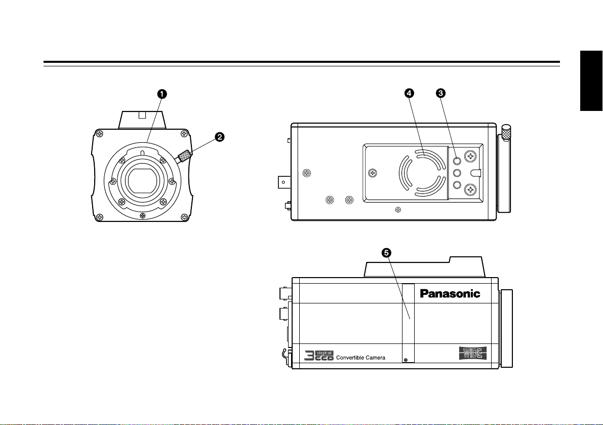
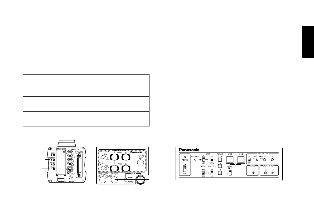
Major operating controls and their functions
<Front view> <Top view>
<Side view>
Page 10
- 9 (E) -
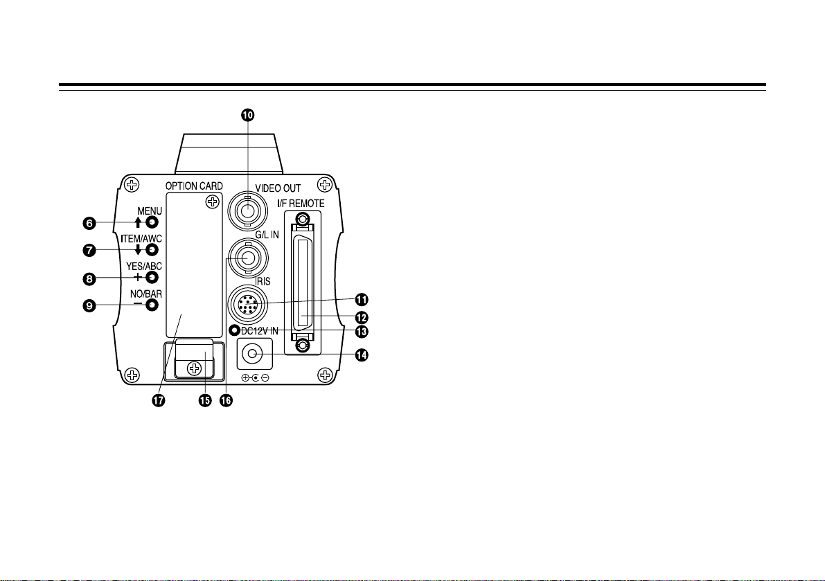
Major operating controls and their functions
1 Lens mount
2/3” Standard bayonet type (B4 mount) lens or a
microscope adapter can be mounted.
2 Lens fixing ring knob
Rotate the lens fixing ring knob counterclockwise and
remove the lens mount cap. Mount the lens on the
camera and rotate the lens fixing ring knob clockwise in
order to fix the lens securely.
3 Mounting hole
A screw hole (1/4” - 20 UNC) for mounting the camera on
a wall, ceiling with a mounting bracket or tripod.
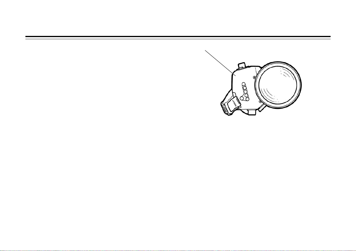
4 Cooling fan
• Do not cover the port or otherwise block ventilation
during operation. Internal heat buildup can cause a fire.
• The cooling fan has a service life of about 30000 hours.
(at a room temperature of 25°C) Replace the fan that
has come to the end of its service life. (If the fan is used
at a room temperature of 35°C and above, replace it
about 30% sooner.)
Whenever fan replacement is necessary, be sure to ask
the store where you purchased the set.
5 Expansion slot
Remove the cover, and connect the expansion card box.
For details, refer to the manual for expansion card box.
Page 11
6 MENU switch (MENU/A)
A menu will appear on the monitor screen when this
switch is pressed for about 5 seconds. This item can be
selected by pressing the switch while the menu is on the
screen.
7 ITEM/AWC switch (ITEM/AWC/S)
The item just below can be selected by pressing this
switch while the menu is on the screen. When the menu
is not displayed or the camera is in shooting mode, the
automatic white balance control can be set with this
switch.
8 YES/ABC switch (YES/ABC/+)
The Sub Menu for each item of the Main Menu is
displayed when this switch is pressed while the Main
Menu is on the screen.
While the Sub Menu is displayed, any setting can be
brought up to a higher value with this switch. When the
menu is not displayed or the camera is in shooting mode,
the automatic black balance control can be set with this
switch.
9 NO/BAR switch (NO/BAR/–)
The item just below can be selected by pressing this
switch while the Sub Menu is on the screen.
While the Sub Menu is displayed any setting can be
brought down to a lower value with this switch. When the
menu is not displayed or the camera is in shooting mode,
the colour bar and the shooting conditions are alternately
indicated by pressing the switch.
: Video output connector (VIDEO OUT)
A composite video signal is provided at this connector.
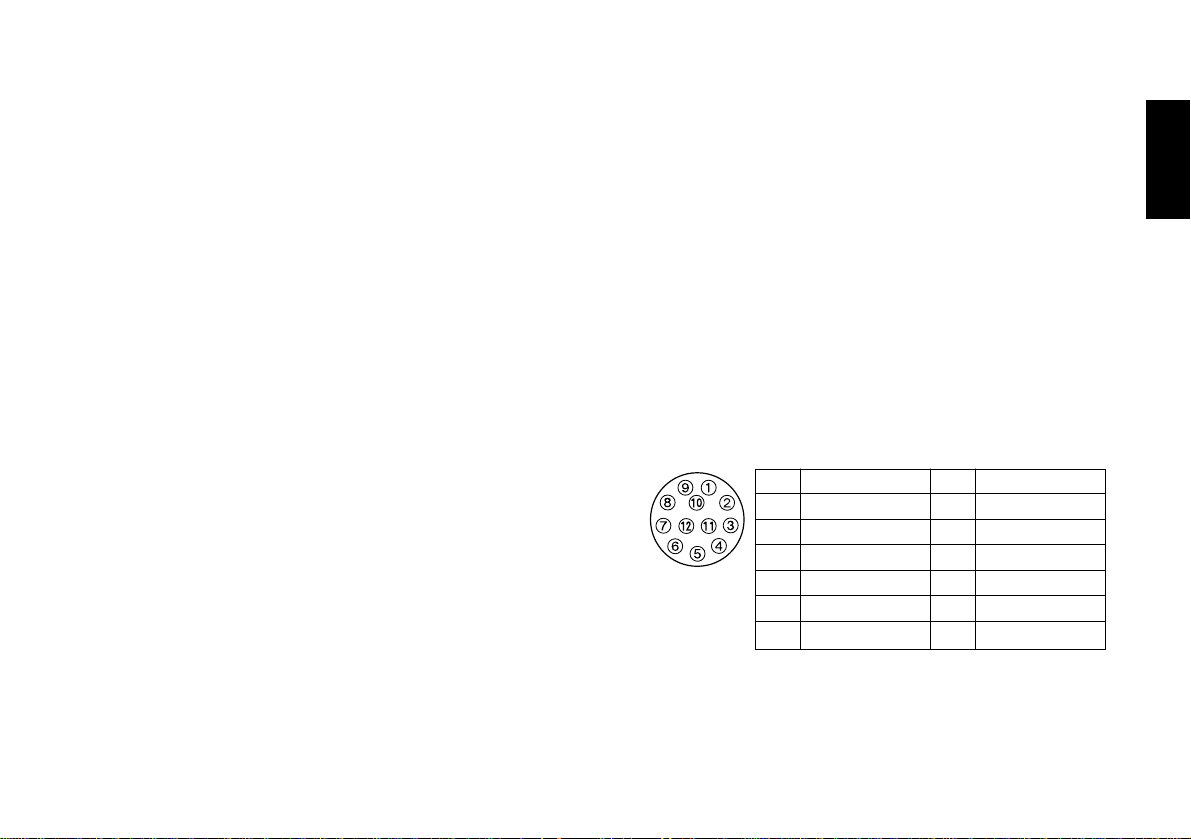
; Iris connector (IRIS)
Input terminal for lens with an iris control function.
- 10 (E) -
ENGLISH
Pin No.
Signal
1 Return Control
2 Not Used
3 GND
4
Auto/Manual Control
5 Iris Control
6 Lens Power
Pin No.
Signal
7 Iris Follow
8
Auto/Remote Control
9 Not Used
10 Not Used
11 Not Used
12 Not Used
Page 12

< I/F Remote connector (I/F REMOTE)
Input terminal dedicated to control signals from the
optional remote control box (RCB) (WV-CB700A, etc.)
and the RCU (WV-RC700A, WV-RC550, etc.) and the
camera pan/tilt unit (AW-PH400, etc.).
• WV-CB700A is connected through the optional RCB
cable (AW-CA50T10/AW-CA50B10).
• WV-RC700A/WV-RC550 is connected through the
optional RCU cable (AW-CA50A26).
• AW-CB400 is connected through the optional camera
control cable (AW-CA50T8).
= Power indicator
Red LED lamp lights to indicate that the specified DC
power is supplied to the camera.
> DC 12 V input connector (DC 12V IN)
12 V DC is supplied through the DC power supply cable
(DC cable with ø6.5 plug supplied with AW-PS505A).
(Recommended AC adapter: AW-PS505A)
? Cable clamp
Clamp the DC power supply cable connected to the DC
12 V input connector to prevent it from slipping out.
@ G/L input connector (G/L IN)
Signals synchronized with the reference signal are to be
supplied to this connector when the camera is to be
synchronized with the reference signal BB.
A Optional card slot
Slot for inserting an optional card. For details, refer to the
manual for optional cards.
- 11 (E) -
Major operating controls and their functions
Cautions
1. Connect this to a DC 12 V class 2 power supply only.
2. To prevent fire or shock, the UL listed wire
VW-1, style 1007 should be used as for the cable for
DC 12 V input connector.
Page 13
- 12 (E) -
ENGLISH
Mounting
• Lenses of any make can be mounted on the camera as
long as they are equipped with a 2/3” standard bayonet.
• Use the lens extension cable AW-CA12T12A (6”/15 cm) if
your lens cable is too short.
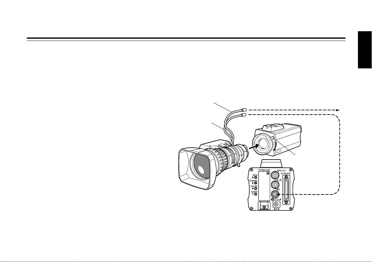
1. Lens mounting
Rotate the lens fixing ring knob counterclockwise and
remove the lens mount cap. Mount the lens on the
camera and rotate the lens fixing ring knob clockwise in
order to fix the lens securely. Connect the camera cable
to the IRIS connector on the back panel of the camera.
Control cable
Camera cable
To lens I/F connector
of camera pan/tilt unit
To iris connector
Lens fixing ring
knob
Page 14
- 13 (E) -
Mounting
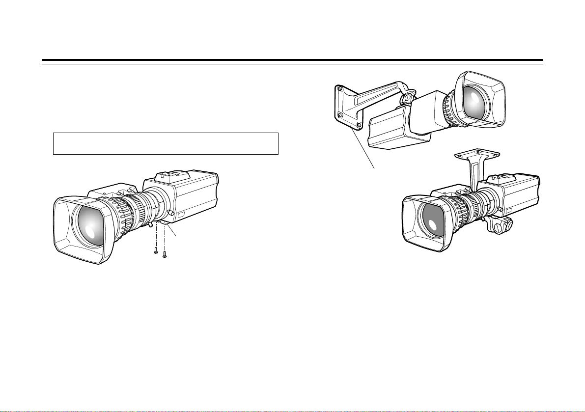
2. Camera mounting
1. To mount a camera on a pan/tilt head or a mounting
bracket or the like, attach the mounting adapter
(supplied) to the bottom of the camera in case of bottom
mounting.
2. Fix the camera mounting base, pan/tilt unit, and tripod
securely in the screw hole (1/4”-20UNC) of the camera or
the mounting adapter.
3. If the camera cannot be securely fixed, mount the camera
on a mounting bracket or the like with the supplied rubber
sheet between the camera and it.
4. To mount the camera on the pan/tilt head, use a driver in
order to fix it securely.
$ Preventing the camera from falling or coming off
OWhen attaching a camera to the pan/tilt head (AW-PH400,
etc.), follow the directions in the Operating Instructions to fix
the camera firmly in position.
In addition, link the camera to the pan/tilt head using the safety
chain and the mounting screws to help ensure the camera
does not fall.
OWhen attaching the camera on any mounting or other pan/tilt
head, check that the mounting can safely bear the total weight
of the camera, lens, connection cables, etc., fix the camera
firmly in position using the prescribed tool, and take
appropriate measures to prevent the camera from falling.
When changing the camera mounting adapter, use a
screwdriver or similar tool to tighten the screws firmly.
Mounting adapter
Camera mounting bracket (WV-831)
Page 15
- 14 (E) -
ENGLISH
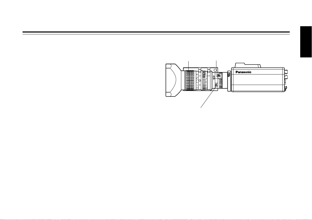
Flange back adjustment (For zoom lens)
1. Fully open the iris by shooting a dark object. (Iris
selection switch should be set to M.)
2. Loosen the flange back lock knob.
3. Aim the camera at any object over 2 meters away from
the camera.
4. Set the lens to its TELE end first and adjust its focus with
the focus ring.
5. Set the lens to its widest angle next and adjust its focus
with the flange back adjust ring.
6. Adjust the focus ring and the flange back adjust ring
alternately for the best focus within the zooming range.
Tighten the flange back lock knob upon completion of
focusing.
7. Turn the iris selection switch to Position A.
FOCUS ring
Flange back lock knob
Flange back adjust ring
Page 16
- 15 (E) -
Iris gain control in a lens
An iris gain control hole is usually provided in the front of the
lens. Adjustment of the iris gain, with a screwdriver through
the hole may be done as follows. (Shape and location of the
hole may vary depending on the type of lens.)
1. Turn the iris selection switch to Position A (AUTO).
2. Rotate the iris gain control to the maximum gain, but in a
range where no hunting or oscillating of the iris ring
develops.
Iris gain control (G, S)
Automatic iris power zoom lens
Page 17
- 16 (E) -
ENGLISH
Connections
Caution:
The connection and installation should be done by qualified service personnel or system installers.
Refer any servicing to qualified service personnel.
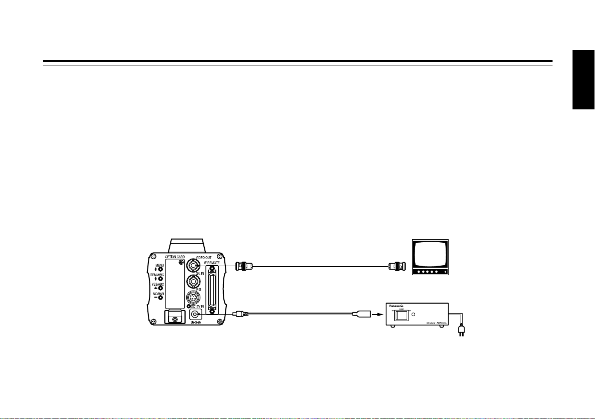
$ Connection of device with a composite input connector
• Connection to any device which has a composite input connector, such as a video monitor or a VTR, must be made through
the VIDEO OUT connector.
• Power supply to the camera must be through the DC cable with ø6.5 plug supplied with AW-PS505A.
• For DC power supply, use the optional AC adapter AW-PS505A.
VIDEO OUT
connector
Video monitor
AC adapter AW-PS505A
VIDEO IN
75 Ω coaxial cable
DC cable with ø6.5 plug
supplied with AW-PS505A
Page 18
- 17 (E) -
Connections
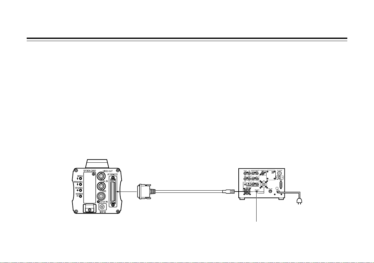
Connection to the RCU (WV-RC700A, WV-RC550) is made
through the optional RCU cable AW-CA50A26.
1. Turn RCU power off before connecting cables.
2. Set the cable selection switch of the RCU to MULTI
(in case of using the WV-RC700A).
3. Connect the 50-pin connector of the RCU cable to the I/F
REMOTE connector of the camera.
4. Turn RCU power on and the power indicator lamp will
light. The camera can now be remote controlled by the
RCU.
Notes:
• The maximum extension distance between the camera
and WV-RC700A is 300 m. The maximum extension
distance between the camera and WV-RC550 is 100 m.
• Use the following options for cable extension.
Studio cable WV-CA26U15 (15 m/50 ft)
WV-CA26U30 (30 m/100 ft)
WV-CA26U100 (100 m/330 ft)
Cable joint adapter
WV-CA26T26
$ Connection of a remote control unit (RCU)
Set to MULTI
WV-RC700A
RCU cable
AW-CA50A26 (15 m)
Page 19
- 18 (E) -
ENGLISH
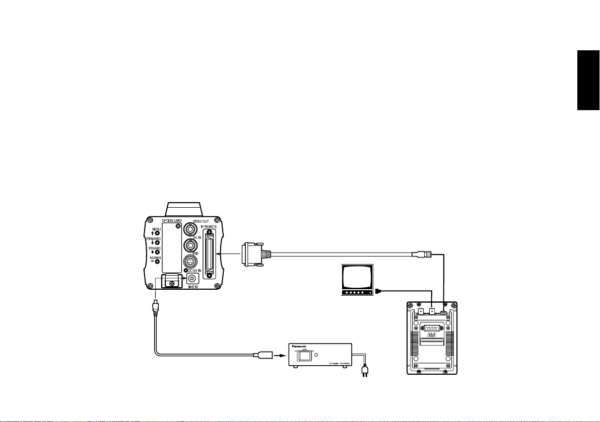
$ Connection of a remote control box (RCB)
The RCB (WV-CB700A) and the camera must be connected
with the optional RCB cable AW-CA50T10.
1. Turn RCB power off before connecting cables.
2. Connect the 50-pin connector of the RCB cable to I/F
REMOTE connector of the camera. The 10-pin connector
must be connected to the RCB.
3. Turn RCB power on and the camera can be controlled
remotely by the RCB.
Notes:
• The monitor output signals of the RCB attenuate and
deteriorate with cable length. It is recommended that the
signals from the monitor output be used for monitoring
purposes only.
• No gen-lock signal is available from the RCB.
• If a longer distance (more than 3 m) is desired between the
camera and the RCB, use the following optional cable.
AW-CA50B10 and WV-CA10B02 (2 m)
WV-CA10B25 (25 m)
WV-CA10B50 (50 m)
AC adapter AW-PS505A
Video signal IN
RCB WV-CB700A
RCB cable AW-CA50T10 (3 m)
MONITOR OUT
DC cable with ø6.5 plug
supplied with AW-PS505A
RCB
Page 20
- 19 (E) -
Connections
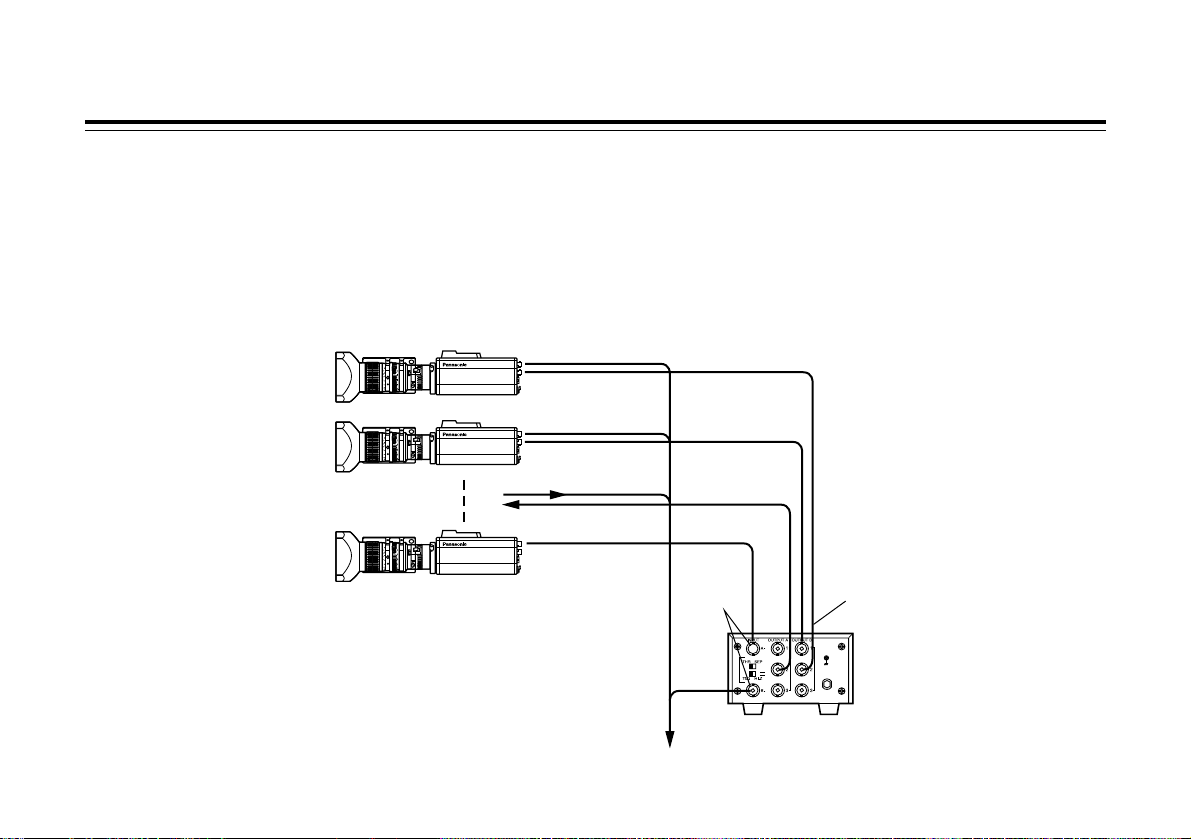
$ Connection with multiple cameras (Colour lock mode)
An example of connection for VBS/BB input (Colour
lock mode).
• One of the multiple cameras is used as the source of
reference signals.
• Supply a synchronizing signal (BB) to the G/L input
connectors of each cameras.
• Do not switch off the camera used for supplying the
reference signals.
• Adjust the SC-phase and H-phase at the video output
connector.
VIDEO OUT
CAMERA
Camera for external sync
(or special effect generator)
G/L IN
VIDEO OUT
OUTPUTINPUT
Video output
To special effect generator or monitoring system
Video distributor
WJ-300C
External sync
signal (BB)
Page 21
- 20 (E) -
ENGLISH
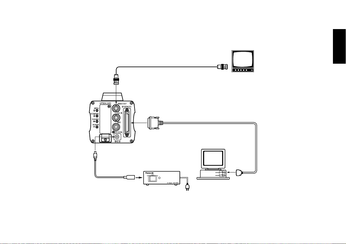
DC cable with ø6.5 plug
supplied with AW-PS505A
Computer
VIDEO OUT connector
AC adapter AW-PS505A
75 Ω coaxial cable
Composite video
input connector
(VIDEO IN)
Video monitor
RS-232C
PC control cable AW-CA50T9 (10m)
$ Connection of computer
The system shown here can remotely control this camera by using a computer.
The software and the cable for RS-232C required for this operation should be obtained locally.
Please contact qualified service personnel for this software.
$ Connection of devices with camera pan/tilt control system
• Refer to the operating instructions of the pan/tilt head to connect camera to it.
Page 22
- 21 (E) -
Adjustment
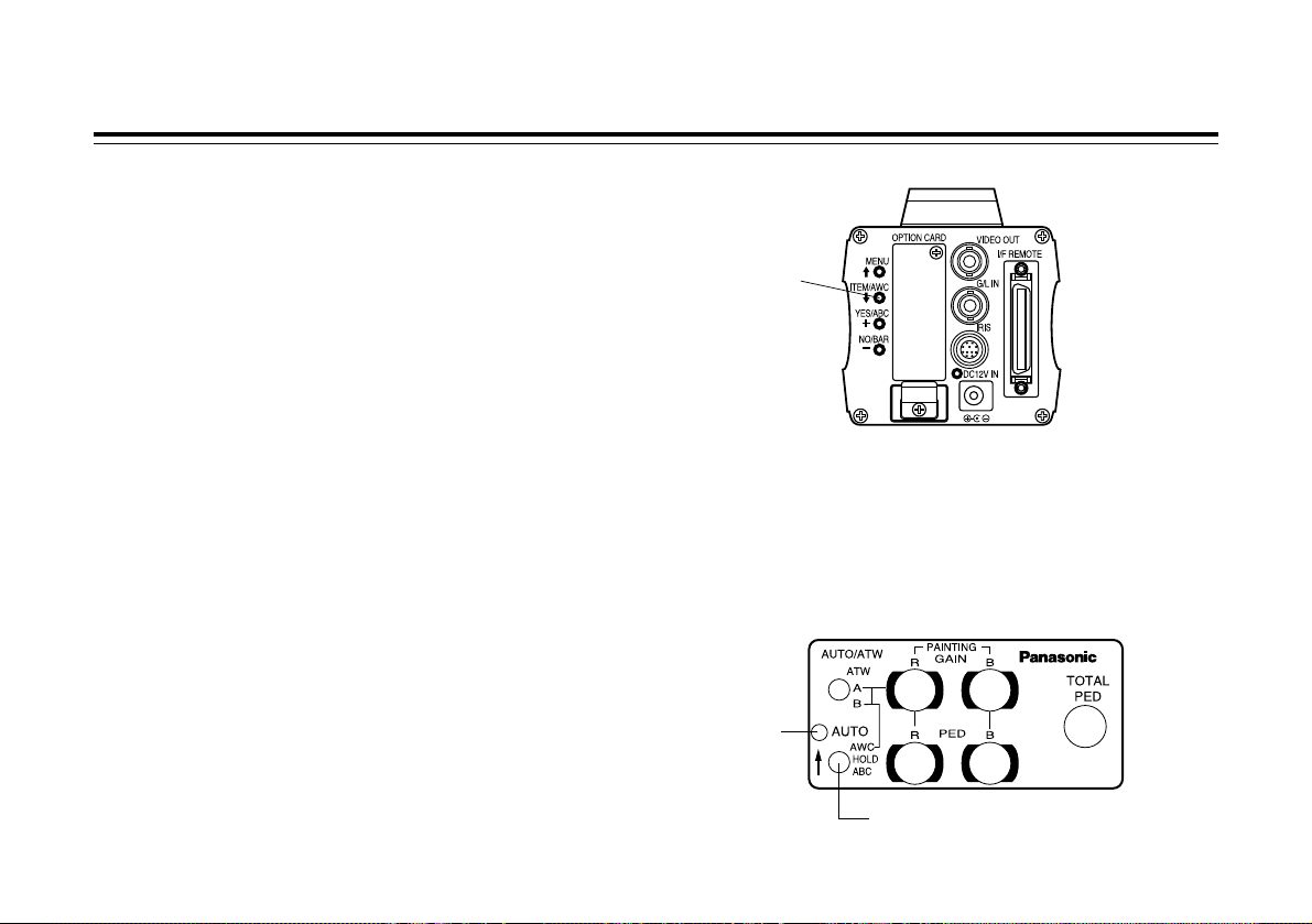
$ Automatic white balance control (AWC)
There are two white balance memories, “AWC A” or “AWC
B” for two different light sources colour temperatures, with
the automatic white balance setting. Then, when the two
different light sources are encountered, you may operate the
camera properly by simply change the white balance mode
to either AWC A or AWC B. There is no need to readjust the
camera to the ambient conditions.
❈ The preset conditions will be renewed whenever you input
new conditions.
1. Turn the white balance selection switch to either “AWC A”
or “AWC B” of RCU or select the white balance mode
either AWC A or AWC B by menu.
2. Aim the camera at a white object (a white wall or a white
handkerchief) and zoom in to enlarge the image as much
as possible.
[ADJUSTMENT by CAMERA]
3. In normal shooting mode:
Press the ITEM/AWC switch for over 2 second.
[ADJUSTMENT with the RCU (RCB, hybrid control panel)]
4. When the AUTO set switch is turned to AWC, the white
balance will be automatically set. While the system is
being set, auto warning indicator (LED) blinks and it goes
out when the white balance setting is completed. If the
lamp remains lit, the setting must be tried again.
RCU (RCB)
CAMERA
AUTO set switch
AUTO LED
ITEM/AWC
switch
Page 23

- 22 (E) -
ENGLISH
Notes:
• For white balance setting aim the camera at a white object
and try to position it in the centre of the monitor screen.
The object must appear in over 10 % of the total monitor
screen area. Try to avoid overly bright objects in the scene.
• White balance may not be correctly set if the lighting of the
object is too weak.
• Since the camera has a built-in memory, the set white
balance will remain in the memory even if power is turned
off. Therefore, it is not necessary to reset the white
balance if the colour temperature of those objects remains
unchanged. However, it must be reset if the colour
temperature changes, such as when you move from
indoors to outside, or vice versa.
• When the camera is used without a RCU or RCB red/blue
gain adjustment of painting setting will be automatically
reset to ±0 after setting the white balance. (painting setting
in only User Mode.)
$
Automatic tracking white balance setting (ATW)
White balance will be automatically set to continuously
match changes of light source and colour temperature while
the white balance setting is set to ATW.
Notes:
• ATW might not function properly when high brightness light
(ex. fluorescent lamp) beams into a screen.
• White balance may not be accurately set if there is no
white object in the scene being shot.
$ Manual white balance setting
[ADJUSTMENT by CAMERA]
Manual setting is possible in User Mode only.
1. Select the white balance mode either AWC A or AWC B
by menu.
2. Aim the camera at a large white object.
Press the ITEM/AWC switch for over 2 second.
3. Adjust the red gain/blue gain control in the Painting item
of Colour Set sub menu of User Mode until the carrier
wave of the white portion of the video signal is at the
minimum width or the white object in the monitor screen
appears pure white. (Use an oscilloscope or a waveform
monitor for precise adjustment.)
[ADJUSTMENT with the RCU (RCB)]
After AWC setting, adjust the R/B GAIN controller in the
same way as described in Step 3 above.
The white object must occupy over
10 % of the monitor screen area.
Page 24
- 23 (E) -
Adjustment
$ Reset to 3200K or 5600K white balance
When the white balance setting is set to either “3200K” or
“5600K” the white balance will be automatically set to the
colour temperature 3200K or 5600K, respectively.
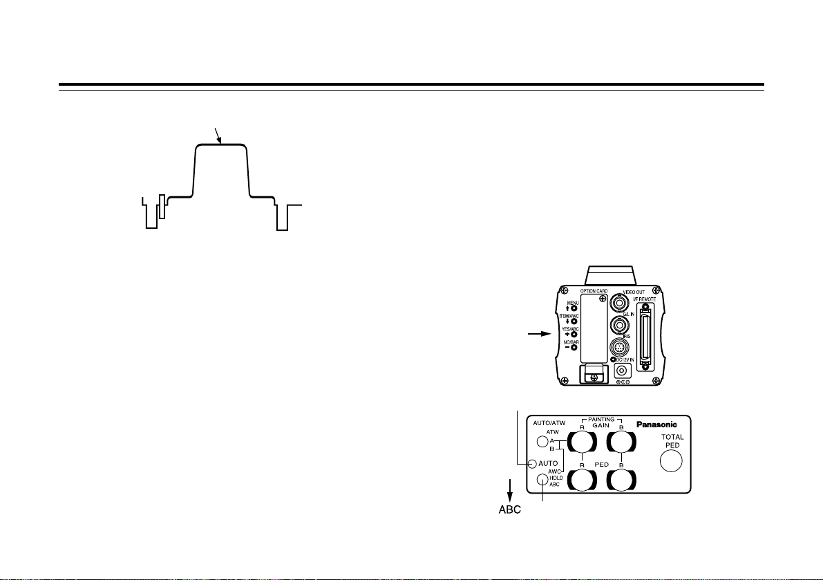
$ Black balance adjustment
• Close the lens.
If the motor drive lens is controlled from the camera, the
lens is automatically closed when the black balance is
adjusted.
• When the camera is used without a RCU or RCB, R/B
pedestal adjustment of painting setting will be
automatically reset to ±0 after setting the black balance.
(painting setting in only User Mode.)
[ADJUSTMENT by CAMERA]
Press the YES/ABC switch for over 2 seconds and the black
balance will be set automatically in 10 seconds.
In user mode, black balance fine adjustment can be
performed with the red pedestal/blue pedestal setting after
setting the black balance.
[ADJUSTMENT with the RCU (RCB, hybrid control panel)]
Set the AUTO set switch to ABC and the black balance will
be automatically set. While the system is being set, the auto
warning indicator (LED) blinks and it goes out when the
black balance setting is completed. If the lamp remains lit,
ABC should be tried again.
Minimize the carrier wave using
the red & blue gain controls
Waveform for white
balance set chart
YES/ABC switch
AUTO set switch
AUTO LED
Page 25
- 24 (E) -
ENGLISH
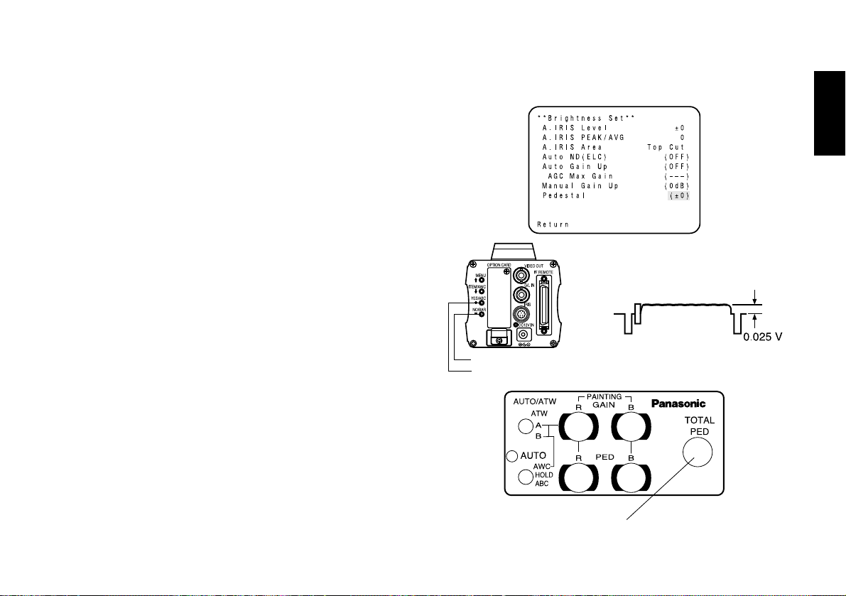
$ Total pedestal level adjustment
(Use an oscilloscope or a waveform monitor for this
adjustment.)
This step is to adjust the black levels (pedestal levels) of two
or more cameras to be the same.
[ADJUSTMENT by CAMERA]
1. Close the lens.
2. Select Pedestal item in the brightness setting Sub Menu.
(Select [Pedestal] in the [Iris, Shutter, Gain Set] sub
menu in User Mode.)
3. Set the pedestal level to 0.025 V with the YES/ABC
switch or the NO/BAR switch.
[ADJUSTMENT with RCU (RCB, hybrid control panel)]
Adjust the pedestal level to 0.025 V with the total pedestal
adjustment.
NO/BAR switch
YES/ABC switch
TOTAL PEDESTAL
Page 26
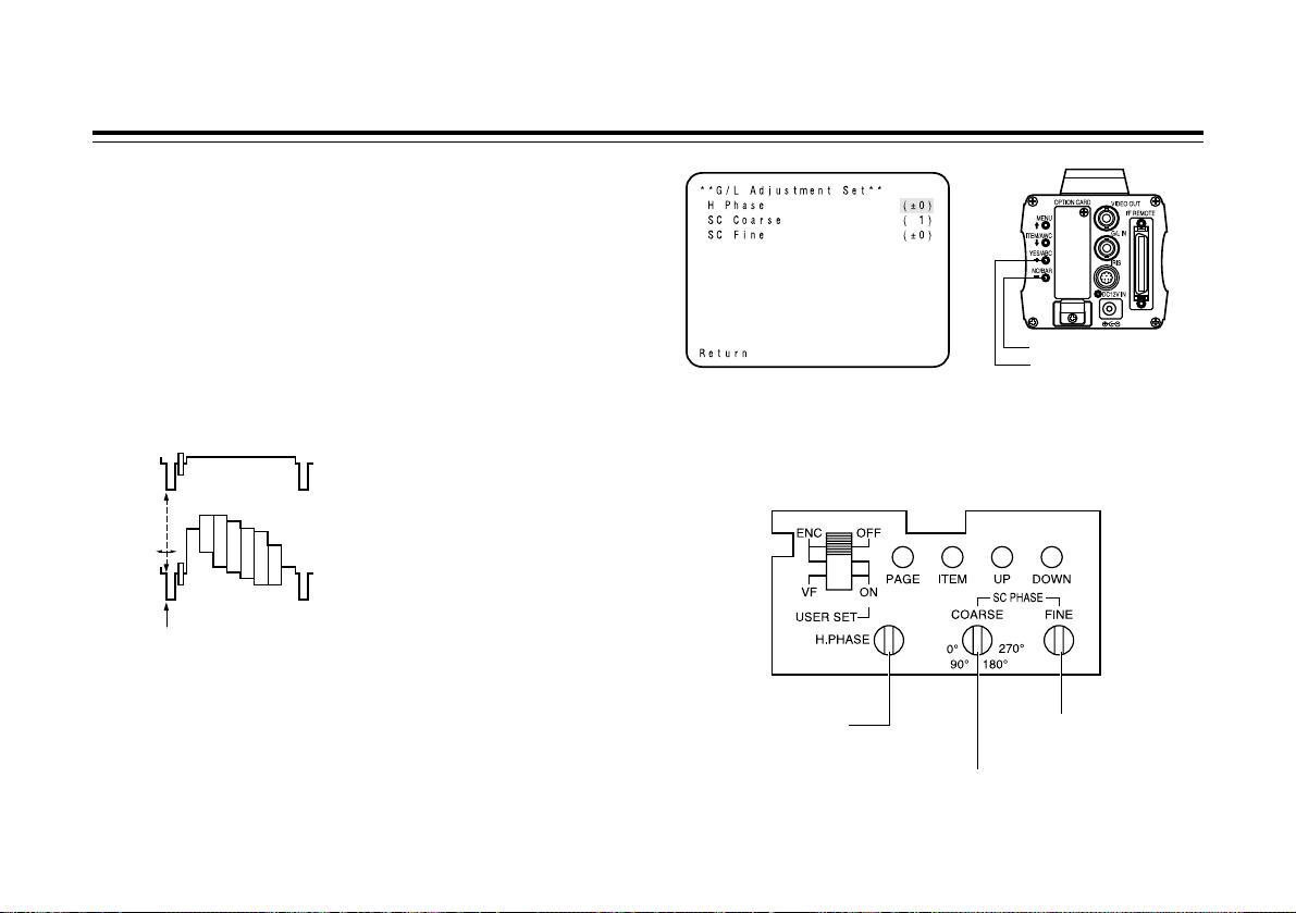
$ Gen-lock adjustment
Phase adjustments must be performed with the camera or
the RCU (RCB) when external synchronizing signals are
supplied to the system in cases where multiple cameras are
used or peripheral devices are connected.
U Horizontal phase control
Observe the waveform of the external synchronizing input
signal (black burst signal) and video output signal on a
two-channel oscilloscope. Then match the horizontal phase
of both signals by adjusting them with the cameras or RCU’s
horizontal phase control.
[ADJUSTMENT by CAMERA]
1. Press the NO/BAR switch for over 5 seconds to display
the colour bar.
2. Select [G/L Adjustment] on the main menu, then select [H
Phase] on the submenu.
3. Adjust the horizontal phase with the YES/ABC and
NO/BAR switch.
[ADJUSTMENT with RCU (RCB, hybrid control panel)]
Use the horizontal phase control.
- 25 (E) -
Adjustment
External gen-lock input signal
(black burst output of special effect
generator)
Video signal
Horizontal phase
control
Subcarrier phase
coarse control
Subcarrier phase
fine control
Adjust the horizontal phase
NO/BAR switch
YES/ABC switch
Page 27
Caution:
• When horizontal phase adjustment is required using RCU
(RCB) or hybrid control panel, BAR/CAM switch should be
set to BAR. Horizontal phase cannot be adjusted if the
switch is in the CAM position. After adjustment set
BAR/CAM switch back to CAM.
• When horizontal phase adjustment is moved, colour phase
is also moved. Adjust colour phase whenever horizontal
phase adjustment is moved.
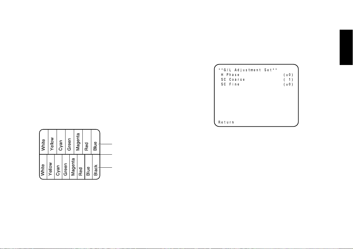
U Colour phase adjustment
Supply the output signal (split colour bar) from the colour
special effect generator to a colour monitor or vectorscope.
Adjust the colour phase of the camera.
[ADJUSTMENT by camera]
1. Press the NO/BAR switch for over 5 seconds for the
colour bar mode.
2. Select [G/L Adjustment] on the main menu, then select
[SC Coarse] on the sub menu.
3. Make coarse adjustment with the YES/ABC switch and
the NO/BAR switch.
4. Select [SC Fine] on the sub menu. Perform fine
adjustment with the YES/ABC switch and the NO/BAR
switch.
[ADJUSTMENT with RCU (RCB, Hybrid control panel)]
Use the subcarrier phase coarse adjustment control and
subcarrier phase fine control.
❈ It is recommended that a vectorscope be used for
maximum accuracy in colour phase adjustment.
Caution:
• When colour phase adjustment is required using RCU
(RCB) or hybrid control panel, BAR/CAM switch should be
set to BAR. Colour phase cannot be adjusted if the switch
is in the CAM position. After adjustment set BAR/CAM
switch back to CAM.
• When horizontal phase adjustment is moved, colour phase
is also moved. Adjust colour phase whenever horizontal
phase adjustment is moved.
- 26 (E) -
ENGLISH
Colour bar of camera
Colour bar of special
effects generator
Sprit line
Page 28
- 27 (E) -
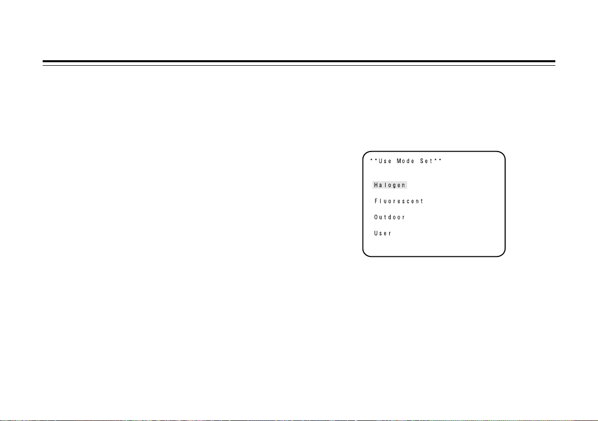
Use mode setting
$ Use Mode Setting
The camera has four use modes, and various functions for
four use modes have been preset.
Functions can be set as best suited to each use mode.
• Halogen mode
Suited to indoor shooting, such as at weddings, parties,
lecture meetings, events, etc.
Settings can be changed using a simple menu.
• Fluorescent mode
Suited to indoor shooting under fluorescent lighting.
Settings can be changed using a simple menu.
• Outdoor mode
Suited to outdoor shooting.
Settings can be changed using a simple menu.
• User mode
Settings can be changed using a detail menu.
$ Setting by camera
1. Turn the camera on while keeping the MENU switch
depressed.
The use mode setting menu shown at right appears on
the monitor screen and one of the use mode blinks.
2. Press the MENU switch, ITEM/AWC switch, or NO/BAR
switch to let the desired use mode blink.
MENU switch (A):
The blinking item moves up by one.
ITEM/AWC switch (S), NO/BAR switch (–):
The blinking item moves down by one.
3. Press the YES/ABC switch.
The blinking use mode comes into effect. After the use
mode setting menu is shown for about 5 seconds, the
camera returns to be ready for operation.
Then, the camera operates in the selected use mode.
Page 29
- 28 (E) -
ENGLISH
Scene File Switch Scene File Switch
Operation mode Position of Position of Hybrid
RCU (RCB) control panel
Halogen Mode 1 1
Fluorescent Mode 2 2
Outdoor Mode 3 3
User’s Mode USER SET 4
$ Setting by RCU (RCB) or hybrid control
panel
An operation mode is selected depending on the position of
the scene file switch.
CAMERA RCU (RCB) Hybrid control panel
MENU
ITEM/AWC
YES/ABC
NO/BAR
SCENE
FILE switch
SCENE FILE switch
Page 30
- 29 (E) -
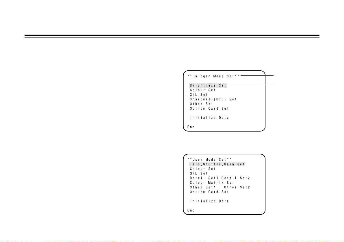
Menu item setting
$ Menu item setting
• Each of the four use modes of the camera has a main
menu. (Shown at right)
• Each item of the main menu has a submenu, which
consists of several settings.
• These settings have been preset to the optimum values to
suit each use mode, and can be changed to suit actual
shooting conditions.
• They can be set from the camera and RCU (RCB).
They can also be set from the hybrid control panel using
the switches, but the setting items are limited because the
menu is not shown.
Notes:
• Composite signals are output from the video output
regardless of the position ENC/VF of the RCU (RCB) user
set switch.
• [End] is displayed only in setting from the camera alone.
• [Option Card1] is shown only when an optional card is
inserted into the camera. [Option Card2] is shown only
when an additional card box is equipped with the camera
and then an optional card is inserted into the camera.
U Main Menu screen
Main menu of Halogen,
Fluorescent, Outdoor Mode
Main menu of User Mode
Use mode
Blinking
Page 31

❈ If the output signal from camera is colour bar, only “G/L
Adjustment Set” screen is displayed.
$ Setting
1. From the camera alone:
Keep the MENU switch depressed for 5 seconds or more.
From RCU (RCB):
Set the user set switch in the pocket to the ON position.
The main menu appears on the monitor screen.
2. Each time the MENU switch (A), ITEM/AWC switch (S),
or NO/BAR switch (–) is pressed, the blinking item moves
up or down.
3. When the YES/ABC switch is pressed after selecting the
desired item to blink, the submenu for the selected item
appears on the screen.
4. Select the desired item to be changed in its settings using
the MENU switch (A) and ITEM/AWC switch (S).
5. Press the YES/ABC switch (+) or NO/BAR switch (–) to
change the settings.
6. Select [Return] using the MENU switch and ITEM/AWC
switch, then press the YES/ABC switch to return to the
main menu.
7. After changing the settings, take the following steps.
Camera alone:
Select [End] using the MENU switch and ITEM/AWC
switch and press the YES/ABC switch.
RCU (RCB):
Set the user set switch in the pocket to the OFF position.
The camera will now operate according to the new settings.
- 30 (E) -
ENGLISH
RCU (RCB)
CAMERA
MENU
ITEM/AWC
YES/ABC
NO/BAR
USER SET switch
Page 32

- 31 (E) -
Menu item setting
1Brightness Set Display
1
–––––
2
–––––
3
–––––
4
–––––
5
–––––
6
––––––
7
–––––
8
–––––
2Colour Set Display
9
–––––
:
–––––
;
–––––
<
––––––
3G/L Adjustment Set Display
=
–––––
>
–––––
?
–––––
4Sharpness (DTL) Set Display
@
–––––
A
––––––
B
–––––
C
–––––
D
–––––
5Other Set Display
E
–––––
F
–––––
G
––––––
H
–––––
I
–––––
J
–––––
K
–––––
L
–––––
$ Sub Menu (Halogen Mode, Fluorescent Mode, Outdoor Mode)
• Settings enclosed in parentheses can be set with the RCU (RCB) switch or VR in RCU (RCB) mode.
• To return to the initial settings, refer to page 51.
Page 33

$
Setting and changing of the setting (Halogen
Mode, Fluorescent Mode, Outdoor Mode)
1 Brightness Set Display
1 Video Level Adjustment [A.Iris Level: –50 to +50]
Convergence level of AUTO IRIS/AUTO GAIN UP/AUTO
ND (ELC) can be adjusted.
2 Detecting Ratio Adjustment
[A.Iris PEAK/AVG: P50 to A50]
The ratio of AUTO IRIS/AUTO GAIN UP/AUTO ND (ELC)
detected peak to average can be adjusted within a
predetermined range.
3 Photometric Measurement Method Setting
[A.Iris Area: All, Centre, Top cut, BTM cut, R/L cut]
A photometric measurement method can be selected for
AUTO IRIS/AUTO GAIN UP/AUTO ND (ELC).
All: All the screen area is measured.
Centre: The screen is measured mainly in the centre
area, about one-third of both the top and
bottom and one-third of both the right and left
portions of the screen are excluded from
measurement.
Top cut: About one-third of the top part of the screen is
excluded from measurement.
BTM cut: About one-third of the bottom portion of the
screen is excluded from measurement.
R/L cut: About one-third of both the right and left
portions of the screen are excluded from
measurement.
4 Auto ND (ELC) Setting [Auto ND (ELC): OFF, ON]
OFF: Luminance is not automatically adjusted by the
electronic shutter.
ON: The electronic shutter is controlled to automatically
adjust the luminance.
- 32 (E) -
ENGLISH
Notes
• ON is automatically selected when the electronic shutter
(F) on the submenu [Other Set] is set to [Auto ND].
OFF is selected when other than [Auto ND] is selected.
• ON is selected when the SHUTTER switch is set to
[ELC] in RCU (RCB) mode, and OFF is selected when it
is set to other than [ELC].
SHUTTER switch
RCU (RCB)
Page 34

5 Auto Gain Up Control Setting [Auto Gain Up: OFF, ON]
OFF: The light quantity is not adjusted
automatically.
ON: The light quantity is adjusted automatically.
The maximum to which the gain can be increased
using the auto gain up function is selected by the
AGC maximum gain setting (6).
6 AGC Maximum Gain [AGC Max Gain: 6dB, 12dB,
18dB, 24dB, N/Eye L, N/Eye H]
This is used to set the maximum amount to which the
gain can be increased when “ON” has been selected as
the auto gain up setting (5).
7 Manual Gain Up Control Setting
[Manu Gain Up: 0 dB to 30 dB, N/Eye L, N/Eye H]
Manual setting is possible only when the Auto Gain Up
control is in the OFF position.
0 dB: 0 dB should be selected in normal cases.
1 dB to 30 dB: Use this range if sufficient video output
cannot be obtained even when the lens
iris is opened in shooting dark scenes.
N/Eye L (Night Eye L):
Use this mode if sufficient video output
cannot be obtained even if 30 dB gain up
should be selected.
N/Eye H (Night Eye H):
Use this setting if it is not possible to
achieve a satisfactory video output even
at the Night Eye L setting.
- 33 (E) -
Menu item setting
Notes
• In case of settings on the camera alone or when the iris
switch on the RCU (RCB) is at [AUTO], the Auto Gain
Up control may not operate if the lens iris switch is in
the manual position.
• When the AGC switch on the hybrid control panel is set
to AGC, the Auto Gain Up control operates in the HIGH
position.
Hybrid control panel
AGC switch
Page 35

8 Black Level Setting [Pedestal: –150 to +150]
The black level (pedestal) of the luminance (Y) signal can
be set. Used in adjusting the black levels of two or more
cameras.
2 Colour Set Display
9 Chroma Level Adjustment [Chroma Level: –3 to +3]
Chroma Level can be decreased or increased to any of
three levels each. The signal output to the optional card
cannot be adjusted.
: Skin Colour Adjustment [Flesh Tone: –3 to +3]
Skin colour can be decreased or increased to any of
three levels each.
; White Balance Setting
[White Bal: ATW, AWC A, AWC B, 3200K, 5600K]
ATW: The white balance is automatically adjusted to
be always right.
AWC A, AWC B:
Once the white balance is adjusted with the
ITEM/AWC switch on the back of the camera, it
is no longer necessary to set the white balance
again if you simply select AWC A or AWC B,
provided that the camera is used under the same
conditions.
Fine colour adjustment can be made after setting
AWC by red/blue gain adjustment in user mode
or from the RCU (RCB).
3200K: The white balance is adjusted to 3200K
illumination.
- 34 (E) -
ENGLISH
Notes
• Only 0 dB, 9 dB, or 18 dB can be selected in case of
using the RCU (RCB).
• 0 dB when the manual GAIN switch on the hybrid
control panel is at LOW, 9 dB when it is at MID, or
18 dB when it is at HIGH.
Hybrid control panel
Manual GAIN switch
Page 36

- 35 (E) -
Menu item setting
5600K: The white balance is adjusted to 5600K
illumination.
< ATW Speed Setting
[ATW Speed: Slow 2, Slow 1, Mid, Fast 1, Fast 2]
ATW Speed can be set.
3 G/L Adjustment Set Display
= Horizontal Phase Adjustment [H Phase: –206 to +49]
Horizontal phase can be adjusted when a genlock signal
is supplied.
> Subcarrier Phase Coarse Adjustment
[SC Coarse: 1, 2, 3, 4]
Coarse adjustment of subcarrier phase can be made
when a genlock signal is supplied.
? Subcarrier Phase Fine Adjustment
[SC Fine: –511 to +511]
Fine adjustment of subcarrier phase can be made when a
genlock signal is supplied.
Note
Neither 3200K nor 5600K can be set from the RCU
(RCB) or the hybrid control panel.
Page 37

4 Sharpness (DTL) Set Display
@ Detail Select Setting [DTL Select: Normal, Super DTL]
If contour correction is not sufficient at the Normal
position when Detail Level setting is set to Low or High,
select the Super DTL position.
A Detail Level Setting [Level: OFF, Low, High]
Detail level can be adjusted when Detail Select setting is
at Normal. Super DTL level can be adjusted when it is at
Super DTL.
In case of using the RCU (RCB), the above can be
adjusted with the contour correction switch (DTL).
B Noise Suppress Level Setting
[Noise Suppress: OFF, Low, High]
Screen noise can be reduced when Detail Level setting is
at High or Low.
C Clean DNR Setting [Clean DNR: OFF, Low, High]
This enables the clean DNR effect to be selected.
D Flesh Noise Suppress Level Setting
[Flesh Noise Sup.: OFF, Low, High]
Flesh noise is suppressed in two steps when the Detail
Level Setting is at High or Low.
- 36 (E) -
ENGLISH
RCU (RCB)
DTL switch
Note
Neither Normal nor Super DTL is valid for contour
correction if Detail Level setting is in the OFF position.
Page 38

5 Other Set Display
E Contrast Adjustment
[Contrast (Gamma): Low, Mid, High]
Contrast can be adjusted to any of three levels.
F Electronic Shutter Setting [Shutter Speed: OFF, 1/120
to 1/10000, S/Scan, Auto ND]
OFF: Electronic shutter is turned off.
1/120, 1/250, 1/500, 1/1000, 1/2000, 1/4000, 1/10000:
Electronic shutter operates at one of these
speeds as selected.
S/Scan (Synchro Scan):
Electronic shutter operates at the speed set
with the electronic shutter synchro-scan setting.
Auto ND: Electronic shutter is controlled to automatically
adjust the luminance.
- 37 (E) -
Menu item setting
Notes
• In case of using the RCU (RCB), none of the shutter
speeds — 1/250, 1/2000, 1/4000, and 1/10000 can be
selected.
• In case of using the hybrid control panel, only OFF,
1/120, or Auto ND (ELC) can be selected.
• If the lens iris switch is at M (Manual) when operating
the camera alone or when the iris switch on the RCU
(RCB) is at AUTO, Auto ND may not function. Set the
lens iris switch to A (Auto).
• Flickering may increase at Auto ND under fluorescent
lights.
• Auto ND is automatically selected if Auto ND (ELC)
setting is set to ON.
Page 39

G Electronic Shutter Synchro Scan Setting
[Synchro Scan: 50.24Hz to 15.63kHz]
This setting is possible only when Electronic Shutter
setting is at S/Scan.
Horizontal bar noise can be reduced by synchro-scan
adjustment in shooting workstation scenes, for example.
❈ For luminance settings at each shutter speed and
synchro-scan shutter speed, refer to the table below.
H CCD Read Out Mode Setting
[V Resolution: Normal, Fine]
Normal: Normal image. (CCD storage will be by field
storage.)
Fine: Vertical resolution increases. (Vertical resolution
is raised without increasing residual images by
frame storage and Electronic shutter.)
Normal is recommended for general use
because sensitivity will decrease at the Fine
setting.
I PC Control Access Speed Setting [Baud Rate:
1200bps, 2400bps, 4800bps, 9600bps]
Select a communication speed in controlling the camera
from the computer.
J Component Output Setting
[Signal Select: RGB, Y/Pr/Pb, Y/C]
This enables RGB, Y/Pr/Pb or Y/C to be selected as the
component signals which are to be output from the I/F
REMOTE connector.
K Aspect Ratio Selection [Aspect Ratio: 16:9, 4:3]
Aspect ratio can be selected from 16:9 or 4:3.
L Fan Setting [Fan SW: OFF, Auto]
OFF: Select this setting to stop the fan when its
operating sound is found to be bothersome in a
studio or other such environment.
Auto: The temperature is detected automatically, and
the fan starts operating when the temperature
exceeds approx. 35°C.
Under normal circumstances, the “Auto” setting is
used.
- 38 (E) -
ENGLISH
Shutter Speed Synchro-scan Required luminance ratio
OFF — 1
1/120 120.2 Hz 2
1/250 250.0 Hz 4
1/500 492.2 Hz 8
1/1000 984.4 Hz 16
1/2000 1.969 kHz 32
1/4000 3.938 kHz 64
1/10000 7.875 kHz 160
Page 40

- 39 (E) -
Menu item setting
6Iris, Shutter, Gain Set Display
M
–––––
N
–––––
O
–––––
P
–––––
Q
–––––
R
––––––
S
–––––
T
––––––
7Colour Set Display
U
–––––
V
–––––
W
––––––
X
–––––
Y
–––––
8G/L Adjustment Set Display
Z
–––––
[
–––––
\
–––––
9Detail Set Display
]
–––––
^
––––––
_
––––––
`
––––––
a
––––––
b
–––––
c
–––––
d
–––––
e
–––––
f
–––––
g
–––––
h
–––––
$ Sub menu (User Mode)
Page 41

- 40 (E) -
ENGLISH
i
–––––
i
–––––
––––
––––
:Colour Matrix Set Display ;Other Set Display
j
–––––
k
–––––
l
–––––
–
m
––––
–
n
–––––
o
–––––
p
–––––
q
–––––
r
–––––
s
–––––
t
–––––
• Settings enclosed in parentheses can be set with the RCU (RCB) switch or VR in RCU (RCB) mode.
• To return to the initial settings, refer to page 51.
Page 42

$ Setting and changing of the setting
items (User Mode)
6 Iris, Shutter, Gain Set Display
M Video Level Adjustment [A.Iris Level: –50 to +50]
Convergence level of AUTO IRIS, AUTO GAINUP, ELC
can be adjusted.
N Detecting Ratio Adjustment
[A.Iris PEAK/AVG: P50 to A50]
The ratio of AUTO IRIS, AUTO GAINUP, ELC detected
peak to average can be adjusted within a range.
O Photometric Measurement Method Setting
[A.Iris Area: All, Centre, Top cut, BTM cut, R/L cut]
A photometric measurement method can be selected for
AUTO IRIS, AUTO GAINUP, ELC.
All: All the screen area is measured.
Centre: The screen is measured mainly in the centre
area, about one-third of both the top and
bottom and one-third of both the right and left
portions of the screen are excluded from
measurement.
Top cut: About one-third of the top portion of the screen
is excluded from measurement.
BTM cut: About one-third of the bottom portion of the
screen is excluded from measurement.
R/L cut: About one-third of both the right and left
portions of the screen are excluded from
measurement.
P Auto Iris Level Fine Adjustment
[Auto Iris Adjust: OFF, ON]
OFF: The iris control is invalid when the iris switch on the
RCU (RCB) or on the hybrid control panel is in the
AUTO position.
ON: Fine adjustment of auto iris convergence level can
be made with the iris control when the iris switch
on the RCU (RCB) or on the hybrid control panel is
in the AUTO position.
- 41 (E) -
Menu item setting
Iris control
Iris switch
RCU (RCB)
Page 43

- 42 (E) -
ENGLISH
Q Electronic Shutter Mode Setting
[Shutter Mode: Step, S/Scan, ELC]
Step: Electronic shutter operates at the speed selected
by the Electronic Shutter Step/Synchro Scan
Setting.
S/Scan (Synchro Scan):
Electronic shutter operates at the speed selected
in Electronic Shutter Step/Synchro Scan Setting.
ELC: Electronic shutter is controlled to automatically
adjust the luminance.
R Electronic Shutter Step/Synchro Scan Setting
[Step/Synchro: OFF, 1/120 to 1/10000 (Step),
50.24 Hz to 15.63kHz (Synchro Scan)]
This setting is possible only when Step or Synchro Scan
is selected in Electronic Shutter Mode Setting.
• When “Step” has been selected as the electronic
shutter mode setting:
OFF: Electronic shutter is turned off.
1/120, 1/250, 1/500, 1/1000, 1/2000, 1/4000, 1/10000:
Electronic shutter operates at one of these
speeds as selected.
• When “Synchro Scan” has been selected as the
electronic shutter mode setting:
Bar noise can be reduced by synchro-scan adjustment
in shooting workstation scenes, for example.
❈ For luminance setting at each shutter speed and synchro-
scan shutter speed, refer to the table below.
Note
If Frame 1 is selected in CCD Read Out Mode Setting
(p), Electronic Shutter Mode Setting cannot be added.
Notes
• In case of using the RCU (RCB), none of the shutter
speeds — 1/250, 1/2000, 1/4000, and 1/10000 can be
selected.
• In case of using the hybrid control panel, only OFF,
1/120, or ELC can be selected.
• If the lens iris switch is at M (Manual) when operating
the camera alone or when the iris switch on the RCU
(RCB) is at AUTO, ELC may not function. Set the lens
iris switch to A (Auto).
• Flickering may increase at ELC under fluorescent lights.
Shutter Speed Synchro-scan Required luminance ratio
OFF — 1
1/120 120.2 Hz 2
1/250 250.0 Hz 4
1/500 492.2 Hz 8
1/1000 984.4 Hz 16
1/2000 1.969 kHz 32
1/4000 3.938 kHz 64
1/10000 7.875 kHz 160
Page 44

S Gain Setting
[Gain: Auto, 0 dB to 30 dB, N/Eye L, N/Eye H]
Auto: The light quantity is adjusted
automatically.
0 dB: 0 dB should be selected in normal cases.
1 dB to 30 dB: Use this range if sufficient video output
cannot be obtained even when the lens
iris is opened in shooting dark scenes.
N/Eye L (Night Eye L):
Use this mode if sufficient video output
cannot be obtained even if 30 dB gain up
should be selected.
N/Eye H (Night Eye H):
Use this setting if it is not possible to
achieve a satisfactory video output even
at the Night Eye L setting.
- 43 (E) -
Menu item setting
Notes
• Only 0 dB, 9 dB, or 18 dB, AGC LOW, AGC HIGH can
be selected in case of using the RCU (RCB).
If the lens iris switch is at MANUAL, when operating the
camera alone or when the iris switch on the RCU (RCB,
Hybrid control panel) is at AUTO, AGC may not
function.
• AGC HIGH when the AGC selection switch on the
hybrid control panel is at AGC.
• 0 dB when the manual gain switch on the hybrid control
panel is at LOW, 9 dB when it is at MID, or 18 dB when
it is at HIGH.
Hybrid control panel
Manual GAIN switch AGC switch
Page 45

- 44 (E) -
ENGLISH
T AGC Maximum Gain Setting
[AGC Max Gain: 6dB, 12dB, 18dB, 24dB, N/Eye L,
N/Eye H]
This is used to set the maximum gain up when “Auto” has
been selected as the gain setting.
7 Colour Set Display
U Chroma Level Adjustment [Chroma Level: –3 to +3]
Chroma Level can be decreased or increased to three
levels. The signal output to the optional card cannot be
adjusted.
V White Balance Setting
[White Bal: ATW, AWC A, AWC B, 3200K, 5600K]
ATW: The white balance is automatically adjusted to
the optimum position.
AWC A, AWC B:
Once the white balance is adjusted with the
ITEM/AWC switch on the back of the camera, it
is no longer necessary to set the white balance
again if you simply select AWC A or AWC B,
provided that the camera is used under the same
conditions.
Fine colour adjustment can be made after setting
AWC by red/blue gain adjustment in User Mode
or from the RCU (RCB).
3200K: The white balance is adjusted to 3200K
illumination.
5600K: The white balance is adjusted to 5600K
illumination.
Note
Neither 3200K nor 5600K can be set from the RCU
(RCB) or the hybrid control panel.
Page 46

- 45 (E) -
Menu item setting
W ATW Speed Setting
[ATW Speed: Slow 2, Slow 1, Mid, Fast 1, Fast 2]
ATW Speed can be set.
X Black Level Setting [Pedestal: –150 to +150]
The black level (pedestal) of the luminance (Y) signal can
be set. Used in adjusting the black levels of two or more
cameras.
Y Painting Setting
[Painting: R Gain, B Gain, R Pedestal, B Pedestal:
–150 to +150]
R Gain, B Gain:
Fine adjustment of the white balance can be made
after AWC setting when AWC A or AWC B is
selected in White Balance Setting. In case of using
the RCU (RCB), use the R/B gain controls for this
purpose. The set value returns to ±0 after AWC
setting in using the camera alone.
R Pedestal, B Pedestal:
Fine adjustment of the black balance can be made
after ABC setting.
In case of using the RCU (RCB), use the R/B
pedestal controls for this purpose. The set value
returns to ±0 after ABC setting in using the camera
alone.
R/B gain
control
R/B pedestal
control
RCU (RCB)
Page 47

- 46 (E) -
ENGLISH
8 G/L Adjustment Set Display
Z Horizontal Phase Adjustment [H Phase: –206 to +49]
Horizontal phase can be adjusted when a genlock signal
is supplied.
[ Subcarrier Phase Coarse Adjustment
[SC Coarse: 1, 2, 3, 4]
Coarse adjustment of subcarrier phase can be made
when a genlock signal is supplied.
\ Subcarrier Phase Fine Adjustment
[SC Fine: –511 to +511]
Fine adjustment of subcarrier phase can be made when a
genlock signal is supplied.
9 Detail Set Display
] Detail Level Setting [Detail: OFF, Low, High]
Contour correction quantity can be selected.
Detail settings made using the Horizontal/Vertical Detail
Level High/Low Setting.
^ Horizontal Detail Level High Setting
[H Detail Level H: L+1 to 63]
_ Vertical Detail Level High Setting
[V Detail Level H: L+1 to 31]
` Horizontal Detail Level Low Setting
[H Detail Level L: 1 to H–1]
a Vertical Detail Level Low Setting
[V Detail Level L: 1 to H–1]
Detail level can be set in horizontal (H) and vertical (V)
directions with the Detail Level Setting at High or Low.
Whichever the direction, H or V, the set level at High
must be at least one position higher than that at Low.
b Detail Band Setting [Detail Band: 1 to 5]
A contour correction band can be set with the Detail
Level Setting at High or Low. The higher setting, the finer
will be the detail.
Page 48

- 47 (E) -
Menu item setting
c Noise Suppress Level Setting
[Noise Suppress: 1 to 10]
Screen noise can be reduced with the Detail Level
Setting at High or Low. If the noise suppress level is set
too high, a fine object will be reproduced less sharply.
d Level Dependent Level Setting
[Level Dependent: 0% to 25%]
Screen noise due to the detail of dark parts of an object
can be reduced.
If level dependent level is set too high, however, hair, for
example, will be reproduced less sharply.
e Dark Detail Level Setting [Dark Detail: 0 to 5]
The contours of the darker portions of an object can be
emphasized.
This setting is possible only when the Level Dependent
Level Setting is set to 0%.
f Chroma Detail Level Setting [Chroma Detail: 0 to 15]
The contours of high-hue portions of an object can be
emphasized.
g Flesh Noise Suppress Level Setting
[Flesh Noise Sup.: OFF, Low, High]
Flesh noise is suppressed in two steps when the Detail
Level Setting is at High or Low.
h Precision Detail Level Setting
[Precision Detail: OFF, Low, High]
This setting is to narrow detail width and suppress detail
glare.
Page 49

- 48 (E) -
ENGLISH
: Colour Matrix Set Display
i B_Mg Gain: Increases or decreases the intermediate
colour between blue and magenta.
B_Mg Phase: Varies the hue of the intermediate colour
between blue and magenta.
Mg Gain: Increases or decreases the magenta.
Mg Phase: Varies the hue of the magenta.
Mg_R Gain: Increases or decreases the intermediate
colour between magenta and red.
Mg_R Phase: Varies the hue of the intermediate colour
between magenta and red.
R Gain: Increases or decreases the red.
R Phase: Varies the hue of the red.
R_Yl Gain: Increases or decreases the intermediate
colour between red and yellow.
R_Yl Phase: Varies the hue of the intermediate colour
between red and yellow.
Yl Gain: Increases or decreases the intermediate
colour of yellow.
Yl Phase: Varies the hue of the yellow.
Yl_G Gain: Increases or decreases the intermediate
colour between yellow and green.
Yl_G Phase: Varies the hue of the intermediate colour
between yellow and green.
G Gain: Increases or decreases the green.
G Phase: Varies the hue of the green.
G_Cy Gain: Increases or decreases the intermediate
colour between green and cyan.
G_Cy Phase: Varies the hue of the intermediate colour
between green and cyan.
Cy Gain: Increases or decreases the cyan.
Cy Phase: Varies the hue of the cyan.
Cy_B Gain: Increases or decreases the intermediate
colour between cyan and blue.
Cy_B Phase: Varies the hue of the intermediate colour
between cyan and blue.
B Gain: Increases or decreases the intermediate
colour between blue and magenta.
B Phase: Varies the hue of the intermediate colour
between blue and magenta.
Page 50

- 49 (E) -
Menu item setting
; Other Set Display
j Gamma Level Setting [Gamma: 0.35 to 0.55]
Gamma correction level can be set.
k Knee Level Setting
[Knee Point: 88% to 98%, Dynamic]
88% to 98%: The level of video signals subject to knee
(knee point) can be set.
Dynamic: Knee level is automatically adjusted
according to the scene.
l White Clip Level Setting [White Clip: 95% to 110%]
The peak level of video signals to be white-clipped can
be set.
m Flare Correction Level Setting [Flare R/G/B: 0 to 100]
Flare correction level can be adjusted.
n Black Stretch Setting [Black Stretch: ON, OFF]
Black stretch to correct the suppression of black portions
at low luminance can be set to ON or OFF.
o Clean DNR Setting [Clean DNR: OFF, Low, High]
This enables the clean DNR effect to be selected.
p CCD Read Out Mode Setting
[Field/Frame: Field, Frame 1, Frame 2]
Field: CCD storage will be by field storage.
Frame 1: Vertical resolution increases in frame storage.
Frame 2: Vertical resolution is raised without increasing
residual images by frame storage and
electronic shutter.
q PC Control Access Speed Setting [Baud Rate:
1200bps, 2400bps, 4800bps, 9600bps]
This setting is to select a communication speed in
controlling the camera from the computer.
r Component Output Setting
[Signal Select: RGB, Y/Pr/Pb, Y/C]
This enables RGB, Y/Pr/Pb or Y/C to be selected as the
component signals which are to be output from the I/F
REMOTE connector.
s Aspect Ratio Selection [Aspect Ratio: 16:9, 4:3]
Aspect ratio can be selected from 16:9 or 4:3.
t Fan Setting [Fan SW: OFF, Auto]
OFF: Select this setting to stop the fan when its
operating sound is found to be bothersome in a
studio or other such environment.
Auto: The temperature is detected automatically, and
the fan starts operating when the temperature
exceeds approx. 35°C.
Under normal circumstances, the “Auto” setting is
used.
Page 51

< Optional Card Setting Sub Menu
This sub menu appears when a studio card (AW-PB305 or
AW-PB506) has been inserted into the optional card slot.
1. Zebra Indicator Setting [Zebra: OFF, ON]
This is used to select whether to display the zebra pattern
on the viewfinder.
OFF: The zebra pattern is not displayed on the
viewfinder.
ON: The zebra pattern is displayed on the viewfinder.
2. Zebra Level Setting [Level: 70% to 110%]
This enables the zebra pattern to be displayed so that it
will provide as a general guideline for the luminance level.
❈ It can be set when “ON” has been selected as the
zebra indicator setting.
3. Safety Zone Setting [Safety Zone: OFF, 1, 2, 3, 4, 5]
This is used to select the type of safety zone which is
displayed on the viewfinder. A safety zone is not
displayed when “OFF” is selected.
❈ The safety zone and centre marker indicate electrical
positions and, as such, they may be at variance with
their optical positions.
4. EVF Output Setting [EVF Output: Y, CVBS]
This is used to set the signals to be output to the
viewfinder.
Y: The luminance signal is output to the viewfinder.
CVBS: The colour signals are output to the viewfinder.
❈ When “CVBS” has been selected as the setting, the
zebra pattern will not be displayed on the viewfinder.
- 50 (E) -
ENGLISH
Setting and changing the optional cards
1 –––––
2 ––––––
3 –––––
4 –––––
1
54
3
2
The inside and outside frames denote safety zones of about
90% and about 95%, respectively.
Page 52

$ Setting to initial set
In case of the wrong setting in any use mode, take the
following steps to return to the initial settings.
(1) Select [Initialize Data] on the main menu screen of each
Use Mode. (See page 27.)
Press the YES/ABC switch, then [Initialize Data] screen
shown for about 10 seconds.
(2) Press the YES/ABC switch within about 10 seconds to
return to the initial settings, the existing settings are
initialized, the screen shown at 2, and the camera
returns to main menu.
(3) If the NO/BAR switch is pressed, or if the YES/ABC
switch is not pressed, within about 10 seconds, the
screen shown at 3, and the camera returns to main
menu, and the existing settings are not initialized.
- 51 (E) -
Setting to initial set
Note
If you are using an option card, the Option Card Setting
Submenu will not be initialized even if “Return to
Initialize” is performed.
123
Page 53

- 52 (E) -
ENGLISH
$ Initial settings of the setting items (Factory preset values)
U Halogen, Fluorescent, Outdoor Mode
A.Iris Level ±0 ±0 ±0
A.Iris PEAK/AVG 0 0 0
A.Iris Area Top cut Top cut Top cut
Brightness Auto ND (ELC) OFF OFF ON
Set Auto Gain Up OFF OFF ON
AGC Max Gain ––– ––– N/Eye H
Manu Gain Up 0dB 0dB –––
Pedestal ±0 ±0 –40
Chroma Level ±0 +0 +0
Colour Set
Flesh Tone ±0 ±0 ±0
White Bal AWC A AWC A ATW
ATW Speed ––– ––– Mid
G/L H Phase ±0 ±0 ±0
Adjustment SC Coarse 1 1 1
Set SC Fine ±0 ±0 ±0
DTL Select Normal Normal Normal
Sharpness
Level High High High
(DTL) Set
Noise Suppress OFF OFF OFF
Clean DNR OFF OFF OFF
Flesh Noise Sup. OFF OFF OFF
Contrast (Gamma) Mid Mid Mid
Shutter Speed OFF OFF Auto ND
Synchro Scan ––– ––– –––
Other Set
V Resolution Normal Normal Normal
Baud Rate 9600bps 9600bps 9600bps
Signal Select Y/Pr/Pb Y/Pr/Pb Y/Pr/Pb
Aspect Ratio 16:9 16:9 16:9
Fan SW Auto Auto Auto
Item Halogen mode
Fluorescent mode
Outdoor mode
Page 54

- 53 (E) -
Setting to initial set
U User Mode
A.Iris Level ±0
A.Iris PEAK/AVG 0
A.Iris Area Top cut
Iris,Shutter, Auto Iris Adjust OFF
Gain Set Shutter Mode Step
Step/Synchro OFF
Gain 0dB
AGC Max Gain –––
Chroma Level +2
White Bal AWC A
ATW Speed –––
Colour Set
Pedestal ±0
Painting R Gain ±0
B Gain ±0
R Pedestal ±0
B Pedestal ±0
G/L H Phase ±0
Adjustment SC Coarse 1
Set SC Fine ±0
Item User mode
Detail High
H Detail Level H 20
V Detail Level H 19
H Detail Level L 13
Detail Set 1 V Detail Level L 8
Detail Band 5
Noise Suppress 3
Level Dependent 0%
Dark Detail 0
Chroma Detail 0
Detail Set 2 Flesh Noise Sup. OFF
Precision Detail OFF
Item User mode
Page 55

- 54 (E) -
ENGLISH
B_Mg Gain ±0
B_Mg Phase ±0
Mg Gain +27
Mg Phase ±0
Mg_R Gain ±0
Mg_R Phase ±0
R Gain +15
R Phase ±0
R_Yl Gain ±0
R_Yl Phase ±0
Yl Gain +18
Colour Yl Phase +6
Matrix Set Yl_G Gain ±0
Yl_G Phase ±0
G Gain +30
G Phase +112
G_Cy Gain ±0
G_Cy Phase ±0
Cy Gain +44
Cy Phase –15
Cy_B Gain ±0
Cy_B Phase ±0
B Gain –20
B Phase +36
Item User mode
Gamma 0.45
Knee Point 88%
White Clip 110%
Other Set 1
Flare R 0
Flare G 0
Flare B 0
Black Stretch OFF
Clean DNR OFF
Field/Frame Field
Baud Rate 9600bps
Other Set 2 Signal Select Y/Pr/Pb
Aspect Ratio 16:9
Fan SW Auto
Item User mode
Page 56

- 55 (E) -
Appearance
84
170
12
10
77
18
Unit: mm
Page 57

- 56 (E) -
ENGLISH
Specifications
Optical system: 2/3” Prism optical system, F1.4
Pickup device: 2/3” interline wide CCD
Number of valid pixels: 936 (H)!575 (V) (About 540000 pixels)
Total number of pixels: 1008 (H)!591 (V) (About 600000 pixels)
Scanning system: 625 lines, 50 fields, 25 flames
Synchronization system: Internal synchronization: PAL standard
External synchronization: BBS or VBS (BNC!1, Dsub 50 P!1)
Video output: Composite: 1.0 Vp-p/75Ω (BNC!1, Dsub 50 P!1)
Y/C Y: 1.0 Vp-p/75Ω; C: 0.3 Vp-p/75Ω (burst) (Dsub 50 P!1)
Y/Pr/Pb Y: 1.0 Vp-p/75Ω; Pr, Pb: 0.525 Vp-p/75Ω (Dsub 50 P!1)
RGB G: 1.0 Vp-p/75Ω; RB: 0.7 Vp-p/75Ω (Dsub 50 P!1)
Standard illumination colour temperature:
2,000 lx (F11, 3200K)
Minimum illumination: 0.4 lx (F1.7, Night Eye H)
S/N ratio: 63 dB (Y signal, DTL OFF, gamma OFF, DNR ON)
Horizontal resolution: 850 TV lines (high band DTL ON, centre area)
Registration: 0.05 % (Entire screen, excluding effects of lens)
Geometric distortion: 0%
Aspect ratio conversion: 16 : 9, 4 : 3
Contour correction: Horizontal, vertical (2H)
White balance: AWC A, AWC B (R/B gain, painting), ATW, 3200K, 5600K preset
Black balance: Auto (R/B pedestal, painting function)
Source voltage: DC 12V
Power consumption: 15.4 W
1 indicates safety information.
Page 58

- 57 (E) -
Specifications
Chroma amount variability
: 7 levels variability
Encoding system: Y, R-Y, B-Y
Gain selection: 0 to 30 dB in step, AGC, Night Eye L/H
Electronic shutter speed: 1/120, 1/250, 1/500, 1/1000, 1/2000, 1/4000, 1/10000, ELC, Synchro scan (50.24 Hz to 15.63 kHz)
CCD readout selection: Field, Flame 1, Flame 2
Colour bars: FULL
Lens mount: 2/3” bayonet mount
Lens diaphragm: Auto, Manual (only with remote control), Adjust ON, OFF
Selectors: MENU (A)
ITEM/AWC (S) (AWC: when menu screen is not displayed)
YES/ABC (+) (ABC: when menu screen is not displayed)
NO/BAR (–) (BAR: when menu screen is not displayed)
Input/Output connectors: VIDEO OUT: BNC connector
G/L IN: BNC connector
IRIS: 12 P round connector
DC 12 V IN: DC connector
I/F REMOTE: 50 P Dsub connector
Indicator: Red LED lits: POWER ON
Allowable temperature ranges:
For storage: –20°C to +60°C
For guranteeing performance: +5°C to +35°C
For guranteeing operation: –10°C to +45°C
Allowable humidity ranges:
For storage: 20% to 90%, for operation: 20% to 90%
Dimensions (W!H!D): 84!95!192 mm
Weight: 1.15 kg
Weight and dimensions indicated are approximate.
Specifications are subject to change without notice.
Page 59

- 58 (E) -
ENGLISH
Standard accessories
Rubber sheet ...................................................................... 1
Mounting adapter ................................................................ 1
Screw .................................................................................. 2
Mounting spacer .................................................................. 1
Information on Disposal for Users of Waste Electrical & Electronic Equipment (private households)
This symbol on the products and/or accompanying documents means that used electrical and electronic
products should not be mixed with general household waste.
For proper treatment, recovery and recycling, please take these products to designated collection points,
where they will be accepted on a free of charge basis. Alternatively, in some countries you may be able to
return your products to your local retailer upon the purchase of an equivalent new product.
Disposing of this product correctly will help to save valuable resources and prevent any potential negative
effects on human health and the environment which could otherwise arise from inappropriate waste handling.
Please contact your local authority for further details of your nearest designated collection point.
Penalties may be applicable for incorrect disposal of this waste, in accordance with national legislation.
For business users in the European Union
If you wish to discard electrical and electronic equipment, please contact your dealer or supplier for further information.
Information on Disposal in other Countries outside the European Union
This symbol is only valid in the European Union.
If you wish to discard this product, please contact your local authorities or dealer and ask for the correct method of disposal.
Page 60

- 1 (G) -
DEUTSCHE AUSGABE
(GERMAN VERSION)
1
ist die Sicherheitsinformation.
$
Öffnen Sie nicht das Gerät durch
Abschrauben von Gehäuseteilen.
Zur Vermeidung von elektrischem Schlag darf das
Gehäuse nicht geöffnet werden. Im Geräteinneren
befinden sich keine Teile, die vom Benutzer gewartet
werden können.
Wartungs- und Reparaturarbeiten grundsätzlich
autorisiertem Kundendienstpersonal überlassen.
WARNUNG:
UM BRAND- ODER STROMSCHLAGGEFAHR
ZU REDUZIEREN, MUSS DIESES GERÄT VON
ALLEN FLÜSSIGKEITEN FERNGEHALTEN
WERDEN. VERMEIDEN SIE GEBRAUCH UND
LAGERUNG DES GERÄTES AN ORTEN, AN
DENEN DIE GEFAHR BESTEHT, DASS ES
MIT FLÜSSIGKEITEN BETROPFT ODER
BESPRITZT WIRD, UND STELLEN SIE KEINE
FLÜSSIGKEITSBEHÄLTER AUF DAS GERÄT.
VORSICHT:
NUR DAS EMPFOHLENE ZUBEHÖR
VERWENDEN, UM DIE GEFAHR VON FEUER
UND ELEKTRISCHEM SCHLAG SOWIE
STÖRUNGEN AUSZUSCHALTEN.
Hinweis:
Das Typenschild (Seriennummerschild) befindet
sich an der Unterseite des Gerätes.
Page 61

- 2 (G) -
DEUTSCH
INHALT
Vorwort ....................................................................................................................... 3
Merkmale .................................................................................................................... 4
Besondere Hinweise für den Betrieb .......................................................................... 5
Vorsichtsmassnahmen ............................................................................................... 6
Wichtige Bedienungselemente und ihre Funktionen .................................................. 8
Einbau ...................................................................................................................... 12
Rückflanscheinstellung (für Zoom objektiv) .............................................................. 14
Blendengewinnsteuerung in einem Objektiv ............................................................ 15
Anschlüsse ............................................................................................................... 16
Einstellung ................................................................................................................ 21
Einstellen des Betriebsmodus .................................................................................. 27
Einstellen der Menüposten ....................................................................................... 29
Einstellen und Auswechseln der Zusatzkarten ......................................................... 50
Rückstellen auf die Anfänglichen Einstellungen ....................................................... 51
Aussehen .................................................................................................................. 55
Technische Daten ..................................................................................................... 56
Normalzubehör ......................................................................................................... 58
Page 62

- 3 (G) -
• Bei dem Modell AW-E860L von Panasonic handelt es sich
um ein Video-Farbkamera mit Digital-Signal-verarbeitung
und drei eingebauten 2/3-Zoll breite CCDs. Das DigitalVideosignal-Verarbeitungssystem befindet sich in einem
kompakten, leichten Gehäuse; trotzdem werden hohe
Bildqualität, hohe Zuverlässigkeit und hohes
Leistungsvermögen sichergestellt.
• Der Einbau und die Einstellungen des Systems können
einfach ausgeführt werden, indem einem
Einstellungsmenü gefolgt wird.
• Durch den Anschluß an Peripheriegeräte, wie
Fernbedienungseinheit (RCU) und Fernbedienungskasten
(RCB), wird in Verbindung mit einem Objektiv und der
Schwenk/Neigungseinheit eine große Anzahl von Systemkonfiguration ermöglicht.
• Optionale Steckkarten können ebenfalls eingebaut
werden.
❈ Die folgenden Karten sind nicht für AW-E860 erhältlich:
· AW-PB301 Komponenten-Studiokarte:
Verwenden Sie AW-PB305.
· AW-PB302 RGB-Karte:
Die Kameraeinheit enthält diese
Funktion.
· AW-PB303 Hochempfindlichkeitskarte
· AW-PB304 SDI-Karte:
Verwenden Sie AW-PB504.
· AW-PB306 Studio-SDI-Karte:
Verwenden Sie AW-PB506.
· AW-PB307 SVGA-Karte
· AW-PB309 WEB-Karte
· AW-PB310 IEEE 1394-Karte
Vorwort
Hinweis
Um die Umwelt zu schützen, wenn der konvertierbaren
Kamera am Ende seiner Lebensdauer ausrangiert
werden soll, beauftragen Sie einen Fachbetrieb mit
seiner sachgerechten Entsorgung.
Page 63

- 4 (G) -
DEUTSCH
1. Digital-Videosignal-Verarbeitung für hohe Qualität, hohe
Zuverlässigkeit, hohes Leistungsvermögen, geringstes
Gewicht und kompakte Ausführung.
2. Auflösung: 850 Zeilen (HIGH BAND DTL: ON),
Fremdspannungsabstand: 63 dB (DNR ON)
3. Minimale Beleuchtung: 0,4 Lux (bei F1,7 und Night Eye
H-Modus)
4. SET UP-Menü für Systemkontrolle und
Neueinstellungen.
5. Eingebaute automatische Regler, einschließlich ATW,
ELC und AGC.
6. CCD-Anzeige umschaltbar zwischen Halbbild- und
Vollbild-Modus. Die vertikale Auflösung kann im VollbildModus erhöht werden und ist besonders bei der
Aufnahme von Standbildern wirksam.
7. Dank des eingebauten Synchron-Abtastsystems können
mit reduzierten Rauschstörungen Computer-Grafiken
erhalten werden.
8. Verschiedene Korrekturschaltkreise ermöglichen VideoReproduktionen mit höchster Bildtreue.
9. Chroma-Detailkorrektur gewährleistet klare Aufnahmen
von dunklen Farbobjekten.
10. Ein Schaltkreis für dunkle Einzelheiten sorgt für
natürliche Kantenkorrektur bei jedem Objekt in einer
dunklen Szene.
11. Die digitale 12-Achsen-Farbmatrix versetzt Benutzer in
die Lage, Bilder ihrer eigenen Wahl zu erzeugen.
12. Vier Anwendermodi für jede Ihrer spezifischen
Applikationen können gewählt werden.
13. Anzeige des vollen Farbbalkens auf dem
Monitorbildschirm.
14. Fernbedienung mit Fernbedienungseinheit (RCU),
Fernbedienungskasten (RCB) oder Hybrid-Steuertafel.
15. Seitenverhältnis wählbar zwischen 16:9 und 4:3.
Merkmale
Page 64

- 5 (G) -
Besondere Hinweise für den Betrieb
• Die Stromversorgung ausschalten, bevor Kabel
angeschlossen oder abgetrennt werden.
• Alle Studio-Kabel, RCB-Kabel und anderen Kabel müssen
bei ausgeschalteter Stromversorgung an die Ausrüstung
angeschlossen bzw. von dieser abgetrennt werden.
• Wenn sich die Kamera in dem Automatikmodus befindet:
Kann es bei Aufnahme von hellen Objekten im ELCBetriebsmodus zu verschmierten Bildern kommen, was auf
die Eigenschaften der CCD-Bildsensoren zurückzuführen
ist.
Durch die ATW-Funktion kann es bei
Fluoreszenzbeleuchtung zu einer Änderung der
Weißbalance kommen.
• Im Inneren befindet sich ein Kühlgebläse. Dabei handelt es
sich um ein Verbrauchsteil, das alle 30000
Betriebsstunden ausgetauscht werden muß. (Für das
Austauschen des Kühlgebläses wenden Sie sich bitte an
den Fachhändler, bei dem Sie dieses Gerät gekauft
hatten.)
Page 65

- 6 (G) -
DEUTSCH
Vorsichtsmassnahmen
NEIN
• Niemals die Kamera, die Fernbedienungseinheit (RCU)
oder andere Einheiten zerlegen. Um elektrische Schläge
zu vermeiden, niemals Schrauben oder Abdeckungen
entfernen. Im Inneren befinden sich keine von Anwender
zu wartenden Teile.
• Die Kamera immer vorsichtig behandeln. Stöße,
Erschütterungen usw. vermeiden. Die Kamera enthält
empfindliche Teile, die durch falsche Handhabung oder
Wartung beschädigt werden können.
• Immer den Objektivdeckel anbringen, wenn die Kamera
nicht verwendet wird. Falls das Objektiv nicht angebracht
ist, immer die Objektivfassung abdecken.
• Niemals die Oberfläche des Objektivs oder des Prismas
mit den Fingern berühren.
• Niemals Schleifkornreiniger für das Reinigen des
Kameragehäuses verwenden.
• Die Kamera niemals gegen die Sonne richten, unabhängig
davon, ob die Kamera eingeschaltet ist oder nicht.
• Die Kamera oder die Fernbedienungseinheit (RCU)
niemals Regen oder Feuchtigkeit aussetzen, und die
Ausrüstung niemals an feuchten Orten betreiben. Die
Kamera oder die Fernbedienungseinheit (RCU) nicht
einschalten, wenn diese naß ist.
• Niemals die Kamera oder die Fernbedienungseinheit
(RCU) während eines Gewitters im Freien betreiben.
• Die Kamera niemals an Orten mit extrem hoher
Temperatur oder Feuchtigkeit verwenden.
• Niemals die Kamera und die Fernbedienungseinheit (RCU)
eingeschaltet belassen, wenn diese nicht benutzt wird. Die
Stromversorgung der Kamera nicht wiederholt ein- und
ausschalten, wenn dies nicht erforderlich ist. Die
Belüftungsschlitze nicht abdecken.
• Decken Sie die Belüftungsöffnungen nicht ab und
blockieren Sie nicht die Ventilation während des Betriebs.
Anderenfalls kann es aufgrund von Wärmestau zu einem
Feuer kommen.
Page 66

- 7 (G) -
Vorsichtsmassnahmen
JA
• Wartungsarbeiten dürfen nur von qualifiziertem
Wartungspersonal ausgeführt werden.
• Die Kamera immer vorsichtig behandeln.
• Das Präzisionsobjektiv schützen, indem der Objektivdeckel
angebracht wird, wenn die Kamera nicht verwendet wird.
Falls das Objektiv nicht angebracht ist, die Oberfläche des
Prismas schützen, indem der Gehäusedeckel an der
Objektivfassung angebracht wird.
• Einen Gummipuster oder Objektivreinigungspapier für das
Reinigen des Objektivs und des Prismas verwenden, falls
diese verschmutzt sind.
• Falls die Kamera verschmutzt ist, diese mit einem
trockenen Tuch reinigen. Hartnäckig anhaftender Schmutz
ist durch vorsichtiges Reiben mit einem milden
Reinigungsmittel zu entfernen.
• Vorsicht ist bei der Handhabung der Kamera in der Nähe
von Punktleuchten oder anderen hellen Lichtquellen bzw.
bei reflektierenden Objekten oder Oberflächen geboten.
• Falls die Kamera oder die Fernbedienungseinheit (RCU)
naß wird, sofort geeignete Maßnahmen treffen. Die
Stromversorgung ausschalten und die Einheit von einem
autorisierten Kundendienst überprüfen lassen.
• Die normalen Sicherheitsmaßnahmen beachten, um
persönliche Verletzungen zu vermeiden.
• Die Kamera nur an Orten mit einer Umgebungstemperatur
von –10°C bis +45°C und einer relativen Luftfeuchtigkeit
von 30 % bis 90 % verwenden.
• Immer die Stromversorgung ausschalten, wenn die
Kamera nicht verwendet wird. Die Kamera und die
Fernbedienungseinheit (RCU) nur bei ausreichender
Belüftung verwenden.
Page 67

- 8 (G) -
DEUTSCH
Wichtige Bedienungselemente und ihre Funktionen
<Vorderansicht> <Draufsicht>
<Seitenansicht>
Page 68

- 9 (G) -
Wichtige Bedienungselemente und ihre Funktionen
1 Objektivfassung
Ein 2/3-Zoll-Standard-Bajonett-Objektiv- oder Mikroskopadapter (Fassung B4) kann montiert werden.
2 Knopf des Objektivbefestigungsrings
Drehen Sie den Knopf des Objektivbefestigungsringes
gegen den Uhrzeigersinn und nehmen Sie die
Objektivfassungskappe ab. Bringen Sie das Objektiv an
der Kamera an und drehen Sie den Knopf des
Objktivbefestigungsringes im Uhrzeigersinn, um das
Objektiv sicher zu befestigen.
3 Befestigungsbohrung
Ein mit Gewindebohrung (1/4” - 20 UNC) für das
Befestigen der Kamera an einer Wand oder der Decke
mit einer Einbauhalterung oder einem Stativ.
4 Kühlgebläse
• Decken Sie die Belüftungsöffnungen nicht ab und
blockieren Sie nicht die Ventilation während des
Betriebs. Anderenfalls kann es aufgrund von
Wärmestau zu einem Feuer kommen.
• Der Ventilator weist eine Lebensdauer von etwa 30000
Betriebsstunden auf (bei einer Raumtemperatur von
25°C). Nach Ablauf der Lebensdauer ist der Ventilator
auszutauschen. (Der Lüfter ist etwa 30% früher
auszuwechseln, wenn er bei einer Raumtemperatur von
35°C oder höher betrieben wird.) Für das Austauschen
des Ventilators wenden Sie sich bitte an den
Fachhändler, bei dem Sie das Gerät gekauft haben.
5 Erweiterungssteckplatz
Entfernen Sie die Abdeckung, und schließen Sie die
Erweiterungskartenbox an. Einzelheiten finden Sie in der
Anleitung der Erweiterungskartenbox.
Page 69

6 Menüschalter (MENU/A)
Wenn dieser Schalter für etwa fünf Sekunden gedrückt
wird, erscheint ein Menü auf dem Monitorbildschirm. Bei
auf dem Monitorbildschirm angezeigtem Menü können
durch Drücken dieses Schalters die verschiedenen
Posten in Aufwärtsrichtung gewählt werden.
7 Posten/AWC-Schalter (ITEM/AWC/S)
Wenn das Menü auf dem Bildschirm angezeigt wird,
können die Posten in Abwärtsrichtung durch Drücken
dieses Schalters gewählt werden. Wenn das Menü nicht
angezeigt wird oder die Kamera in den Aufnahmemodus
geschaltet ist, kann mit diesem Schalter die automatische
Weißbalance eingestellt werden.
8 Ja/ABC-Schalter (YES/ABC/+)
Wird dieser Schalter bei auf dem Bildschirm angezeigtem
Hauptmenü gedrückt, wird das Hilfsmenü jedes Postens
angezeigt.
Wenn das Hilfsmenü angezeigt wird, kann mit diesem
Schalter jede Einstellung erhöht werden.
Wenn das Menü nicht angezeigt wird oder die Kamera in
den Aufnahmemodus geschaltet ist, kann mit diesem
Schalter die automatische Schwarzbalance eingestellt
werden.
9 Nein/BAR-Schalter (NO/BAR/–)
Wenn das Hilfsmenü auf dem Bildschirm angezeigt wird,
kann mit diesem Schalter der jeweils nachfolgende
Posten gewählt werden.
Wenn das Hilfsmenü angezeigt wird, kann mit diesem
Schalter jede Einstellung vermindert werden.
Wenn das Menü nicht angezeigt wird oder die Kamera in
den Aufnahmemodus geschaltet ist, werden durch
Drücken dieses Schalters abwechselnd das
Farbbalkendiagramm und die Aufnahmebedingungen
angezeigt.
: Video-Ausgangssteckverbinder (VIDEO OUT)
An diesem Steckverbinder wird ein Video-Kompositsignal
ausgegeben.
; Blenden-Steckverbinder (IRIS)
Eingang für ein Objektiv mit Blendensteuerfunktion.
- 10 (G) -
DEUTSCH
Stift-Nr.
Signal
1 Rückführsteuerung
2 Nicht verwendet
3 Erdung (GND)
4
Automatische/
manuelle Steuerung
5 Blendensteuerung
6
Stromversorgung
des Objektivs
Stift-Nr.
Signal
7
Blendennachführung
8
Automatische/
Fernbedienung
9 Nicht verwendet
10 Nicht verwendet
11 Nicht verwendet
12 Nicht verwendet
Page 70

< Schnittstellen-Fernbedienungs-Steckverbinder
(I/F REMOTE)
Eingang für die Steuersignale von dem optionalen
Fernbedienungskasten (RCB) (WV-CB700A usw.), der
Fernbedienungseinheit (RCU) (WV-RC700A, WV-RC550
usw.) und der Kamera-Schwenk/Neigungseinheit
(AW-PH400 usw.).
• Das Modell WV-CB700A ist über das optionale RCBKabel (AW-CA50T10/AW-CA50B10) anzuschließen.
• Das Modell WV-RC700A/WV-RC550 ist über das
optionale RCU-Kabel (AW-CA50A26) anzuschließen.
• AW-CB400 wird über das optionale Kamerasteuerkabel
(AW-CA50T8) angeschlossen.
= Stromanzeige
Eine rote LED leuchtet auf, um damit anzuzeigen, daß der
vorgeschriebene Gleichstrom an die Kamera geliefert wird.
> 12 V Gleichstrom-Eingangssteckverbinder
(DC 12V IN)
12 V Gleichstrom wird über das
Gleichstromversorgungskabel (mit AW-PS505A
geliefertes Gleichstromkabel mit ø6,5-mm-Stecker)
zugeführt. (Empfohlenes Netzgerät: AW-PS505A)
? Kabelbride
Das an den 12 V Gleichstrom-Eingangssteckverbinder
angeschlossene Gleichstromkabel mit dieser Bride
sichern, um ein Lösen zu vermeiden.
@ G/L-Eingangssteckverbinder (G/L IN)
An diesen Steckverbinder sind die mit dem
Referenzsignal synchronisierten Signale zu liefern, wenn
die Kamera mit dem BB-Referenzsignal synchronisiert
wird.
A Slot für optionale Steckkarte
In diesen Slot kann eine optionale Steckkarte eingesetzt
werden. Weitere Einzelheiten sind der Anleitung für die
optionalen Steckkarten zu entnehmen.
- 11 (G) -
Wichtige Bedienungselemente und ihre Funktionen
Vorsichtshinweise
1. Verbinden Sie diese Buchse nur mit einer 12-VGleichstromquelle der Klasse 2.
2. Um einen Brand oder elektrischen Schlag zu verhüten,
ist ein Kabel des Typs VW-1, Art 1007 der ULVorschriften für die 12-V-Gleichstrom-Eingangsbuchse
zu verwenden.
Page 71

- 12 (G) -
DEUTSCH
Einbau
• Objektive beliebiger Hersteller können an der Kamera
angebracht werden, so lange diese eine 2/3-Zoll StandardBajonettfassung aufweisen.
• Verwenden Sie das Objektiv-Verlängerungskabel
AW-CA12T12A (15 cm), wenn Ihr Objektivkabel zu kurz
ist.
1. Anbringen des Objektives
Drehen Sie den Knopf des Objektivbefestigungsringes
gegen den Uhrzeigersinn und nehmen Sie die
Objektivfassungskappe ab. Bringen Sie das Objektiv an
der Kamera an und drehen Sie den Knopf des
Objktivbefestigungsringes im Uhrzeigersinn, um das
Objektiv sicher zu befestigen. Das Kamerakabel an den
IRIS-Steckverbinder an der Rückwand der Kamera
anschließen.
Steuerkabel
Kamerakabel
Zum Objektiv-Schnittstellen-Steckverbinder
der Kamera Schwenk/Neigungseinheit
Zum BlendenSeckverbinder
Knopf des
Objektivbefestigungsrings
Page 72

- 13 (G) -
Einbau
2. Anbringen der Kamera
1. Um die Kamera an einem Schwenk/Neigungskopf oder
einer Einbauhalterung usw. anzubringen, befestigen Sie
den (mitgelieferten) Einbauadapter an der Unterseite der
Kamera.
2. Die Kamera-Anbauplatte, die Schwenk/Neigungseinheit
und das Stativ sicher in der Gewindebohrung (1/4” 20UNC) des Kamera order des Einbauadapters befestigen.
3. Falls die Kamera nicht sicher befestigt werden kann,
montieren Sie die Kamera an der Einbauhalterung usw.
mit der mitgelieferten Gummimatte zwischen der Kamera
und der Einbauhalterung usw.
4. Verwenden Sie zur Anbringung der Kamera am Schwenk-/
Kippkopf einen Schraubendreher, um einwandfreie
Befestigung zu gewährleisten.
$ Verhütung von Herunterfallen oder Lösen der Kamera
OWenn Sie eine Kamera an den Schwenk-/Kippkopf (AW-PH400
usw.) montieren, folgen Sie den Anweisungen in der
Bedienungsanleitung, um eine einwandfreie Befestigung der
Kamera zu gewährleisten. Sichern Sie die Kamera zusätzlich mit
der Sicherheitskette und den Befestigungsschrauben am Schwenk/Kippkopf, um zu gewährleisten, dass sie nicht herunterfällt.
OWenn Sie die Kamera an einer anderen Halterung oder einem
anderen Schwenk-/Kippkopf befestigen, vergewissern Sie sich,
dass die Halterung das Gesamtgewicht von Kamera, Objektiv,
Anschlusskabeln usw. sicher tragen kann. Befestigen Sie die
Kamera einwandfrei mit dem vorgeschriebenen Werkzeug, und
ergreifen Sie entsprechende Maßnahmen, um Herunterfallen
der Kamera zu verhüten.
Ziehen Sie die Schrauben beim Auswechseln des KameraMontageadapters mit einem Schraubendreher oder einem
ähnlichen Werkzeug sicher fest.
Einbauadapter
Kamera-Einbauhalterung (WV-831)
Page 73

- 14 (G) -
DEUTSCH
Rückflanscheinstellung (für Zoom objektiv)
1. Die Blende vollständig öffnen, indem ein dunkles Objekt
aufgenommen wird. (Der Blendenwahlschalter sollte auf
M gestellt werden.)
2. Den Rückflansch-Verriegelungsknopf lösen.
3. Die Kamera auf ein Objekt in einer Entfernung über 2
Metern richten.
4. Das Objektiv zuerst auf das Teleende stellen und die
Scharfeinstellung mit dem Entfernungsring vornehmen.
5. Danach das Objektiv auf das Weitwinkelende stellen und
die Scharfeinstellung mit dem Rückflansch-Einstellring
vornehmen.
6. Den Entfernungsring und den Rückflansch-Einstellring
abwechselnd einstellen, um optimale Scharfeinstellung
über den gesamten Zoombereich sicherzustellen.
Nach der Scharfeinstellung ist der RückflanschVerriegelungsknopf wieder festzuziehen.
7. Den Blendenwahlschalter auf Position A drehen.
Entfernungsring
Rückflansch-Verriegelungsknopf
Rückflansch-Einstellring
Page 74

- 15 (G) -
Blendengewinnsteuerung in einem Objektiv
An der Vorderseite eines Objektives befindet sich
normalerweise eine Blendengewinnsteuerungsbohrung. Die
Einstellung des Blendengewinns mit einem
Schraubendreher durch diese Bohrung ist wie folgt
auszuführen. (Form und Position der Bohrung können in
Abhängigkeit vom Hersteller des Objektives variieren.)
1. Den Blendenwahlschalter auf Position A (AUTO) stellen.
2. Den Blendengewinnregler auf maximalen Gewinn
drehen, jedoch in einem Bereich, in dem keine
Schwingungen am Blendenring auftreten.
Blendengewinnregler (G, S)
Motorbetriebenes Zoomobjektiv mit Blendenautomatik
Page 75

- 16 (G) -
DEUTSCH
Anschlüsse
Vorsicht:
Die Anschlüsse und der Einbau sind von geschultem Wartungspersonal durchzuführen. Wartungsarbeiten dürfen ebenfalls nur
von qualifiziertem Wartungspersonal ausgeführt werden.
$ Anschluss eines Gerätes mit Komposit Eingangssteckverbinder
• Der Anschluß an ein Gerät, das einen Komposit-Eingangssteckverbinder aufweist, wie z.B. ein Videomonitor oder ein
Videorecorder (VTR), muß über den VIDEO OUT-Steckverbinder erfolgen.
• Die Stromversorgung der Kamera muss über das mit dem AW-PS505A gelieferte Gleichstromkabel mit ø6,5-mm-Stecker
erfolgen.
• Für die Gleichstromversorgung ist der optionale Wechselstrom-Adapter AW-PS505A zu verwenden.
VIDEO OUTSteckverbinder
Videomonitor
Wechselstrom-Adapter
AW-PS505A
VIDEO IN
75 Ω Koaxialkabel
Mit AW-PS505A geliefertes
Gleichstromkabel mit
ø6,5-mm-Stecker
Page 76

- 17 (G) -
Anschlüsse
Der Anschluß an die Fernbedienungseinheit (RCU)
(WV-RC700A, WV-RC550) erfolgt über das optionale RCUKabel AW-CA50A26.
1. Die Fernbedienungseinheit (RCU) ausschalten, bevor die
Kabel angeschlossen werden.
2. Den Kabelwahlschalter der Fernbedienungseinheit (RCU)
auf MULTI stellen (bei Verwendung des Modells
WV-RC700A).
3. Den 50poligen Steckverbinder des RCU-Kabels an den
I/F REMOTE-Steckverbinder der Kamera anschließen.
4. Die Stromversorgung der Fernbedienungseinheit (RCU)
einschalten, wodurch die Stromkontrolleuchte
aufleuchtet. Die Kamera kann nun von der
Fernbedienungseinheit (RCU) aus fernbedient werden.
Hinweise:
• Die maximale Entfernung zwischen der Kamera und dem
Modell WV-RC700A darf 300 m betragen. Die maximale
Entfernung zwischen der Kamera und dem Modell
WV-RC550 darf 100 m betragen.
• Nur die folgenden optionalen Kabel verwenden.
Studiokabel WV-CA26U15 (15 m/50 ft)
WV-CA26U30 (30 m/100 ft)
WV-CA26U100 (100 m/330 ft)
Kabelverbindungsadapter
WV-CA26T26
$ Anschluss einer Fernbedienungseinheit (RCU)
Auf MULTI stellen
WV-RC700A
RCU-Kabel
AW-CA50A26 (15 m)
Page 77

- 18 (G) -
DEUTSCH
$ Anschluss eines Fernbedienungskastens (RCB)
Der Fernbedienungskasten (RCB) (WV-CB700A) und die
Kamera müssen mit dem optionalen RCB-Kabel
AW-CA50T10 verbunden werden.
1. Die Stromversorgung des Fernbedienungskastens (RCB)
ausschalten, bevor die Kabel angeschlossen werden.
2. Den 50poligen Steckverbinder des RCB-Kabels an den
I/F REMOTE-Steckverbinder der Kamera anschließen.
Der 10polige Steckverbinder muß an den
Fernbedienungskasten angeschlossen werden.
3. Die Stromversorgung des Fernbedienungskasten (RCB)
einschalten, und die Kamera kann von dem
Fernbedienungskasten aus fernbedient werden.
Hinweise:
• Die Monitor-Ausgangssignale des Fernbedienungskastens
(RCB) werden mit zunehmender Kabellänge bedämpft und
verschlechtert. Es wird empfohlen, daß die Signale von
dem Monitor-Ausgang nur für Überwachungszwecke
verwendet werden sollen.
• Von dem Fernbedienungskasten (RCB) ist kein
Taktsynchronisierungssignal erhältlich.
• Falls eine größere Entfernung (mehr als 3 m) zwischen der
Kamera und dem Fernbedienungskasten (RCB) gewünscht
wird, verwenden Sie die folgenden optionalen Kabel.
AW-CA50B10 und WV-CA10B02 (2 m)
WV-CA10B25 (25 m)
WV-CA10B50 (50 m)
Wechselstrom-Adapter AW-PS505A
Videosignal IN
Fernbedienungskasten
WV-CB700A
RCB-Kabel AW-CA50T10 (3 m)
MONITOR OUT
Mit AW-PS505A geliefertes
Gleichstromkabel mit
ø6,5-mm-Stecker
Fernbedienungskasten
Page 78

- 19 (G) -
Anschlüsse
$ Anschluss mit Mehreren Kameras (Farbverriegelungsmodus)
Ein Beispiel für den Anschluß des VBS/BB-Eingangs
(Farbverriegelungsmodus).
• Eine der Kameras wird als Quelle für die Referenzsignale
verwendet.
• Ein Synchronsignal (BB) an die G/LEingangssteckverbinder der Kameras liefern.
• Die Kamera, welche die Referenzsignale liefert, nicht
ausschalten.
• Die SC-Phase und die H-Phase des VideoAusgangssteckverbinders einstellen.
VIDEO OUT
Kamera
Kamera für externe
Synchronisierung (oder
Spezialeffektgenerator)
G/L IN
VIDEO OUT
OUTPUTINPUT
Video-Ausgang
An den Spezialeffektgenerator oder das Überwachungssystem
Video-Verteiler
WJ-300C
Externes
Synchronsignal (BB)
Page 79

- 20 (G) -
DEUTSCH
Mit AW-PS505A geliefertes
Gleichstromkabel mit
ø6,5-mm-Stecker
Computer
VIDEO OUTSteckverbinder
Wechselstrom-Adapter
AW-PS505A
75 Ω Koaxialkabel
Komposit-Video-
Eingangssteckverbinder
(VIDEO IN)
Videomonitor
RS-232C
Kabel für PC-Steuerung AW-CA50T9 (10m)
$ Anschluss eines Computers
Das hier gezeigte System kann diese Kamera unter Verwendung eines Computers fernbedienen.
Die Software und das für diesen Betrieb erforderliche Kabel für die RS-232C Schnittstelle sind örtlich zu beschaffen.
Für diese Software wenden Sie sich bitte an einen Kundendienst.
$ Anschluss von Geräten mit Kamera-Schwenk-/Neige-Steuersystem
• Angaben zum Anschließen der Kamera sind der Bedienungsanleitung des Schwenk-/Neigekopfes zu entnehmen.
Page 80

- 21 (G) -
Einstellung
$
Automatische Weissbalance-Regelung (AWC)
Es gibt zwei Weißbalance-Speicher “AWC A” oder “AWC B”
für zwei verschiedene Lichtquellen-Farbtemperaturen mit
der Weißbalanceeinstellung. Wenn danach die beiden
unterschiedlichen Lichtquellen auftreten, können Sie die
Kamera richtig bedienen, indem Sie einfach den
Weißbalancemodus auf AWC A oder AWC B umschalten.
Es ist keine Einstellung der Kamera auf die
Umgebungsbedingungen erforderlich.
❈ Die derzeitigen Bedingungen werden erneuert, sobald Sie
neue Bedingungen eingeben.
1. Den Weißbalance-Wahlschalter an der
Fernbedienungseinheit (RCU) auf “AWC A” oder “AWC
B” drehen oder den Weißbalancemodus am Menü auf
AWC A oder AWC B einstellen.
2. Die Kamera auf ein weißes Objekt richten (eine weiße
Wand oder ein weißes Taschentuch) und einzoomen, um
die Abbildung möglichst weit zu vergrößern.
[Einstellung an der Kamera]
3. Im normalen Aufnahmemodus:
Den ITEM/AWC-Schalter für mindestens zwei Sekunden
drücken.
[Einstellung mit der Fernbedienungseinheit (mit dem
Fernbedeinungskasten oder der Hibrid-Steuertafel)]
4. Wenn der AUTO-Einstellschalter auf AWC gedreht wird,
wird die Weißbalance automatisch eingestellt. Während
das System eingestellt wird, blinkt die automatische
Warnanzeige (LED), und erlischt, sobald die
automatische Weißbalanceeinstellung beendet ist. Falls
die Lampe weiterhin aufleuchtet, muß die Einstellung
nochmals versucht werden.
Fernbedienungseinheit (Fernbedienungskasten)
Kamera
AUTO-Einstellschalter
AUTO LEDWarnanzeige
ITEM/AWC
-Schalter
Page 81

- 22 (G) -
DEUTSCH
Hinweise:
• Für die Weißbalanceeinstellung ist die Kamera auf ein
weißes Objekt zu richten, das dann in der Mitte des
Monitorbildschirms auszurichten ist. Das Objekt muß mehr
als 10 % der gesamten Fläche des Monitorbildschirms
ausmachen. Übermäßig helle Objekte in einer Szene sind
zu vermeiden.
• Die Weißbalance kann nicht richtig eingestellt werden,
wenn die Beleuchtung des Objektes nicht stark genug ist.
• Da die Kamera mit einem eingebauten Speicher versehen
ist, verbleibt die Weißbalance auch nach dem Ausschalten
der Stromversorgung erhalten. Daher muß die
Weißbalance nicht zurückgestellt werden, wenn die
Farbtemperatur der Objekte unverändert bleibt. Eine
Neueinstellung ist jedoch bei ändernder Farbtemperatur
erforderlich, wenn z.B. von Innen- auf Außenaufnahmen
(bzw. umgekehrt) geändert wird.
• Wenn die Kameras ohne Fernbedienungseinheit oder
Fernbedienungskasten verwendet wird, wird die Rot/BlauGewinneinstellung der Gemäldeeinstellung nach dem
Einstellen der Weißbalance automatisch auf ±0
zurückgestellt (Gemäldeeinstellung nur im Anwendermodus).
$ Automatische Tracking-
Weissbalanceeinstellung (ATW)
Die Weißbalance wird automatisch und kontinuierlich an die
Änderung der Lichtquelle und die Farbtemperatur angepaßt,
wenn die Weißbalanceeinstellung auf ATW eingestellt ist.
Hinweise:
• Die ATW-Einstellung funktioniert vielleicht nicht richtig,
wenn ein heller Lichtstrahl (z.B. Leuchstoffröhre) in den
Bildschirm scheint.
• Die Weißbalance kann nicht genau eingestellt werden,
wenn die aufgenommene Szene kein weißes Objekt enthält.
$ Manuelle Weissbalanceeinstellung
[Einstellung an der Kamera]
Manuelle Einstellung ist nur im Anwendermodus möglich.
1. Den Weißbalancemodus im Menü auf AWC A oder AWC
B einstellen.
2. Die Kamera auf ein großes weißes Objekt richten. Den
ITEM/AWC-Schalter für mindestens zwei Sekunden
drücken.
3. Den Rotgewinn/Blaugewinnregler im Gemäldeposten
(PAINTING) des Farbeinstellungs-Hilfsmenüs des
Anwendermodus einstellen, bis die Trägerwelle des
weißen Teils des Videosignals minimale Breite aufweist
oder das weiße Objekt am Monitorbildschirm rein weiß
erscheint. (Ein Oszilloskop oder einen Wellenformmonitor
für eine genaue Einstellung verwenden.)
[Einstellung mit Fernbedienungseinheit (Fernbedienungskasten)]
Nach der AWC-Einstellung, den Rotgewinn/Blaugewinnregler
auf die gleiche Weise wie im obigen Schritt 3 einstellen.
Das weiße Objekt muß mehr als 10 % der
Fläche des Monitorbildschirms ausmachen.
Page 82

- 23 (G) -
Einstellung
$
Rückstellung auf 3200K oder 5600K Weissbalance
Wenn die Weißbalanceeinstellung auf “3200K” oder “5600K”
eingestellt ist, wird die Weißbalance automatisch auf eine
Farbtemperatur von 3200K bzw. 5600K eingestellt.
$ Schwarzbalanceeinstellung
• Das Objektiv schließen.
Falls das motorbetriebene Objektiv von der Kamera aus
gesteuert wird, schließt das Objektiv automatisch, so bald
die Schwarzbalanceeinstellung ausgeführt wird.
• Wird die Kamera ohne Fernbedienungseinheit oder
Fernbedienungskasten verwendet, dann wird die R/BSchwarzwertimpulspegel-Einstellung der Gemäldeeinstellung
auf ±0 zurückgestellt, nachdem die Schwarzbalance eingestellt
wurde (Gemäldeeinstellung nur in dem Anwendermodus).
[Einstellung an der Kamera]
Den YES/ABC-Schalter für mindestens zwei Sekunden
drücken, wodurch die Schwarzbalance in 10 Sekunden
automatisch eingestellt wird.
Im Anwendermodus kann die SchwarzbalanceFeineinstellung mit der Rotwertimpuls/BlauwertimpulsEinstellung ausgeführt werden, nachdem die
Schwarzbalance eingestellt wurde.
[Einstellung mit Fernbedienungseinheit
(Fernbedienungskasten, Hybrid-Steuertafel)]
Den AUTO-Einstellschalter auf ABC stellen, wodurch die
Schwarzbalance automatisch eingestellt wird. Während das
System eingestellt wird, blinkt die automatische
Warnanzeige (LED), und erlischt, sobald die automatische
Schwarzbalanceeinstellung beendet ist. Falls die Lampe
weiterhin aufleuchtet, muß die automatische
Schwarzbalance nochmals versucht werden.
Die Trägerwelle minimieren, indem die Rotund Blaugewinnregler verwendet werden.
Wellenform für
WeißbalanceEinstelldiagramm
YES/ABCSchalter
AUTO-Einstellschalter
AUTO LED-Warnanzeige
Page 83

- 24 (G) -
DEUTSCH
$ Gesamte Schwarzwertimpulspegel-
Einstellung
(Ein Oszilloskop oder einen Wellenformmonitor für diese
Einstellung verwenden.)
Dieser Schritt stellt den Schwarzwertpegel
(Schwarzwertimpulspegel) von zwei oder mehreren
Kameras auf den gleichen Wert ein.
[Einstellung an der Kamera]
1. Das Objektiv schließen.
2. Den Posten Schwarzwertpegel in dem
Helligkeitseinstellungs-Hilfsmenü wählen
([Schwarzwertpegel] in dem [Blenden-, Verschluß-,
Gewinneinstellungs-] Hilfsmenü des Anwendermodus
wählen).
3. Den Schwarzwertimpulspegel mit dem YES/ABC-
Schalter oder dem NO/BAR-Schalter auf 0,025 V
einstellen.
[Einstellung mit Fernbedienungseinheit
(FernBedienungskasten, Hybrid-Steuertafel)]
Den Schwarzwertimpulspegel mit der gesamten
Schwarzwertimpulspegel-Einstellung auf 0,025 V einstellen.
NO/BAR-Schalter
YES/ABC-Schalter
TOTAL PED-Steuerung
Page 84

$ Taktsynchronisierungseinstellung
Die Phaseneinstellungen müssen mit der Kamera oder der
Fernbedienungseinheit (dem Fernbedienungskasten)
ausgeführt werden, wenn externe Synchronisierungssignale
an das System geliefert und mehrere Kameras verwenden
werden oder Peripheriegeräte angeschlossen sind.
U Horizontalphasenregelung
Die Wellenform des externen SynchronisierungsEingangssignals (Schwarzburstsignal) und des VideoAusgangssignals an einem Zwei-Kanal-Oszilloskop
beobachten. Danach die Horizontalphase beider Signale
aufeinander abstimmen, indem diese mit dem
Horizontalphasenregler der Kameras oder der
Fernbedienungseinheiten eingestellt werden.
[Einstellung an der Kamera]
1. Den NO/BAR-Schalter für mindestens fünf Sekunden
drücken, um den Farbbalken anzuzeigen.
2. [G/L Adjustment] im Hauptmenü und danach [H Phase]
im Hilfsmenü wählen.
3. Die Horizontalphase mit dem YES/ABC-Schalter und
NO/BAR-Schalter einstellen.
[Einstellung mit Fernbedienungseinheit
(Fernbedienungskasten, Hybrid-Steuertafel)]
Den Horizontalphasenregler verwenden.
- 25 (G) -
Einstellung
Externes TaktsynchronisierungsEingangssignal (Schwarzburstausgang
des Spezialeffektgenerators)
Videosignal
Horizontalphasenregler
HilfsträgerphasenFeineinstellregler
HilfsträgerphasenGrobeinstellregler
Horizontalphase einstellen
NO/BAR-Schalter
YES/ABC-Schalter
Page 85

Vorsicht:
• Wenn die Horizontalphasenregelung unter Verwendung der
Fernbedienungseinheit (Fernbedienungskasten) oder der
Hybrid-Steuertafel erforderlich ist, sollte der BAR/CAMSchalter auf Position BAR gestellt werden. Die
Horizontalphase kann nicht eingestellt werden, wenn dieser
Schalter auf Position CAM gestellt ist. Nach der Einstellung ist
der BAR/CAM-Schalter zurück auf Position CAM zu stellen.
• Wenn die Horizontalphaseneinstellung verschoben wird,
wird die Farbphase ebenfalls verschoben. Stellen Sie die
Farbphase immer dann ein, wenn die
Horizontalphaseneinstellung verschoben wird.
U Farbphaseneinstellung
Das Ausgangssignal (getrennter Farbbalken) des
Spezialeffektgenerators an einen Farbmonitor oder an ein
Vektorskop liefern. Die Farbphase der Kamera einstellen.
[Einstellung an der Kamera]
1. Den NO/BAR-Schalter für mindestens fünf Sekunden für
den Farbbalkenmodus drücken.
2. [G/L Adjustment] in dem Hauptmenü und danach [SC
Coarse] in dem Hilfsmenü wählen.
3. Die Grobeinstellung mit dem YES/ABC-Schalter und dem
NO/BAR-Schalter ausführen.
4. [SC Fine] in dem Hilfsmenü wählen. Die Feineinstellung
mit dem YES/ABC-Schalter und dem NO/ BAR-Schalter
ausführen.
[Einstellung mit Fernbedienungseinheit
(Fernbedienungskasten, Hybrid-Steuertafel)]
Den Hilfsträgerphasen-Grobeinstellregler und den
Hilfsträgerphasen-Feineinstellregler verwenden.
❈
Es wird empfohlen, ein Vektorskop zu verwenden, um maximale
Genauigkeit bei der Farbphaseneinstellung zu erhalten.
Vorsicht:
• Wenn die Farbphaseneinstellung unter Verwendung der
Fernbedienungseinheit (Fernbedienungskasten) oder der
Hybrid-Steuertafel erforderlich ist, sollte der BAR/CAMSchalter auf Position BAR gestellt werden. Die Farbphase
kann nicht eingestellt werden, wenn dieser Schalter auf
Position CAM gestellt ist. Nach der Einstellung ist der
BAR/CAM-Schalter zurück auf Position CAM zu stellen.
• Wenn die Horizontalphaseneinstellung verschoben wird,
wird die Farbphase ebenfalls verschoben. Stellen Sie die
Farbphase immer dann ein, wenn die
Horizontalphaseneinstellung verschoben wird.
- 26 (G) -
DEUTSCH
Farbbalken der Kamera
Farbbalken des
Spezialeffektgenerators
Trennlinie
Page 86

- 27 (G) -
Einstellen des Betriebsmodus
$ Einstellen des Betriebsmodus
Die Kamera weist vier Betriebsmodi auf, wobei
verschiedene Funktionen für die vier Betriebsmodi
voreingestellt wurden.
• Halogenmodus
Geeignet für Innenaufnahmen, wie z.B. Hochzeiten,
Parties, Lehrveranstaltungen usw.
Die Einstellungen können unter Verwendung eines
einfachen Menüs geändert werden.
• Fluoreszenzmodus
Geeignet für Innenaufnahmen unter
Fluoreszenzbleuchtung (Leuchtstoffröhren).
Die Einstellungen können unter Verwendung eines
einfachen Menüs geändert werden.
• Außenmodus
Geeignet für Außenaufnahmen. Die Einstellungen können
unter Verwendung eines einfachen Menüs geändert
werden.
• Anwendermodus
Die Einstellungen können unter Verwendung eines
detaillierten Menüs geändert werden.
$ Einstellungen mittels Kamera
1. Die Kamera einschalten, während der MENU-Schalter
gedrückt gehalten wird. Das rechts dargestellte
Betriebsmodus-Einstellungsmenü erscheint auf dem
Monitorbildschirm und einer der Betriebsmodi blinkt.
2. Den MENU-Schalter, ITEM/AWC-Schalter oder NO/
BAR-Schalter drücken, bis der gewünschte
Betriebsmodus blinkt.
Menüschalter (A):
Der jeweils vorhergehende Posten beginnt zu blinken.
ITEM/AWC-Schalter (S), NO/BAR-Schalter (–):
Der jeweils nachfolgende Posten beginnt zu blinken.
3. Den YES/ABC-Schalter drücken.
Der blinkende Betriebsmodus wird aktiviert. Nachdem
das Betriebsmodus-Einstellungsmenü für etwa fünf
Sekunden angezeigt wurde, kehrt die Kamera auf die
Betriebsbereitschaft zurück.
Danach arbeitet die Kamera in dem gewählten
Betriebsmodus.
Page 87

- 28 (G) -
DEUTSCH
Position des
Szenendateischalters der Position des
Betriebsmodus
Fernbedienungseinheit Szenendateischalters der
(des Hybrid-Steuertafel
Fernbedienungskastens)
Halogenmodus 1 1
Fluoreszenzmodus 2 2
Außenmodus 3 3
Anwendermodus USER SET 4
$
Einstellung mittels Fernbedienungseinheit
(Fernbedienugskasten) oder Hybrid-Steuertafel
Ein Betriebsmodus wird in Abhängigkeit von der Position
des Szenendateischalters gewählt.
Kamera
Fernbedienungseinheit
(Fernbedienungskasten)
Hybrid-Steuertafel
MENU
ITEM/AWC
YES/ABC
NO/BAR
SCENE
FILESchalter
SCENE FILE-Schalter
Page 88

- 29 (G) -
Einstellen der Menüposten
$ Einstellen der Menüposten
• Jeder der vier Betriebsmodi der Kamera weist ein
Hauptmenü auf (rechts dargestellt).
• Jeder Posten des Hauptmenüs weist ein Hilfsmenü auf,
das aus mehreren Einstellungen besteht.
• Diese Einstellungen wurden auf die optimalen Werte für
jeden Betriebsmodus voreingestellt und können gemäß
der aktuellen Aufnahmebedingungen geändert werden.
• Sie können von der Kamera und der
Fernbedienungseinheit (dem Fernbedienungskasten) aus
eingestellt werden. Sie können auch von der HybridSteuertafel aus unter Verwendung der Schalter eingestellt
werden, wobei jedoch die Einstellpunkte begrenzt sind, da
das Menü nicht angezeigt wird.
Hinweise:
• Die Kompositsignale werden von dem Video-Ausgang
ausgegeben, unabhängig von der ENC/VF-Position des
Anwendereinstellschalters der Fernbedienungseinheit (des
Fernbedienungskastens).
• [End] wird nur dann angezeigt, wenn die Einstellung von
der Kamera aus erfolgt.
• [Option Card1] wird nur dann angezeigt, wenn eine
Zusatzkarte in die Kamera eingesetzt wird. [Option Card2]
wird nur dann angezeigt, wenn eine Zusatzkartenbox an
die Kamera angeschlossen und dann eine Zusatzkarte in
die Kamera eingesetzt wird.
U Hauptmenüanzeige
Hauptmenü des Halogen-,
Fluoreszenz-, Außenmodus
Hauptmenü des Anwendermodus
Betriebsmodus
Blinkt
Page 89

❈ Handelt es sich beim Ausgangssignal der Kamera um
Farbbalken, wird nur der Bildschirm “G/L Adjustment Set”
angezeigt.
$ Einstellung
1. Von der Kamera alleine aus:
Den Menüschalter für mindestens fünf Sekunden
gedrückt halten.
Von der Fernbedienungseinheit (dem
Fernbedienungskasten) aus:
Den Anwendereinstellschalter in dem Fach auf Position
ON stellen.
Das Hauptmenü erscheint auf dem Monitorbildschirm.
2. Mit jedem Drücken des MENU-Schalters (A), ITEM/
AWC-Schalters (S) oder NO/BAR-Schalters (–) beginnt
der vorhergehende oder nächste Posten zu blinken.
3. Wenn der YES/ABC-Schalter gedrückt wird, nachdem
der gewünschte Posten blinkt, erscheint das Hilfsmenü
für den gewählten Posten auf dem Bildschirm.
4. Den MENU-Schalter (A) und den ITEM/AWC-Schalter
(S) verwenden, um den Posten zu wählen, dessen
Einstellung geändert werden soll.
5. Den YES/ABC-Schalter (+) oder den NO/BAR-Schalter
(–) drücken, um die Einstellung zu ändern.
6. Den MENU-Schalter und den ITEM/AWC-Schalter
verwenden, um [Return] zu wählen, und danach den
YES/ABC-Schalter drücken, um an das Hauptmenü
zurückzukehren.
7. Nachdem die Einstellungen geändert wurden, die
folgenden Schritte ausführen.
Kamera alleine:
Den MENU-Schalter und den ITEM/AWC-Schalter
verwenden, um [End] zu wählen, und danach den
YES/ABC-Schalter drücken.
Fernbedienungseinheit (Fernbedienungskasten):
Den Anwendereinstellschalter in dem Fach auf Position
OFF stellen. Die Kamera arbeitet nun gemäß der neuen
Einstellungen.
- 30 (G) -
DEUTSCH
Fernbedienungseinheit
(Fernbedienungskasten)
Kamera
MENU
ITEM/AWC
YES/ABC
NO/BAR
USER SET-Schalter
Page 90

- 31 (G) -
Einstellen der Menüposten
1Seite Helligkeitseinstellung
1
–––––
2
–––––
3
–––––
4
–––––
5
–––––
6
––––––
7
–––––
8
–––––
2Seite Farbeinstellung
9
–––––
:
–––––
;
–––––
<
––––––
3Seite G/L-Einstellung
=
–––––
>
–––––
?
–––––
4
Seite Konturen-(DTL)-Einstellung
@
–––––
A
––––––
B
–––––
C
–––––
D
–––––
5Seite Sonstige Einstellungen
E
–––––
F
–––––
G
––––––
H
–––––
I
–––––
J
–––––
K
–––––
L
–––––
$ Hilfsmenü (Halogenmodus, Fluoreszenzmodus, Außenmodus)
• Die in Klammern aufgeführten Einstellungen können mit dem RCU (RCB)-Schalter oder VR in dem Fernbedienungseinheits(Fernbedienungskasten-) Modus ausgeführt werden.
• Um an die anfänglichen Einstellungen zurückzukehren, siehe Seite 51.
Page 91

$
Einstellen und Ändern der Einstellungen
(Halogenmodus, Fluoreszenzmodus, Außenmodus)
1 Seite Helligkeitseinstellung
1 Einstellung des Videopegels [A.Iris Level: –50 bis +50]
Der Konvergenzpegel für AUTO IRIS/AUTO GAIN
UP/AUTO ND (ELC) kann eingestellt werden.
2 Einstellung des Detektorverhältnisses
[A.Iris PEAK/AVG: P50 bis A50]
Das Verhältnis des AUTO IRIS/AUTO GAIN UP/AUTO
ND (ELC) Detektorspitzenpegels zum Durchschnittspegel
kann innerhalb eines vorbestimmten Bereichs eingestellt
werden.
3 Einstellung der photometrischen Meßmethode
[A.Iris Area: All, Centre, Top cut, BTM cut, R/L cut]
Eine photometrische Meßmethode kann für AUTO
IRIS/AUTO GAIN UP/AUTO ND (ELC) gewählt werden.
All: Die gesamte Bildschirmfläche wird gemessen.
Centre: Der Bildschirm wird hauptsächlich in der Mitte
gemessen, wobei jeweils ein Drittel von oben
und unten sowie von rechts und links der
Bildschirmfläche von der Messung
ausgelassen wird.
Top cut: Etwa ein Drittel der Oberseite des Bildschirms
wird von der Messung ausgelassen.
BTM cut: Etwa ein Drittel der Unterseite des Bildschirms
wird von der Messung ausgelassen.
R/L cut: Etwa ein Drittel wird jeweils von der rechten
und linken Seite des Bildschirms von der
Messung ausgelassen.
4 Automatische ND (ELC)-Einstellung
[Auto ND (ELC): OFF, ON]
OFF: Die Luminanz wird von dem elektronischen
Verschluß nicht automatisch eingestellt.
ON: Der elektronische Verschluß wird gesteuert, um die
Luminanz automatisch einzustellen.
- 32 (G) -
DEUTSCH
Hinweise
• ON wird automatisch gewählt, wenn die Einstellung des
elektronischen Verschlusses (F) im Hilfsmenü [Other
Set] auf [Auto ND] eingestellt ist. OFF wird gewählt,
wenn eine andere Einstellung als [Auto ND] gewählt ist.
• ON wird gewählt, wenn der SHUTTER-Schalter in dem
RCU (RCB)-Modus auf [ELC] gestellt ist, und OFF wird
gewählt, wenn dieser Schalter auf eine andere Position
als [ELC] gestellt ist.
SHUTTER-Schalter
Fernbedienungseinheit (Fernbedienungskasten)
Page 92

5
Einstellung des automatischen Gewinnerhöhungsreglers
[Auto Gain Up: OFF, ON]
OFF: Die Lichtmenge wird nicht automatisch eingestellt.
ON: Die Lichtmenge wird automatisch eingestellt.
Das Maximum, auf das die Verstärkung mit der
automatischen Verstärkungserhöhungsfunktion
erhöht werden kann, wird mit dem Posten AGC
Max Gain (6) gewählt.
6 AGC-Maximalverstärkung [AGC Max Gain: 6dB,
12dB, 18dB, 24dB, N/Eye L, N/Eye H]
Dieser Posten dient zur Festlegung des Maximalbetrags,
auf den die Verstärkung erhöht werden kann, wenn “ON”
als Einstellung des Postens Auto Gain Up (5) gewählt
worden ist.
7 Einstellung des manuellen Gewinnerhöhungsreglers
[Manu Gain Up: 0 dB bis 30 dB, N/Eye L, N/Eye H]
Die manuelle Einstellung ist nur dann möglich, wenn der
automatische Gewinnerhöhungsregler auf Position OFF
gestellt ist.
0 dB: 0 dB sollte in normalen Fällen gewählt
werden.
1 dB bis 30 dB: Diesen Bereich verwenden, wenn ein
ausreichender Video-Ausgang auch bei
geöffneter Objektivblende für die
Aufnahme von dunklen Szenen nicht
erhalten werden kann.
N/Eye L (Night Eye L):
Verwenden Sie diesen Modus, wenn
auch bei 30 dB Gewinnerhöhung kein
ausreichender Video-Ausgang erhalten
werden kann.
N/Eye H (Night Eye H):
Verwenden Sie diese Einstellung, wenn
mit der Einstellung Night Eye L keine
zufriedenstellende VideoAusgangsleistung erzielt werden kann.
- 33 (G) -
Einstellen der Menüposten
Hinweise
• Im Falle der Einstellungen durch die Kamera alleine,
oder wenn der Blendenschalter der
Fernbedienungseinheit (des Fernbedienungskastens)
auf [AUTO] gestellt ist, arbeitet der automatische
Gewinnerhöhungsregler vielleicht nicht, wenn der
Blendenschalter des Objektivs auf die manuelle
Position eingestellt ist.
• Wenn der AGC-Schalter auf der Hybrid-Steuertafel auf
AGC gestellt ist, arbeitet der automatische
Gewinnerhöhungsregler in der Position HIGH.
Hybrid-Steuertafel
AGC-Schalter
Page 93

8 Einstellung des Schwarzpegels
[Pedestal: –150 bis +150]
Der Schwarzpegel (Schwarzwertimpuls) des
Luminanzsignals (Y) kann eingestellt werden. Wird für die
Einstellung der Schwarzpegel von zwei oder mehreren
Kameras verwendet.
2 Seite Farbeinstellung
9 Einstellung des Chromapegels
[Chroma Level: –3 bis +3]
Der Chromapegel kann jeweils auf einen von drei Pegeln
vermindert oder erhöht werden. Das an die Optionskarte
ausgegebene Signal kann nicht eingestellt werden.
: Einstellung der Hautfarbe [Flesh Tone: –3 bis +3]
Die Hautfarbe kann jeweils auf einen von drei Pegeln
vermindert oder erhöht werden.
; Einstellung der Weißbalance
[White Bal: ATW, AWC A, AWC B, 3200K, 5600K]
ATW: Die Weißbalance wird immer automatisch auf
den richtigen Wert eingestellt.
AWC A, AWC B:
Sobald die Weißbalance mit dem ITEM/AWCSchalter an der Rückseite der Kamera eingestellt
wurde, muß die Weißbalance durch einfache
Wahl von AWC A oder AWC B nicht mehr
eingestellt werden, vorausgesetzt, daß die
Kamera unter den gleichen Bedingungen
verwendet wird. Die Feineinstellung der Farbe
kann nach der AWC-Einstellung ausgeführt
werden, indem die Einstellung des
Rot/Blaugewinns im Anwendermodus oder von
der Fernbedienungseinheit (dem
Fernbedienungskasten) aus vorgenommen wird.
3200K: Die Weißbalance wird auf eine Beleuchtung mit
3200K eingestellt.
- 34 (G) -
DEUTSCH
Hinweise
• Nur 0 dB, 9dB oder 18dB kann gewählt werden, wenn
die Fernbedienungseinheit (der Fernbedienungskasten)
verwendet wird.
• Es werden 0 dB bei auf LOW gestelltem manuellen
GAIN-Schalter der Hybrid-Steuertafel, 9dB bei auf MID
gestelltem Schalter oder 18dB bei auf HIGH gestelltem
Schalter verwendet.
Hybrid-Steuertafel
Manueller GAIN-Schalter
Page 94

- 35 (G) -
Einstellen der Menüposten
5600K: Die Weißbalance wird auf eine Beleuchtung mit
5600K eingestellt.
< ATW-Geschwindigkeitseinstellung
[ATW Speed: Slow 2, Slow 1, Mid, Fast 1, Fast 2]
Die ATW-Geschwindigkeit kann eingestellt werden.
3 Seite G/L-Einstellung
= Einstellung der Horizontalphase
[H Phase: –206 bis +49]
Die Horizontalphase kann eingestellt werden, wenn ein
Taktsynchronisierungssignal zugeführt wird.
> Grobeinstellung der Hilfsträgerphase
[SC Coarse: 1, 2, 3, 4]
Die Grobeinstellung der Hilfsträgerphase kann ausgeführt
werden, wenn ein Taktsynchronisierungssignal zugeführt
wird.
? Feineinstellung der Hilfsträgerphase
[SC Fine: –511 bis +511]
Die Feineinstellung der Hilfsträgerphase kann ausgeführt
werden, wenn ein Taktsynchronisierungssignal zugeführt
wird.
Hinweis
Weder 3200K noch 5600K kann von der
Fernbedienungseinheit (dem Fernbedienungskasten)
oder der Hybrid-Steuertafel aus eingestellt werden.
Page 95

4 Seite Konturen-(DTL)-Einstellung
@
Einstellung der Detailwahl [DTL Select: Normal, Super DTL]
Falls die Konturkorrektur an der Position Normal nicht
ausreichend ist, wenn der Detailpegel auf Position Low
oder High eingestellt ist, die Position Super DTL wählen.
A Einstellung des Detailpegels [Level: OFF, Low, High]
Der Detailpegel kann eingestellt werden, wenn die
Detailwahl auf Normal eingestellt ist. Wenn Super DTL
gewählt ist, kann der Super DTL Pegel eingestellt werden.
Bei Verwendung der Fernbedienungseinheit (des
Fernbedienungskastens) kann die obige Einstellung mit
dem Konturkorrekturschalter (DTL) ausgeführt werden.
B Einstellung des Rauschunterdrückungspegels
[Noise Suppress: OFF, Low, High]
Das Bildschirmrauschen kann reduziert werden, wenn
der Detailpegel auf High oder Low gestellt ist.
C Clean DNR-Einstellung [Clean DNR: OFF, Low, High]
Dieser Posten ermöglicht die Wahl des sauberen DNREffekts.
D Einstellung des Hautfarben-Rauschstörungs-
Unterdrückungspegels
[Flesh Noise Sup.: OFF, Low, High]
Die Hautfarben-Rauschstörungen werden in zwei
Schritten unterdrückt, wenn der Detailpegel auf High oder
Low gestellt ist.
- 36 (G) -
DEUTSCH
Fernbedienungseinheit (Fernbedienungskasten)
DTL-Schalter
Hinweis
Weder Normal noch Super DTL ist für die Konturkorrektur
gültig, wenn der Detailpegel auf Position OFF gestellt ist.
Page 96

5 Seite Sonstige Einstellungen
E Kontrasteinstellung
[Contrast (Gamma): Low, Mid, High]
Der Kontrast kann auf einen von drei Pegeln eingestellt
werden.
F Einstellung des elektronischen Verschlusses
[Shutter Speed: OFF, 1/120 bis 1/10000, S/Scan, Auto ND]
OFF: Der elektronische Verschluß ist ausgeschaltet.
1/120, 1/250, 1/500, 1/1000, 1/2000, 1/4000, 1/10000:
Der elektronische Verschluß arbeitet mit einer
dieser gewählten Verschlußzeiten.
S/Scan (Synchro Scan):
Der elektronische Verschluß arbeitet mit der
Verschlußzeit, die mit der Synchronabtastung
des elektronischen Verschlusses eingestellt
wurde.
Auto ND: Der elektronische Verschluß wird gesteuert,
um die Luminanz automatisch einzustellen.
- 37 (G) -
Einstellen der Menüposten
Hinweise
• Falls die Fernbedienungseinheit (der
Fernbedienungskasten) verwendet wird, kann keine der
Verschlußzeiten von 1/250, 1/2000, 1/4000 oder
1/10000 gewählt werden.
• Falls die Hybrid-Steuertafel verwendet wird, kann nur
OFF, 1/120 oder Auto ND (ELC) gewählt werden.
• Falls der Blendenschalter des Objektivs auf M (Manuell)
gestellt ist und die Kamera alleine betrieben wird, oder
falls der Blendenschalter der Fernbedienungseinheit
(des Fernbedienungskastens) auf AUTO gestellt ist,
kann Auto ND vielleicht nicht arbeiten. Den
Blendenschalter des Objektivs auf A (Automatisch)
stellen.
• Unter Leuchtstoffröhren-Beleuchtung kann bei Auto ND
das Flimmern zunehmen.
• Auto ND wird automatisch gewählt, wenn Auto ND
(ELC) auf ON gestellt ist.
Page 97

G
Einstellung der Synchronabtastung des elektronischen
Verschlusses [Synchro Scan: 50.24Hz bis 15.63kHz]
Diese Einstellung ist nur möglich, wenn der elektronische
Verschluß auf S/Scan eingestellt ist. Das
Horizontalbalkenrauschen kann z.B. für die Aufnahme
von Workstation-Szenen durch die Einstellung der
Synchronabtastung reduziert werden.
❈ Für die Luminanzeinstellungen bei den einzelnen
Verschlußzeiten und der SynchronabtastungsVerschlußzeit siehe die nachfolgende Tabelle.
H Einstellung des CCD-Auslesemodus
[V Resolution: Normal, Fine]
Normal: Normales Bild (der CCD-Speicher arbeitet mit
Halbbildspeicherung).
Fine: Die vertikale Auflösung wird erhöht (die vertikale
Auflösung wird erhöht, ohne daß die Restbilder
durch die Vollbildspeicherung und die
elektronische Verschluß).
Normal wird für allgemeine Verwendung
empfohlen, da die Empfindlichkeit bei der
Einstellung Fine abnimmt.
I Einstellung der PC-Zugriffsgeschwindigkeit
[Baud Rate: 1200bps, 2400bps, 4800bps, 9600bps]
Damit kann die Kommunikationsgeschwindigkeit für die
Steuerung der Kamera von dem Computer aus gewählt
werden.
J Komponentenausgangs-Einstellung
[Signal Select: RGB, Y/Pr/Pb, Y/C]
Dieser Posten ermöglicht die Wahl von RGB, Y/Pr/Pb
oder Y/C als Komponentensignale, die über die Buchse
I/F REMOTE ausgegeben werden sollen.
K Wahl des Seitenverhältnisses [Aspect Ratio: 16:9, 4:3]
Als Seitenverhältnis kann 16:9 oder 4:3 gewählt werden.
L Ventilator-Einstellung [Fan SW: OFF, Auto]
OFF: Wählen Sie diese Einstellung, um den Ventilator
abzuschalten, wenn sein Betriebsgeräusch in
einem Studio oder einer ähnlichen Umgebung als
störend empfunden wird.
Auto: Die Temperatur wird automatisch erkannt, und der
Ventilator läuft an, wenn die Temperatur ca. 35°C
überschreitet.
Unter normalen Umständen wird die Einstellung
“Auto” verwendet.
- 38 (G) -
DEUTSCH
Verschlußzeit
Synchronabtastung Erforderliches Luminanzverhältnis
AUS (OFF) — 1
1/120 120,2 Hz 2
1/250 250,0 Hz 4
1/500 492,2 Hz 8
1/1000 984,4 Hz 16
1/2000 1,969 kHz 32
1/4000 3,938 kHz 64
1/10000 7,875 kHz 160
Page 98

- 39 (G) -
Einstellen der Menüposten
6Seite Blenden-, Verschluss-,
Verstärkungseinstellung
M
–––––
N
–––––
O
–––––
P
–––––
Q
–––––
R
––––––
S
–––––
T
––––––
7Seite Farbeinstellung
U
–––––
V
–––––
W
––––––
X
–––––
Y
–––––
8Seite G/L-Einstellung
Z
–––––
[
–––––
\
–––––
9Seite Detaileinstellung
]
–––––
^
––––––
_
––––––
`
––––––
a
––––––
b
–––––
c
–––––
d
–––––
e
–––––
f
–––––
g
–––––
h
–––––
$ Hilfsmenü (Anwendermodus)
Page 99

- 40 (G) -
DEUTSCH
i
–––––
i
–––––
––––
––––
:Seite Farbmatrixeinstellung ;Seite Sonstige Einstellungen
j
–––––
k
–––––
l
–––––
–
m
––––
–
n
–––––
o
–––––
p
–––––
q
–––––
r
–––––
s
–––––
t
–––––
• Die in Klammern aufgeführten Einstellungen können mit dem RCU (RCB)-Schalter oder VR in dem Fernbedienungseinheits(Fernbedienungskasten-) Modus ausgeführt werden.
• Um an die anfänglichen Einstellungen zurückzukehren, siehe Seite 51.
Page 100

$ Einstellen und Ändern der
Einstellposten (Anwendermodus)
6
Seite Blenden-, Verschluss-, Verstärkungseinstellung
M Einstellung des Videopegels [A.Iris Level: –50 bis +50]
Der Konvergenzpegel für AUTO IRIS, AUTO GAIN UP,
ELC kann eingestellt werden.
N Einstellung des Detektorverhältnisses
[A.Iris PEAK/AVG: P50 bis A50]
Das Verhältnis des AUTO IRIS, AUTO GAIN UP, ELC
Detektorspitzenpegels zum Durchschnittspegel kann
innerhalb eines vorbestimmten Bereichs eingestellt werden.
O Einstellung der photometrischen Meßmethode
[A.Iris Area: All, Centre, Top cut, BTM cut, R/L cut]
Eine photometrische Meßmethode kann für AUTO IRIS,
AUTO GAIN UP, ELC gewählt werden.
All: Die gesamte Bildschirmfläche wird gemessen.
Centre: Der Bildschirm wird hauptsächlich in der Mitte
gemessen, wobei jeweils ein Drittel von oben
und unten sowie von rechts und links der
Bildschirmfläche von der Messung
ausgelassen wird.
Top cut: Etwa ein Drittel der Oberseite des Bildschirms
wird von der Messung ausgelassen.
BTM cut: Etwa ein Drittel der Unterseite des Bildschirms
wird von der Messung ausgelassen.
R/L cut: Etwa ein Drittel wird jeweils von der rechten
und linken Seite des Bildschirms von der
Messung ausgelassen.
P Feineinstellung des automatischen Blendenpegels
[Auto Iris Adjust: OFF, ON]
OFF: Der Blendenregler ist außer Betrieb gesetzt, wenn
der Blendenschalter an der Fernbedienungseinheit
(an dem Fernbedienungskasten) oder an der
Hybrid-Steuertafel auf Position AUTO gestellt ist.
ON: Die Feineinstellung des automatischen
Blendenkonvergenzpegels kann mit dem
Blendenregler ausgeführt werden, wenn der
Blendenschalter an der Fernbedienungseinheit (an
dem Fernbedienungskasten) oder an der HybridSteuertafel auf Position AUTO gestellt ist.
- 41 (G) -
Einstellen der Menüposten
Blendenregler
Blendenschalter
Fernbedienungseinheit (Fernbedienungskasten)
 Loading...