

Page 1
Model AW- P
Before attempting to connect, operate or adjust this product, please read
these instructions completely.
Dial Up Adapter
Page 2
2
CAUTION
RISK OF ELECTRIC SHOCK
DO NOT OPEN
CAUTION: TO REDUCE THE RISK OF ELECTRIC SHOCK,
DO NOT REMOVE COVER (OR BACK).
NO USER SERVICEABLE PARTS INSIDE.
REFER SERVICING TO QUALIFIED SERVICE PERSONNEL.
The lightning flash with arrowhead symbol,
within an equilateral triangle, is intended to
alert the user to the presence of uninsulated
“dangerous voltage” within the product’s
enclosure that may be of sufficient magnitude
to constitute a risk of electric shock to
persons.
The exclamation point within an equilateral
triangle is intended to alert the user to the
presence of important operating and
maintenance (service) instructions in the
literature accompanying the appliance.
WARNING:
TO REDUCE THE RISK OF FIRE OR SHOCK
HAZARD, DO NOT EXPOSE THIS
EQUIPMENT TO RAIN OR MOISTURE.
CAUTION:
TO REDUCE THE RISK OF FIRE OR SHOCK
HAZARD AND ANNOYING INTERFERENCE,
USE THE RECOMMENDED ACCESSORIES
ONLY.
FCC Note:
This device complies with Part 15 of the FCC Rules.
To assure continued compliance follow the attached
installation instructions and do not make any
unauthorized modifications.
This equipment has been tested and found to comply
with the limits for a class A digital device, pursuant to
Part 15 of the FCC Rules. These limits are designed
to provide reasonable protection against harmful
interference when the equipment is operated in a
commercial environment. This equipment generates,
uses, and can radiate radio frequency energy and, if
not installed and used in accordance with the
instruction manual, may cause harmful interference to
radio communications. Operation of this equipment in
a residential area is likely to cause harmful
interference in which case the user will be required to
correct the interference at his own expense.
indicates safety information
CAUTION:
O
Keep the temperature inside the rack to
between 41°F to 104°F (5°C to 40°C).
O
Bolt the rack securely to the floor so that it
will not topple over when VTR is drawn
out.
Page 3
3
Contents
Introduction . . . . . . . . . . . . . . . . . . . . . . . . . . . . . . . . . . . 3
Accessories . . . . . . . . . . . . . . . . . . . . . . . . . . . . . . . . . . . 3
Parts and their functions . . . . . . . . . . . . . . . . . . . . . . . . . 4
Control panel . . . . . . . . . . . . . . . . . . . . . . . . . . . . . . . . . 4
Rear panel . . . . . . . . . . . . . . . . . . . . . . . . . . . . . . . . . . . 5
Connections . . . . . . . . . . . . . . . . . . . . . . . . . . . . . . . . . . . 6
Menu settings . . . . . . . . . . . . . . . . . . . . . . . . . . . . . . . . . 17
Attaching the rack mounting adapters . . . . . . . . . . . . . 19
Changing the position of the rear panel . . . . . . . . . . . 19
Attaching the joint angle adapter . . . . . . . . . . . . . . . . . 20
Specifications . . . . . . . . . . . . . . . . . . . . . . . . . . . . . . . . . 21
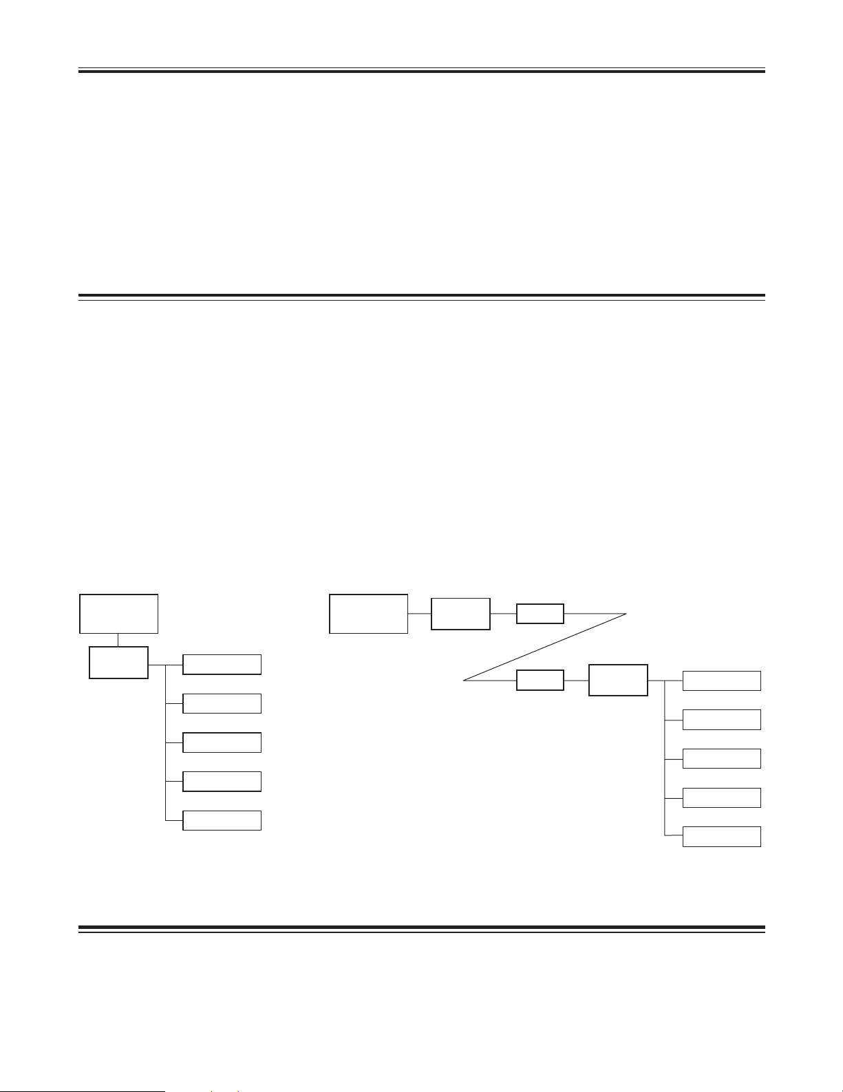
Introduction
O This adapter enables remote control of a pan-tilt head
system using a telephone line.
It is also possible to control a pan-tilt head system
directly, without the use of a telephone line, using the
direct mode.
When control is to be performed via a telephone line, one
of these units (AW-DU600) is required for the system at
both the transmitting and receiving ends.
O When an AW-RP505, AW-RP605 or PC is used as the
controller, it is possible to control a pan-tilt head system
consisting of up to 5 pan-tilt heads. It is possible to select
any one of the pan-tilt heads connected to the system
using the camera switch signals.)
O Control panels which can be used in the transmitting
system
AW-RP301, AW-RP501, AW-RP505 and AW-RP605
O Control panels which can be used in the receiving system
AW-PH300A, AW-PH350, AW-PH500 and AW-PH600
O This adapter can extend only control signals of the
camera and pan-tilt head via a phone line. It is not
possible to transmit video signals.
O Use the same modem at both the transmitting and
receiving ends.
Accessories
Rack mounting adapters . . . . . . . . . . . . . . . . . . . . . . . . . . .2
Joint angle adapters . . . . . . . . . . . . . . . . . . . . . . . . . . . . . .1
Mounting screws (M4) . . . . . . . . . . . . . . . . . . . . . . . . . . . .8
Controller
Telephone line
Controller
Direct mode Transmitting system
Receiving system
Pan-tilt head
system
1
2
3
4
5
1
2
3
4
5
Pan-tilt head
system
Modem
Modem
AW-DU600
AW-DU600
AW-DU600
Page 4
4
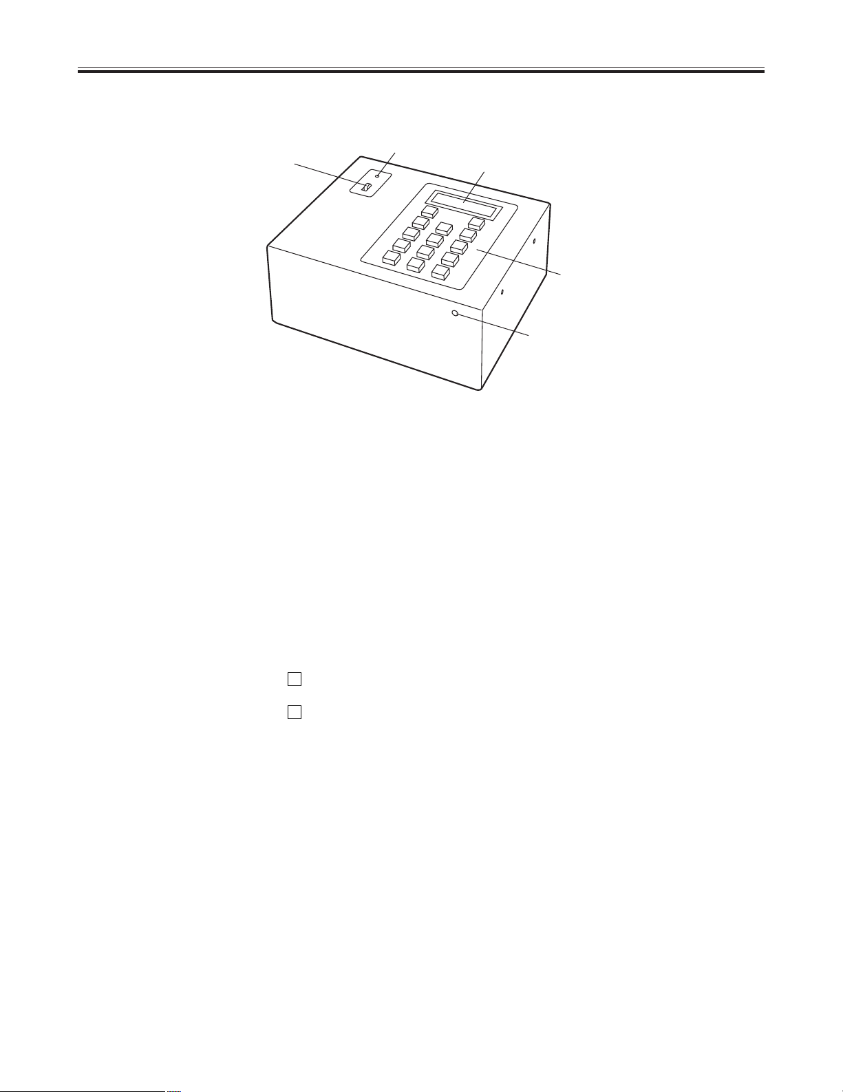
Parts and their functions
$
Control panel
2
1
3
4
5
1 POWER indicator
This lights when power is supplied to the main unit and
the POWER switch is set to ON.
2 POWER switch
This is the unit’s power switch.
3 LCD panel
This displays the current statuses and menu settings.
4 Operating keys
These keys are used for dialing and to perform menu
settings.
These keys are also used to operate the pan-tilt head
system in direct mode.
When any key is operated with the key held down, the
function indicated in red on the key is enabled.
When any key is operated with the key held down, the
function indicated in blue on the key is enabled.
5 LCD contrast control
This is used to adjust the contrast of the LCD panel.
Turning this control clockwise makes the display darker
and turning it counter-clockwise makes it lighter.
(Use a screwdriver to adjust this control.)
#
2
Page 5

5
6 RS-232C CONTROL OUT connectors (P1 to P5)
These connectors are used to connect the pan-tilt head
system controlled with RS-232C.
<Note>
These connectors cannot be used in conjunction with the
RS-422 CONTROL OUT connectors 7.
7 RS-422 CONTROL OUT connectors (P1 to P5)
These connectors are used to connect the pan-tilt head
system controlled with RS-422.
<Note>
These connectors cannot be used in conjunction with the
RS-232C CONTROL OUT connectors 6.
8 TO MODEM connector
This is used to connect the modem.
Connect this connector to the RS-232C connector on the
modem using the RS-232C cable provided with the
modem.
9 TO RCB/PC connector
This is used to connect the WV-CB700A RCB (remote
control box). When the RCB is connected, the control
signals input to the CAMERA CONTROL IN connector <
are disabled.
If the WV-CB700A is connected to the control panel (AWRP301, AW-RP501 or AW-RP505), operation of the IRIS
control on the control panel takes precedence.
Also, if a PC is connected when the adapter is in direct
mode, it is possible to control a pan-tilt head system.
: PAN/TILT CONTROL IN connector
This is used to connect the controller.
When an AW-RP301, AW-RP501 or AW-RP505 is being
used, connect it to the PAN/TILT CONTROL OUT
connector.
When an AW-RP605 is being used, connect it to the
EXTERNAL CONTROL OUT connector on the main unit.
<Note>
An AW-RP605 cannot be used for control in direct mode.
; Control panel selector switch
This is switched according to the control panel
connected.
A: AW-RP605
B: AW-RP301,AW-RP501,AW-RP505, and WV-CB700A
< CAMERA CONTROL IN connector
When an AW-RP501 or AW-RP505 is being used as the
controller, connect it to the CAMERA CONTROL OUT
connector on the control panel.
= GND connector
This is connected to the GND earth to prevent
malfunction caused by external noise.
> DC 12V IN connector
This is the power input connector and is used to connect
the AW-PS301.
? Cable clamp
This is provided for the AW-PS301 cable to prevent the
cable from being pulled out.
Parts and their functions
$
Rear panel
RS-232C CONTROL OUT
P5 P4 P3 P2 P1
P5 P4 P3 P2 PAN/TILT
CONTROL IN
CAMERA
CONTROL IN
GND
DC 12V IN
TO RCB/PC
A
B
P1
TO CAMERA & PAN/TILT HEAD TO MODEM
RS-422 CONTROL OUT
TO CAMERA & PAN/TILT HEAD
TO CONTROL PANEL
6
89
7
:; <
OUT PUT
INPUT
=
>
?
Page 6
6
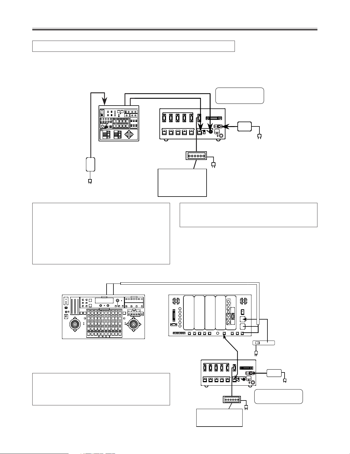
Connections
Transmitting system connections
Connect the control panel
When an AW-RP605 is used
Turn off the power of all components before proceeding with the connections.
OWhen an AW-RP301 or AW-RP501 is being used,
connect the receiving pan-tilt head system to the P1
CONTROL OUT connector.
OWhen an AW-RP505 or AW-RP605 is being used, it is
possible to select either P1, P2, P3, P4 or P5 for the
connected pan-tilt head system using the CONTROL
button on the controller.
OWhen an AW-RP301, AW-RP501 or AW-RP505 is
being used as the controller, an AW-PH350 can not be
used as the pan-tilt head.
Version 45 or higher of the software must be installed in
the AW-RP605.
Consult with your local dealer to check which software
version is currently installed.
Telephone line
Modem
AW-DU600
AW-PS301
Coaxial cable
(5C-2V)
10Base-T cable
RS-232C cable
AW-PS301
Control
panel
Telephone line
Modem
AW-DU600
AC adapter
AW-PS505
AC adapter
AW-PS301
10Base-T cable
AW-RP605
Control panel
AW-RP605
Main unit
Set the control panel
selector switch to A.
Set the control panel
selector switch to B.
Page 7

7
Connections
Dial Up Adapter settings
1 Set this adapter to transmit mode.
Press the key ( i ) to open
the menu settings.
When “Menu-1 Function” appears on the LCD panel,
use the ! # keys and select
Tx (transmit mode).
STOPSTART
START
2
MENU+
2 Select the telephone line.
Press the key ( i ) to change
the menu setting item.
When “Menu-2 Modulate” appears on the LCD panel,
use the ! # keys and select
Tone or Pulse according to the telephone line to be
used.
STOPSTART
START
2
MENU+
4 Set whether or not to turn the power of the pan-tilt
head system off when the telephone line is cut.
Press the key ( i ) to change
the menu setting item.
“Menu-7 Pw-Off” appears on the LCD panel.
Select “Yes” if the power of the camera/pan-tilt head
is to be turned off when the telephone line is cut.
Select “No” if the power of the camera/pan-tilt head is
not to be turned off when the telephone line is cut.
START
2
MENU+
3 Set this adapter to switch to an external line via a
PBX (private branch exchange).
Press the key ( i ) to change
the menu setting item.
When “Menu-3 PBX” appears on the LCD panel, use
the ! # keys and set the
external line selector number to 0 or 9.
Select “None” if a PBX is not to be used.
STOPSTART
START
2
MENU+
Menuj 1 Function
Tx Rx Direct
Menuj 3 PBX
None 0 and 9 and
Menuj 7 Pw-Off
Yes No
Menuj 2 Modulate
Tone Pulse
Transmitting system connection procedure
1.
Connect the AW-PS301 AC adapter to the DC 12V IN
connector on this adapter.
2.
Set the control panel selector switch on this adapter.
Set it to A when using an AW-RP605.
Set it to B when using an AW-RP301, 501, 505, or WVCB700A.
5.
Connect the TO MODEM connector to the RS-232C
connector on the modem using the RS-232C cable
provided with the modem.
6.
Set the power switch on the AW-DU600 to ON.
1: Press Start
1:
jj jj jj
If the modem is not connected correctly, [---] will appear
on the LCD panel.
<Note>
Set the AW-RP605 setting menu (EXT CONTROL
OUT) to ON.
9.
Set the power switch on the modem to ON.
“Press Start” appears on the LCD panel.
7.
Connect the telephone line to the line input jack on the
modem.
8.
3.
Connect the PAN/TILT CONTROL OUT connector on
the control panel to the PAN/TILT CONTROL IN
connector on this adapter using a 10 BASE-T
(equivalent to UTP category 5) straight cable.]
With the AW-RP605, use the EXTERNAL CONTROL
OUT connector.
The connection distance can be extended up to 500
meters.
4.
Connect the CAMERA CONTROL OUT connector on
the control panel to the CAMERA CONTROL IN
connector on this adapter using a coaxial cable
(equivalent to 5C-2V).
This connection is not possible with AW-RP301 and
AW-RP605 control panels as they are not equipped with
a CAMERA CONTROL OUT connector.
The connection distance can be extended up to 500
meters.
When the settings are completed, press the
key ( i ) once again to exit the menu
settings.
START
2
MENU+
Page 8
8
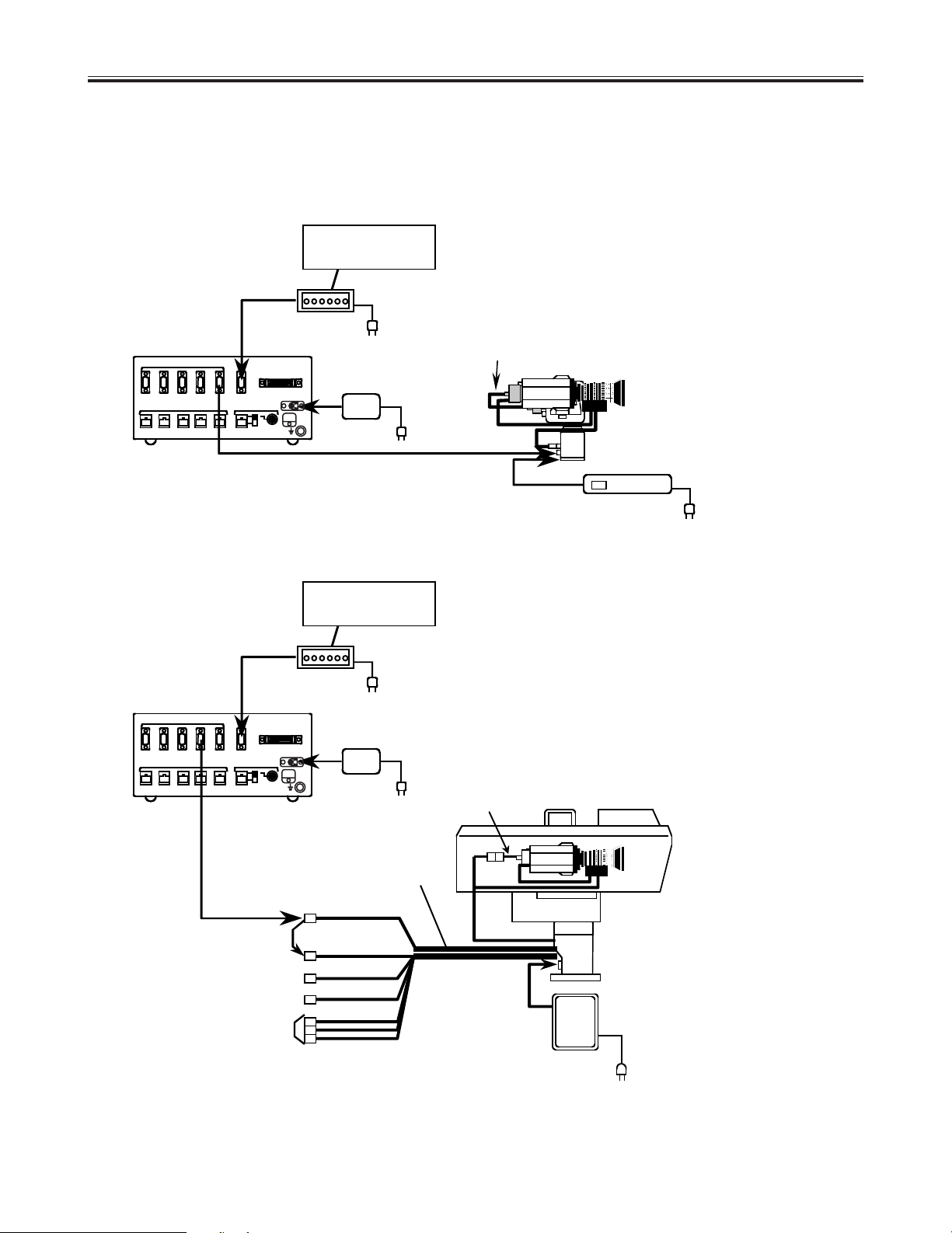
Receiving system connections
Connections
$ Connect the pan-tilt head system to the RS-232C CONTROL OUT connector:
When an AW-PH300A is used and the connection distance is 10 m or less:
When an AW-PH600 is used:
Telephone line
Telephone line
Modem
Modem
AW-DU600
AW-DU600
AW-PS301
AW-PS301
AW-PS600
P-T CONTROL
AW-CA50D15 (component)
AW-CA50A15 (composite)
AW-CA24U10
AW-CA16U10
CAMERA
CONTROL
G/L video (BNC cable)
Video (BNC cable)
COMPONENT
AW-CA50A15
AW-PH300A
AW-CH600
AW-PH600
AW-PS300
AW-CA28T9
Convertible camera
<Note>
Refer to the Operating Instructions of the AW-PH600 for details on how to perform the connections for the AW-PH600.
Page 9

9
Connections
$ Connect the pan-tilt head system to the RS-422 CONTROL OUT connector:
Use the RS-422 connector when the AW-PH350 is to be used as the pan-tilt head or when the connection distance
between this adapter and the pan-tilt head is to exceed 10 m.
When an AW-PH350 is used:
When an AW-PH300A is used and the connection distance is more than 10 m:
Telephone line
Modem
AW-DU600
AW-PS301
Convertible camera
Convertible camera
AW-PH350
AW-PS300
10 Base-T cable
10 Base-T cable
Telephone line
Modem
AW-DU600
AW-PS301
AW-CA50A15
AW-PH300A
AW-PS300
AC adapter
AW-CA28T9
RS-232C/RS-422
converter
AW-CA50C29 (component)
AW-CA50T29 (composite)
Page 10

10
Connections
When an AW-PH600 is used and the connection distance is more than 10 m:
Telephone line
Modem
AW-DU600
AW-PS301
AW-PS600
P-T CONTROL
CAMERA
CONTROL
G/L video (BNC cable)
Video (BNC cable)
COMPONENT
AW-CH600
AW-PH600
RS-232C/RS-422
converter
10 Base-T
cable
AC adapter
AW-CA50D15 (component)
AW-CA50A15 (composite)
AW-CA24U10
AW-CA16U10
<Note>
Refer to the Operating Instructions of the AW-PH600 for details on how to perform the connections for the
AW-PH600.
Page 11

11
Connections
Menuj 1 Function
Tx Rx Direct
Menuj 5 Outputj 1
RSj 232C RSj 422
When the settings are completed, press the
key ( i ) once again to exit the menu
settings.
START
2
MENU+
Receiving system connection procedure
1.
Connect the AW-PS301 AC adapter to the DC 12V IN
connector on this adapter.
3.
Connect the telephone line to the line input jack on the
modem.
5.
Set the power switch on the AW-DU600 to ON.
7.
Set the power switch on the modem and the pan-tilt
head to ON.
8.
“OK” appears on the LCD panel.
6.
Dial Up Adapter settings
1 Set this adapter to receive mode.
Press the key ( i ) to open
the menu settings.
When “Menu-1 Function” appears on the LCD panel,
use the ! # keys and select
Rx (receive mode).
STOPSTART
START
2
MENU+
2 Select the pan-tilt head system control.
Press the key ( i ) to change
the menu setting item.
When “Menu-5 Output-1” appears on the LCD panel,
use the ! # keys and select
RS-2332C or RS-422 according to operating
conditions.
STOPSTART
START
2
MENU+
4.
Connect the pan-tilt head to this adapter.
O If the connection distance between this adapter and
the AW-PH300A pan-tilt-head is 10 m or less, use
the AW-CA28T9 (10 m) cable to connect the RS232C CONTROL OUT connector on this adapter to
the P/T CONTROL IN connector on the AW-PH300A.
O If the connection distance between this adapter and
the AW-PH300A pan-tilt-head is more than 10 m, use
an RS-232C/RS-422 converter between the RS-422
CONTROL OUT connector on this adapter to the P/T
CONTROL IN connector on the AW-PH300A when
performing the connection.
O When the AW-PH350 pan-tilt-head is used, use a 10
BASE-T cable to connect the RS-422 CONTROL
OUT connector on this adapter to the CONTROL IN
IP/RP connector on the AW-PH350.
When an AW-RP301 or AW-RP501 is used as the
controller, connect the pan-tilt head to the P1
CONTROL OUT connector on this adapter.
2.
Connect the TO MODEM connector to the RS-232C
connector on the modem using the RS-232C cable
provided with the modem.
Mode : Receiver
OK
Mode : Receiver
jj jj jj
If the modem is not connected correctly, [---] will appear
on the LCD panel.
Page 12

12
Connections
0123456789
1: Press Start
Making a call
Make a call from the AW-DU600 of the transmitting
system.
2.
Use the number keys on this adapter to enter the
desired number.
The telephone number entered appears on the top
section of the LCD panel.
<Note>
While the telephone line is being connected, none of the
operating keys on the adapters will function except for
the STOP key on the transmitting side.
1.
Turn on the power to all units.
3.
After entering the telephone number, press the
START key.
When the connection is initiated, “Calling” appears on
the LCD panel.
When the connection is established, “Connect” appears
on the LCD panel and control of the pan-tilt head
system from the control panel is possible.
<Note>
The message appearing on the LCD panel may differ,
depending on the modem used.
4.
Control the pan-tilt head system from the control
panel.
When an AW-RP605 is being used as the control panel,
set the OPERATE switch to ON to control the pan-tilt
head system.
<Note>
OWhen an AW-RP505 or AW-RP605 is being used as
the control panel, it is possible to switch the receiving
pan-tilt head system using the CONTROL button on
the control panel.
OIf the OPERATE switch on the AJ-RP605 is set to ON
before the telephone line is connected, “NO
CONNECT” is displayed on the LCD panel.
5.
After control of the pan-tilt head is completed, press the
STOP key.
“Hang Up” appears on the LCD display and the
telephone line is cut.
Once the line is cut, “Press Start” appears on the LCD
panel.
When ON has been selected for the “Menu-7 Pw-Off”
setting, the power to the pan-tilt head will turn off at the
same time as the telephone line is cut. When OFF has
been selected for the “Menu-7 Pw-Off” setting, the
power to the pan-tilt head will remain on when the
telephone line is cut.
<Note>
If the POWER switch or OPERATE switch on the
control panel is set to OFF before the telephone line is
cut, the power to the pan-tilt head will turn off regardless
of the “Menu-7 Pw-Off” setting.
If the wrong number is entered by mistake, press the
DELETE key ( i ) to delete 1 digit at a time,
starting from the number entered last. Press the CLEAR
key ( i ) to delete the whole number at
once.
START#
0#
!Telephone number entered
Page 13

13
Connections
$ Direct mode
Control the pan-tilt head system directly using this adapter:
1.
AW-DU600
AW-PS301
AW-CA50T29 (composite)
AW-CA50C29 (component)
AW-PH350
AW-PS300
10 Base-T cable
Convertible camera
Page 14

14
Connections
Connection procedure
2(:): Up
8(;): Down
4(!): Left
6(#): Right
1 (TELE): Zoom in
7 (WIDE): Zoom out
3 (FAR): Focus (long-distance)
9 (NEAR): Focus (close-up)
5 (BAR): Color bar output
0 (CAM): Camera thru output
3 Select the pan-tilt head system to be controlled.
Press the key ( i ) to change
the menu setting item.
When “Menu-6 Output-2” appears on the LCD panel,
use the ! # keys and select
P1, P2, P3, P4 or P5.
STOPSTART
START
2
MENU+
When the settings are completed, press the
key ( i ) once again to exit the menu
settings.
START
2
MENU+
START
1M12
M2
0
DEL
CAM
5
M5
TELE
3
M3
FAR
78
WIDE
9
NEAR
4
M4
MENU
CLEAR
STOP
MENU
RECALL
6
BAR
4.
When the settings are completed, turn the power of the
AW-DU600 off and then back on again.
The power of the pan-tilt-head system turns on and
operation is possible.
5.
The pan-tilt head system can be controlled in the
following ways using the operating keys on this adapter.
Menuj 6 Output-2
P1 P2 P3 P4 P5
2 Set the CONTROL OUT connector according to the
type of pan-tilt connected and the connection
distance.
Press the key ( i ) to change
the menu setting item.
When “Menu-5 Output-1” appears on the LCD panel,
use the ! # keys and select
RS-2332C or RS-422 according to the pan-tilt head
system to be connected.
STOPSTART
START
2
MENU+
1.
Connect the pan-tilt head system to the CONTROL
OUT connector on this adapter.
2.
Turn on the power to this adapter and the pan-tilt head
system.
3.
Dial Up Adapter settings
1 Set this adapter to direct mode.
Press the key ( i ) to open
the menu settings.
When “Menu-1 Function” appears on the LCD panel,
use the ! # keys and select
Direct (direct mode).
STOPSTART
START
2
MENU+
Menuj 1 Function
Tx Rx Direct
Menuj 5 Output-1
RSj 232C RSj 422
Page 15

15
Connections
AW-DU600
Control
panel
AW-PS301
AW-PS301
AW-CA50T29
AW-PH350
AW-PS300
10 Base-T cable
Convertible camera
AW-DU600
AW-PS301
PC
AW-CA50T29
AW-CA50T9
AW-PH350
AW-PS300
10 Base-T cable
Convertible camera
Control the pan-tilt head system using a control panel or PC:
2.
Coaxial cable (5C-2V)
10Base-T cable
<Note>
AW-RP605 cannot be used as the control panel with direct mode.
Page 16

16
Connections
2 Select the connector for input of control signals from
the controller.
Press the key ( i ) to change
the menu setting item.
“Menu-4 Input” appears on the LCD panel.
Select the CONTROL OUT connector to be used
using the ! # keys.
When control is to be performed from a control panel,
select RS-422 and select RS-232C when it is to be
performed from a PC.
STOPSTART
START
2
MENU+
When the settings are completed, press the
key ( i ) once again to exit the menu
settings.
START
2
MENU+
Menuj 4 Input
RSj 232C RSj 422
3 Set the CONTROL OUT connector according to the
type of pan-tilt connected and the connection
distance.
Press the key ( i ) to change
the menu setting item.
When “Menu-5 Output-1” appears on the LCD panel,
use the ! # keys and select
RS-232C or RS-422 according to the pan-tilt head
system to be connected.
STOPSTART
START
2
MENU+
7.
6.
Set the power switch on the pan-tilt head to ON.
8.
Set the POWER switch on the control panel to ON to
control the pan-tilt head system. When an AW-RP505 is
being used as the control panel, select the pan-tilt head
system using the CONTROL button on the control
panel.
9.
When the POWER switch on the control panel is set to
OFF after control of the pan-tilt head is completed, the
power of pan-tilt head system will turn off.
Connection procedure
1.
Connect the AW-PS301 AC adapter to the DC 12V IN
connector on this adapter.
2.
Set the control panel selector switch on this adapter to
B.
5.
Dial Up Adapter settings
1 Set this adapter to direct mode.
Press the key ( i ) to open
the menu settings.
When “Menu-1 Function” appears on the LCD panel,
use the ! # keys and select
Direct (direct mode).
STOPSTART
START
2
MENU+
Menuj 1 Function
Tx Rx Direct
Menuj 5 Output-1
RSj 232C RSj 422
3.
1 Connect the PAN/TILT CONTROL OUT connector
on the control panel to the PAN/TILT CONTROL IN
connector on this adapter using a 10 BASE-T
(equivalent to UTP category 5) straight cable.
The connection distance can be extended up to 500
meters.
2 Connect the CAMERA CONTROL OUT connector on
the control panel to the CAMERA CONTROL IN
connector on this adapter using a coaxial cable
(equivalent to 5C-2V).
The connection distance can be extended up to 500
meters.
<Note>
This connection is not possible with the AW-RP301
control panel as it is not equipped with a CAMERA
CONTROL OUT connector.
3 When a PC is used as the control panel, connect it to
the TO RCB/PC connector on this adapter.
4.
Set the power switch on this adapter to ON.
Page 17

17
START
1
M1
2
M2
0
DEL
CAM
5
M5
TELE
3
M3
FAR
78
WIDE
9
NEAR
4
M4
MENU
CLEAR
STOP
MENU
RECALL
6
BAR
Menu settings
O Press the key ( i ) and the first
menu item will appear on the LCD.
O Press the key ( i ) while a menu
item is displayed on the LCD and the display will move to
the next item.
O Press the key ( i ) again and the
last menu item will appear on the LCD.
O Press the key ( i ) while a menu
item is displayed on the LCD and the display will move to
the previous item.
O Use the ! # keys to select the
setting for each menu item.
STOPSTART
STOP
2
MENUj
START
2
MENU+
START
2
MENU+
START
2
MENU+
$ How to perform menu settings
$ Menu items
Menu-1 Function
(Initial setting: Tx)
Dial up adapter mode settings
Telephone line settings
This is when the telephone line to be used is a tone line.Tone
Pulse
External line transmission number settings
None
0 and
9 and
This is when the telephone line to be used is a pulse line.
This is for when an external line transmission number is not required.
This is for when 0 is to be transmitted via a PBX.
This is for when 9 is to be transmitted via a PBX.
This is for when this adapter is to be used as the transmitting system.Tx
Rx
Direct
This is for when this adapter is to be used as the receiving system.
This is for when this adapter is to be used in direct mode (i.e. when a
telephone line is not to be used).
Menu-2 Modulate
(Initial setting: Tone)
Menu-3 PBX
(Initial setting: None)
The following items are only displayed when this adapter is in Tx mode.
Yes
No
Power control setting for the pan-tilt head system when the telephone line is cut
The power of the pan-tilt head system turns off when the line is cut.
The power of the pan-tilt head system does not turn off when the line is cut.
Menu-7 Pw-off
(Initial setting: Yes)
Page 18

18
Menu settings
$ Dial memory
Menu-6 Output-2
(Initial setting: P1)
This setting selects which pan-tilt head system is to be controlled by this adapter when this
adapter is in Direct mode.
The pan-tilt head system connected to the RS-232C or RS-422 P1 connector is
controlled.
P1
P2
P3
P4
P5
The pan-tilt head system connected to the RS-232C or RS-422 P2 connector is
controlled.
The pan-tilt head system connected to the RS-232C or RS-422 P3 connector is
controlled.
The pan-tilt head system connected to the RS-232C or RS-422 P4 connector is
controlled.
The pan-tilt head system connected to the RS-232C or RS-422 P5 connector is
controlled.
This adapter’s dial memory function enables up to 5 specific
telephone numbers to be stored.
O Registering a telephone number
1. Enter the number using the operating keys on this
adapter.
2. While pressing the key, press one of the dial memory
registration keys from (M1) through (M5) into
which the number is to be entered.
3. “Writing Memory 2” (2 is the dial memory number)
appears on the LCD panel and the telephone number is
stored.
51
#
O Using a dial memory to make a call
1. Press the key ( i ).
2. The dial memory number (M1 to M5) entered appears on
the LCD panel.
If a telephone numbers has not been registered for the
dial memory number, the LCD panel display will be blank.
3. Each time the key ( i ) is
pressed, the dial memory number is switched.
4. Press the key to initiate the connection.
START
STOP#RECALL
STOP#RECALL
This setting selects which connector is to be used for the controller when this adapter is in Direct mode.
TO RCB/PC connector (PC used for control)
PAN/TILT CONTROL IN connector (control panel used for control)
RS-232C
RS-422
This setting selects which connectors are to be used for the pan-tilt head systems.
The RS-232C CONTROL OUT connectors are used.
The RS-422 connectors cannot be used in conjunction with these
connectors.
The RS-422 CONTROL OUT connectors are used.
The RS-232C connectors cannot be used in conjunction with these
connectors.
RS-232C
RS-422
Menu-4 Input
(Initial setting:RS-232C)
Menu-5 Output-1
(Initial setting: RS-422)
The following items are only displayed when this adapter is in Direct mode
The following item is only displayed when this adapter is in Rx mode or Direct mode
O Erasing a dial memory
1. Press the key ( i ) to erase the
number displayed on the LCD panel.
2. While pressing the key, press one of the dial memory
registration keys from (M1) through (M5) which is
to be erased.
3. “Writing Memory 2” (2 is the dial memory number)
appears on the LCD panel and the telephone number is
erased.
51
#
START#CLEAR
Page 19

19
Attaching the rack mounting adapters
Changing the position of the rear panel
To install the adapter in a rack, use the rack mounting adapters and four of the mounting screws (M4) supplied.
1. Remove the three screws from the bottom panel and
remove the blank panel.
2. Remove the three screws from the rear panel and
remove the rear panel.
3. Use the three screws to firmly secure the rear panel
where the blank panel was removed from the bottom
panel.
Take care not to catch the internal wiring when reattaching the panels.
RS-232C CONTROL OUT
P5 P4 P3 P2 P1
P5 P4 P3 P2 PAN/TILT
CONTROL IN
CAMERA
CONTROL IN
GND
DC 12V IN
TO RCB/PC
A
B
P1
TO CAMERA & PAN/TILT HEAD TO MODEM
RS-422 CONTROL OUT
TO CAMERA & PAN/TILT HEAD
TO CONTROL PANEL
OUT PUT
IN PUT
4. Use the three screws to firmly secure the blank panel
where the rear panel was removed.
RS-232C CONTROL OUT
P5 P4 P3 P2 P1
P5 P4 P3 P2 PAN/TILT
CONTROL IN
CAMERA
CONTROL IN
GND
DC 12V IN
TO RCB/PC
A
B
P1
TO CAMERA & PAN/TILT HEAD TO MODEM
RS-422 CONTROL OUT
TO CAMERA & PAN/TILT HEAD
TO CONTROL PANEL
OUT PUT
IN PUT
Screws
Screws
Screws
Screws
Blank panel
Blank panel
Rack mounting adapter
Screw
Page 20

20
Attaching the joint angle adapter
To attach the adapter to the controller, use the joint angle adapter, rack mounting adapter and mounting screws (M4 x 8)
supplied.
Rack mounting adapter
Screw
Joint angle adapters
Page 21

21
Specifications
indicates safety information
Power supply: DC 10.8V to DC 16V
Power consumption: 5 W
Permissible temperatures
Storage: j20˚C to 60˚C
Operating: j10˚C to 45˚C
Standard: i5˚C to 35˚C
Permissible humidity
Storage: 30% to 90% (without condensation)
Weight:
3.7 lb (1.7 kg)
Dimensions (WkHkD):
8-1/4k3-3/8k6-7/8 inch (210k86k176
mm)
Controllers supported
AW-RP301, AW-RP501, AW-RP505, AW-RP605 and
WV-CB700A
Pan-tilt heads supported
AW-PH300A, AW-PH350 (this model can only be used
with the AW-RP605), AW-PH500 and AW-PH600
Cameras supported
AW-E300, AW-E300A, AW-E600, AW-E800A, AW-E800
Input connectors
DC12V IN socket
Connects the AW-PS301
TO RCB/PC
AW-CA50T10 (when a WV-CB700A is connected)
AW-CA50T9 (when a PC is connected)
PAN/TILT CONTROL IN
RJ45
Connects to PAN/TILT CONTROL OUT on the
remote control panel
10BaseT straight cable (UTP category 5), max. 500
meters
CAMERA CONTROL IN
BNC
Connects to CAMERA CONTROL OUT on the
remote control panel
BNC cable (5C-2V), max. 500 meters
Output connectors:
RS-232C CONTROL OUT
TO CAMERA & PAN/TILT HEAD
D-sub, 9-pink5 (connect to pan-tilt head)
RS-422 CONTROL OUT
TO CAMERA & PAN/TILT HEAD
RJ45k5 (connect to pan-tilt head)
10BaseT straight cable (UTP category 5), max. 1000 m
I/O connector
TO MODEM
D-sub, 9-pin k1 (connects to analog modem)
Other
A/B selector switch
Control panel selector switch
A: AW-RP605
B: AW-RP301, AW-RP501, AW-RP505 and WV-
CB700A
Page 22

22
Page 23

23
Page 24

PANASONIC BROADCAST & TELEVISION SYSTEMS COMPANY
UNIT COMPANY OF MATSUSHITA ELECTRIC CORPORATION OF AMERICA
Executive Office:
One Panasonic Way 4E-7, Secaucus, NJ 07094 (201) 348-7000
EASTERN ZONE:
One Panasonic Way 4E-7, Secaucus, NJ 07094 (201) 348-7621
Southeast Region:
1225 Northbrook Parkway, Ste 1-160, Suwanee, GA 30024 (770) 338-6835
Central Region:
1707 N Randall Road E1-C-1, Elgin, IL 60123 (847) 468-5200
WESTERN ZONE:
3330 Cahuenga Blvd W., Los Angeles, CA 90068 (323) 436-3500
Government Marketing Department:
52 West Gude Drive, Rockville, MD 20850 (301) 738-3840
Broadcast PARTS INFORMATION & ORDERING:
9:00 a.m. – 5:00 p.m. (EST) (800) 334-4881/24 Hr. Fax (800) 334-4880
Emergency after hour parts orders (800) 334-4881
TECHNICAL SUPPORT:
Emergency 24 Hour Service (800) 222-0741
Panasonic Canada Inc.
5770 Ambler Drive, Mississauga, Ontario L4W 2T3 (905) 624-5010
Panasonic de Mexico S.A. de C.V.
Av angel Urraza Num. 1209 Col. de Valle 03100 Mexico, D.F. (52) 1 951 2127
Panasonic Sales Company
Division of Matsushita Electric of Puerto Rico Inc.
San Gabriel Industrial Park, 65th Infantry Ave., Km. 9.5, Carolina, Puerto Rico 00630 (787) 750-4300
F0602Y
@
Printed in Japan
VQT9129
P
 Loading...