

Page 1
Panasonic®
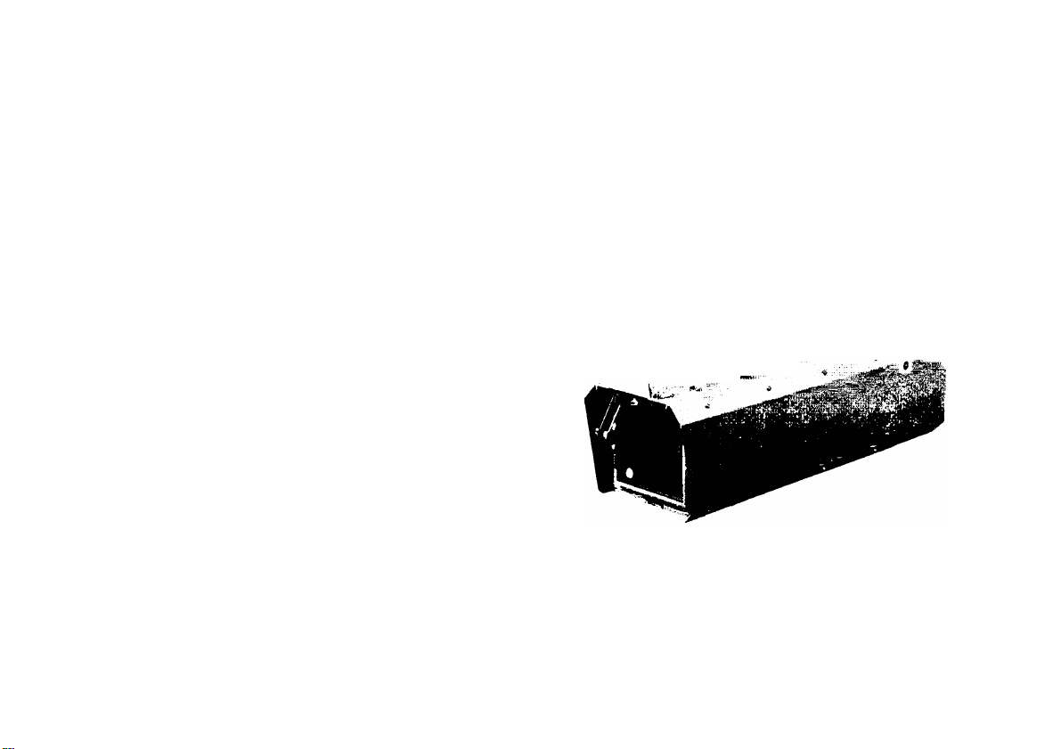
Outdoor Camera Housing
Model No. AW-CH600
Operating
Instructions
.'-1
Before attempting to connect or operate this product,
please read these instructions completely
and save this manual for future use.
Page 2
CAUTION
RISK DF electric SHOCK
A
CAUTION
TO REDUCE THE RISK OF ELECTRIC SHOCK, 00
NOT REMOVE COVER (OR BACK) NO USER SER
VICEABLE PARTS INSIDE
REFER SERVICING TO QUALIFIED SERVICE PER
SONNEL
The lightning flash with arrowhsad symbnl, Within an equilateral triangle, is
intended ta alert the user to the pres
ence nf uninsulated "dangerous voltage"
within the product's enclosure that may
A
SA 1SB5
be of sufficient magnitude to ccnstitute a
risk of electric shock to persons
The exclamation point within an equilat
eral triangle IS intended to alert the user
to the presence □[ important operating
and maintenance (servicing) instructions
m the literature accompanying the appli
ance
--------------------------------------------------------
NÜTE This equipment has been tested and found to com
ply with the limits for a Class A digital device, pursuant tc
part 15 of the FCC Rules These limits are designed to pro
vide reasonable protection against harmful interference
when Ihe equipment is operated in a commercial environ
ment This equipment generates, uses, and can radiate
radio frequency energy and, if not installed and used in
accordance with the instruction manual, may cause harmful
interference to radio communications Dperalion of this
equipment in a residential area is likely to cause harmful
interiference in which case Ihe user will be required to correcl the interference at his own expense
------------------------------------
This Class A digital apparatus complies with Canadian
ICES-D03
Get appareil numérique de la classe A est conforme a la
norme NMB-Ü03 du Canada
The information marking of this product may be found on the
bottom of the product
The serial number of this product may he found on the bcltom of the product
Ycu should note the serial number of this product in the
space provided and retain this bock as a permanent record
□f ycur purchase tc aid identification in the event of theft
Mcdel No
Serial No
-------------------------------------------
----------------------
For CANADA-
For U s A-
-2-
Page 3

CONTENTS
WARNING/CAUTION FOR SAFETY....................................................................................................................................... 4
PREFACE ............................................................................................................................................................................... 5
MAJOR OPERATING CONTROLS AND THEIR FUNCTIONS............................................................................................... 6
MOUNTING ............................................................................................................................................................................ 9
■ Caution...............................................................................................................................................................................9
■ Camera Mounting ............................................................................................................................................................. 9
■ Mounting to Pan/Tilt Head............................................................................................................................................... 11
CONNECTION ...................................................................................................................................................................... 12
■ Connection to Camera.................................................................................................................................................... 12
■ Connecting Cables from the Housing to PanYHIt Head ................................................................................................ 13
APPEARANCE ..................................................................................................................................................................... 14
SPECIFICATIONS ................................................................................................................................................................ 15
STANDARD ACCESSORIES ............................................................................................................................................... 15
-3-
Page 4

WARNING/CAUTION FOR SAFETY
A
WARNING
- Refer all servicing to qualified personnel
To reduce the risk of electric shock, don't remove
cover or oack, unless /ou are a qualified personnel
Refer all mountings, connections, servicing to quali
fied service personnel
■ No water or moisture inside
Do not let water nr moisture into the product, or
expose It to moisture, to prevent a fire and electric
shock
If you see smoke or smell an odor from the product
if water or other foreign matter gets inside, if it is
damaged by dropping or if you find anything
wrong with It, immediately stop using it
Do not disassemble or modify the product to
prevent a fire and electric shock
A
CAUTION
Install it at a stable place and fasten it securely
The product may fall due to unstable installation,
possibly causing injuries and accidents
Be sure to switch power off before maintenance
□r installation
Otherwise, there is the danger of fingers caught in
the rotating parts or of other injuries
Do not install this product near any object that
burns easily
In case of using a halogen lamo, installation of it
near such an odject could cause a fire due to the
heat generated by the lamp
-4-
Page 5

PREFACE
The AW-CHGOO is an □uldaor camera housing for
the Panasonic series of convertible cameras An
outdoor pan/tilt head system can he built by com
bining It with the outdoor pan/tilt head AW-PH600
and AC adapter AW-PS600
The camera housing has a wiper and defroster
The inside temperature is controlled by a heater and
an exhaust fan
This product conforms to the waterproof standard
IPX3
-5-
Page 6

MAJOR OPERATING CONTROLS AND THEIR FUNCTIONS
-6-
Page 7

о Wiper Unit
Used to Wipe nlf waterdrops during or after a rain
The wiper operates when the WIP switch on the
control panel (AW-RP3D1 or AW-HP5D1, for exam
ple) IS pressed cn
О Wiper Blade
Replace the wiper blade when it can no longer wipe
off waterdrops well
How to replace it Raise the blade at the center pull
It up and off, and fit a new blade in its place Alter
replacing the blade check that the two rods hnlding the wiper blade are parallel to the glass surface
(Whenever the wiper blade needs replacement, ask
the store where you purchased the product to do
the job )
8 Camera Housing Handle
Used to carry the camera housing
О Side Cover
Open the side cover when mounting a camera in
the camera housing
О Key Hole
Insert the key (an accessory) into the key hole, and
turn the screw counterclockwise in the hole Then
□ pen the cover by pulling it toward yoursell
Turn the key clockwise to shut the side cover
Nole Keep the key with care
О Air Filler
Air IS taken in through the air filter Replace it when
It IS clogged up The end of fhe air filter can be
seen when the side cover is opened When replac
ing the air filter, remove it from there
(Whenever the air filler needs replacement, ask the
store where you purchased the product to do the
job )
О Exhaust Fan
The fan runs when the internal temperature of the
camera housing rises, provided that the H/F switoh
on the control panel is in the ON position
It has two levels of operation, high and low,
depending on the temperature
О Camera Housing Mounting Screw Holes
Fasten the camera housing to the pan/lilt head with
the two screws (supplied with pan/tilt head)
0 ND/EXT Connector
Connect It to the ND/EXT connector on the pan/till
head (AW-PH600)
-7-
Page 8

QD CAMERA l/F Conneclar
Connect It tn the CAMERA l/F connector on the
pan/tilt head
0 HOUSING l/F Connector
Connect It to the HOUSING l/F connector on the
pan/tilt head
® Defroster
The defroster heater is built in by the process at
vapor deposition It operates when the DEF switch
on the control panel is pressed on, and is turned off
by the thermostatic switch when the temperature
exceeds the preset level
® Side Cover Chain
The chain holds the side cover at about 90° when it
IS opened
Camera Mount
Loosen the camera mount screws, move the cam
era mount to the round hole position remove the
mount, and fix the mount to the camera
To fix the mount to the camera housing, insert the
camera mounting pin into the rail fixed at the farther
end, and insert the pin into the round hale up front,
making sure that the pm is in line with the hole
Hold the lens as close to the defroster glass surface
as possible, and tighten the mount screws
NdIb- With the lens in the WIDE position, watch the
picture from the camera and determine the
position free of wiper shadow )
® Camera Mount Screws
® Camera Housing Control Board
This beard automatically controls the ON/DFF of the
wiper, fan, rubber heater and defroster with control
signals from the control panel
® LENS l/F Connector
Connect It to the lens control cable (for zoom and
focus control)
0 l/F REMOTE Connector
Connect It to the l/F REMOTE connector on the
camera via the camera connecting cable
0 ND/EXT Connector
This connector is used to control the lens ND filter
and extender It is not used if the lens does not
have the ND filter/extender function
Silicon Rubber Heater
This heater is turned on when the internal tempera
ture of the camera housing falls, provided that the
H/F switch on the control panel is in the ON posi
tion
-B-
Page 9

CAUTION
Be sure to keep system power (including the
power of the pan/tilL head and AC adapter)
switched oft during installation and connection
Fix the housing to the pan/tilt head securely so
that It will not be unsteady during pan/tilt or when
the head is still
□ □ not install the camera housing at a place
extremely cold below -SO^C or extremely hot,
over +BD°C tc avoid operation instability
Camera Mounting
Loosen the camera mount screws, move the cam
era mount tc the round hole position, remove the
mount, and (ix the mount tc the camera
In mounting the camera remember that the mount
ing screw and spacer may be used cr net depend
ing on the model
To fix the mount to the camera housing, insert the
camera mounting pm into the rail fixed at the farther
end and insert the pm into the round hcle up front,
making sure that the pin is m line with the hole
Hold the lens as close to the defroster glass surface
as possible, and tighten the mount screws
To use the 33X (3GX) lens, the lens support and
screws (options) are necessary Consult the store
where you purchased the product
Male With the lens in the TELE position watch the
picture from the camera and determine the
position free cf wiper shadow )
After meunting the camera, check that the camera
IS free of play
Camera AW-EBQO
Install the camera with the camera mounting screw
(9 mm)
-3-
Page 10

Camera AW-E300
Use Lhe camera mnunting screw (17 mm) and spac
er (H mm thick)
Camera AE-E600
Use the camera mcuntmg screw (12 mm) and spac
er (4 mm thick)
Tighlsn lhe spacer wilh
Camera mounling screw (12 mm) Tighlen the spacer wilh
Insulaling washer screws
Camera mounl
Mnve the plaslic pin | I |
la lhe spacer 'n r
Spacer (i mm ihick) —^ ^
t
I /0;
Camera mcunlmg adaplnr i [
!'
-ID-
Page 11

Mounting to Pan/Tilt Head
With the tilling arm held horizontal, fit the temporary
mounting boss on the bottom ol the housing into the
groove in the arm, and temporarily fasten the hous
ing from below with the two housing mounting
bolts
Move the camera housing back and forth till it is
well balanced, then fasten it securely
As the stop position depends heavily on the bal
ance of the camera housing, be sure to check the
accuracy of the preset stop positions after tilting
with the picture from the camera
Rough Yardstick for Good Balance (±5' from preset
stop position)
The position of good balance varies depending on
the combination of the camera and lenses
Set the arm scale in line with the housing position
mark (I), referring to the table below
Camera Housing AW-CH600
Camera
AW-E300 AW-LZ14MD55
AW-E600
AW-EGDO CANNON 14X
AW-E600 CANNON 17X
AW-EBOO
AW-EBOO FUJINON 36X
Lens
AW-S14XBMD
AW-LZ17MD9
(A3BX14, SBERD-E20)
Housing Pasilion
1 backward
0
2 backward
5 backward
2 backward
7 backward
-11-
Page 12

CONNECTION
Connection to Camera
The
ND/EXT
connector is used to control the lens
filter/extender Function
Bind and clamp unused connectors and cables, if any so they will not dangle while the pan/tilt head is in use
Select the necessary camera connecting cable from among the optional cables shown below
■ Camera pan/till head cable (for RS-232C, personal computer control)
AW-CA50A15 (for ccmposite video)
AW-CA50D15 (for component video)
■ Pan/tilt head cable (nc RS-232C control)
ND
filter and extender It is not used if the lens does not have the
ND
Page 13

Connecting Cables from the Housing to Pan/Tilt Head
Connect the cables from the bottom of the camera housing to the connectors an the panning head, respectively
-13-
Page 14

APPEARANCE
2Z7 (a-15/16)
m -
1 1 3
4 - 7 / 1 B )
1 1 4
J 4 1 / 2
Unii mm (inch)
S3
S 3
■
t
1
,,L.!=
1
_ _
' ' ■ ^
CO
14-
Page 15

SPECIFICATIONS
Power
Applicable lenses
Heater
Wiper
Defroster
Fan ON/OFF controllable, ON at about 30°C or over
Maximum payload
Working temperature range -20°C to H-BD=C
Ambient humidity 30% to 90%
Dimensions
Weight 10 kg (22 05 lbs)
Finish AV ivory paint (Munsell 7 9Y6 B/D B or approximate)
Weight and dimensions indicated are approximate
Specifications are subject to change
Supplied from pan/till head
AW-LZ14MD55, AW-LZ17MD9 AW-LZ1DMDB, A36x14 5BERD-E2B,
J33ax15B4 1ASSX12
ON/OFF controllable, ON at about 5°C or below
□N/OFF controllable
ON/OFF controllable, OFF at about 40°C or over
ID kg (Camera and lens)
227 (W) X 253 (H) X 720 (D) mm
[B-15/16’ (W) X 9-15/15' (H) X 2B-11/32' (D)]
without notice
SÌlpÀRD ÀeCÈSSiORIES i t
Key 1 pc
Spacer (8 mm thick for AW-E300) 1 pc
Camera mounting screw (17 mm ter AW-E3Q0) 1 pc
Spacer (4 mm thick ferAW-EBDO) 1 pc
Camera mounting screw (12 mm for AW-EGQD) 1 pc
Spacer screw (M4) 4 pcs
Camera mounting screw
(9 mm for AW-EaoO) 1 pc
-15-
Page 16

Panasonic
PANASONIC BROADCAST & DIGITAL SYSTEMS COMPANY
DIVISION OF MATSUSHITA ELECTRIC CORPORATION OF AMERICA
EaecUtlVe OffiCB
3330 Cahusnga Blvd W , Los Angeles, CA 90060 (323) 436-3500
EASTERN ZONE
One Panasonic Way4E'7, Secaucus NJ 07094 (201) 340-7621
Mid-Atlanlic/New England
One Panasonic Way 4E-7, Secaucus, NJ D7G94 (201) 340-7621
Southeasl Region
1225 Northbrook Parkway, Ste 1-160, Suwanee, GA 30024 (770) 330-6035
Central Region
1707 N Randall Road El-C-1, Elgin, IL 60123 (B47) 4B0-52OO
WESTERN ZONE
3330 Cahuenga Blvd W Los Angeles, CA 9DOB0 (323) 436-3500
Dallas Region
6226 Ahington Way, Houston, TX 77000 (713) 002-2726
No CA/Northwesl Region
5070 Stcnendge, #3, Pleasanton, CA 9450H (925) 416-5100
Government Marketing Department
52 WesI Gude Drive, Rockville MD 20050 (301) 730-3040
Panasonic Canada Inc
5770 Ambler Drive, Mississauga Ontario L4W 2T3 (905) 624-5010
Panasonic Sales Company
Division of Matsushita Electric of Puerto Rico Inc
San Gabnel Industrial Park, 65th Infantry Ave , Km 9 5 Carolina, Puerto Rico 00530 (767) 750-4300
Printed in Japan
7J1A427B
F020DY1D90 [d]
 Loading...