

Page 1
Before attempting to connect, operate or adjust this product,
please read these instructions completely.
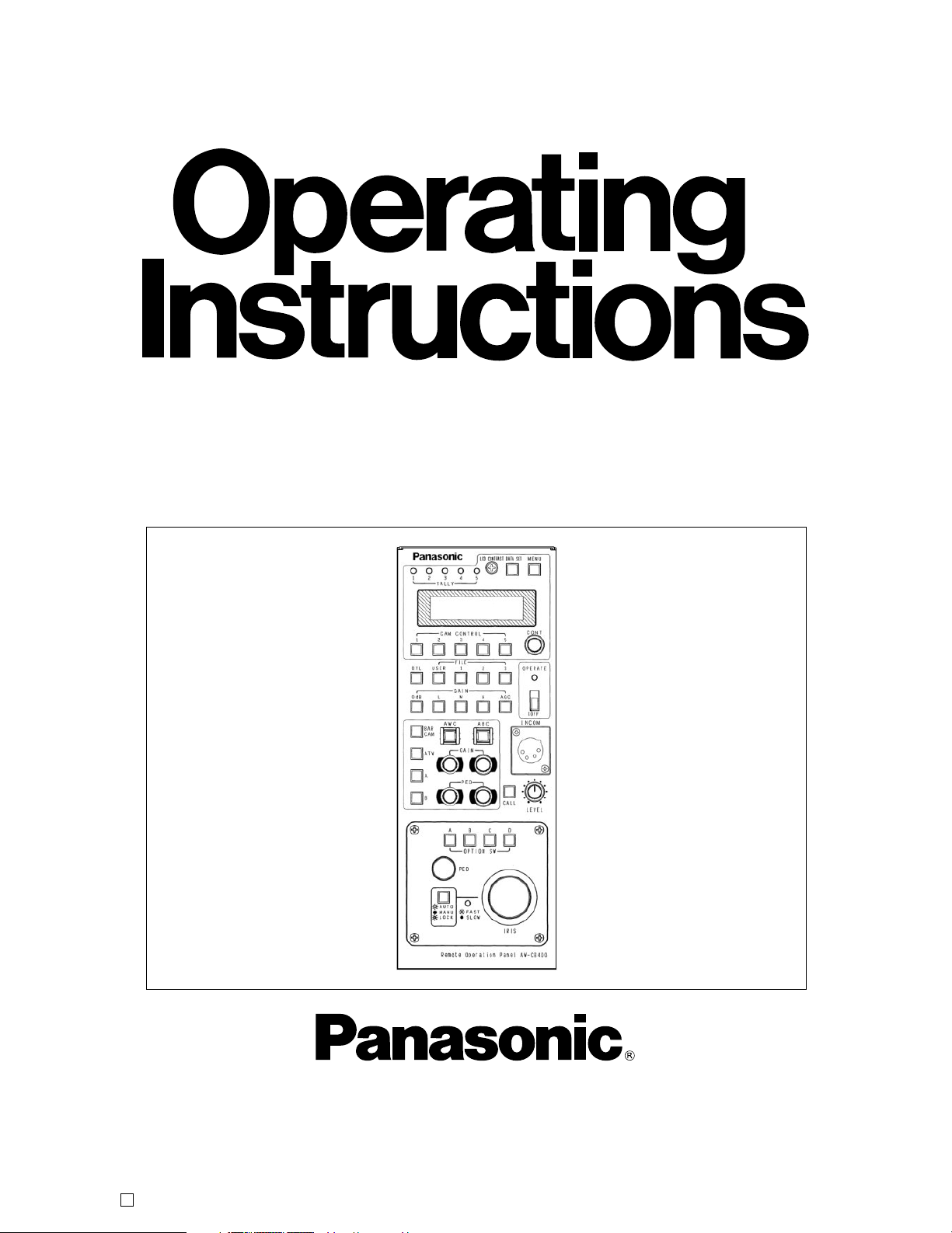
Remote Operation Panel
AW-CB400N
Printed in Japan
F1104S0 VQTB0045
D
Page 2
2
Safety precautions
1 indicates safety information.
CAUTION
RISK OF ELECTRIC SHOCK
DO NOT OPEN
CAUTION: TO REDUCE THE RISK OF ELECTRIC SHOCK,
DO NOT REMOVE COVER (OR BACK).
NO USER SERVICEABLE PARTS INSIDE.
REFER SERVICING TO QUALIFIED SERVICE PERSONNEL.
The lightning flash with arrowhead symbol,
within an equilateral triangle, is intended to
alert the user to the presence of uninsulated
“dangerous voltage” within the product’s
enclosure that may be of sufficient magnitude
to constitute a risk of electric shock to
persons.
The exclamation point within an equilateral
triangle is intended to alert the user to the
presence of important operating and
maintenance (service) instructions in the
literature accompanying the appliance.
WARNING:
TO REDUCE THE RISK OF FIRE, ELECTRIC
SHOCK OR PRODUCT DAMAGE, DO NOT
EXPOSE THIS EQUIPMENT TO RAIN OR
MOISTURE, DRIPPING OR SPLASHING AND
THAT NO OBJECTS FILLED WITH LIQUIDS,
SUCH AS VASES, SHALL BE PLACED ON
THE EQUIPMENT.
This class A digital apparatus complies with
Canadian ICES-003.
Cet appareil numérique de la classe A est
conforme à la norme NMB-003 du Canada.
CAUTION:
TO REDUCE THE RISK OF FIRE OR SHOCK
HAZARD AND ANNOYING INTERFERENCE,
USE ONLY THE RECOMMENDED
ACCESSORIES.
The socket outlet shall be installed near the
equipment and easily accessible or the mains plug or
an appliance coupler shall remain readily operable.
FCC Note:
This device complies with Part 15 of the FCC Rules.
To assure continued compliance follow the attached
installation instructions and do not make any
unauthorized modifications.
This equipment has been tested and found to comply
with the limits for a class A digital device, pursuant to
Part 15 of the FCC Rules. These limits are designed
to provide reasonable protection against harmful
interference when the equipment is operated in a
commercial environment. This equipment generates,
uses, and can radiate radio frequency energy and, if
not installed and used in accordance with the
instruction manual, may cause harmful interference to
radio communications. Operation of this equipment in
a residential area is likely to cause harmful
interference in which case the user will be required to
correct the interference at their own expense.
For CANADA
CAUTION:
DO NOT INSTALL OR PLACE THIS UNIT IN A
BOOKCASE, BUILT-IN CABINET OR ANY
OTHER CONFINED SPACE IN ORDER TO
MAINTAIN ADEQUATE VENTILATION.
ENSURE THAT CURTAINS AND ANY OTHER
MATERIALS DO NOT OBSTRUCT THE
VENTILATION TO PREVENT RISK OF
ELECTRIC SHOCK OR FIRE HAZARD DUE
TO OVERHEATING.
Note:
The rating plate (serial number plate) is on the
bottom of the unit.
WARNING:
TO PREVENT INJURY, THIS APPARATUS
MUST BE SECURELY ATTACHED TO THE
FLOOR/WALL IN ACCORDANCE WITH THE
INSTALLATION INSTRUCTIONS.
A warning that an apparatus with CLASS I
construction shall be connected to a MAINS socket
outlet with a protective earthing connection.
Page 3
3
Safety precautions
1 indicates safety information.
1) Read these instructions.
2) Keep these instructions.
3) Heed all warnings.
4) Follow all instructions.
5) Do not use this apparatus near water.
6) Clean only with dry cloth.
7) Do not block any ventilation openings. Install in
accordance with the manufacturer's instructions.
8) Do not install near any heat sources such as
radiators, heat registers, stoves, or other
apparatus (including amplifiers) that produce heat.
9) Do not defeat the safety purpose of the polarized
or grounding-type plug. A polarized plug has two
blades with one wider than the other. A groundingtype plug has two blades and a third grounding
prong. The wide blade or the third prong are
provided for your safety. If the provided plug does
not fit into your outlet, consult an electrician for
replacement of the obsolete outlet.
10) Protect the power cord form being walked on or
pinched particularly at plugs, convenience
receptacles, and the point where they exit from
the apparatus.
11) Only use attachments/accessories specified by
the manufacturer.
12) Use only with the cart, stand, tripod,
bracket, or table specified by the
manufacturer, or sold with the
apparatus. When a cart is used, use
caution when moving the
cart/apparatus combination to avoid
injury from tip-over.
13) Unplug this apparatus during lightning storms or
when unused for long periods of time.
14) Refer all servicing to qualified service personnel.
Servicing is required when the apparatus has
been damaged in any way, such as power-supply
cord or plug is damaged, liquid has been spilled or
objects have fallen into the apparatus, the
apparatus has been exposed to rain or moisture,
does not operate normally, or has been dropped.
Read these operating instructions carefully before using the unit. Follow the safety instructions on the unit and the
applicable safety instructions listed below. Keep these operating instructions handy for future reference.
IMPORTANT SAFETY INSTRUCTIONS
Page 4

4
Accessories
Introduction
Contents
This remote operation panel (ROP) enables up to five
convertible cameras to be controlled.
Menu items can be selected on the ROP’s LCD display to
set the functions of the cameras.
The connection distance between the ROP and convertible
cameras can be extended up to a maximum of 1000 meters.
By connecting the ROP to the pan/tilt control panel using the
cable supplied, the convertible cameras mounted on the
pan/tilt heads can be controlled.
This Operating Instruction describes each apparatus as
follows;
Pan/tilt control panel: AW-RP400
Pan/tilt head: AW-PH400
Cable compensation unit: AW-RC400
Introduction ............................................................. 4
Accessories ............................................................. 4
Precautions for use ................................................. 5
Parts and their functions ........................................ 6
Front panel ..................................................................... 6
Rear panel ...................................................................... 9
Connections .......................................................... 10
When connecting a convertible camera directly ........... 10
When connecting the ROP in a system that includes
pan/tilt heads, pan/tilt control panel and
cable compensation unit ......................................... 10
Example of system configuration ........................ 11
When connecting a camera directly ............................. 11
When connecting the ROP in a system that includes
pan/tilt heads, pan/tilt control panel and
cable compensation unit ......................................... 12
When the distance between the ROP and the pan/tilt
control panel is more than 10 meters ...................... 13
Operating procedure ............................................. 14
Turning on the power ................................................... 14
Adjusting the cable compensation of each camera....... 14
Genlock adjustments for each camera ......................... 14
Video adjustment of cameras ....................................... 15
Menu settings ........................................................ 16
Operation method ......................................................... 16
Items which can be selected on
the camera setting display ..................................... 17
Items which can be selected on
the remote operation panel setting display ............ 19
How to mount the ROP in a rack ......................... 20
Joining the ROP to the AW-RP400 and
mounting the joined-up units in a rack ........... 20
How to change the position of
the connector panel
.......................................... 21
Specifications ........................................................ 22
Pan/tilt control panel (AW-RP400) connecting cable ...... 1
Tally/INCOM connector (D-SUB 15-pin) ......................... 1
Rack-mounting adaptors ................................................. 2
Join-up fixture .................................................................. 1
Mounting screws (M4!8 mm) ........................................ 8
Join-up screws (stepped screws) .................................... 2
Joining sticker .................................................................. 2
Note
When the remote operation panel is to be discarded at
the end of its service life, ask a specialized contractor to
dispose of it properly in order to protect the environment.
Page 5

5
Precautions for use
≥ Handle the ROP carefully.
Dropping the ROP or subjecting it to strong impact may give rise to malfunctioning or accidents.
≥ Use the ROP in an ambient temperature of 14°F to 113°F (–10°C to +45°C ).
Using the ROP in cold places below 14°F (–10°C) or hot places above 113°F (45°C) may adversely affect its internal parts.
≥ Turn off the power before connecting or disconnecting the cables.
Be absolutely sure to turn off the power before connecting or disconnecting the cables.
≥ Maintenance
Wipe the ROP using a dry cloth. To remove stubborn dirt, dip a cloth into a diluted solution of kitchen detergent, wring it out
well, and wipe the ROP gently.
<Caution>
≥ Avoid using benzine, paint thinners and other volatile fluids.
≥ If a chemical cleaning cloth is to be used, carefully read through the precautions for its use.
Page 6
6
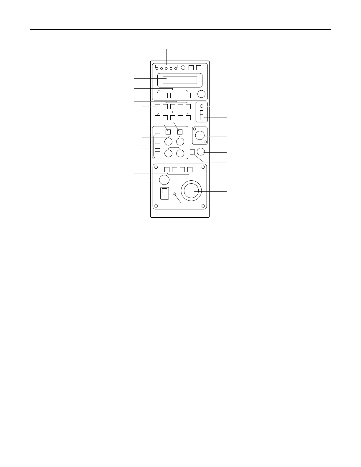
Parts and their function
1 TALLY lamps [1] to [5]
When tally signals are supplied to the (L) tally/INCOM
connectors [1] to [5] on the rear panel, the lamps with the
numbers corresponding to those connectors light up.
When tally signals are supplied to the tally connectors [1]
to [5] of the pan/tilt control panel, if this control panel is
connected to the ROP, the lamps with the numbers
corresponding to those connectors also light up.
2 LCD CONTRAST control
Use this to adjust the contrast of the LCD panel.
3 DATA SET button
Press DATA SET button and (6) CAM CONTROL
buttons [1] to [5] at the same time to synchronize the
setting data stored in the cameras selected with the
setting data stored in the ROP or vice versa.
Press only DATA SET button to synchronize the setting
data stored in all cameras connected to the ROP.
≥ In the case of the AW-E300, AW-E300A, AW-E600 or
AW-E800A cameras, the data stored in the ROP is
transferred to the cameras.
In the case of the AW-E350, AW-E650, AW-E655 or
AW-E750 cameras, the data stored in the cameras is
transferred to the ROP.
Data transfer takes two to three or so minutes.
≥ Press this button when the ROP is used for the first
time, or when the camera is replaced.
4 MENU button
Press this to turn the setting menu ON or OFF.
5 LCD panel
This displays the current settings.
6 CAM CONTROL buttons [1] to [5]
If the cameras are connected directly to the ROP, the
button lamps corresponding to numbers of the buttons
selected light, and the selected cameras can be
controlled by pressing buttons [1] to [5].
If the ROP is connected to the pan/tilt control panel for
use, the cameras installed to the pan/tilt head which is
connected to the pan/tilt control panel can be selected.
The buttons corresponding to the selected numbers light,
and selected cameras can be controlled.
When the ROP is connected to the pan/tilt control panel,
the camera selection function can be set to “From pan/tilt
control panel only”, “From ROP only” or “From both”,
depending on the setting selected by the pan/tilt control
panel. For further details, refer to the instruction manual
of the pan/tilt control panel.
5
6
7
8
9
:
;
=
>
@
<
?
A
C
D
E
F
G
H
J
I
3421
B
$ Front panel
Page 7

7
7 DTL button
Each time this is pressed, the detail is switched from ON
to OFF or vice versa. While the detail is ON, the button
lamp is lighted; while it is OFF, the button lamp is off.
The setting while the detail is ON is set using the menu.
8 SCENE FILE buttons [USER/1/2/3]
Use these to select the scene files of the camera.
9 GAIN buttons [0dB/L/M/H/AGC]
Use these to set the camera gain.
The gain-up function can be set to one of four levels
using the GAIN 0dB, L, M and H buttons.
The gain-up amount can be set for the L, M and H
buttons each using the respective menus.
When the AGC button is pressed, AGC is activated, and
the gain is adjusted automatically in accordance with the
light quantity.
The maximum AGC gain can be set using the menu.
: ABC button
Press this button to adjust the black balance
automatically.
While the black balance is being adjusted, the button
lamp flashes; when the adjustment is completed, it goes
off. It lights if the black balance could not be adjusted.
≥ The ABC button does not work when color bars have
been selected by the (<) BAR/CAM button (the button
lamp is lighted).
; AWC button
When this button is pressed while the A or B button
among the (=) ATW/A/B buttons is selected, the white
balance is automatically adjusted, and the adjustment is
registered in the camera’s AWC A or AWC B memory.
While the white balance is being adjusted, the AWC
button lamp flashes, and when it is adjusted properly, it
goes off. It lights if the white balance could not be
adjusted.
≥ The AWC button does not work when color bars have
been selected by the (<) BAR/CAM button (the button
lamp is lighted) or when the ATW button among the
(=) ATW/A/B buttons is selected (the ATW button
lamp is lighted).
≥ It may not be possible to adjust the white balance if the
screen does not show an image with a white object.
< BAR/CAM button
Use this to select the camera’s video output signals.
Each time it is pressed, the camera signals are switched
from color bar signals to video signals or vice versa.
While color bar signals are selected, the button lamp is
lighted; while video signals are selected, it is off.
= ATW/A/B buttons
Use these to select the white balance adjustment mode.
ATW: When the ATW button is pressed, the automatic
adjustment mode is established for the white
balance, and the ATW button lamp lights.
A: When the A button is pressed, the white balance
registered in the camera’s AWC A memory is
established, and the A button lamp lights.
When the (;) AWC button is pressed after
pressing the A button, the white balance is
automatically adjusted and registered in the
camera’s AWC A memory.
B: When the B button is pressed, the white balance
registered in the camera’s AWC B memory is
established, and the B button lamp lights.
When the (;) AWC button is pressed after
pressing the B button, the white balance is
automatically adjusted and registered in the
camera’s AWC B memory.
> R/B GAIN dials
These enable the white balance to be adjusted manually
after selecting the A or B button among the (=) ATW/A/B
buttons and the white balance has been automatically
adjusted by pressing the (;) AWC button.
When exercising control over the AW-E350, AW-E650,
AW-E655 or AW-E750, the change of setting value in the
dial’s setting can be switched from “large” to “small” or
vice versa by pressing the CONT dial.
? R/B PED dials
These enable the black balance to be adjusted manually
after the black balance has been automatically adjusted
by pressing the (:) ABC button.
When exercising control over the AW-E350, AW-E650,
AW-E655 or AW-E750, the change of setting value in the
dial’s setting can be switched from “large” to “small” or
vice versa by pressing the CONT dial.
@ OPTION SW [A to D] buttons
Refer to “Menu settings” for details on the items which
can be set in these OPTION SW buttons.
Parts and their function
Page 8

8
Parts and their function
A PED dial
This enables the total pedestal of the cameras to be set.
When exercising control over the AW-E350, AW-E650,
AW-E655 or AW-E750, the change of setting value in the
dial’s setting can be switched from “large” to “small” or
vice versa by pressing the CONT dial.
B IRIS [AUTO/MANU/LOCK] button
Use this to select the method for adjusting the lens iris of
the cameras selected by the CAM CONTROL buttons.
Each time it is pressed, the setting is switched in the
sequence of AUTO, MANU and LOCK.
AUTO: The cameras automatically adjust the lens iris in
accordance with the light quantity, and the button
lamp lights.
MANU: The lens iris is adjusted manually using the (I)
IRIS dial. At this setting, the button lamp is off.
LOCK: The lens iris is locked at the manually adjusted
setting. It cannot be adjusted even by turning the
(I) IRIS dial. When the (I) IRIS dial is turned,
the button lamp flashes to indicate that the lens
iris cannot be adjusted.
When the ROP is connected to the pan/tilt control panel,
the lens iris control can be set to “From pan/tilt control
panel only”, “From ROP only” or “From both”, depending
on the setting selected by the pan/tilt control panel. For
further details, refer to the instruction manual of the
pan/tilt control panel.
C CONT dial
Use this for menu setting operations.
D OPERATE lamp
When the (E) OPERATE switch is at ON, this lamp lights
up green; when it is at OFF, the lamp is off.
E OPERATE [OFF/ON] switch
Camera control is enabled by setting this switch to ON.
F INCOM jack
The INCOM (inter-communication) headset is connected
here.
G LEVEL control
Use this to adjust the volume of the headset’s receiver.
H CALL button
When this button is pressed, the buzzer of the connected
controller sounds, and the button lamp lights.
I IRIS dial
The lens iris can be adjusted by turning this dial while the
(B) IRIS [AUTO/MANU/LOCK] button is set to MANU.
The iris is opened by turning the dial clockwise and
stopped by turning it counterclockwise.
By pressing the (C) CONT dial, the response speed can
be switched from “fast” to “slow” or vice versa.
J FAST/SLOW lamp
When the response speed of the (I) IRIS dial is at “fast”,
this lamp lights up; when it is at “slow”, the lamp is off.
Note
When the ROP is connected to the pan/tilt control panel,
camera control is not possible unless the OPERATE
switch on the pan/tilt control panel is set to ON.
Page 9

9
K CONTROL OUT TO CONTROL PANEL
connector
When connecting the pan/tilt control panel for operation,
connect this connector to the CAMERA CONTROL IN
FROM ROP connector on the pan/tilt control panel using
the control panel’s connecting cable. The cameras are
then controlled through the pan/tilt control panel.
L TALLY/INCOM connector
Connect this to the TALLY/INCOM connector on the
video switcher or other units.
When the TALLY connector is set to the GND level, the
(1) TALLY lamp lights. Do not apply a voltage in excess
of 5V to this connector.
Use the accessory tally/INCOM connector (D-SUB 15-pin)
to connect the tally/INCOM signals to the system.
Connect a 4-wire INCOM system to the INCOM
connector.
When the ROP has been connected to the pan/tilt control
panel, the tally/INCOM functions of the ROP and the
pan/tilt control panel will be executed if the tally/INCOM
signals are connected to the ROP or the pan/tilt control
panel.
M
CONTROL OUT TO CAMERA connectors [1] to [5]
Connect these to the convertible cameras.
Use the connecting cables (optional accessory)
AW-CA50T8 or AW-CA50T9 + RS-422/RS-232C
converter to connect these connectors to the I/F
REMOTE connectors on the convertible cameras.
N DC 12V IN socket
Connect the AW-PS505 AC adaptor (optional accessory)
to this socket.
When the ROP is connected to the pan/tilt control panel
using the pan/tilt control panel connecting cable, power
will be supplied to the ROP from the pan/tilt control panel.
O Grounding terminal
Connect this terminal to ground.
KL
M
N
O
$ Rear panel
Pin No. Signal Name
1 TALLY1
9 TALLY2
2 TALLY3
10 TALLY4
3 TALLY5
11 TALLY GND
4 – – –
12 – – –
5 – – –
13 – – –
6 MIC +
14 MIC –
7 INCOM GND
15 SP –
8 SP +
87654321
?>=<;:9
Pin layout as seen from the
back panel of AW-CB400
Parts and their function
Page 10

10
Connections
$ When connecting a convertible camera directly
• First, turn off the power of all the equipment before proceeding with the connections.
• Use the AW-PS505 for the AC adaptor of the ROP.
Connect the DC 12V OUT socket on the AW-PS505 to the DC 12V IN socket on the ROP using the DC cable provided with
the AW-PS505.
• Use the AW-PS505 for the AC adaptor of the convertible camera.
Connect the DC 12V OUT socket on the AW-PS505 to the DC 12V IN socket on the convertible camera using AW-CA4T1.
• Connect the CONTROL OUT TO CAMERA connectors [1] to [5] on the ROP with the I/F REMOTE connectors on the
convertible cameras through the connecting cables (optional accessory) AW-CA50T8 or AW-CA50T9 + RS-422/RS-232C
converter.
The distance between the ROP and the AW-CA50T8 or AW-CA50T9 + RS-422/RS-232C converter can be extended up to
a maximum of about 1000 meters using a 10Base-T (equivalent to UTP category 5) straight cable.
$ When connecting the ROP in a system that includes pan/tilt heads, pan/tilt control
panel and cable compensation unit
• First, turn off the power of all the equipment before proceeding with the connections.
• Connect the CONTROL OUT TO CONTROL PANEL connector on the ROP with the CAMERA CONTROL IN FROM ROP
connector on the pan/tilt control panel using the pan/tilt control panel connecting cable provided with the ROP.
• Power will be supplied to the ROP from the pan/tilt control panel.
• For details on how to connect the pan/tilt heads, pan/tilt control panel and cable compensation unit, refer to the instruction
manual provided with these units.
Page 11

11
$ When connecting a camera directly
Zoom lens
Convertible
camera
AW-CA4T1
Iris control
Cable provided
with AC adaptor
AC adaptor
AW-PS505
AW-CA50T8
or
AW-CA50T9 +
RS-422/RS-232C converter
AC adaptor
AW-PS505
Monitor
Control signal
Video signal
10Base-T straight cable
Remote Operation Panel
AW-CB400
Example of system configuration
Page 12

12
Example of system configuration
$ When connecting the ROP in a system that includes pan/tilt heads, pan/tilt control
panel and cable compensation unit
Convertible camera
Pan/Tilt Head
AW-PH400
Composite video or
component video
signals
To switcher,
monitor
G/L
AC adaptor
AW-PS505
Cable provided
with AW-CB400
AW-CA50T8
or
AW-CA50T9 +
RS-422/RS-232C
converter
Monitor
Headset
Headset
Monitor
Monitor switching
Genlock signals
MONITOR2
MONITOR1
Remote
Operation Panel
AW-CB400
Pan/tilt Control Panel
AW-RP400
Cable Compensation
Unit
AW-RC400
When a pan/tilt head system and cameras have been connected to the CONTROL OUT connectors on
the pan/tilt control panel and the CONTROL OUT connectors with the corresponding numbers on the
ROP, the camera control exercised by the pan/tilt head system connected to the CONTROL OUT
connectors on the pan/tilt control panel takes priority, and the camera connected directly to the ROP
cannot be controlled.
❈ For details on how to connect the pan/tilt heads and pan/tilt control panel, refer to the instruction manual provided with
the pan/tilt control panel.
Cable provided
with AC adaptor
AC adaptor
AW-PS301
Page 13

13
Example of system configuration
$
When the distance between the ROP and the pan/tilt control panel is more than 10 meters
The distance between the ROP and the pan/tilt control panel can be extended up to a maximum of about 1000 meters on the
following condition using the provided cable (refer following specifications) and/or equivalent cables. (Prepare the cables of
required length.)
• Up to 50 meters: Use the recommended AC adaptor for the power supply of the pan/tilt control panel.
• More than 50 meters: Supply DC 12V to the ROP and the pan/tilt control panel from the recommended AC adaptor.
In this case, it is not necessary to connect +12V IN.
Specifications for provided cable
Ferrite core
Ferrite core
Use the twist pair cables.
Connector used
Japan Aviation Electronics Industry, Ltd.
Connector: D02-29PF-N-F0
Contact: D02-22-26P-PKG100
(For AWG 26 to 28)
Case: DA-C4-J10
Connector used
Japan Aviation Electronics Industry, Ltd.
Connector: D02-29SF-N-F0
Contact: D02-22-26S-PKG100
(For AWG 26 to 28)
Case: DA-C4-J10
Shield Shield
Page 14

14
$ Turning on the power
Turn on the power.
First set the power switch on the AC adaptor used for the ROP and the AC power switches on the cameras to ON, and set
the OPERATE switch on the ROP to ON.
$ Adjusting the cable compensation of each camera
For details on providing cable compensation for the cameras, refer to the instruction manual provided with the cable
compensation unit.
$ Genlock adjustments for each camera
If the cameras are to be used in the genlock mode, phase adjustment is required in order to adjust the phases between the
cameras and other units. Genlock adjustment is not needed if genlock is not going to be used.
Horizontal phase adjustment
1 Select the first camera to be adjusted by pressing the CAM CONTROL button.
2 Press the MENU button, and display the camera setting menu on the LCD panel.
3 Turn the CONT dial, and display the G/L SETTING menu.
4 Push the CONT dial straight down, and display H PHASE on the bottom line of the LCD.
5 Observe the waveforms of the genlock signal (black burst signal or video signal (VBS)) and video signal output on an
oscilloscope, and adjust the CONT dial in such a way that the horizontal phase is adjusted as shown in the figure below.
6 Select the next camera by pressing the CAM CONTROL button, and adjust the horizontal phase of the next camera.
Repeat this for all the connected cameras.
Adjust the horizontal phase here.
External sync (genlock)
signal input (black
burst signal)
Video signal output
Operating procedure
Page 15

15
Operating procedure
Sub carrier phase adjustment
1 Select the first camera to be adjusted by pressing the CAM CONTROL button.
2 Press the MENU button to display the menu on the LCD panel.
3 Turn the CONT dial to display the G/L SETTING menu.
4 Push the CONT dial straight down twice to display SC COARSE on the bottom line of the LCD. The sub carrier phase can
now be adjusted coarsely by turning the CONT dial.
When the CONT dial is pushed three times, SC FINE appears, and the sub carrier phase can now be adjusted finely by
turning the CONT dial.
5 Keep adjusting the SC COARSE and SC FINE phase so that the sub carrier (color) phase of the video signal output is
aligned with the colors of the program output (split color bar output) of the video switcher or other unit that serves as the
reference.
The color phase can be adjusted more accurately if a vectorscope is used.
6 Select the next camera by pressing the CAM CONTROL button, and adjust the sub carrier phase of the next camera.
Repeat this for all the connected cameras.
$ Video adjustment of cameras
This adjustment is performed when the pedestal of a multiple number of cameras is to be brought into alignment.
1 Select the first camera to be adjusted by pressing the CAM CONTROL button.
2 Set the lens iris to manual, and stop it down.
3 Use an oscilloscope or waveform monitor to adjust the pedestal level to correspond to the reference level using the total
pedestal dial.
4 Select the next camera by pressing the CAM CONTROL button, and adjust the pedestal of the next camera. Repeat this
for all the connected cameras.
White
Yellow
Cyan
Green
Magenta
Red
Blue
Black
Color bars of camera
Split line
Color bars of special
effects unit
Adjust the pedestal level
to the reference level.
Page 16

16
$ Operation method
The GAIN information appears first when the OPERATE
switch is set to ON.
When the MENU button is pressed, the display changes in
the sequence shown below, after which the display returns
to the gain setting screen.
Z Gain setting
;
Z Pedestal setting
;
Z
DTL setting (when SCENE FILE is set to the USER mode)
Z DTL setting (when 1, 2 or 3 is set for SCENE FILE)
;
Z Camera settings
;
Z Remote operation panel settings
;
Z LCD off
(LCD off)
(ROP settings)
(Camera setting items)
DETAIL
HIGH
DETAIL H DETAIL
15
PEDESTAL T: 0
R: 0 B: 0
GAIN 0dB
R: 0 B: 0
1 Gain setting
The gain of the camera selected by the CAM CONTROL
button is set on this display.
The analog gain-up value appears on the right of the top
line, and the gain information for the lighted GAIN button
is displayed.
The R gain and B gain settings are shown on the bottom
line.
When the R or B GAIN dial is turned, the R or B gain is
incremented or decremented. The value which can be set
differs depending on the camera concerned.
The values corresponding to white balance A and B can
be stored in the memory. When the automatic adjustment
mode (ATW among the ATW, A and B buttons) has been
selected for the white balance, “– – –” appears on the
display, and the gain cannot be set.
2 Pedestal setting
The pedestal of the camera selected by the CAM
CONTROL button is set on this display.
The total pedestal setting is shown on the top line, and
the R pedestal and B pedestal settings on the bottom
line.
When the R or B PED dial is turned, the R or B pedestal
is incremented or decremented. The value which can be
set differs depending on the camera concerned.
3 DTL setting
The horizontal detail and vertical detail of the camera
selected by the CAM CONTROL button is set on these
displays.
When USER is selected for SCENE FILE, any value from
0 to 63 can be set as the H DETAIL and V DETAIL level.
Press the CONT switch to switch between H and V.
When 1, 2 or 3 is set for SCENE FILE, use the CONT dial
to switch between HIGH and LOW.
4 Camera settings
The detailed settings of the camera selected by the CAM
CONTROL button are set on these displays.
Turn the CONT dial to select the setting item, and press it
to display the settings on the bottom line. If the CONT
dial is turned while the setting is displayed, the setting
can be changed. Upon completion of the setting, press
the CONT dial to clear the bottom line display, and
another setting item can now be selected.
5 Remote operation panel settings
The controller settings are set on these displays.
Operation is the same as that for “4 Camera settings”.
6 Exiting the setting menu
Press the MENU button to exit the setting menu.
Menu settings
Page 17

17
Menu settings
$ Items which can be selected on the camera setting display
PICTURE LEVEL –50 to +50 0
LIGHT PEAK/AVG P50 to A50 0
LIGHT AREA ALL, CENTER, TOP CUT
TOP CUT,
BTM CUT, L/R CUT
SHUTTER 1/100, 1/250, 1/500, OFF
1/1000, 1/2000,
1/4000, 1/10000,
SYN-SCAN, ELC
SYNCHRO SCAN
DIGITAL GAIN 0, 6, 12, 18, 24, 30dB 0dB
AGC MAX LEVEL OFF, 6, 12, 18, 24, 30,
N/Eye L, N/Eye H
CHARGE TIME 2S, 1S, 1/2S, 1/4S, 1/8S, 1/15S, OFF
1/30S, OFF, AUTO,
CHROMA LEVEL –3 to +3 0
ATW SPEED SLOW2, SLOW1, MIDDLE
MIDDLE,
FAST1, FAST2
NEGA/POSI POSI, NEGA POSI
H PHASE –206 to +49 0
SC COARSE 0°, 90°, 180°, 270° 0°
SC FINE –511 to +511 0
COLOR BAR SET 0.0%, 7.5% 7.5%
DETAIL BAND 1 to 5 2
NOISE SUPPRESS 0 to 10 3
LEVEL DEPENDENT 0% to 25% 0%
DARK DETAIL 0 to 5 0
CHROMA DETAIL 0 to 15 0
DTL FLESH TONE LOW, MID, HIGH MID
CORNER DETAIL OFF, ON OFF
PRECISION DTL OFF, ON OFF
MATRIX B_Mg GAIN –127 to +127 0
MATRIX B_Mg PHAS –127 to +127 0
MATRIX Mg GAIN –127 to +127 0
MATRIX Mg PHASE –127 to +127 0
MATRIX Mg_R GAIN –127 to +127 0
MATRIX Mg_R PHAS –127 to +127 0
MATRIX R GAIN –127 to +127 0
MATRIX R PHASE –127 to +127 0
MATRIX R_Yl GAIN –127 to +127 0
MATRIX R_Yl PHAS –127 to +127 0
MATRIX Yl GAIN –127 to +127 0
MATRIX Yl PHASE –127 to +127 0
MATRIX Yl_G GAIN –127 to +127 0
MATRIX Yl_G PHAS –127 to +127 0
Item Setting Initial value
Page 18

18
MATRIX G GAIN –127 to +127 0
MATRIX G PHASE –127 to +127 0
MATRIX G_Cy GAIN –127 to +127 0
MATRIX G_Cy PHAS –127 to +127 0
MATRIX Cy GAIN –127 to +127 0
MATRIX Cy PHASE –127 to +127 0
MATRIX Cy_B GAIN –127 to +127 0
MATRIX Cy_B PHAS –127 to +127 0
MATRIX B GAIN –127 to +127 0
MATRIX B PHASE –127 to +127 0
GAMMA 0.35 to 0.55 0.45
KNEE POINT DYNAMIC, 88%
88% to 98%
WHITE CLIP 95% to 110% 110%
FLARE R 0 to 100 0
FLARE G 0 to 100 0
FLARE B 0 to 100 0
BLACK STRETCH OFF, ON OFF
CLEAN DNR OFF, LOW, HIGH OFF
3D-DNR OFF, LOW, MID, HIGH OFF
2D-LPF OFF, LOW, HIGH OFF
FIELD/FRAME FIELD, FRAME FIELD/FRAME
COMPONENT R/G/B , Y/Pb/Pr, Y/C Y/Pb/Pr
DIGITAL EXTENDER OFF, ON OFF
ZEBRA INDICATOR OFF, ON OFF
ZEBRA LEVEL 70% to 110%
SAFETY ZONE 1, 2, 3, 4, 5, OFF 4
EVF OUTPUT Y, CVBS CVBS
Item Setting Initial value
❈ Concerning the camera setting items
The functions that can be controlled vary depending on the camera connected.
If a camera does not support a particular function, its setting will not take effect even if that function appears on the menu.
For details on the functions featured by a specific camera, refer to the camera’s instruction manual.
Menu settings
Page 19

19
Menu settings
$ Items which can be selected on the remote operation panel setting display
OPTION A - D settings (NOT USE, TELE, WIDE, NEAR, FAR, AF, IR THROUGH, 1/16ND, 1/64ND)
The following functions can be allocated to the OPTION SW [A] to [D] buttons.
NOT USE: The button’s function is canceled.
TELE, WIDE, NEAR, FAR:
When a convertible camera or AW-E655 camera, into which has been inserted an optional card with the lens
I/F card function, has been directly connected to the ROP, it is possible to control the zooming and focusing
of the motorized lens.
With the TELE setting, the lens is zoomed toward the “TELE” end for as long as the option button is held
down.
With the WIDE setting, the lens is zoomed toward the “WIDE” end for as long as the option button is held
down.
With the NEAR setting, the lens is focused toward the “NEAR” end for as long as the option button is held
down.
With the FAR setting, the lens is focused toward the “FAR” end for as long as the option button is held down.
AF: When a lens provided with the auto focus function is used, the ON and OFF settings of the auto focus
function are controlled.
Each time the button is pressed, the setting is switched from ON to OFF or vice versa.
When the auto focus function is set to ON, the lamp of the button to which this function has been allocated
lights; when it is set to OFF, the lamp is off.
IR THROUGH: The motorized filter of the AW-E655 is set to IR THROUGH. When the button is pressed again, it is set to
NORMAL.
The lamp of the button lights when the filter is set to IR THROUGH; it is off when another filter is selected.
1/16 ND: The motorized filter of the AW-E655 is set to 1/16ND. When the button is pressed again, it is set to
NORMAL.
The lamp of the button lights when the filter is set to 1/16ND; it is off when another filter is selected.
1/64 ND: The motorized filter of the AW-E655 is set to 1/64ND. When the button is pressed again, it is set to
NORMAL.
The lamp of the button lights when the filter is set to 1/64ND; it is off when another filter is selected.
BUZZER setting (OFF/ON)
This is used to set for the buzzer inside the remote operation panel to ON or OFF. The buzzer does not sound at the OFF
setting.
The buzzer sounds when the CALL button is pressed.
Item Setting Initial value
OPTION A
OPTION B NOT USE, TELE, WIDE, FAR, NEAR, AF
NOT USE
OPTION C IR THROUGH, 1/16ND, 1/64ND
OPTION D
BUZZER OFF, ON ON
Page 20

20
1 Remove the rubber caps on the side panels.
2 Use the accessory mounting screws (M4!8 mm) to attach the rack-mounting adaptors. Remove the rubber caps.
1 Remove the rubber caps on the side panels of the AW-CB400.
2 Attach the accessory join-up screws (stepped screws) to the two places on the side of the ROP which is to be joined to
the AW-RP400.
3 Adhere the joining stickers onto the side panels of the AW-RP400 concentrically with the join-up screws.
4 Align the holes of the AW-CB400 with the join-up screws, shift in the direction shown by the arrow, and fit the two
units together to make a single integrated unit.
5 Attach the join-up fixture to bottom panels of the AW-RP400 and AW-CB400.
6 Attach the rack-mounting adaptors using the mounting screws (M4!8 mm) provided.
Rack-mounting adaptors
Join-up screws (stepped screws)
❈ When the AW-RP400 is to be joined on the left of the AW-CB400.
Accessory mounting
screws (M4!8 mm)
4 pcs
Mounting screws (accessory)
M4!8 mm ..... 4 pcs
Join-up fixture
Remove the rubber caps.
Rubber cap
Join-up screws (stepped screws)
How to mount the ROP in a rack
Joining the ROP to the AW-RP400 and mounting the joined-up units in a rack
Joining sticker
Joining sticker
<NOTE> ≥ The AW-CB400 is 100 mm wide. If it is to be installed in a full-size rack (which accommodates units totaling
420 mm in width), provide panels or other parts to supplement the AW-CB400’s width so that it will fill the
rack width-wise.
≥ If the AW-CB400 is joined to the AW-RP400, the resulting width will be equivalent to that of the full width of
the rack (which accommodates units totaling 420 mm in width).
100mm
AW-CB400
AW-RP400
AW-CB400
Page 21

5 Secure the connector panel to the bottom panel using the
screws.
Screws (!3)
Attach the
connector
panel.
21
How to change the position of the connector panel
The position of the connector panel can be changed from the rear panel to the bottom panel.
1 Remove the three screws of the bottom and side panels
to remove the blank panel.
2 Remove the three screws of the rear and side panels to
remove the connector panel.
3 Secure the blank panel to the rear panel using the
screws.
4 Remove the two rubber feet of the blank panel.
Screws (!3)
Remove the
blank panel.
Screws (!3)
Connector panel
Screws (!5)
Attach the blank panel.
Rubber feet
(Rear view)
(Rear view)
Page 22

22
Input connectors
DC 12V IN: XLR, 4 pins
GND: GND terminal
Output connectors
CONTROL OUT
TO CONTROL PANEL: D-SUB 29-pin
CONTROL OUT
TO CAMERA 1 to 5: RJ45, camera control RS-422 level
10Base-T straight cable (UTP category 5), max. 1000 meters
Input/output connectors
INCOM (top panel): XLR, 4 pins
TALLY/INCOM: D-SUB 15-pin
TALLY: Contact input (do not apply a voltage in excess of 5V)
INCOM: 4-wire system
Switch functions: DATA SET, menu, camera control selection, DTL, scene file selection, gain selection,
BAR/CAM switching, white balance selection, AWC, ABC, call, lens iris
AUTO/MANU/LOCK switching, option switches (1 to 4)
Adjustment functions: LCD contrast, INCOM level, lens iris, menu settings, R-GAIN, B-GAIN, pedestal, R-PED,
B-PED
Ambient operating temperature: 14°F to 113°F (–10°C to +45°C)
Storage temperature: –4°F to 140°F (–20°C to +60°C)
Ambient operating humidity: 30% to 90% (no condensation)
Dimensions (W!H!D): 3-15/16”!3-3/8”!10-1/2” (100!85!266 mm)
Weight: 3.1 lbs (1.4 kg)
Finish: Color resembling Munsell 3.5 paint
Weight and Dimensions indicated above are approximate.
Specifications are subject to change without notice.
Supply voltage: DC 12.0 V
Power consumption: 3.8 W
Specifications
1 indicates safety information.
Page 23

23
Page 24

PANASONIC BROADCAST & TELEVISION SYSTEMS COMPANY
UNIT COMPANY OF MATSUSHITA ELECTRIC CORPORATION OF AMERICA
Executive Office:
One Panasonic Way 4E-7, Secaucus, NJ 07094 (201) 348-7000
EASTERN ZONE:
One Panasonic Way 4E-7, Secaucus, NJ 07094 (201) 348-7621
Southeast Region:
1225 Northbrook Parkway, Ste 1-160, Suwanee, GA 30024 (770) 338-6835
Central Region:
1707 N Randall Road E1-C-1, Elgin, IL 60123 (847) 468-5200
WESTERN ZONE:
3330 Cahuenga Blvd W., Los Angeles, CA 90068 (323) 436-3500
Government Marketing Department:
52 West Gude Drive, Rockville, MD 20850 (301) 738-3840
Broadcast PARTS INFORMATION & ORDERING:
9:00 a.m. – 5:00 p.m. (EST) (800) 334-4881/24 Hr. Fax (800) 334-4880
Emergency after hour parts orders (800) 334-4881
TECHNICAL SUPPORT:
Emergency 24 Hour Service (800) 222-0741
Panasonic Canada Inc.
5770 Ambler Drive, Mississauga, Ontario L4W 2T3 (905) 624-5010
Panasonic de Mexico S.A. de C.V.
Av angel Urraza Num. 1209 Col. de Valle 03100 Mexico, D.F. (52) 1 951 2127
Panasonic Sales Company
Division of Matsushita Electric of Puerto Rico Inc.
San Gabriel Industrial Park, 65th Infantry Ave., Km. 9.5, Carolina, Puerto Rico 00630 (787) 750-4300
 Loading...