

Page 1

日
本
語
ENGLISHDEUTSCHFRANÇAISITALIANOESPAÑOL
中
文
Digital Video Interface Board
Operating Instructions
VQT0C33
Before operating this product, please read the instructions carefully and
save this manual for future use.
Model No. AJ-
G
Page 2
2(E)
Precautions
• Do not touch this product with wet hands.
• Do not drop this product or subject it to other strong shock.
• Do not attempt to modify this product. Doing so may cause it to malfunction.
If the “SDTI/1394” input cannot be selected by the VIDEO INPUT SELECT
button even though the board has been installed correctly, the version of the
software and hardware in the AJ-SD930 and AJ-SD955 digital VTR may need to
be updated. Consult your dealer for details on updating the software and
hardware versions.
The AJ-YAD955G is a digital video interface board designed for use
exclusively with the AJ-SD930 and AJ-SD955 series of digital VTRs. It cannot
be used with the AJ-D455, AJ-D450 or AJ-D440.
Consult your dealer regarding installation in the AJ-SD930 and AJ-SD955
series.
CAUTION:
TO REDUCE THE RISK OF FIRE OR SHOCK HAZARD, REFER
MOUNTING OF THE INTERFACE BOARD TO AUTHORIZED
SERVICE PERSONNEL.
CAUTION:
TO REDUCE THE RISK OF FIRE OR SHOCK HAZARD AND
ANNOYING INTERFERENCE, USE THE RECOMMENDED
ACCESSORIES ONLY.
1 indicates safety information.
Page 3

ENGLISH
3(E)
Features
The AJ-YAD955G is a digital video interface board which is designed to be used
exclusively with the AJ-SD930 and AJ-SD955 series of digital VTRs.
When it is installed in the AJ-SD930 or AJ-SD955 series, video and audio signals as well
as time code signals can be transferred digitally to a PC (*) or digital VTR in compliance
with the IEEE 1394 standard.
* Depending on the application (editing) software and hardware (IEEE1394 interface) being
used, transmission of video signals and audio signals for all channels may not be possible.
Models supported
Digital VTRs: AJ-SD930 and AJ-SD955 series
Accessories
• Connector board (t1)
• Connecting cable (t1)
Contents
Precautions . . . . . . . . . . . . . . . . . . . . . . . 2
Features . . . . . . . . . . . . . . . . . . . . . . . . . . 3
Models supported . . . . . . . . . . . . . . . . . 3
Accessories. . . . . . . . . . . . . . . . . . . . . . . 3
Installing the board in the
AJ-SD930 and AJ-SD955 series. . . . . 4
AJ-SD930 and AJ-SD955 series
settings. . . . . . . . . . . . . . . . . . . . . . . . . . . 6
Precautions for use. . . . . . . . . . . . . . . . 7
Setup menus . . . . . . . . . . . . . . . . . . . . . . 8
Warning messages . . . . . . . . . . . . . . . 10
Specifications. . . . . . . . . . . . . . . . . . . . 11
Page 4
4(E)
Coin screws
SW-1
ON
1
234
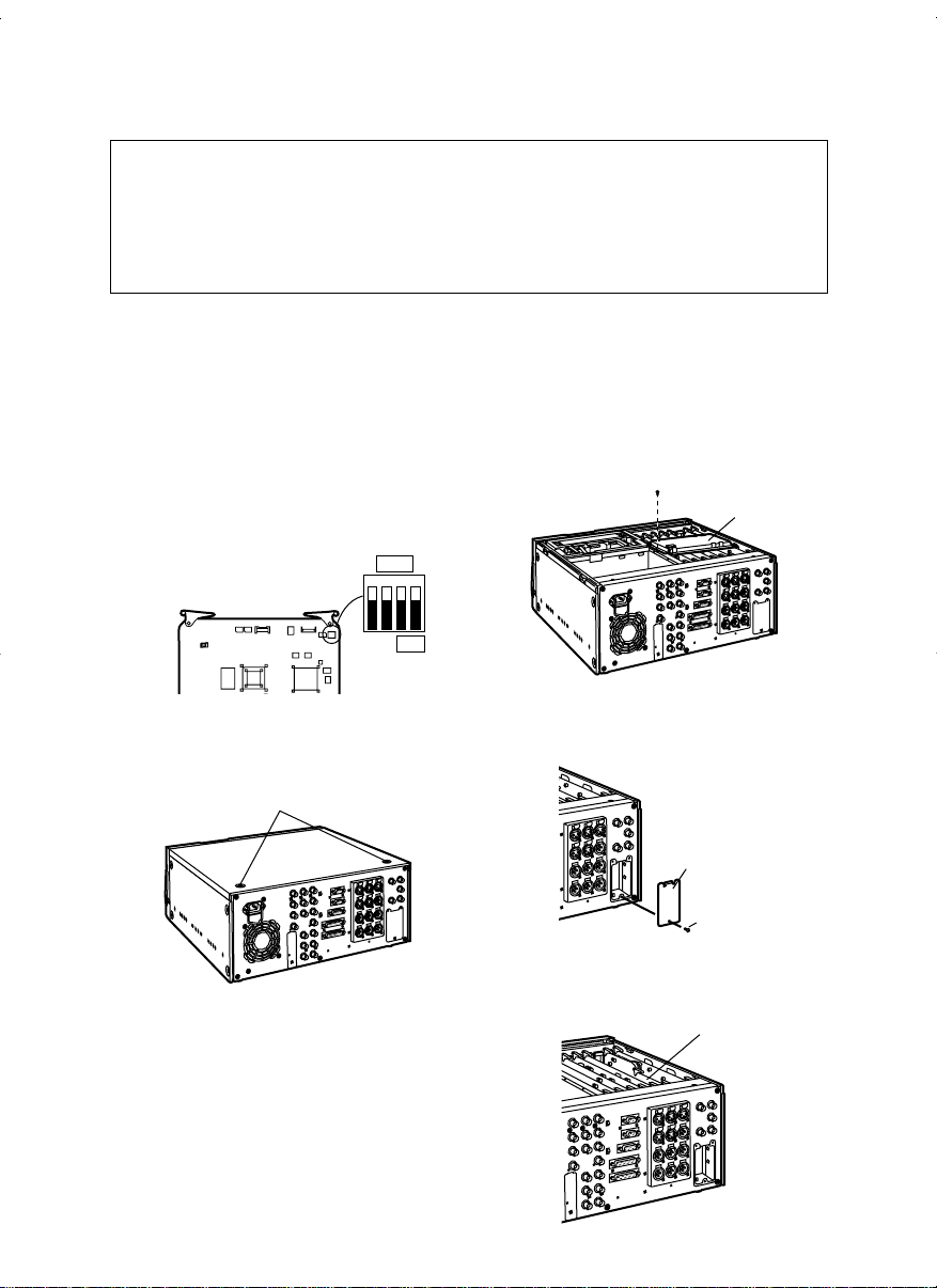
The AJ-YAD955G must be installed in the AJ-SD930 and AJ-SD955 in order for it to be
used. Follow the procedure below for installation.
2
Check that the DIP switches on the
AJ-YAD955G are set to the positions
shown in the figure below.
Installing the board in the AJ-SD930 and AJ-SD955 series
3
Remove the 2 coin screws and top
panel from the unit.
1
Disconnect the power cord from the
unit.
Screw
Board clamp
4
Remove the screw and the board
clamp.
Screw
Blank panel
5
Remove the screw and remove the
blank panel from the rear panel.
CAUTION:
These servicing instructions are for use by qualified service
personnel only. To reduce the risk of fire or electric shock do not
perform any servicing other than that contained in the operating
instructions unless you are qualified to do so.
SDI board
6
Remove the SDI board from the slot
marked “F3” of the rear panel side.
Page 5

ENGLISH
5(E)
Installing the board in the AJ-SD930 and AJ-SD955 series
8
Reinsert the SDI board in the F3 slot
on the rear panel side, then insert the
interface board into the front panel
side of the F3 slot .
F3
Screw
Coin screws
Board
clamp
9
Attach the board clamp with the
screw and secure the top panel to the
unit with the 2 coin screws.
Screw
Connector
board
7
Attach the accessory connector board
to the rear panel.
Pass the wiring through the rear panel,
attach the top side of the connector
board and secure the lower side of the
board in place with the screw, as shown
in the diagram below.
Ensure that wiring and connections are
as shown in the respective diagrams
below.
Clampers
View from rear
Connections
Diagram
Wiring Diagram
Clamper
Connector
Page 6

6(E)
<Notes>
• It is not possible to select SDTI/1394 for
AUDIO unless SDTI/1394 has been
selected for VIDEO.
• The recording formats for the input data
are determined as shown in the table
below.
AJ-SD930 and AJ-SD955 series settings
1
Check that “ON” has been selected
as the setting for setup menu item
No.220 “AV/C CMD SEL.”
3
When inputting signals from the
digital video interface, press the
INPUT SELECT button on the front
panel, and set the front display tube
VIDEO input selection to the
“SDTI/1394” position. Similarly, set
the AUDIO input selection to the
“SDTI/1394” position.
2
Check that “AUTO” has been
selected as the setting for both setup
menu items No.882 “DIF IN CH” and
No.883 “DIF OUT CH.”
*2 No recording is possible when “625”
has been selected as the setting for
setup menu item No.070 “TV SYSTEM”
of the AJ-SD955 or when the AJ-SD930
designed for the 625/50 system is used.
• The formats for the output data are
determined by the setting selected for
setup menu item No.881 “DIF TYPE”
and the playback tape (mode).
Setup menu item
NO.012 “SYS
FORMAT” setting
50M
25M
Input data
DVCPRO50
DVCPRO
DV
DVCPRO50
DVCPRO
DV
Recording
format data
DVCPRO50
No recording possible
No recording possible
No recording possible
DVCPRO
DVCPRO
(With the 525/60 TV
system)*1
or
No recording
(With the 625/50 TV
system)*2
*1 When the 32 kHz/4CH format applies to
the audio signals in the input data,
CH1/CH2 and CH3/CH4 can be
selected using setup menu item No.889
“DIF AUD IN.”
Mode
For DVCPRO50
tape playback
For DVCPRO
tape playback
For DV/DVCAM
tape playback
For eject
and E-E
Setup menu
item No.012
“SYS
FORMAT”
setting
"""
"""
"""
"""
"""
"""
"""
50M
25M
Setup menu
item No.881
“DIF TYPE”
setting
"""
AUTO
DVCPRO
DV
AUTO
DVCPRO
DV
"""
AUTO
DVCPRO
DV
Output
data format
DVCPRO50
DVCPRO
DVCPRO
DV
DV
DVCPRO
DV
DVCPRO50
DVCPRO
DVCPRO
DV
With the 525/60 TV system
Mode
For DVCPRO50
tape playback
For DVCPRO
tape playback
For DV/DVCAM
tape playback
For eject
and E-E
Setup menu
item No.012
“SYS
FORMAT”
setting
"""
____
"""
50M
25M
Output
data format
DVCPRO50
DVCPRO
DV
DVCPRO50
DVCPRO
With the 625/50 TV system
Page 7

ENGLISH
7(E)
Precautions for use
• Ensure that the connections with other devices are made on a 1:1 basis.
• When selecting the digital video interface as the input, “AUTO” must be selected
without fail as the setting for setup menu item No.304 “SERVO REF.”
• When warning E-92 (1394 INITIAL ERROR) appears, disconnect the connecting
cables and re-connect them or turn off the VTR's power and turn it back on.
• The AV signals may be disrupted by turning the power of the connected devices ON
and OFF or by disconnecting and re-connecting the I/F cables.
• It may take several seconds for the system to operate stably when the input signals are
switched or operation is transferred from one mode to another. Perform recording
operation after the system operation has stabilized.
• The following points should be borne in mind when it comes to recording with the digital
video interface input selected or outputting the signals by the digital video interface.
• The AUDIO LEVEL controls on the front panel will not work.
• The settings in the 800 order of setup menu items relating to the vertical blanking
period will be ignored.
• When playback signals other than regulark1 (normal speed) playback signals have
been input, no guarantees are made for the video and sound recorded or for the video
and sound of the EE system.
• The CUE signal cannot be transferred by the digital video interface. Neither is it
possible for the audio signals which have been multiplexed on the input data to be
recorded on the CUE track.
• The following points should be borne in mind when the video input selection has been
set as the digital video interface.
• SDI signals and analog video output signals in the E-E mode will become irregular.
These signals should not be used for recording purposes. (The teletext signals or
other signals which are multiplexed on the video output signals will also become
irregular.)
• When “SDI” has been set as the audio input selection, the reception of the SDI
embedded audio signals will be adversely affected by noise and other problems (i.e.
the signals will become irregular).
• During SLOW or STILL playback, video and audio signals which have not been
processed as the output signals of the digital video interface will be output. When
these video and audio signals are monitored on another device, they may be at
variance from the video and audio signals which are played back by this unit.
Page 8

8(E)
880 DIF
SPEED
0000
0001
0002
S100
S200
S400
For setting the transfer rate of the digital video interface output.
0: 100Mbps
1: 200Mbps
2: 400Mbps
For setting the format used for output.
0: The format is forcibly set to DVCPRO for output.
1: The format is forcibly set to DV for output.
2: The same format as that of the playback tape is set.
<Note>
This menu item setting is ignored when “50M” has been selected as
the setup menu item No.012 “SYS FORMAT” setting.
881 DIF
TYPE
(*1)
0000
0001
0002
DVCPRO
DV
AUTO
882 DIF
IN
CH
0000
|
0063
0064
0
|
63
AUTO
For setting the input channels.
0-63: These are fixed at designated values.
64: This is not fixed at a designated value.
When the power is turned on, the input channel is initialized to
63.
883
DIF
OUT
CH
0000
|
0063
0064
0
|
63
AUTO
For setting the output channels.
0-63: These are fixed at designated values.
64: This is not fixed at a designated value.
When the power is turned on, the output channel is initialized to
63.
886 DIF
CONFIG
0000
0001
|
0255
DFLT
1
|
255
Expansion menu
Normally, the “DFLT” setting is used for this item.
889 DIF
AUD
IN
(*1)
0000
0001
CH1&2
CH3&4
For selecting the channels whose audio signals will be recorded on
the tape when a 4-channel audio mode DV format data is to be
received and recorded onto a DVCPRO tape.
0: CH1 and CH2 of the DV format data received are selected.
1: CH3 and CH4 of the DV format data received are selected.
Item
Setting
No.
Superimposed
display
No.
Superimposed
display
Description of settings
220 AV/C
CMD
SEL
0000
0001
OFFONFor selecting whether to use the digital video interface AV/C
command when the REMOTE/LOCAL switch is at the REMOTE
position.
0: The AV/C command is not used.
1: The AV/C command is used.
The underlining indicates the factory setting.
Setup menus
The following setup menu items can be used when the AJ-YAD955G has been installed
in the AJ-SD930 and AJ-SD955.
*1: This item does not appear with the 625/50 TV system.
Page 9

ENGLISH
9(E)
Setup menus
The underlining indicates the factory setting.
Item
Setting
No.
Superimposed
display
No.
Superimposed
display
Description of settings
891 DIF DV
AUDIO
0000
0001
0002
THRU
LOCK
LOCK48
For setting the forced audio mode conversion when playing back a
DV tape and outputting the signals in the DV format.
0: Normal (the signals simply pass through normally).
1: Forcibly converted to the LOCK mode (the frequency is not
converted).
2: Forcibly converted to the 48 kHz/2CH/LOCK mode.
893 JUST
IN REC
0000
0001
0002
OFF
MODE_A
MODE_I
For setting the JUST IN REC function. (This function is set to
enhance the accuracy of the recording with frame-to-frame
continuity.)
0: Disabled (this setting is the one normally used).
1: Enabled (assemble mode)
2: Enabled (insert mode)
<Notes>
The JUST IN REC function is subject to the following restrictions.
• This function does not operate when using personal computer
editing software.
• The length of the video data to be recorded must be 1 or more
seconds.
890 DIF
AUD
OUT
0000
0001
CH1&2
CH3&4
For selecting the channels of the audio signals when a 4-channel
audio mode DV tape is to be played back and the signals are to be
output in the DVCPRO format.
0: CH1 and CH2 of the DV tape are selected.
1: CH3 and CH4 of the DV tape are selected.
Page 10

10(E)
Warning messages
By installing the AJ-YAD955G in the AJ-SD930 and AJ-SD955, the following warning
messages are additionally provided.
These messages will appear on the mode display when “T&S&M” has been selected as
the setup menu item No.003 (DISPLAY SEL) setting.
This appears when the signals which have been input from the digital
video interface are not in the DVCPRO or DV format.
Display on monitor
screen (counter display)
Description
Opera-
tion
*1
*1
*2
*3
This appears when the signals which have been input from the digital
video interface are notk1 speed transfer signals in the DVCPRO or DV
(25 Mbps) format.
This appears when the audio signals which have been input from the
digital video interface are irregular signals.
This appears when the time code information which has been input from
the digital video interface is irregular.
*1This appears when the signals which have been input from the digital
video interface are not k1 speed transfer signals in the DVCPRO50 (50
Mbps) format
*1This appears when the compressed video signals which have been
input from the digital video interface are irregular signals.
*4This appears when the connection status of the digital video interface is
irregular.
UNKNOWN SIG
(E-04)
NOT 1k25M SIG
(E-11)
NOT 1k50M SIG
(E-12)
INVALID VIDEO SIG
(E-16)
INVALID AUDIO SIG
(E-17)
INVALID TC SIG
(E-18)
1394 INITIAL ERROR
(E-92)
*1 When this warning has appeared during a recording operation, the video signals are recorded as black
screens and the audio signals are muted.
*2 When this warning has appeared during a recording operation, the audio signals are muted.
*3 When this warning has appeared during a recording operation, the time code generated internally is recorded.
*4 When this warning is displayed all the time, signals cannot be input or output using the digital video interface.
Page 11

ENGLISH
11(E)
Specifications
__
Digital video interface board
Dimensions (WttHttD):
5-11/16t5-9/8t9/16 inches (143t148t13 mm)
Weight:
0.231 lb (105 g)
__
Input/output facility
Connector:
6-pin type
Transfer rate:
400 Mbps, 200 Mbps, 100 Mbps selectable
Transfer data:
Compliant with IEEE 1394-1995 standard
Compliant with IEC 61883-Part 1, Part 2 standards
Control commands:
Compliant with AV/C command set
Weight and dimensions shown are approximate.
Specifications are subject to change without notice.
Page 12

Printed in Japan
S0303H1
@
松下電器産業株式会社 システム事業グループ
j
571-8503 大阪府門真市松葉町 2 番 15 号i(06)6901
−
1161
Panasonic Broadcast Europe
Panasonic Broadcast Europe Ltd.
West Forest Gate, Wellington Road, Wokingham, Berkshire RG40 2AQ U.K. Tel: 0118 902 9200
Panasonic Broadcast Europe GmbH
Hagenauer Str. 43, 65203 Wiesbaden-Biebrich Deutschland Tel: 49-611-1816-0
PANASONIC BROADCAST & TELEVISION SYSTEMS COMPANY
UNIT COMPANY OF MATSUSHITA ELECTRIC CORPORATION OF AMERICA
Executive Office:
One Panasonic Way 4E-7, Secaucus, NJ 07094 (201) 348-7000
EASTERN ZONE:
One Panasonic Way 4E-7, Secaucus, NJ 07094 (201) 348-7621
Southeast Region:
1225 Northbrook Parkway, Ste 1-160, Suwanee, GA 30024 (770) 338-6835
Central Region:
1707 N Randall Road E1-C-1, Elgin, IL 60123 (847) 468-5200
WESTERN ZONE:
3330 Cahuenga Blvd W., Los Angeles, CA 90068 (323) 436-3500
Government Marketing Department:
52 West Gude Drive, Rockville, MD 20850 (301) 738-3840
Broadcast PARTS INFORMATION & ORDERING:
9:00 a.m. – 5:00 p.m. (EST) (800) 334-4881/24 Hr. Fax (800) 334-4880
Emergency after hour parts orders (800) 334-4881
TECHNICAL SUPPORT:
Emergency 24 Hour Service (800) 222-0741
Panasonic Canada Inc.
5770 Ambler Drive, Mississauga, Ontario L4W 2T3 (905) 624-5010
Panasonic de Mexico S.A. de C.V.
Av angel Urraza Num. 1209 Col. de Valle 03100 Mexico, D.F. (52) 1 951 2127
Panasonic Sales Company
Division of Matsushita Electric of Puerto Rico Inc.
San Gabriel Industrial Park, 65th Infantry Ave., Km. 9.5, Carolina, Puerto Rico 00630 (787) 750-4300
Web Site: http://www.panasonic.co.jp/global/
 Loading...