

Page 1

AJ- P
Digital Video Interface Board
Operating Instructions
ENGLISH
DEUTSCH
FRANÇAIS
ITALIANO
ESPAÑOL
Page 2

1(E)
THE AJ-YAD455P IS A DIGITAL VIDEO INTERFACE
BOARD WHICH IS DESIGNED TO BE USED ONLY
WITH THE AJ-D455 DIGITAL VTR: IT CANNOT BE
USED WITH EITHER THE AJ-D450 OR AJ-D440.
REFER MOUNTING OF THE AJ-YAD455P INTO THE
AJ-D455 TO AUTHORIZED SERVICE PERSONNEL.
O
Do not touch this product with wet hands.
O
Do not drop this product or subject it to other strong
shocks.
O
Do not attempt to modify this product. Doing so may
cause it to malfunction.
The AJ-YAD455P is a digital video interface board for use
exclusively with the AJ-D455.
By installing it in the AJ-D455, AV signals and time codes
can be transferred digitally to personal computers or digital
VTRs. (Compliant with the IEEE1394-1995 standard)
O
Depending on the application software program of the
computer concerned, it may not be possible to transfer
the signals and time codes.
AJ-D455 digital VTR
Features
Model supported:
Precautions
Page 3

2(E)
ENGLISH
Precautions . . . . . . . . . . . . . . . . . . . . . . . . . . . . . . . . . . . .
1
Model supported . . . . . . . . . . . . . . . . . . . . . . . . . . . . . . . .
1
Features . . . . . . . . . . . . . . . . . . . . . . . . . . . . . . . . . . . . . . .
1
Specifications. . . . . . . . . . . . . . . . . . . . . . . . . . . . . . . . . . .
3
Accessories . . . . . . . . . . . . . . . . . . . . . . . . . . . . . . . . . . . .
3
Installation in AJ-D455 . . . . . . . . . . . . . . . . . . . . . . . . . . .
4
AJ-D455 settings . . . . . . . . . . . . . . . . . . . . . . . . . . . . . . . .
9
Precautions for use . . . . . . . . . . . . . . . . . . . . . . . . . . . . .
12
Setup menus. . . . . . . . . . . . . . . . . . . . . . . . . . . . . . . . . . .
13
DIAG menu . . . . . . . . . . . . . . . . . . . . . . . . . . . . . . . . . . . .
15
Warning messages . . . . . . . . . . . . . . . . . . . . . . . . . . . . .
16
Contents
Page 4

3(E)
$
Digital video interface board
Dimensions (WtHtD):
5-11/16˝t5-9/16˝t9/16˝ (143t140t13 mm)
Weight:
0.246 lb (112 g)
$
Input/output facility
Connector:
6-pin type
Transfer rate:
100 Mbps
Transfer data:
Compliant with IEC-61883/FDS (Part-1, 2)
Control commands:
Compliant with AV/C command set
Accessories
Connector board (t1)
Connecting cable (t1)
Specifications
Page 5
4(E)
ENGLISH
The AJ-YAD455P must be installed in the AJ-D455 in order
for it to be used. Follow the procedure below for installation.
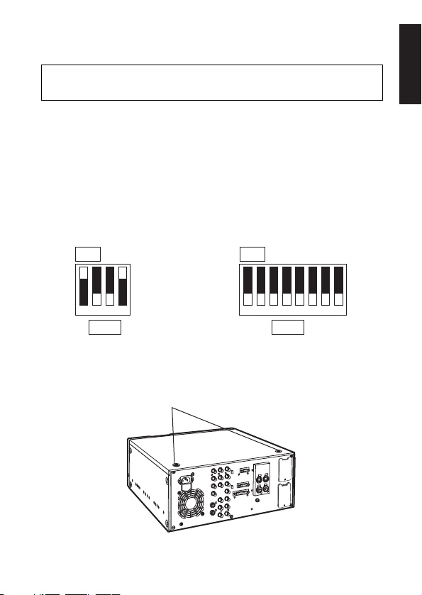
Coin screws
2.
Check that the DIP switches on the AJ-YAD455P are
set to the positions shown in the figure below.
SW-1
ON
1234567
8
SW-2
ON
123
4
Installation in AJ-D455
3.
Remove the 2 coin screws and top panel from the unit.
1.
Disconnect the power cord from the unit.
Consult your dealer concerning the installation of
the digital video interface board.
Page 6
5(E)
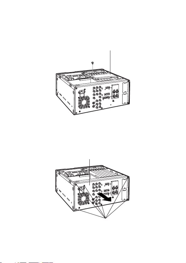
Screw
Screws
Board clamp
Rear panel
Installation in AJ-D455
4.
Remove the screw and the board clamp.
5.
Remove the 6 screws and pull the rear panel directly
backwards to remove.
Page 7

6(E)
ENGLISH
Screw
Connector board
Screw
Blank panel
Installation in AJ-D455
6.
Remove the screw and remove the blank panel from the
rear panel.
7.
Attach the accessory connector board to the rear panel.
Pass the wiring through the rear panel, attach the top
side of the connector board and secure the lower side
of the board in place with the screw, as shown in the
diagram below.
Page 8

7(E)
9.
Insert the interface board into the front panel side of the
slot marked “F3”.
Installation in AJ-D455
F3
Clampers
View from rear
8.
Pass the wiring through the unit and secure the rear
panel with the 6 screws. Ensure that wiring and
connections are as shown in the respective diagrams
below.
Connections DiagramWiring Diagram
Page 9

8(E)
ENGLISH
Installation in AJ-D455
Screw
Coin screws
Board clamp
10.
Attach the board clamp with the screw and secure the
top panel to the unit with the 2 coin screws.
Page 10

9(E)
<Note>
O
With some types of recording tapes, the input data format
is converted automatically.
AJ-D455 settings
Recording tape
DVCPRO
DV
Input data Recording format
DVCPRO DVCPRO
DV
DVCPRO
DV
DV
DV
DVCPRO (
2
1)
2
1: “CH1/CH2” or “CH3/CH4” can be selected by setup
menu item No.889 (DIF AUD IN) when 32 KHz/4CH
audio data is input.
1.
Check that the setup menu item No.220 (AV/C CMD
SEL) is set to “ON.”
3.
When inputting signals from the digital video interface
board, set the VIDEO IN switch on the front panel to
“DV/DVCPRO.”
2.
Check that “AUTO” has been selected as the setup
menu item No.882 (DIF IN CH) and No.883 (DIF OUT
CH) settings.
NTSC regions
Page 11

10(E)
ENGLISH
AJ-D455 settings
<Note>
O
The output data format can be converted by setting the
setup menu item No.881 (DIF TYPE).
DIF TYPE setting
DVCPRO
DV
Playback tape Output format
DVCPRO DVCPRO
DV
DVCPRO
DV
DV
DV
AUTO
DVCPRO
DV
DVCPRO
DV
DVCPRO (
2
2)
2
2: “CH1/CH2” or “CH3/CH4” can be selected by setup
menu item No.890 (DIF AUD OUT) when the 32 KHz/
4CH audio signals are recorded on the playback tape.
NTSC regions
Page 12

11(E)
<Note>
O
When the recording tape is in the DVCPRO format, DV
format input data cannot be received or recorded.
Similarly, when it is in the DV format, DVCPRO format
input data cannot be received or recorded.
AJ-D455 settings
PAL regions
1.
Check that the setup menu item No.220 (AV/C CMD
SEL) is set to “ON.”
3.
When inputting signals from the digital video interface
board, set the VIDEO IN switch on the front panel to
“DV/DVCPRO.”
2.
Check that “AUTO” has been selected as the setup
menu item No.882 (DIF IN CH) and No.883 (DIF OUT
CH) settings.
Recording tape
DVCPRO
DV
Input data Recording format
DVCPRO DVCPRO
DV
DVCPRO
DV
Receiving and recording
of data not possible.
DV
Receiving and recording
of data not possible.
Page 13

12(E)
ENGLISH
O
Connect the AJ-YAD455P with other units in a 1:1 format.
O
Use the special-purpose cable (AJ-DTC2P or AJ-DTC4P)
to connect the AJ-YAD455P with the AJ-D455, AJ-D250
or AJ-D230H.
O
Turning the power of the connected units ON or OFF or
connecting or disconnecting the interface cable may
disrupt the AV signals.
O
It may take some moments for the system to stabilize
when the input signals have been switched or when
operation has been transferred to another mode.
Proceed with recording operations after the system has
stabilized.
O
When the digital video interface input has been selected
for recording, the AUDIO REC LEVEL control on the front
panel will not work.
O
When the AJ-D455 is used as the recorder VTR, insert
and assemble editing using the digital video interface
input cannot be performed.
O
When the signals from slow mode playback are input
using the digital video interface and then recorded, the
audio signals will be recorded as muted.
O
CUE signals cannot be transmitted with the digital video
interface. It is also not possible to record multiplex audio
signals on the CUE track.
Precautions for use
Page 14

13(E)
Item Setting
220 AV/C
CMD
SEL
0000
0001
OFFONFor selecting whether to use the
digital video interface AV/C
command when the
REMOTE/LOCAL switch is at the
REMOTE position.
0: The AV/C command is not used.
1: The AV/C command is used.
For setting the format used for
output.
0: The format is forcibly set to
DVCPRO for output.
1: The format is forcibly set to DV
for output.
2: The same format as that of the
playback tape is set.
881 DIF
TYPE
(21)
0000
0001
0002
DVCPRO
DV
AUTO
No.
Superimposed
display
Superimposed
display
No.
Description of settings
The underlining indicates the factory setting.
21: This item does not appear with the PAL system.
Setup menus
The following setup menu items can be used when the AJYAD455P has been installed in the AJ-D455.
882 DIF
IN
CH
0000
[
0063
0064
0
[
63
AUTO
For setting the input channels.
0-63: These are fixed at designated
values.
64: This is not fixed at a designated
value. It is initialized to 63
when the power is turned on or
when the cable is connected or
disconnected.
Page 15

14(E)
ENGLISH
Item
Setting
883 DIF
OUT
CH
0000
[
0063
0064
0
[
63
AUTO
For setting the output channels.
0-63: These are fixed at designated
values.
64: This is not fixed at a designated
value. It is initialized to 63 when
the power is turned on or when
the cable is connected or
disconnected.
Expansion menu
Normally, the “DFLT” setting is used
for this item. For further details,
consult your dealer.
886
DIF
CONFIG
0000
0001
[
0255
DFLT
1
[
255
No.
Superimposed
display
Superimposed
display
No.
Description of settings
The underlining indicates the factory setting.
889
890 DIF
AUD
OUT
(21)
0000
0001
CH1&2
CH3&4
DIF
AUD
IN
(21)
0000
0001
CH1&2
CH3&4
For selecting the channels whose
audio signals will be recorded on the
tape when a 4-channel audio mode
DV format data is to be received and
recorded onto a DVCPRO tape.
0: CH1 and CH2 of the DV format
data received are selected.
1: CH3 and CH4 of the DV format
data received are selected.
For selecting the channels of the
audio signals when a 4-channel
audio mode DV tape is to be played
back and the signals are to be output
in the DVCPRO format.
0: CH1 and CH2 of the DV tape are
selected.
1: CH3 and CH4 of the DV tape are
selected.
Setup menus
21: This item does not appear with the PAL system.
Page 16

15(E)
DIAG menu
By installing the AJ-YAD455P in the AJ-D455, a DIAG menu
screen showing information relating to the digital video
interface is additionally provided.
For details on the DIAG menu display method, refer to the
operating instructions of the AJ-D455.
Item
EUI-64
Description
Indicates the NODE UNIQUE ID of this unit.
Indicates the number of local bus connections.
Indicates the current PHY ID of this unit.
Indicates the PHY ID of the root on the local path.
Indicates the PHY ID of the Isochronous Resource
Manager.
Indicates the current input channel number.
Indicates the current output channel number.
Indicates the current transfer rate.
Indicates the current gap count value.
Indicates the input/output status.
Indicates the format of the data received or
transmitted.
Indicates the NTSC or PAL information of the data
received or transmitted.
Indicates the video information of the data received
or transmitted.
Indicates the audio information of the data received
or transmitted.
NODE CNT
MY ID
ROOT ID
IRM ID
IN-CH
OUT-CH
DIF SPEED
GAP CNT
STA
DIF
N/P
VIDEO
AUDIO
Page 17

16(E)
ENGLISH
The signals which have been input from
the digital video interface have neither
the DVCPRO nor DV format.
Warning messages
By installing the AJ-YAD455P in the AJ-D455, the following
warning messages are additionally provided.
These messages will appear on the mode display when
“T&S&M” has been selected as the setup menu item No.003
(DISPLAY SEL) setting.
Display on
monitor screen
(counter display)
UNKNOWN
SIG (E-04)
Description Operation
21
21
22
23
The compressed video signals which
have been input from the digital video
interface are invalid.
The audio signals which have been input
from the digital video interface are
invalid.
The time code information contained in
the signals which have been input from
the digital video interface is invalid.
INVALID VIDEO
SIG (E-16)
INVALID AUDIO
SIG (E-17)
INVALID TC SIG
(E-18)
24
The copy protect information which has
been input from the digital video
interface is copy protected when a DV
cassette has been inserted.
COPY
PROTECTED
(E-91)
21: This warning is displayed only during recording operations. When it
appears, the video signals are recorded as blank burst and the audio
signals are recorded as muted.
22: This warning is displayed only during recording operations. When it
appears, the audio signals are recorded as muted.
23: This warning is displayed only during recording operations. When it
appears, the internally generated time code is recorded.
24: This warning is displayed at all times. When it appears, a recording
operation cannot be initiated from any mode other than recording. When
it appears during a recording operation, the mode is transferred to stop.
Page 18

Printed in Japan
VQT9174
S0401Y
@
j i
PANASONIC BROADCAST & TELEVISION SYSTEMS COMPANY
DIVISION OF MATSUSHITA ELECTRIC CORPORATION OF AMERICA
Executive Office:
3330 Cahuenga Blvd W., Los Angeles, CA 90068 (323) 436-3500
EASTERN ZONE:
One Panasonic Way 4E-7, Secaucus, NJ 07094 (201) 348-7621
Southeast Region:
1225 Northbrook Parkway, Ste 1-160, Suwanee, GA 30024 (770) 338-6835
Central Region:
1707 N Randall Road E1-C-1, Elgin, IL 60123 (847) 468-5200
WESTERN ZONE:
3330 Cahuenga Blvd W., Los Angeles, CA 90068 (323) 436-3500
Government Marketing Department:
52 West Gude Drive, Rockville, MD 20850 (301) 738-3840
Broadcast PARTS INFORMATION & ORDERING:
9:00 a.m. – 5:00 p.m. (EST) (800) 334-4881/24 Hr. Fax (800) 334-4880
Emergency after hour parts orders (800) 334-4881
TECHNICAL SUPPORT:
Emergency 24 Hour Service (800) 222-0741
Panasonic Canada Inc.
5770 Ambler Drive, Mississauga, Ontario L4W 2T3 (905) 624-5010
Panasonic de Mexico S.A. de C.V.
Av angel Urraza Num. 1209 Col. de Valle 03100 Mexico, D.F. (52) 1 951 2127
Panasonic Sales Company
Division of Matsushita Electric of Puerto Rico Inc.
San Gabriel Industrial Park, 65th Infantry Ave., Km. 9.5, Carolina, Puerto Rico
00630 (787) 750-4300
Panasonic Broadcast Europe
Panasonic Broadcast Europe Ltd
West Forest Gate, Wellington Road, Wokingham, Berkshire RG40 2AQ U.K.
Tel: 0118 902 9200
Page 19

documentation manual, user maintenance, brochure, user reference, pdf manual
This file has been downloaded from:
User Manual and User Guide for many equipments like mobile phones, photo cameras, monther board, monitors, software, tv, dvd, and othes..
Manual users, user manuals, user guide manual, owners manual, instruction manual, manual owner, manual owner's, manual guide,
manual operation, operating manual, user's manual, operating instructions, manual operators, manual operator, manual product,
 Loading...