


AJ- P
SDTI Interface Board
Operating Instructions

2
The AJ-YAC150P is an SDTI interface board for the
AJ-HD150. Consult your dealer before attempting
to install it into the AJ-HD150.
O Do not touch this product with wet hands.
O Do not drop this product or subject it to strong impact.
O Do not remodel this product. Doing so may cause
malfunctioning.
AJ-YAC150P main unit
The AJ-YAC150P is an SDTI interface board for the AJHD150.
By installing this board into the AJ-HD150, it is possible to
input and output digital data using the SDTI format
21
(compression digital interface).
21
SDTI (Serial Data Transport Interface) complies with the
SMPTE305M standard.
The data stream format complies with the SMPTE312M
standard.
Connection area
Serial digital input connector (BNCt1)
1. Input: Dedicated SDTI input
Serial digital output connector (BNCt1)
2. Output: Dedicated SDTI output
Cautions
Features
HD SDI
IN
IN
(OPTION)
OUT
HD SDTI
OUT 1
OUT 2
OUT 3
(SUPER)

3
Cautions . . . . . . . . . . . . . . . . . . . . . . . . . . . . . . . . . . . . . . .
2
Features . . . . . . . . . . . . . . . . . . . . . . . . . . . . . . . . . . . . . . .
2
Specifications . . . . . . . . . . . . . . . . . . . . . . . . . . . . . . . . . .
4
Installing the AJ-YAC150P board. . . . . . . . . . . . . . . . . . .
5
SDTI input operations . . . . . . . . . . . . . . . . . . . . . . . . . . .
11
SDTI output operations . . . . . . . . . . . . . . . . . . . . . . . . . .
13
Precautions for using SDTI. . . . . . . . . . . . . . . . . . . . . . .
15
Setup menu . . . . . . . . . . . . . . . . . . . . . . . . . . . . . . . . . . .
17
Warning messages . . . . . . . . . . . . . . . . . . . . . . . . . . . . .
18
Contents

4
$ Main unit
Dimensions (WtHtD):
6˝t5-7/8˝t13/16˝ (152t148t20 mm)
Weight:
0.5126 lb (233 g)
$ Video audio input connector
Serial digital input connector:
BNCt1
SDTI IN: Dedicated SDTI input connector
Compliant with SMPTE305M/SMPTE321M standards.
$ Video audio output connector
Serial digital output connector:
BNCt1
SDTI OUT: Dedicated SDTI output connector
Compliant with SMPTE305M/SMPTE321M standards.
Specifications

5
This board must be installed in the AJ-HD150 in order for it
to be used. Follow the procedure described below.
Installing the AJ-YAC150P board
1.
Disconnect the power cord from the main unit.
Consult your dealer before attempting to install the
digital video interface board.
The software versions for the VTR unit need to be
upgraded. Check to see if the proper versions are
running.
AV DV REC Ver.1.07 and up
DV PB Ver.1.03 and up
I/F Ver.1.04 and up
FRONT Ver.1.02 and up
SYSCON Ver.1.05 and up
SERVO Ver.1.03 and up
2.
Remove the two coin screws to remove the top panel
from the main unit.
Coin screws

6
Screws
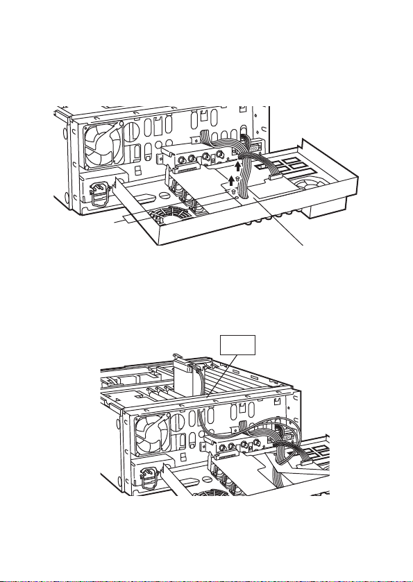
Installing the AJ-YAC150P board
4.
Remove the nine screws to remove the rear panel.
<Note>
T
Exercise caution when handling the bundled wires
from the main unit side.
3.
Remove the two screws to remove the board clamp.
Screws
Board clamp
7
H2
Screws
Connector clamp
Installing the AJ-YAC150P board
5.
Remove the two screws, then remove the connector
clamp on the rear panel.
6.
Pass the two coaxial cables through the holes in the
side of the slot marked “H2” on the main unit side to the
rear panel end.

8
Installing the AJ-YAC150P board
Green
Orange
7.
Connect the coaxial cables to the BNC connectors
specified on the rear panel.
<Notes>
T
Take care not to disconnect the cables which have
already been attached.
T
Pass the cables through the hole in the connector
clamp, and connect them.
T
Bundle the cables together using the binder which is
packed with the board.

9
Installing the AJ-YAC150P board
9.
Insert the SDTI board into the opening marked “H2” on
the main unit side, and attach the rear panel using the
nine screws.
8.
Attach the connector clamp on the rear panel using the
two screws.
<Note>
T
Take care not to pinch the cables between the
connectors and connector clamp.
H2
Connector clamp
Screws

10
10.
Attach the board clamp using the two screws, and
secure the top panel to the main unit using the two
coin screws.
Screws
Coin screws
Board clamp
Installing the AJ-YAC150P board

11
SDTI input operations
SDTI input connector
This connector is used exclusively for SDTI input signals.
To select SDTI as the input
Select SDTI as the menu item No.600 (VIDEO IN SEL)
setting.
To select the time code
To select the time code of the SDTI input signal, set the
TC INT/EXT switch to EXT, and select SLTC or SVITC as
the menu item No.507 (EXT TC SEL) setting.
<Notes>
O When SDTI has been selected as the input signal, the
SDTI signal is selected for both the audio and video
signals.
O No adjustments can be performed for the audio and video
signals in the SDTI input signals.
O Only SDTI signals in the DVCPRO HD (100 Mbps) format
selected by menu item No.020 (SYS FORMAT) can be
recorded. However, no guarantees can be made either
for the recordings made when playback signals at a
speed other than the normal (x1) speed are input or for
EE pictures. (The sound is muted.)

12
SDTI input operations
Formats supporting signal reception
(When the setting for SYS FORMAT at the receiving deck
matches the format selected for the data to be transmitted)
Sending
Receiving
AUDIO output
signals
VIDEO output
signals
Signals
can be
recorded
DVCPRO HD x1 speed
playback
ON
AUDIO CH SELECT
SHIFT ADJ
TC SET
START
TC/CTL
RESET
TC INTTCTAPE
UB
STAND BY
EDIT PLAY
REW STOP
SERVO
REC
FF
REC INHIBIT
PLAYER
EXT EE
MODE
REMOTE
PUSH
REV FWD
RECORDER
LOCAL
CONTROL
CH 1
1
ASMBL
PREVIEW
REVIEW
AUTO EDIT
PREROLL
TRIM
A
IN
IN
SET OUT
A
OUT
MULTICUE
INSERT
VIDEO
CH1/5CH2/8 CH3/7CH4/8 CUE TC
CH 4
OFF
POWER
CH CONDITION ENTERESCAPE SHIFT
METER
FULL/FINE
MONITOR SELECT
LEVEL
HEADPHONES
CH 1/5 CH 2/6 CH 3/7 CH 4/8 CUE
REC
L
R
PB
PULL FOR VARIABLE
PULL
OPEN
PULL
OPEN
CH 5CH 8
2 3 45 6 7 8
JOG SHTL
SLOW
EJECT
M-cassette / ADAPTER
Caution: Do not insert S-cassette without adapter
DVCPRO
32
SDTI
MonitorSpeaker
(AJ-HD150
with SDTI)
(AJ-HD150
with SDTI)

13
SDTI output operations
SDTI output connector
This connector is used exclusively for SDTI output signals.
<Notes>
O When playing back a tape in the DVCPRO (25 Mbps),
DVCPRO50 (50 Mbps), DVCPRO P (50 Mbps) or
DVCPRO HD (100 Mbps) format, the signals will be
output in the same format as the one in which the
recording was made on the tape.
O DV compressed signals (see
21
) will be output as the
SDTI output signals when a DV or DVCAM format tape is
played back.
O No adjustments can be performed for the audio and video
signals in the SDTI output signals.
O During SLOW/STILL playback, unprocessed audio and
video signals will be output as the SDTI output signals. If
these audio and video signals are monitored on another
component, they may differ from the audio and video
signals which are played back on the AJ-DH150.
O SDTI signals are not output when the field frequency is
60 Hz.
21
These signals comply with the IEC6134-2 standard.

14
ON
AUDIO CH SELECT
SHIFT ADJ
TC SET
START
TC/CTL
RESET
TC INTTCTAPE
UB
STAND BY
EDIT PLAY
REW STOP
SERVO
REC
FF
REC INHIBIT
PLAYER
EXT EE
MODE
REMOTE
PUSH
REV FWD
RECORDER
LOCAL
CONTROL
CH 1
1
ASMBL
PREVIEW
REVIEW
AUTO EDIT
PREROLL
TRIM
A
IN
IN
SET OUT
A
OUT
MULTICUE
INSERT
VIDEO
CH1/5CH2/8 CH3/7CH4/8 CUE TC
CH 4
OFF
POWER
CH CONDITION ENTERESCAPE SHIFT
METER
FULL/FINE
MONITOR SELECT
LEVEL
HEADPHONES
CH 1/5 CH 2/6 CH 3/7 CH 4/8 CUE
REC
L
R
PB
PULL FOR VARIABLE
PULL
OPEN
PULL
OPEN
CH 5CH 8
2 3 45 6 7 8
JOG SHTL
SLOW
EJECT
M-cassette / ADAPTER
Caution: Do not insert S-cassette without adapter
SDTI output operations
Formats supporting signal transmission
AJ-HD150
with SDTI
SDTIx1 speed playback
DVCPRO50
DVCPRO
DVCPRO50
DVCPRO P
21
DVCPRO
DVCPRO
DVCPRO
32
DVCPRO
64
DVCPRO
96
ON
AUDIO CH SELECT
SHIFT ADJ
TC SET
START
TC/CTL
RESET
TC INTTCTAPE
UB
STAND BY
EDIT PLAY
REW STOP
SERVO
REC
FF
REC INHIBIT
PLAYER
EXT EE
MODE
REMOTE
PUSH
REV FWD
RECORDER
LOCAL
CONTROL
CH 1
1
ASMBL
PREVIEW
REVIEW
AUTO EDIT
PREROLL
TRIM
A
IN
IN
SET OUT
A
OUT
MULTICUE
INSERT
VIDEO
CH1/5CH2/8 CH3/7CH4/8 CUE TC
CH 4
OFF
POWER
CH CONDITION ENTERESCAPE SHIFT
METER
FULL/FINE
MONITOR SELECT
LEVEL
HEADPHONES
CH 1/5 CH 2/6 CH 3/7 CH 4/8 CUE
REC
L
R
PB
PULL FOR VARIABLE
PULL
OPEN
PULL
OPEN
CH 5CH 8
2 3 45 6 7 8
JOG SHTL
SLOW
EJECT
M-cassette / ADAPTER
Caution: Do not insert S-cassette without adapter
AJ-D960
with SDTI
ON
AUDIO CH SELECT
SHIFT ADJ
TC SET
START
TC/CTL
RESET
TC INTTCTAPE
UB
STAND BY
EDIT PLAY
REW STOP
SERVO
REC
FF
REC INHIBIT
PLAYER
EXT EE
MODE
REMOTE
PUSH
REV FWD
RECORDER
LOCAL
CONTROL
CH 1
1
ASMBL
PREVIEW
REVIEW
AUTO EDIT
PREROLL
TRIM
A
IN
IN
SET OUT
A
OUT
MULTICUE
INSERT
VIDEO
CH1/5CH2/8 CH3/7CH4/8 CUE TC
CH 4
OFF
POWER
CH CONDITION ENTERESCAPE SHIFT
METER
FULL/FINE
MONITOR SELECT
LEVEL
HEADPHONES
CH 1/5 CH 2/6 CH 3/7 CH 4/8 CUE
REC
L
R
PB
PULL FOR VARIABLE
PULL
OPEN
PULL
OPEN
CH 5CH 8
2 3 45 6 7 8
JOG SHTL
SLOW
EJECT
M-cassette / ADAPTER
Caution: Do not insert S-cassette without adapter
AJ-PD950
AJ-D950
with SDTI
ON
AUDIO CH SELECT
SHIFT ADJ
TC SET
START
TC/CTL
RESET
TC INTTCTAPE
UB
STAND BY
EDIT PLAY
REW STOP
SERVO
REC
FF
REC INHIBIT
PLAYER
EXT EE
MODE
REMOTE
PUSH
REV FWD
RECORDER
LOCAL
CONTROL
CH 1
1
ASMBL
PREVIEW
REVIEW
AUTO EDIT
PREROLL
TRIM
A
IN
IN
SET OUT
A
OUT
MULTICUE
INSERT
VIDEO
CH1/5CH2/8 CH3/7CH4/8 CUE TC
CH 4
OFF
POWER
CH CONDITION ENTERESCAPE SHIFT
METER
FULL/FINE
MONITOR SELECT
LEVEL
HEADPHONES
CH 1/5 CH 2/6 CH 3/7 CH 4/8 CUE
REC
L
R
PB
PULL FOR VARIABLE
PULL
OPEN
PULL
OPEN
CH 5CH 8
2 3 45 6 7 8
JOG SHTL
SLOW
EJECT
M-cassette / ADAPTER
Caution: Do not insert S-cassette without adapter
AJ-D850
with SDTI
ON
AUDIO CH SELECT
SHIFT ADJ
TC SET
START
TC/CTL
RESET
TC INTTCTAPE
UB
STAND BY
EDIT PLAY
REW STOP
SERVO
REC
FF
REC INHIBIT
PLAYER
EXT EE
MODE
REMOTE
PUSH
REV FWD
RECORDER
LOCAL
CONTROL
CH 1
1
ASMBL
PREVIEW
REVIEW
AUTO EDIT
PREROLL
TRIM
A
IN
IN
SET OUT
A
OUT
MULTICUE
INSERT
VIDEO
CH1/5CH2/8 CH3/7CH4/8 CUE TC
CH 4
OFF
POWER
CH CONDITION ENTERESCAPE SHIFT
METER
FULL/FINE
MONITOR SELECT
LEVEL
HEADPHONES
CH 1/5 CH 2/6 CH 3/7 CH 4/8 CUE
REC
L
R
PB
PULL FOR VARIABLE
PULL
OPEN
PULL
OPEN
CH 5CH 8
2 3 45 6 7 8
JOG SHTL
SLOW
EJECT
M-cassette / ADAPTER
Caution: Do not insert S-cassette without adapter
21
The DVCPRO P format is used only with the AJ-PD950.
Sending
(AJ-HD150 with SDTI)
DVCPRO HD

15
Bear in mind the following precautions when using SDTI.
O It is possible to conduct recording operations for the SDTI
input signals but only for transmission at the x1 speed
and only in the DVCPRO HD (100 Mbps) format which
has been selected as the menu item No.020 (SYS
FORMAT) setting.
O Editing operations involving the SDTI cannot be
performed.
O SDTI dubbing cannot be conducted for tapes recorded in
the DV or DVCAM format.
O Cue signals cannot be transmitted using SDTI. To dub
them, connect a separate cable for use with these
signals. In this case, the selection established by the
menu item No.730 (REC CUE) setting is rendered invalid,
and the setting is fixed at the cue signal input.
O No guarantees are made for the video signal output when
a tape on which SLOW playback signals have been input
by SDTI and recorded is replayed in the SLOW mode.
(The sound is muted.)
Precautions for using SDTI

16
Precautions for using SDTI
Source Recorder
SDTI signals
Cue signals (when cue
signals are to be dubbed)
SD_REFsignal
HD_REFsignal
Reference signal
generator
Connections using two AJ-HD150 units

17
<Note>
O When SDTI has been selected as the setup menu item
No.600 (VIDEO IN SEL) setting, the selection established
by the menu item No.700 (AUDIO IN SEL) setting is
rendered invalid, and the audio setting is also fixed at the
SDTI input.
Item Setting
600 VIDEO
IN
SEL
0000
0001
0002
INT SG
SDI
SDTI
For selecting the (video) signal
which is to be input.
0: The internal signal selected by
VIDEO INT SG is generated.
1: The serial video signal which has
been input to the HD SDI IN
connector is selected.
2: The serial compressed signal
which has been input to the SDTI
IN connector is selected.
No.
Superimposed
display
No.
Superimposed
display
Description of setting
The underlining above indicates the factory settings.
USER menu
<VIDEO>
Setup menu
When the board is installed in the VTR, the setup menu
shown below can be used.

18
This message appears when the
SDTI input signals are not in the
DVCPRO or DV format.
Warning messages
The following warning messages will be additionally
provided when the board has been installed in the VTR.
They are indicated on the mode display when “T&S&M” has
been selected as the setup menu item No.006 (DISPLAY
SEL) setting.
Monitor screen
display
(counter display)
UNKNOWN
SIG
Description Operation
Recording operations cannot be
performed.
Operation
continues.
(See 21)
Operation
continues.
(See 22)
Operation
continues.
(See 23)
This message appears when the
compressed video signals in the
SDTI input signals are irregular
signals.
This message appears when the
audio signals in the SDTI input
signals are irregular signals.
This message appears when the
time code signal in the SDTI input
signals is an irregular signal.
INVALID VIDEO
SIG
INVALID AUDIO
SIG
INVALID TC SIG
Recording operations cannot be
performed.
This message appears when the
format of the SDTI input signals
does not match the SYS format.
NO MATCH
SIG
Recording operations cannot be
performed.
This message appears when the
SDTI input signals are not x1 speed
transfer signals in the DVCPRO HD
(100 Mbps) format.
NOT1tt100M
SIG
21 This warning appears only when a recording operation is in progress.
When it appears, nothing will be recorded on the tape and only the
erasure operation will be performed.
22 This warning appears only when a recording operation is in progress.
When it appears, the audio signals will be muted and recorded.
23 This warning appears only when a full EE operation with the REC button
pressed is in progress.


PANASONIC BROADCAST & TELEVISION SYSTEMS COMPANY
DIVISION OF MATSUSHITA ELECTRIC CORPORATION OF AMERICA
Executive Office:
3330 Cahuenga Blvd W., Los Angeles, CA 90068 (323) 436-3500
EASTERN ZONE:
One Panasonic Way 4E-7, Secaucus, NJ 07094 (201) 348-7621
Southeast Region:
1225 Northbrook Parkway, Ste 1-160, Suwanee, GA 30024 (770) 338-6835
Central Region:
1707 N Randall Road E1-C-1, Elgin, IL 60123 (847) 468-5200
WESTERN ZONE:
3330 Cahuenga Blvd W., Los Angeles, CA 90068 (323) 436-3500
Government Marketing Department:
52 West Gude Drive, Rockville, MD 20850 (301) 738-3840
Broadcast PARTS INFORMATION & ORDERING:
9:00 a.m. – 5:00 p.m. (EST) (800) 334-4881/24 Hr. Fax (800) 334-4880
Emergency after hour parts orders (800) 334-4881
TECHNICAL SUPPORT:
Emergency 24 Hour Service (800) 222-0741
Panasonic Canada Inc.
5770 Ambler Drive, Mississauga, Ontario L4W 2T3 (905) 624-5010
Panasonic de Mexico S.A. de C.V.
Av angel Urraza Num. 1209 Col. de Valle 03100 Mexico, D.F. (52) 1 951 2127
Panasonic Sales Company
Division of Matsushita Electric of Puerto Rico Inc.
San Gabriel Industrial Park, 65th Infantry Ave., Km. 9.5, Carolina, Puerto Rico
00630 (787) 750-4300

documentation manual, user maintenance, brochure, user reference, pdf manual
This file has been downloaded from:
User Manual and User Guide for many equipments like mobile phones, photo cameras, monther board, monitors, software, tv, dvd, and othes..
Manual users, user manuals, user guide manual, owners manual, instruction manual, manual owner, manual owner's, manual guide,
manual operation, operating manual, user's manual, operating instructions, manual operators, manual operator, manual product,
 Loading...