

Panasonic aj-yad250 Operation Manual
AJ- P
Digital Video Interface Board
Operating Instructions
ENGLISHFRANÇAIS
E– 1
This digital video interface board is designed to be used
exclusively with the model AJ-D250 digital VTR. It cannot
be used with model AJ-D230 or AJ-D230H.
For details concerning its installation in the model AJD250, consult your dealer.
Precautions
ODo not touch the product with wet hands.
ODo not drop the product or expose it to bumps or shocks.
ODo not attempt to modify the product.
Doing so could cause it to malfunction.
Model supported
Digital VTR: AJ-D250
CAUTION:
TO REDUCE THE RISK OF FIRE OR SHOCK
HAZARD, REFER MOUNTING OF THE OPTIONAL
INTERFACE BOARD TO AUTHORIZED SERVICE
PERSONNEL.
indicates safety information.

E– 2
ENGLISH
Contents
Precautions . . . . . . . . . . . . . . . . . . . . . . . . . . . . . . . . . . .
E– 1
Model supported . . . . . . . . . . . . . . . . . . . . . . . . . . . . . . .
E– 1
Features . . . . . . . . . . . . . . . . . . . . . . . . . . . . . . . . . . . . .
E– 2
Specifications . . . . . . . . . . . . . . . . . . . . . . . . . . . . . . . . .
E– 3
RS-232C hardware specifications. . . . . . . . . . . . . . . . . .
E– 4
Checking the software version . . . . . . . . . . . . . . . . . . . .
E– 5
Installing the board in an AJ-D250 . . . . . . . . . . . . . . . . .
E– 6
Equipment connections . . . . . . . . . . . . . . . . . . . . . . . . .
E– 11
AJ-D250 settings . . . . . . . . . . . . . . . . . . . . . . . . . . . . . .
E– 14
Superimposed display screen . . . . . . . . . . . . . . . . . . . .
E– 15
AJ-D250 set-up menus . . . . . . . . . . . . . . . . . . . . . . . . .
E– 16
AJ-D250 VTR modes and input/output statuses . . . . . .
E– 19
RS-232C . . . . . . . . . . . . . . . . . . . . . . . . . . . . . . . . . . .
E– 23
Error Messages . . . . . . . . . . . . . . . . . . . . . . . . . . . . . .
E– 29
Features
This product is a digital video interface board which is designed
exclusively for use in the AJ-D250 VTR.
Installing this board in the AJ-D250 creates an environment in
which AV signals or time codes can be transmitted digitally
between AJ-D250 units. (Compliant with IEEE1394-1995
standard.)
An RS-232C connector (9-pin) is provided as a standard
accessory.
RS-232C control is enabled using the accessory 9-pin/25-pin
conversion connector.
E– 3
Specifications
$
Digital video interface board
Dimensions (WaHaD) :
6 3/16˝a4 3/16˝a1 1/16˝ (157a105a26 mm)
Weight : 0.3036 lb (138 g)
Power consumption : 2 W
O
Items packed with board
Display label
9-pin/25-pin conversion connector
Hexagonal head screws (for metric screw threads)
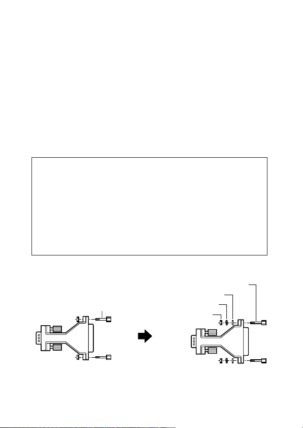
Concerning which hexagonal head screws are to be
used
The accessory 9-pin/25-pin conversion connector comes
with two hexagonal head screws for inch-standard screw
threads.
If metric screw threads are used by the device which is to
be connected, replace the hexagonal head screws with the
ones with metric screw threads which are also packed
together with the connector.
Hexagonal head screws
(for inch-standard screw
threads)
Hexagonal head screws
(for metric screw threads)
Plain washer
Spring lock washer
Hexagonal nut
E– 4
ENGLISH
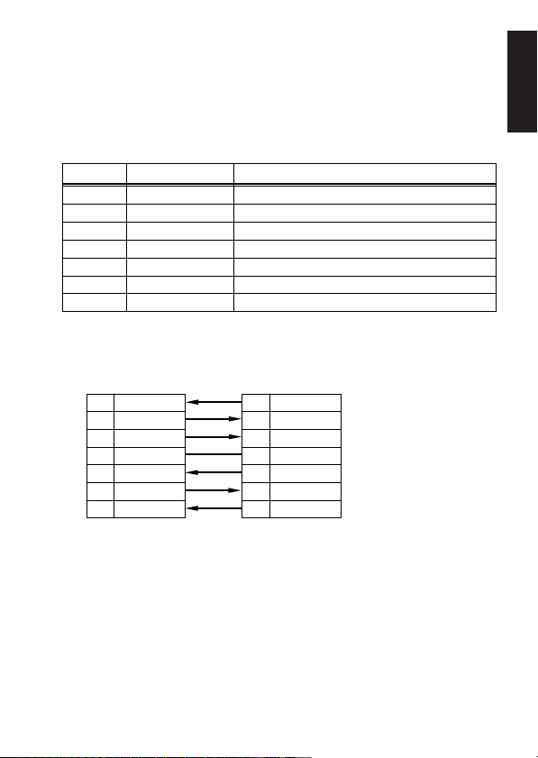
RS-232C hardware specifications
External interface specifications
Connector:
D-SUB, 9 pins, DCE specifications (straight cable supported)
For details on other specifications relating to RS-232C, refer to
the operating instructions of the AJ-D250.
Pin No. Signal Description
2 RD (RXD) Received data
3 SD (TXD) Transmitted data
4 ER (DTR) Data terminal ready
5 SG (GND) Signal ground
6 DR (DSR) Data set ready
7 RS (RTS) Request to send
8 CS (CTS) Clear to send
2 RD (RXD)
3 SD (TXD)
4 ER (DTR)
5 SG (GND)
6 DR (DSR)
7 RS (RTS)
8 CS (CTS)
2 RD (RXD)
3 SD (TXD)
4 ER (DTR)
5 SG (GND)
6 DR (DSR)
7 RS (RTS)
8 CS (CTS)
Example of wiring connections
Personal computer side
(D-SUB, 9-pin connector)
VTR side
E– 5
IF : 1.04-00-0.00
AVSYS : 1.06-00-0.00
:
:
:
:
Checking the software version
Check the software version of the AJ-D250 before installing the
AJ-YAD250P in the AJ-D250.
If it is an old version, it must be upgraded.
Please consult your dealer.
How to check to the software version
1.
Connect a monitor to the AJ-D250.
2.
Set the LOCAL/MENU/REMOTE switch to the MENU
position while pressing the EJECT button on the front
panel of the AJ-D250.
3.
Press the FF (UP) button while pressing the REW
(MODE) button.
4.
The software version now appears on the monitor
screen.
<Note>
The current version supports models with the IF
and AVSYS numbers indicated above or higher.
If the figures are lower (signifying that the version is
an old one), the current version must be upgraded.
E– 6
ENGLISH
Installing the board in an AJ-D250
In order for this product to be used, it must first be installed in
an AJ-D250. Follow the installation procedure below.
O
Always be absolutely sure to disconnect the AJ-D250’s
power cord before proceeding with installation.
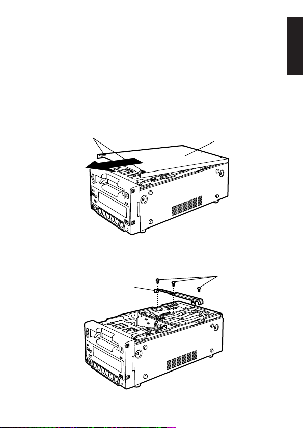
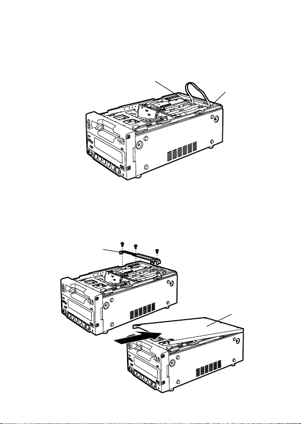
1.
Remove the two screws on the top panel of the AJ-D250,
and slide it toward the front panel to remove it.
2.
Remove the three screws and remove the board clamp.
Screws
Board clamp
Top panel
Screws
E– 7
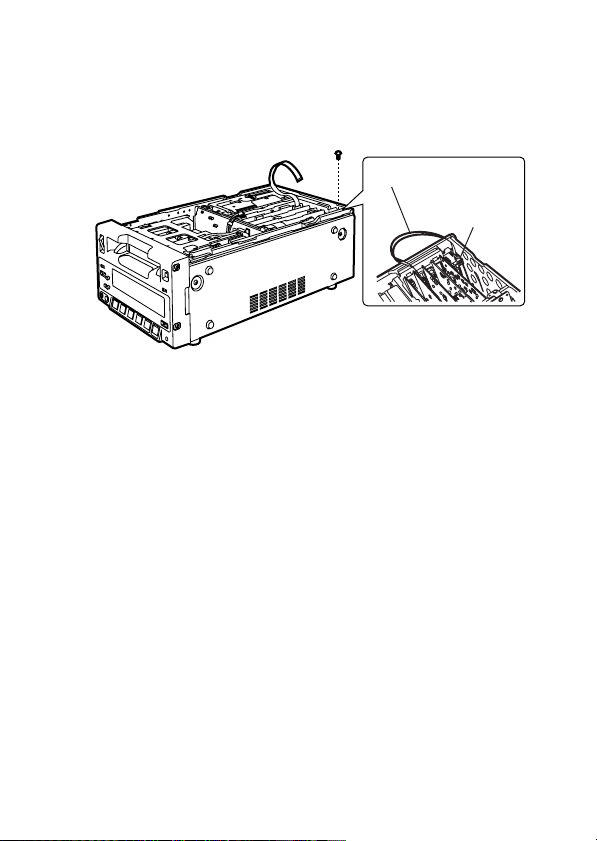
3.
Disconnect the flat cable from the connector (P6001) on
the RS-232C board, and remove the mounting screw to
remove the RS-232C board.
Mounting screw
Flat cable
RS-232C
board
E– 8
ENGLISH
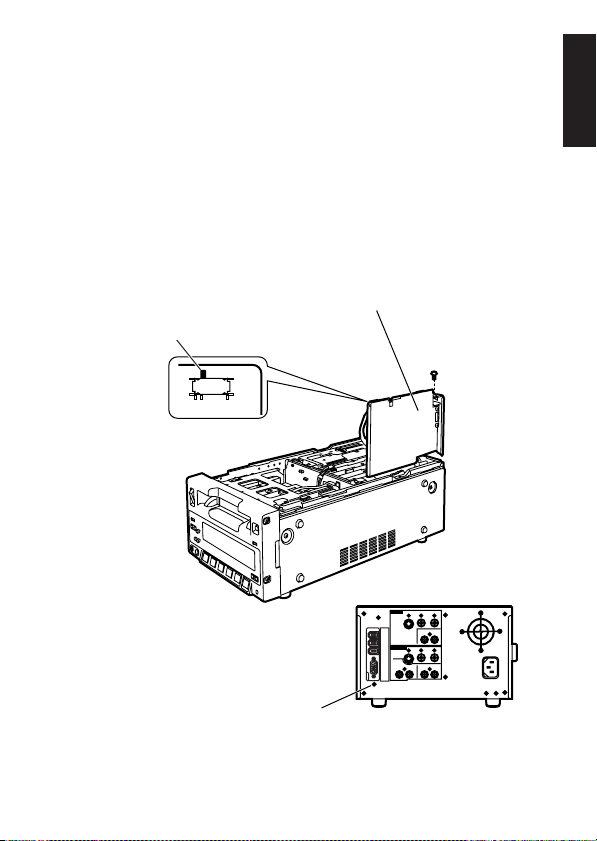
4.
Insert the AJ-YAD250P at the position previously
occupied by the RS-232C board, and use the mounting
screw to secure it in place.
<Notes>
O
Take care not to alter the position of the knob on
SW103 when inserting the interface board.
O
If it is difficult to insert the AJ-YAD250P, loosen screw
(A) on the rear panel then insert it again.
Be sure to tighten screw (A) after installing the AJYAD250P.
(A)
SW103
Mounting screw
AJ-YAD250P
Knob
(Face of the part)
E– 9
6.
Install the board clamp, and attach the top panel.
(Be absolutely sure to install the panel properly using the
screws provided.)
Board clamp
Top panel
5.
Connect the flat cable coming from the connector
(P1101) on the AV SYSCON board to the connector
(P101) on the AJ-YAD250P board.
P101
P1101
E– 10
ENGLISH
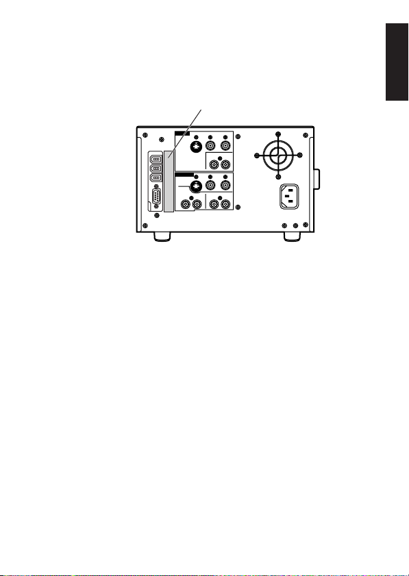
7.
Adhere the display label packed with the AJ-YAD250P
board to the AJ-D250’s rear panel.
Display label
E– 11
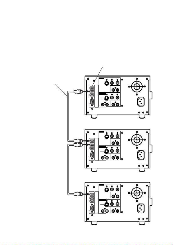
Equipment connections
Use a dedicated DVCPRO I/F cable (AJ-DTC2P or AJ-DTC4P)
to connect the AJ-D250.
(The input/output pins on the DVCPRO I/F connector are
bidirectional. No distinction is made between the input and
output sides.)
Dedicated DVCPRO I/F cable
(AJ-DTC2P or AJ-DTC4P)
DVCPRO I/F connector
AJ-D250
AJ-D250
AJ-D250

E– 12
ENGLISH
Equipment connections
<Notes>
O
Use a dedicated DVCPRO I/F cable (AJ-DTC2P or AJDTC4P) for the connection.
O
Avoid a loop connection since this will prevent the units from
operating properly.
O
The maximum number of AJ-D250 units which can be
connected is three.
O
The AV signals may be disturbed when the power of the
connected units is turned ON or OFF and when the I/F cable
is plugged in or disconnected.
O
It may take several seconds for the system operation to
stabilize when the input signals are selected or the mode is
changed. Wait until the system operation has stabilized
before proceeding to record.
O
If the analog video input signals are VHS or other nonstandard signals and ON has been selected as the setup
menu No.807 (DIF NSTD IN) setting, the sound and picture of
the receiving end device which has been connected using the
DVCPRO I/F connector may be disturbed or may not even be
output at all.
O
The volume recording level control on the front panel does
not function while recording with the DVCPRO I/F input is in
progress.
O
The capstan lock mode is fixed at the 2F mode when
recording using the DVCPRO I/F input. It will not be set to
the 4F mode even when the setup menu No.109 (CAP
LOCK) setting is changed.
E– 13
Equipment connections
<Notes>
O
Signal input for the consumer-use DV format is not
supported.
O
The DVCPRO I/F output will be in the DV format when a tape
in the consumer DV format or DVCAM format is played back
by the AJ-D250.
O
Use RS232C as the setup menu No.208 (REMOTE SEL)
setting when the AJ-D250 is to be controlled by the AJ-A250
(remote controller). (See page E-16)
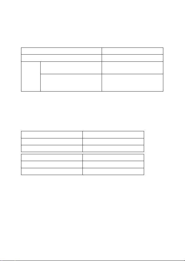
Input format Recording tape format
DVCPRO
DV,
DVCAM
DVCPRO
48kHz/16bit/2ch/
Locked audio signal
48kHz/16bit/2ch/
Signal other than locked
audio signal
DVCPRO
Recording not possible
i
i
i
Playback tape format Output format (DVCPRO)
DVCPRO DVCPRO
i
DV, DVCAM DV
i
Playback tape format Output format (DV)
DVCPRO DV
i
DV, DVCAM DV
i
The output format can be changed with the transmission side Setup
menu No. 801 (DIF TYPE) setting.(See page E-17)

E– 14
ENGLISH
Equipment connections
<Notes>
O
Insert editing using the DVCPRO I/F input is not possible
when the AJ-D250 is to be controlled as the recorder VTR by
the AJ-A250 (remote controller). (The RS-232C EIN
command and EAD command cannot be used when the
INPUT SELECT switch is at the OPTION position.)
Neither can the preview function be used during assemble
editing. When preview is attempted, the image near the IN
point is frozen and an error results. (The RS-232C IEV
command cannot be used when the INPUT SELECT switch is
at the OPTION position.)
When an error has occurred, it will be displayed on the
superimposed screen and on the front panel.
(See page E-29)
O
If the analog video input signals have been edited using AJA250 (remote controller) control, the video output picture may
be disturbed when an audio insert pause has been executed.
However, this will not have an adverse effect on what is
recorded on the unit's tape.
AJ-D250 settings
1.
When two or more AJ-D250 units are to be connected,
set the INPUT SELECT switch (front panel) of the AJD250 unit at the receiving end to the OPTION position.
2.
The set-up menus for the AJ-D250 units at both the
sending and receiving ends are now opened.
(Set the LOCAL/MENU/REMOTE switch on the front
panel to MENU.)
3.
Check that the set-up menu item No.803 (DIF OUT CH)
at the sending end and the set-up menu item No.802
(DIF IN CH) at the receiving end match. If they do not
match, adjust the channel settings.
E– 15
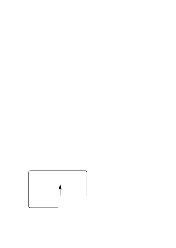
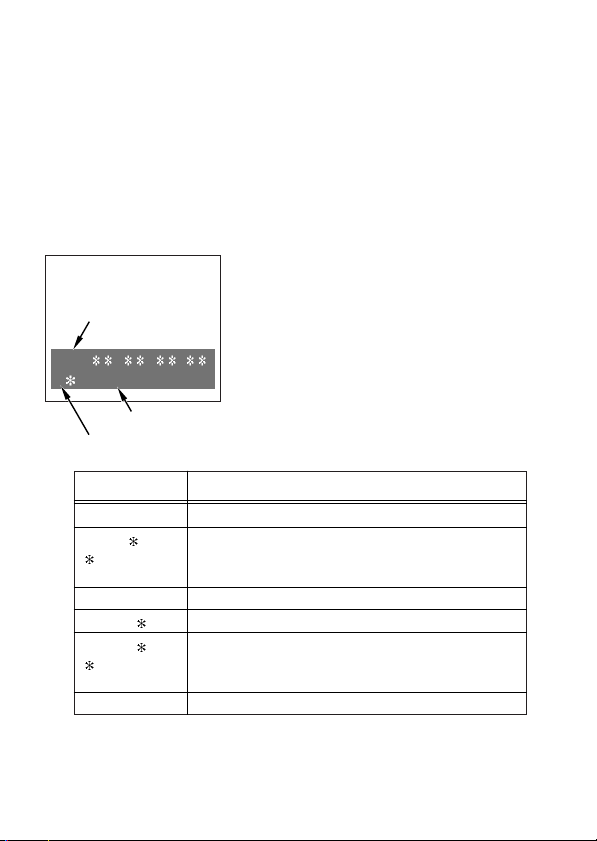
Superimposed display screen
The superimposed screen displayed on the TV monitor which is
connected to the MONITOR OUT connector will appear as
shown below if T&STA or T&S&R is used as the DISPLAY SEL
setup menu item setting.
Example of superimposed screen display with T&STA
setting
TCR
: : :
I STOP
TV monitor
VTR operating mode
Abbreviation (time code)
DVCPRO I/F status display
Display DVCPRO I/F status
I DVCPRO signal is received.
O DVCPRO signal is transmitted.
O
DV signal is transmitted.
No display Stop mode
O
( denotes
flashing)
Signal transmission mode is established but signals
cannot be transmitted.
I
( denotes
flashing)
Signal reception mode is established but packet is not
present or there is some other problem.
E– 16
ENGLISH
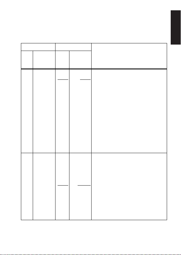
AJ-D250 set-up menus
The set-up menus change as follows once the interface board is
installed in the AJ-D250.
Item
Description of settings
208 This sets the external control.
0: Control is exercised by the
DVCPRO I/F AV/C command.
1: Control is exercised by the RS-232C
(9pin D-SUB) connector.
<Notes>
O
Menu item No.204 (ACK RETURN)
must be set to ON (0001) if control
is to be exercised by the 1394
settings.
O
A change made to the REMOTE
SEL setting will take effect only
when the power is turned off after
the setting has been changed and
then turned back on.
No.
Superimposed
display
Setting
No.
Superimposed
display
REMOTE
SEL 0000
0001
1394
RS232C
506 This sets the time code mode.
0: The time code generator is used in
the REC RUN mode.
1: The time code generator is used in
the FREE RUN mode.
2: The time code generator is used in
the internal regeneration mode.
3: When the INPUT SELECT switch is
at the LINE/S-VIDEO position, VITC
is selected; when it is at the
OPTION position, the DVCPRO I/F
time code input is selected.
TC MODE
0000
0001
0002
0003
P-REC
P-FREE
I-REG
EXT-TC
The underlined numbers and items are the factory settings.
E– 17
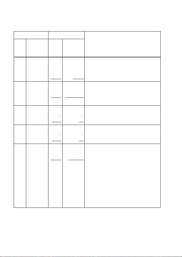
Item
Description of settings
800 This sets the DVCPRO I/F
transmission rate.
0: 100 Mbps
1: 200 Mbps
No.
Superimposed
display
Setting
No.
Superimposed
display
DIF
SPEED
0000
0001
S100
S200
802 This selects the DVCPRO I/F input
channel. (See page E-14)
DIF IN CH 0000
0063
0
63
803 This selects the DVCPRO I/F output
channel. (See page E-14)
DIF OUTCH0000
0063
0
63
805 This sets the mode when the input
data cannot be recorded.
0: The erase (all data erase) mode is
set.
1: Recording is stopped.
<Notes>
O
“E-02” is displayed on the front
panel while erase (all data erase)
mode is in progress.
O
Recording is not possible with
consumer-use DV signals.
DIF REC
SEL
0000
0001
ERASE
STOP
The underlined numbers and items are the factory settings.
AJ-D250 set-up menus
801 This sets the DVCPRO I/F
transmission format.
0: DVCPRO format
1: DV format
DIF TYPE
0000
0001
DVCPRO
DV
E– 18
ENGLISH
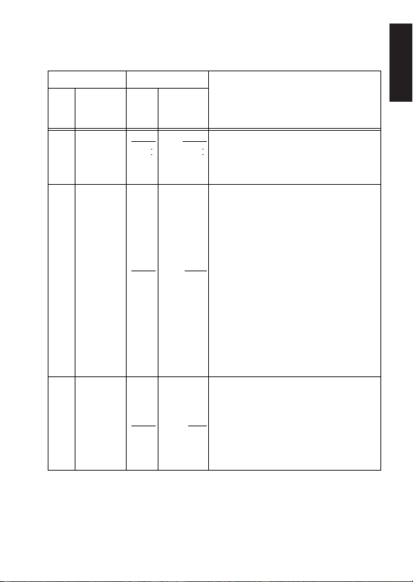
Item
Description of settings
806 This menu item is for an extended
system.
Normally, use the DFLT setting.
For details, consult your dealer.
No.
Superimposed
display
Setting
No.
Superimposed
display
DIF
CONFIG
0000
0255
DFLT
255
807 DIF NSTD
IN
0000
0001
OFF
ON
The underlined numbers and items are the factory settings.
AJ-D250 set-up menus
This sets whether signals are to be
output to DVCPRO I/F when the
analog input signals are non-standard
signals while the INPUT SELECT
switch is set to the LINE or S-VIDEO
position.
0: Non-standard signals are not output
to DVCPRO I/F.
<Note>
When INPUT SELECT switch is set
to the S-VIDEO position, even input
signals which are not non-standard
will not be output to DVCPRO I/F.
1: Input signals are output to DVCPRO
I/F.
808 This sets the audio input signals to be
selected when the INPUT SELECT
switch is set to the OPTION position.
0: This selects audio input signals from
DVCPRO I/F.
1: This selects audio input signals
(analog) other than DVCPRO I/F.
DIF AUD
SEL
0000
0001
DIF
ANA
 Loading...