

Panasonic aj-yac960 Operation Manual

SDTI Interface Board
AJ- P
Installation Guide
ENGLISH
DEUTSCHFRANÇAISITALIANOESPAÑOL
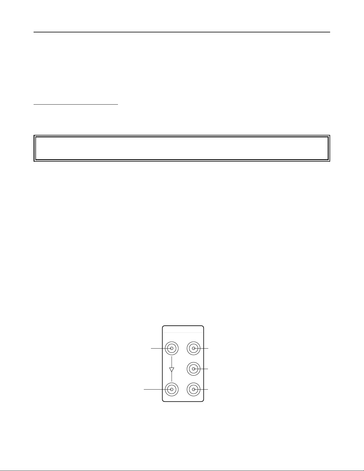
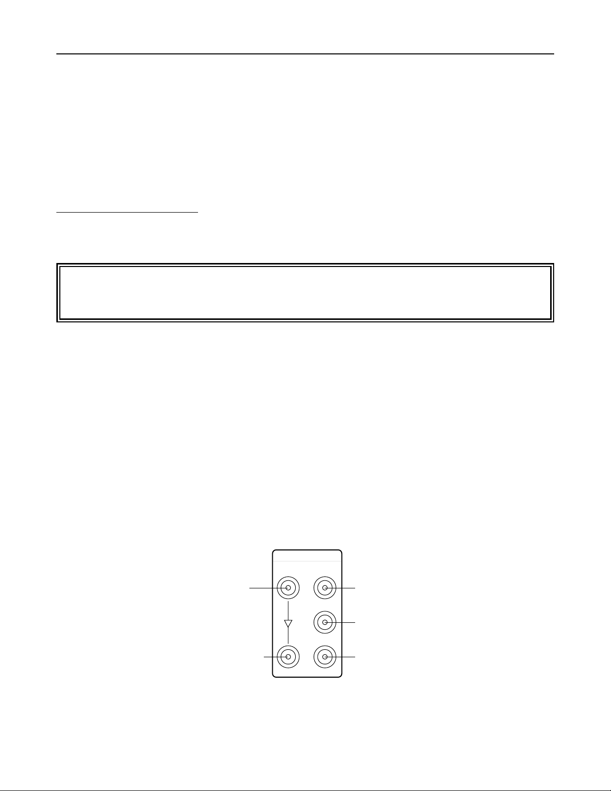
Connector area
Serial digital input connectors (BNC x 2)
1 Input : Used for both SDTI and SDI signals
2 Active through output
Serial digital output connectors (BNC x 3)
3 Output 1 : Used for both SDTI and SDI signals
4 Output 2 : Used exclusively for SDI signals
5 Output 3 : Used exclusively for SDI signals
E-1
1
2
3
SERIAL IN
SERIAL OUT
1 Input connector used for
both SDTI and SDI signals
2 Active through output
connector
4 Output connector used
exclusively for SDI signals
5 Output connector used
exclusively for SDI signals
3 Output connector used for
both SDTI and SDI signals
SDTI Interface Board
Introduction
AJ-YAC960P
The AJ-YAC960P is an SDTI interface board designed to be used with the AJ-D960. By installing it in the AJD960, digital data can be input and output using the SDTI format*1(compression digital interface).
*1: SDTI (serial data transport interface) complies with the SMPTE 305M standard.
The format of the data streams sent using the SDTI interface complies with the SMPTE 321M standard.
Refer the installation of the SDTI interface board to qualified service personnel. The VTR’s software may
need to be upgraded or its hardware changed.
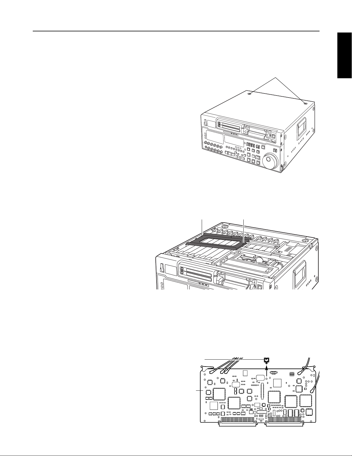
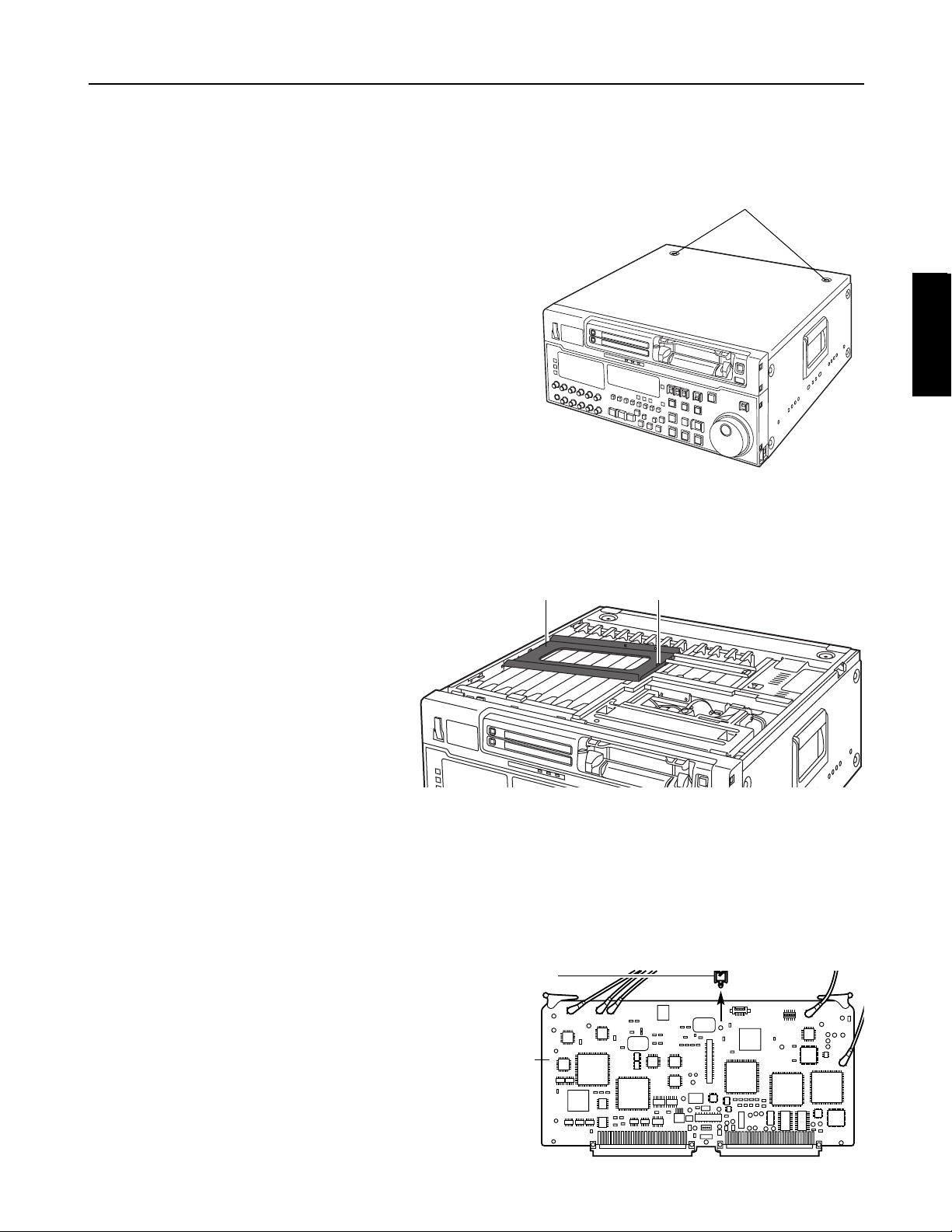
SDI board
Coin screws
Metal board clamp
Cable clamper
Check that the power of the VTR is off.
Remove the two coin screws, and take off the top panel
from the main unit.
1.
2.
E-2
Remove the screw, and remove the metal board clamp together with the screw. (This screw cannot be
removed from the clamp.)
3.
Detach the cable clamper which is attached to the SDI board.
4.
Remove the board (SDI board) inserted at the position marked “F4
”
on the main unit side.
(Do not disconnect the coaxial cables which are connected to the SDI board.)
5.
SDTI Interface Board
Installation
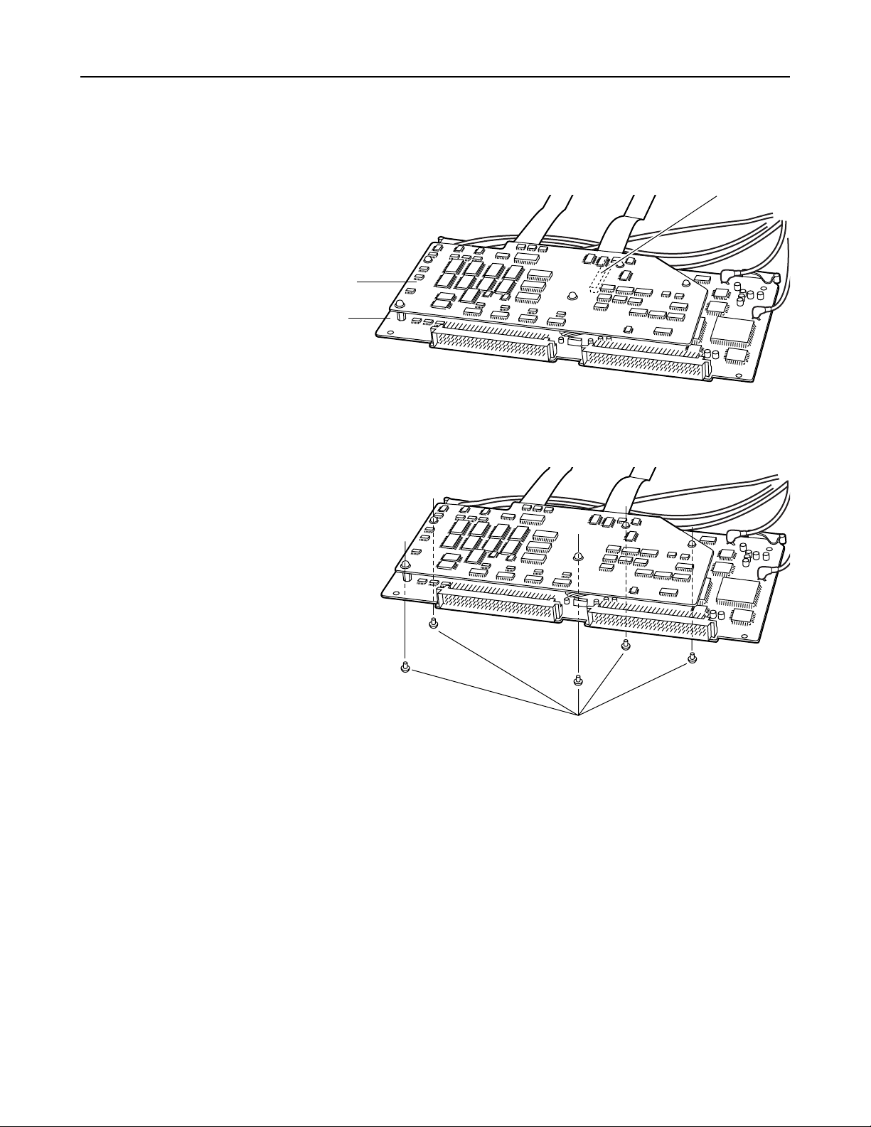
Screw
ENGLISH
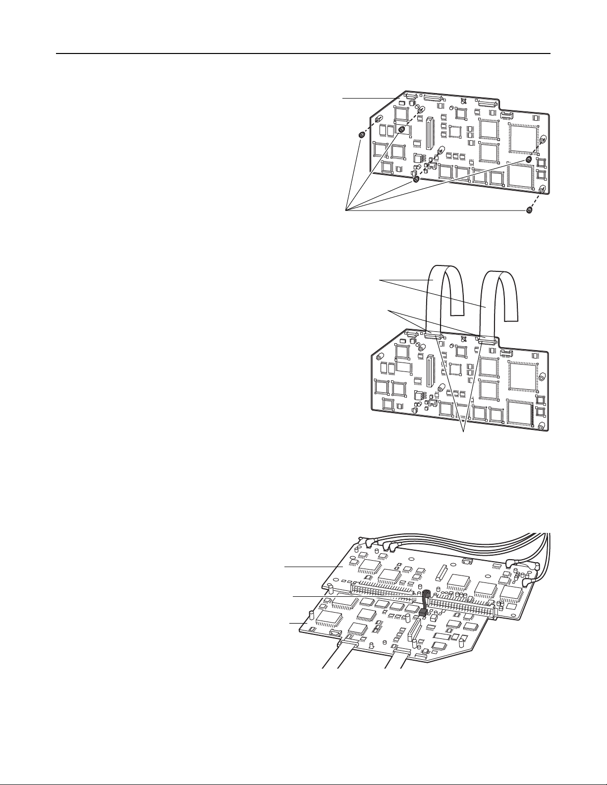
Remove the five screws attached to the
spacers on the SDTI board.
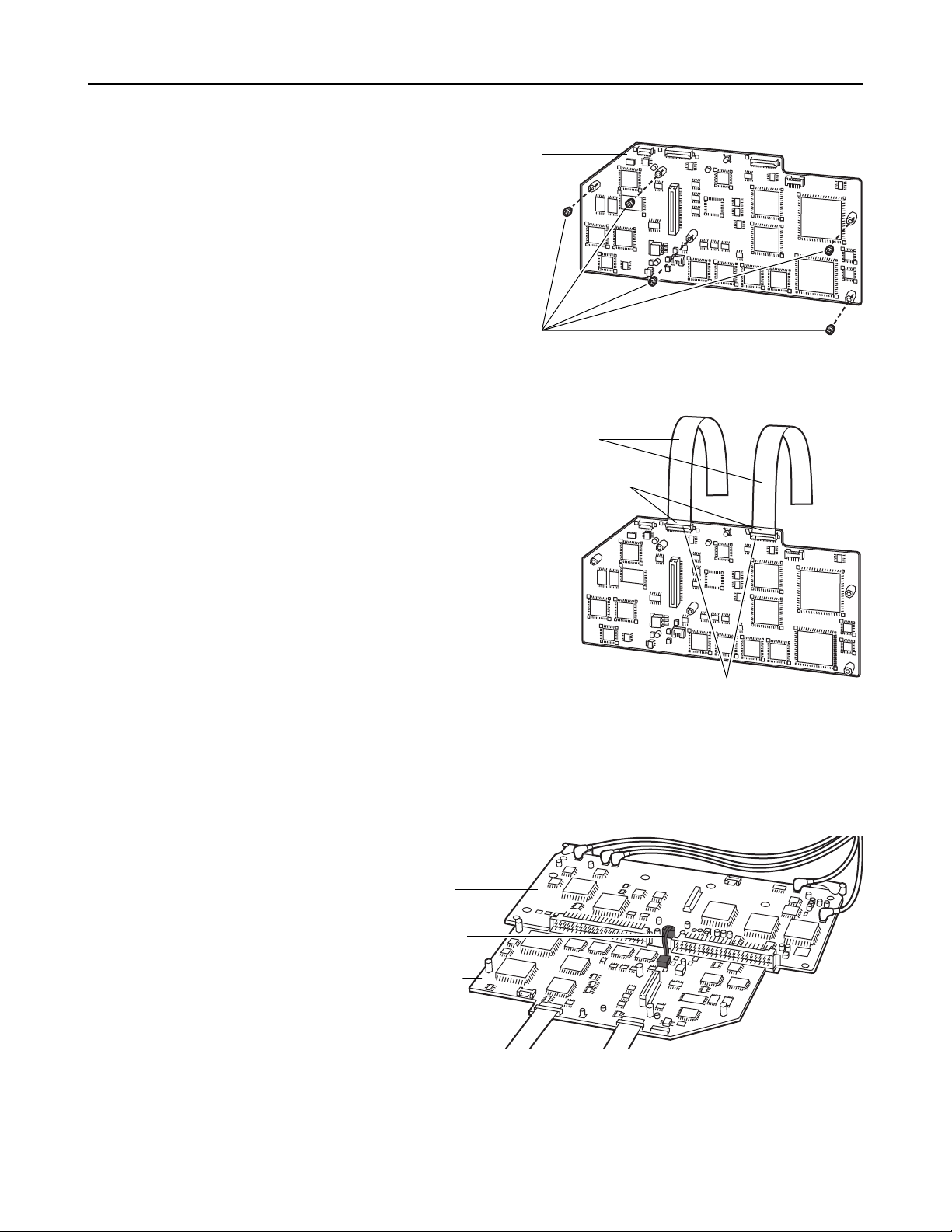
Attach the two flat cables supplied in the same
package as the SDTI board to the connectors on
the SDTI board.
Open the connector covers, insert the flat cables
so that the blue stickers are positioned on the top
surface, and then close the covers.
6.
7.
Attach the power cable attached to the SDTI board to the connector on the SDI board.
8.
E-3
SDTI Interface Board
Flat cables
Blue stickers
Covers
SDTI board
Screws (x5)
SDI board
Power cable
SDTI board
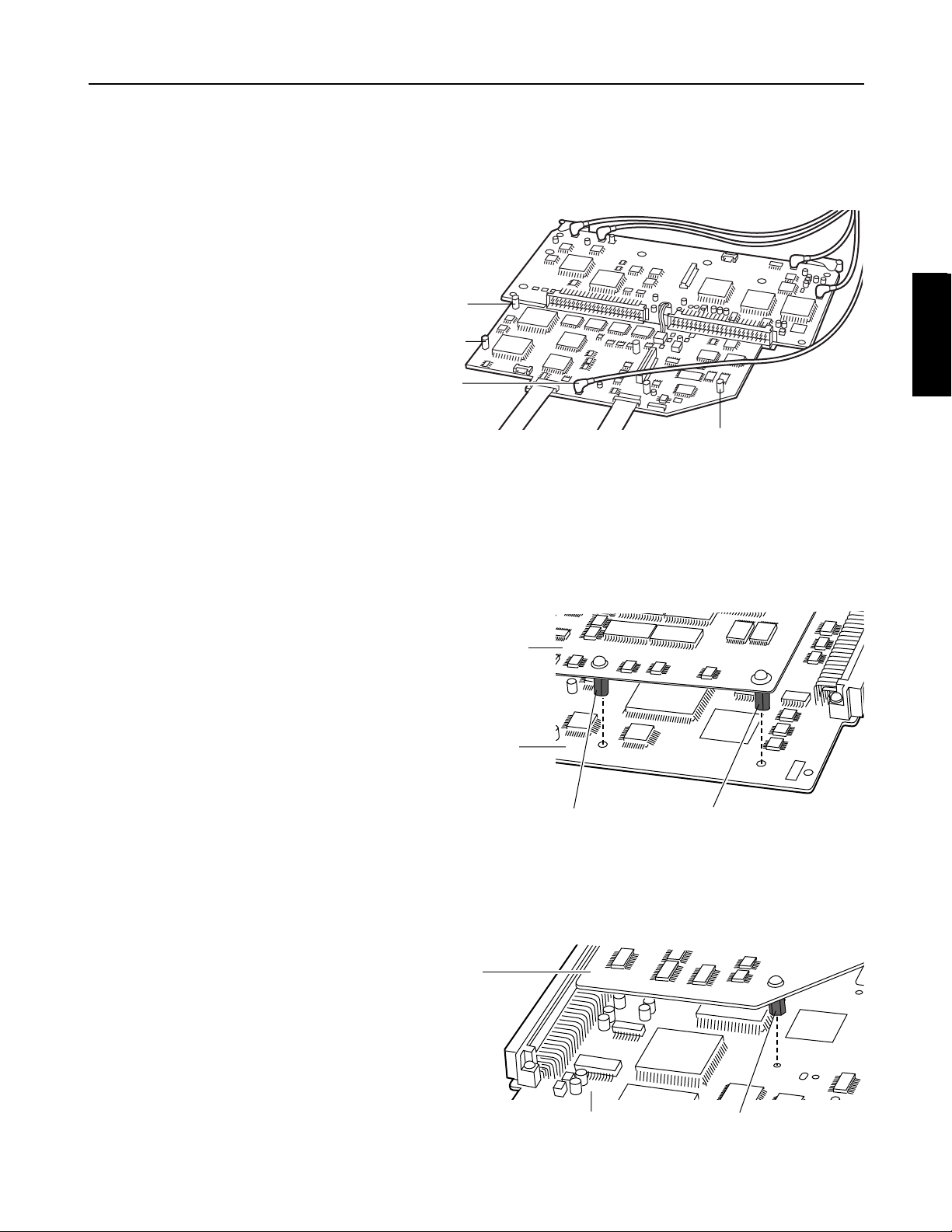
Disconnect the coaxial cable with the orange end from the SDI board, and connect it to the connector
located at the position on the SDTI board shown in the figure below.
Follow the steps below to attach the SDTI board to the SDI board.
1 Position spacer 1 and spacer 2 at the holes on the SDI board.
9
.
10.
E-4
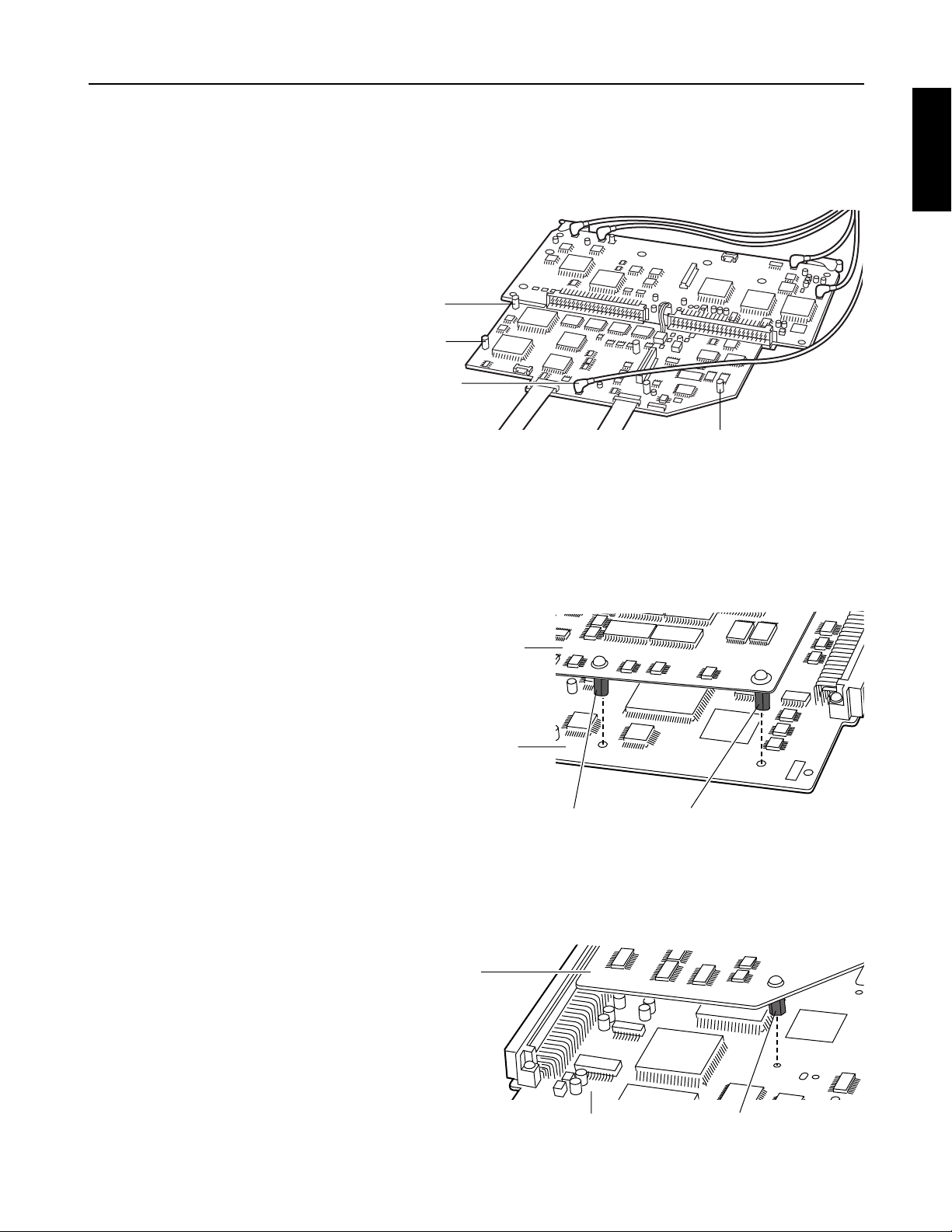
2 Position spacer 3 at the hole on the SDI board.
SDTI Interface Board
Orange end
of cable
Spacer 2
Spacer 1
Spacer 3
SDI board
SDTI board
Spacer 2Spacer 1
SDI board
SDTI board
Spacer 3
ENGLISH
E-
5
3 Attach the SDTI board to the SDI board in such a way that the connectors on the SDI board and
SDTI board are fitted precisely together.
4 Use the five screws removed in step 6 to attach the SDTI board to the SDI board.
<Notes>
≥ Wedge the excess length of the power cable between the SDTI board and SDI board.
≥ When installing the screws, take care not to drop them inside the VTR.
SDTI Interface Board
SDI board
SDTI board
Screws (x5)
Fit the connectors together here.

E-
6
SDTI Interface Board
Insert the SDI board at the position marked “F4” on the main unit side.
Following the same procedure as in step 7, attach the two flat cables to the connectors on the F5 board,
and wedge the excess lengths of these cables between the F5 and F6 boards.
12.
Insert the coaxial cables between the F4 and F5 boards.
13.
Install the metal board clamp using the screw for this purpose, and secure the top panel to the main unit
using the two coin screws.
14.
11.
F6 board
(F4) SDI and SDTI boards
F5 board
F6 board
(F4) SDI and SDTI boards
F5 board
Metal board clamp Screw
ENGLISH

E-7
Specifications
GENERAL
Weight: 170 g
Dimensions: 230 (W) x 113 (H) x 20 (D) mm
VIDEO INPUT
Serial digital input: BNC x 2
SERIAL IN: Used for both SDI/SDTI inputs
Active through output
SDI: Complies with SMPTE 259M-C standard
SDTI: Complies with SMPTE 305M/SMPTE 321M standards
VIDEO OUTPUT
Serial digital output: BNC x 3
SERIAL OUT 1: Used for both SDI/SDTI outputs
SERIAL OUT 2, 3: Used exclusively for SDI output (standard accessories)
SDI: Complies with SMPTE 259M-C standard
SDTI: Complies with SMPTE 305M/SMPTE 321M standards
AUDIO INPUT
Serial digital input: Complies with SMPTE 259M-C/SMPTE 272M-A standards
AUDIO OUTPUT
Serial digital output: Complies with SMPTE 259M-C/SMPTE 272M-A standards
* As with the video input/output, SDTI audio input/output complies with the SMPTE 305M/321M standards.
Weight and dimensions shown are approximate.
Specifications are subject to change without notice.
SDTI Interface Board

E-8
SDTI Interface Board
ENGLISH
Anschlussbereich
Serielle Digitaleingänge (BNC x 2)
1 Eingang : Wird für SDTI- und SDI-Signale verwendet
2 Aktiver Durchschaltungsausgang
Serielle Digitalausgänge (BNC x 3)
3 Ausgang 1 : Wird für SDTI- und SDI-Signale verwendet
4 Ausgang 2 : Wird ausschließlich für SDI-Signale verwendet
5 Ausgang 3 : Wird ausschließlich für SDI-Signale verwendet
D-1
1
2
3
SERIAL IN
SERIAL OUT
1 Eingang für SDTI- und
SDI-Signale
2 Aktiver
Durchschaltungsausgang
4 Ausgang nur für
SDI-Signale
5 Ausgang nur für
SDI-Signale
3 Ausgang für SDTI-
und SDI-Signale
SDTI-Schnittstellenkarte
Einleitung
AJ-YAC960P
Beim Modell AJ-YAC960P handelt es sich um eine SDTI-Schnittstellenkarte, die für den Einsatz mit dem AJD960 vorgesehen ist. Beim Modell AJ-YAC960P handelt es sich um eine SDTI-Schnittstellenkarte, die für den
Einsatz mit dem AJ-D960 vorgesehen ist.
Durch den Einbau der Karte in den AJ-D960 ist es möglich, digitale Daten im SDTI-Format*1ein- und
auszugeben (digitale Komprimierungs-Schnittstelle).
*1: SDTI (Serial Data Transport Interface) entspricht der Norm SMPTE 305M.
Das Format der durch die SDTI-Schnittstelle übertragenen Datenflüsse entspricht der Norm SMPTE 321M.
Überlassen Sie den Einbau der SDTI-Schnittstellenkarte qualifiziertem Wartungspersonal. Eine
Aktualisierung der Videorecorder-Software oder eine Änderung an seiner Hardware ist möglicherweise
notwendig.
SDI-Karte
Münzschrauben
Metallener Kartenhalter
Kabelklemme
Sicherstellen, dass die Stromversorgung des
Videorecorders ausgeschaltet ist.
Die zwei Münzschrauben herausdrehen, um die
Abdeckhaube von der Haupteinheit abzunehmen.
1.
2.
D-2
Die Schraube herausdrehen, und den metallenen Kartenhalter zusammen mit der Schraube entfernen.
(Diese Schraube kann nicht vom Halter entfernt werden.)
3.
Die an der SDI-Karte angebrachte Kabelklemme abnehmen.
4.
Die an der mit “F4” markierten Position in der Haupteinheit eingesetzte Karte (SDI-Karte) entfernen.
(Nicht die an die SDI-Karte angeschlossenen Koaxialkabel abtrennen.)
5.
SDTI-Schnittstellenkarte
Installation
Schraube
DEUTSCH
Die in den fünf Abstandshaltern der SDTI-Karte
sitzenden Schrauben herausdrehen.
Die in der Verpackung der SDTI-Karte enthaltenen
zwei Flachkabel an die Steckverbinder der SDTIKarte anschließen.
Die Anschlusskappen öffnen, die Flachkabel so
einführen, dass die blauen Aufkleber oben liegen,
und dann die Kappen schließen.
6.
7.
Das an der SDTI-Karte angebrachte Stromkabel an den Steckverbinder der SDI-Karte anschließen.
8.
D-3
SDTI-Schnittstellenkarte
Flachkabel
Blaue Aufkleber
Kappen
SDTI-Karte
Schrauben (x5)
SDI-Karte
Stromkabel
SDTI-Karte
Das Koaxialkabel mit dem orangefarbenen Ende von der SDI-Karte trennen und an den in der
nachstehenden Abbildung gekennzeichneten Steckverbinder der SDTI-Karte anschließen.
Die SDTI-Karte gemäß den unten beschriebenen Schritten an der SDI-Karte befestigen.
1 Die Abstandshalter 1 und 2 auf die Löcher in der SDI-Karte ausrichten.
9.
10.
D-4
2 Den Abstandshalter 3 auf das Loch in der SDI-Karte ausrichten.
SDTI-Schnittstellenkarte
Orangefarbenes
Kabelende
Abstandshalter 2
Abstandshalter 1
Abstandshalter 3
SDI-Karte
SDTI-Karte
Abstandshalter 2Abstandshalter 1
SDI-Karte
SDTI-Karte
Abstandshalter 3
DEUTSCH
 Loading...