


Panasonic aj-ya901 Operation Manual

SDI output Board
AJ-
Installation Guide
P
E
EN
ENGLISH
DEUTSCH
FRANÇAIS
ITALIANO
ESPAÑOL
E - 1
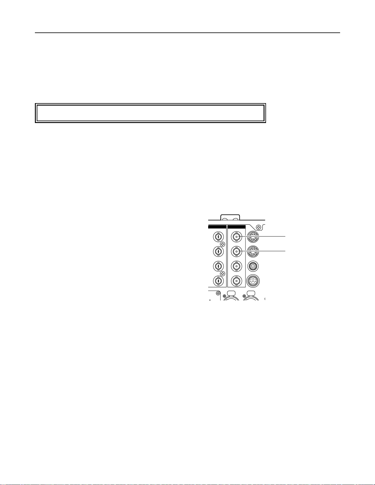
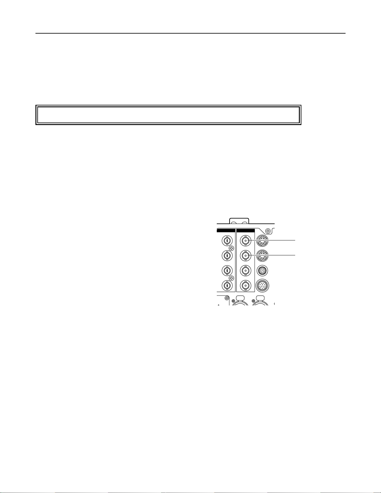
Connector Area (AJ-BS900)
Serial digital output connectors (BNC x2)
1 Output 1: SDI output
2 Output 2: SDI output
Y
2
SDI output
1 SDI output
Overview
AJ-YA901P/E
This SDI output board is designed for use with the AJ-BS900. Its installation in the AJ-BS900 enables digital data output
using the SDI format.
Overview/Connector Area
Refer the installation of the SDI output board to qualified service personnel.
Y/G
B/B
R/R
FM
ATION
PUSH
SDI OUTOUT
4:2:2
OP3
4:2:2
OP1
OP2
AUDIO
OUT
CH 1
PUSH
OP4
WFM
TALL
CH 2

E - 2
ENGLISH
EXT DC IN
GEN–
LOCK
ENC
1
ENC
2
ENC
3
PIX
Y/G
4:2:2
4:2:2
SDI OUTOUTIN
OP4
OP3
WFM
TALLY
FUSE
SIGNAL
GND
AC IN
AUDIO
OUT
CH 1
PUSH
CH 2
PUSH
COMMUNICATION
PB/B
PR/R
WFM
RET 1
RET 2
PROMPT
OP1
OP2
1.
2.
3.
4.
Installation
C
A
B
LE
S
H
O
R
T
A
L
A
R
M
F
U
S
E
H
E
A
D
P
O
W
E
R
O
N
O
F
F
M
A
I
N
O
N
O
F
F
F
U
S
E
O
P
E
N
D
I
G
IT
A
L
T
R
IA
X
G
E
N
L
O
C
K
O
F
F
S
C
H
C
O
A
R
S
E
INTE
RCOM
P
G
M
O
N
O
F
F
P
T
T
M
I
C
P
R
I
V
A
T
E
S
Y
S
T
E
M
P
U
S
H
P
H
A
S
E
V
TR
E
N
A
B
L
E
REW
FF
STOP
S
H
U
T
T
E
R
S
E
T
U
P
M
O
N
S
E
L
K
N
E
E
P
O
I
N
T
K
N
E
E
S
L
O
P
E
G
A
M
M
A
D
E
T
A
I
L
M
.PE
D
O
N
O
FF
(PUSH)
R
G
E
N
G
S
E
Q
B
S
U
P
S
.V
S
.S
1
0
0
(
6
0
)
1
0
0
0
1
2
0
2
5
0
5
0
0
2
0
0
0
W
H
IT
E
B
A
L
PLA
Y
A
W
B
C
H
E
C
K
A
U
T
O
I
R
I
S
I
R
I
S
B
R
G
A
I
N
FILTER
A
B
B
B
A
R
E
N
A
B
L
E
P
A
I
N
T
IN
G
G
A
I
N
A
U
T
O
K
N
E
E
G
A
I
N
R
E
C
C
H
K
S
T
AR
T
/ S
T
O
P
CA
LL
T
A
L
L
Y
VTR W
ARNING
PRE
A
B
B
L
A
C
K
B
a
s
e
S
ta
t
i
o
n
A
J
-
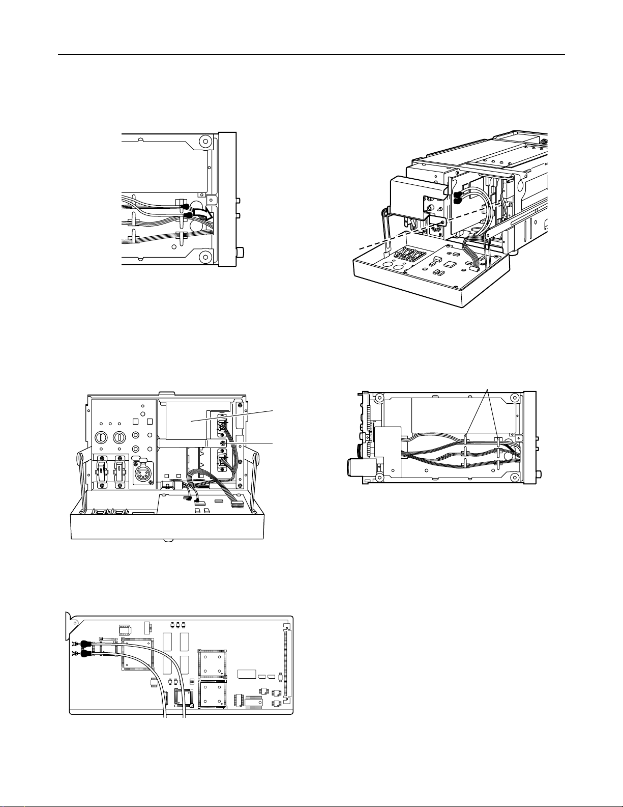
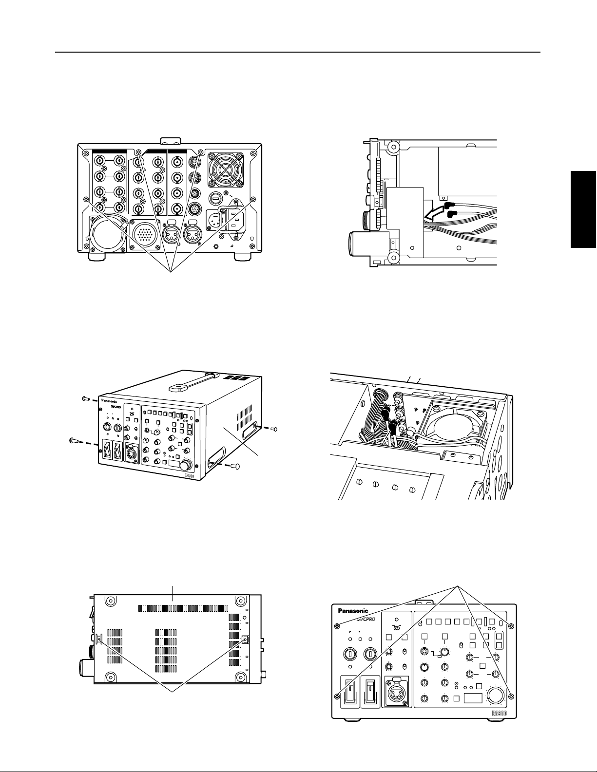
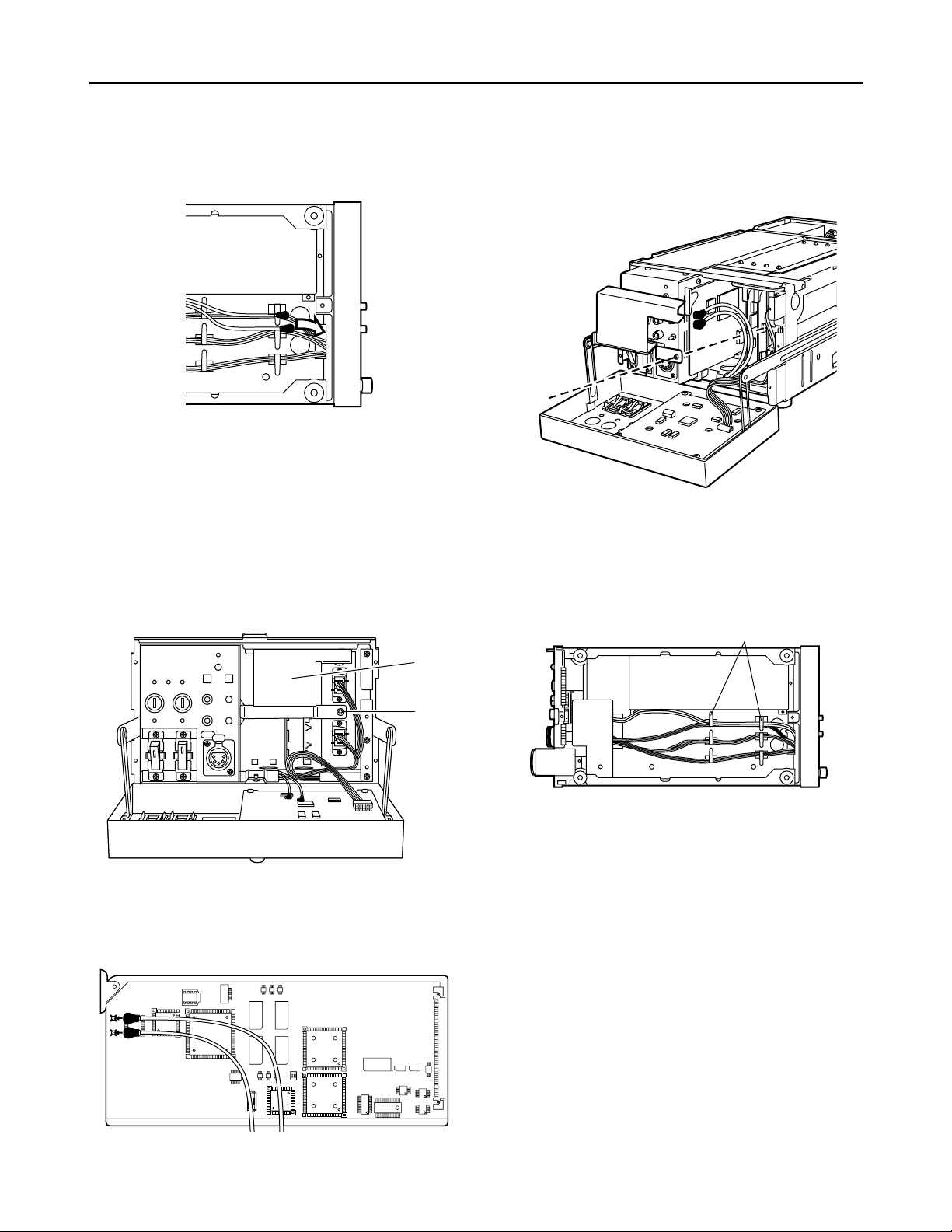
Follow the steps below to install the AJ-YA901 (referred to below as “the board”) in the AJ-BS900.
Refer to the figure below, and remove the four screws
from the rear panel of the AJ-BS900.
Remove the two screws each from the left and right
side panels of the AJ-BS900 to remove the side
panels.
Remove the two screws from the bottom panel of the
AJ-BS900 to remove the bottom panel.
6.
Remove the four screws on the front panel of the AJBS900, and pull off the front panel cover. (The screws
cannot be removed from the front panel cover.)
Pass the ends of the cables attached to the board from
the position at the bottom shown in the figure below
toward the top of the rear panel.
Screws (x4)
Screws (x2)
Screws (x4)
Side panel
Bottom panel
5.
Connect the cables, which were inserted into the AJBS900 in step 4, on the inner side of the SDI output
connectors. For details on the positions of these
connectors, refer to the figure below and to “Connector
Area” (page E-1).
CABLE
SHORT ALARM
FUSE
GENLOCK
VTR
ENABLE
WHITE
BAL
REW
Base Station AJ-
FF STOP
SHUTTERSET UP
MON SEL
KNEE
POINT
KNEE
SLOPE
GAMMA
DETAIL
M.PED
PLAY
AWB
CHECK
AUTO IRIS
IRIS
BR
GAIN
FILTER
ABB
BAR
ENABLE
PAINTING
GAIN
AUTO KNEE
GAIN
REC CHK
START / STOP
CALL
TALLY
VTR WARNING
ON
OFF
(PUSH)
OFFSC H
COARSE
INTERCOM
PGM
ON
OFF
PTT
PRE
A
B
MIC
PRIVATE
SYSTEM
PUSH
PHASE
HEAD POWER
ON
OFF
MAIN
ON
OFF
FUSE
OPEN
BLACK
RGENG
SEQ
B SUP
S.V
S.S.
100(60)
1000
120
250
500
2000
DIGITAL TRIAX
E - 3
Installation
PUSH
P
U
S
H
PUSH
7.
10
.
While referring to the figure below, pass the other ends
of the cables connected in step 5 from the bottom
toward the front panel top.
8.
Remove the screw from the front panel of the cover
removed from the AJ-BS900, and disengage the metal
piece shown in the figure below. (The screw cannot be
removed from the metal piece.)
9.
Connect the ends of the cables which were passed
from the bottom in step 7 to the board so that they are
aligned in the directions shown in the figure below.
Insert the board into the left-most slot of the AJ-BS900,
and reattach the metal piece, which was disengaged in
step 8, to its original position. When securing the metal
piece, ensure that the cables are not pinched.
Screw
Metal piece
11
.
Pull out the excess lengths of the cables toward the
bottom, and anchor the cables using cable clamps so
that no slack remains in the cables.
12
.
Return the front panel cover, bottom panel and side
panels in this order to their original positions, and
secure them using the respective screws.
Cable clamps

E - 4
ENGLISH
Specifications
GENERAL
Weight: 170 g
Dimensions: 230 (W) x 113 (H) x 20 (D) mm
VIDEO OUTPUT
Serial digital output connectors: BNC x 2
SERIAL OUT 1: SDI output connector
SERIAL OUT 2: SDI output connector
SDI: Compliant with SMPTE 259M-C standard
AUDIO OUTPUT
Serial digital output connectors: Compliant with SMPTE 259M-C/SMPTE 272M-A standards
Specifications
D - 1
Anschlussbereich (AJ-BS900)
Serielle Digitalausgänge (BNC x 2)
1 Ausgang 1: SDI-Ausgang
2 Ausgang 2: SDI-Ausgang
Y
2
SDI-Ausgang
1
SDI-Ausgang
Übersicht/Anschlussbereich
Übersicht
AJ-YA901P/E
Diese SDI-Ausgangsplatine ist für den Einsatz mit dem AJ-BS900 vorgesehen. Ihr Einbau in den AJ-BS900 ermöglicht die
digitale Datenausgabe im SDI-Format.
Überlassen Sie den Einbau der SDI-Ausgangsplatine qualifiziertem Wartungspersonal.
Y/G
B/B
R/R
FM
ATION
SDI OUTOUT
PUSH
4:2:2
4:2:2
OP1
OP2
AUDIO
OUT
CH 1
PUSH
OP3
OP4
WFM
TALL
CH 2
D - 2
DEUTSCH
EXT DC IN
GEN–
LOCK
ENC
1
ENC
2
ENC
3
PIX
Y/G
4:2:2
4:2:2
SDI OUTOUTIN
OP4
OP3
WFM
TALLY
FUSE
SIGNAL
GND
AC IN
AUDIO
OUT
CH 1
PUSH
CH 2
PUSH
COMMUNICATION
PB/B
PR/R
WFM
RET 1
RET 2
PROMPT
OP1
OP2
1.
2.
3.
4.
Installation
C
A
B
LE
S
H
O
R
T
A
L
A
R
M
F
U
S
E
H
E
A
D
P
O
W
E
R
O
N
O
F
F
M
A
I
N
O
N
O
F
F
F
U
S
E
O
P
E
N
D
I
G
IT
A
L
T
R
IA
X
G
E
N
L
O
C
K
O
F
F
S
C
H
C
O
A
R
S
E
INTE
RCOM
P
G
M
O
N
O
F
F
P
T
T
M
I
C
P
R
I
V
A
T
E
S
Y
S
T
E
M
P
U
S
H
P
H
A
S
E
V
TR
E
N
A
B
L
E
REW
FF
STOP
S
H
U
T
T
E
R
S
E
T
U
P
M
O
N
S
E
L
K
N
E
E
P
O
I
N
T
K
N
E
E
S
L
O
P
E
G
A
M
M
A
D
E
T
A
I
L
M
.PE
D
O
N
O
FF
(PUSH)
R
G
E
N
G
S
E
Q
B
S
U
P
S
.V
S
.S
1
0
0
(
6
0
)
1
0
0
0
1
2
0
2
5
0
5
0
0
2
0
0
0
W
H
IT
E
B
A
L
PLA
Y
A
W
B
C
H
E
C
K
A
U
T
O
I
R
I
S
I
R
I
S
B
R
G
A
I
N
FILTER
A
B
B
B
A
R
E
N
A
B
L
E
P
A
I
N
T
IN
G
G
A
I
N
A
U
T
O
K
N
E
E
G
A
I
N
R
E
C
C
H
K
S
T
AR
T
/ S
T
O
P
CA
LL
T
A
L
L
Y
VTR W
ARNING
PRE
A
B
B
L
A
C
K
B
a
s
e
S
ta
t
i
o
n
A
J
-
Führen Sie die folgenden Schritte aus, um die Platine AJ-YA901 in den AJ-BS900 einzubauen.
Die in der nachstehenden Abbildung gezeigten vier
Schrauben von der Rückwand des AJ-BS900
entfernen.
Je zwei Schrauben von der linken und rechten
Seitenwand des AJ-BS900 entfernen, und die
Seitenwände abnehmen.
Zwei Schrauben von der Bodenplatte des AJ-BS900
entfernen, und die Bodenplatte abnehmen.
6.
Die vier Schrauben von der Frontplatte des AJ-BS900
entfernen, und die Frontplattenabdeckung abziehen.
(Die Schrauben können nicht von der
Frontplattenabdeckung entfernt werden.)
Die Enden der an der Platine angebrachten Kabel von
der in der folgenden Abbildung gezeigten Position an
der Unterseite zur Oberseite der Rückwand führen.
Schrauben (x 4)
Schrauben (x 2)
Schrauben (x 4)
Seitenwand
Bodenplatte
5.
Die in Schritt 4 in den AJ-BS900 eingeführten Kabel an
der Innenseite der SDI-Ausgangsbuchsen anschließen.
Einzelheiten zur Lage dieser Buchsen sind der
folgenden Abbildung und dem Abschnitt
“Anschlussbereich” (Seite D-1) zu entnehmen.
CABLE
SHORT ALARM
FUSE
GENLOCK
VTR
ENABLE
WHITE
BAL
REW
Base Station AJ-
FF STOP
SHUTTERSET UP
MON SEL
KNEE
POINT
KNEE
SLOPE
GAMMA
DETAIL
M.PED
PLAY
AWB
CHECK
AUTO IRIS
IRIS
BR
GAIN
FILTER
ABB
BAR
ENABLE
PAINTING
GAIN
AUTO KNEE
GAIN
REC CHK
START / STOP
CALL
TALLY
VTR WARNING
ON
OFF
(PUSH)
OFFSC H
COARSE
INTERCOM
PGM
ON
OFF
PTT
PRE
A
B
MIC
PRIVATE
SYSTEM
PUSH
PHASE
HEAD POWER
ON
OFF
MAIN
ON
OFF
FUSE
OPEN
BLACK
RGENG
SEQ
B SUP
S.V
S.S.
100(60)
1000
120
250
500
2000
DIGITAL TRIAX
D - 3
Installation
PUSH
P
U
S
H
PUSH
7.
10
.
Die anderen Enden der in Schritt 5 angeschlossenen
Kabel gemäß der folgenden Abbildung von der
Unterseite zur Oberseite der Frontplatte führen.
8.
Die markierte Schraube von der freigelegten
Vorderseite des AJ-BS900 entfernen, und die in der
folgenden Abbildung gezeigte Metallplatte abnehmen.
(Die Schraube kann nicht von der Metallplatte entfernt
werden.)
9.
Die Enden der in Schritt 7 von der Unterseite
eingeführten Kabel so an die Platine anschließen, dass
die Kabel gemäß der folgenden Abbildung verlaufen.
Die Platine in den äußersten linken Steckplatz des AJBS900 einführen, und die in Schritt 8 abgenommene
Metallplatte wieder an ihrem ursprünglichen Platz
anbringen. Beim Befestigen der Metallplatte darauf
achten, dass die Kabel nicht eingeklemmt werden.
Schraube
Metallplatte
11
.
Die überschüssigen Kabellängen nach unten ziehen,
und die Kabel mit den Kabelklemmen so verankern,
dass sie keinen Durchhang haben.
12
.
Frontplattenabdeckung, Bodenplatte und Seitenwände
in dieser Reihenfolge wieder anbringen und mit den
jeweiligen Schrauben befestigen.
Kabelklemmen