

Panasonic aj-ya455 Operation Manual

AJ- P
Component Serial Interface Board
Operating Instructions
ENGLISH
DEUTSCH
FRANÇAIS
ITALIANO
ESPAÑOL
1(E)
Component Serial Interface Board
Contents
Precautions . . . . . . . . . . . . . . . . . . . . . . . . . . . . . . . . . . . .
1
Features . . . . . . . . . . . . . . . . . . . . . . . . . . . . . . . . . . . . . . .
1
Installation . . . . . . . . . . . . . . . . . . . . . . . . . . . . . . . . . . . . .
2
Specifications . . . . . . . . . . . . . . . . . . . . . . . . . . . . . . . . . . .
5
Precautions
O
Do not touch this product with wet hands.
O
Do not drop this product or subject it to other strong
shock.
O
Do not attempt to modify this product. Doing so may
cause it to malfunction.
Features
This product is a component serial interface board designed
to be used exclusively with the AJ-D455P digital VTR.
The installation of this interface board enables the input and
output of digital signals.
1(E)
CAUTION:
TO REDUCE THE RISK OF FIRE OR SHOCK
HAZARD, REFER MOUNTING OF THE
OPTIONAL INTERFACE BOARD TO
AUTHORIZED SERVICE PERSONNEL.
indicates safety information.
2(E)
ENGLISH
Installation
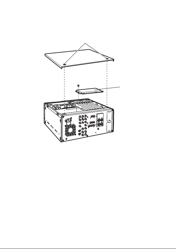
1.
Check that the power to the AJ-D455 is OFF.
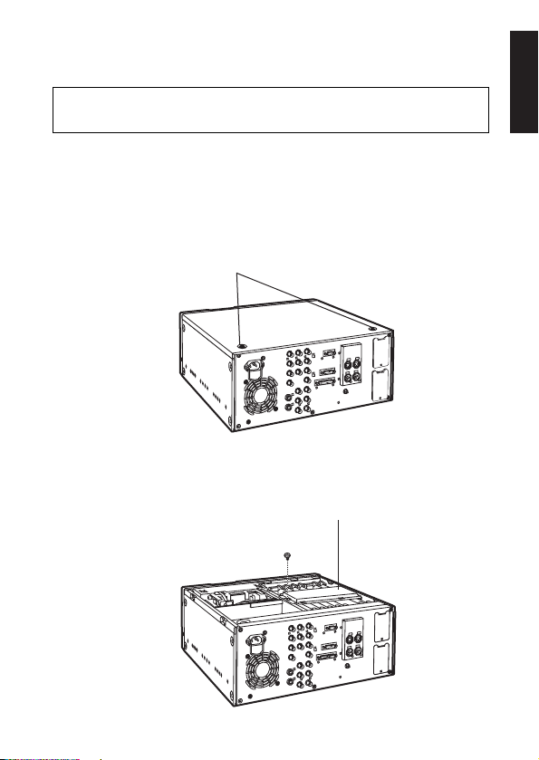
2.
Remove the 2 coin screws and top panel from the unit.
Consult your dealer for details on installing this
interface board.
Coin screws
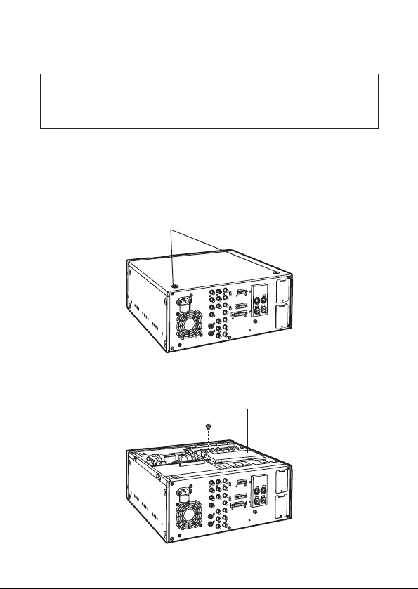
3.
Remove the screw and board clamp.
Screw
Board clamp
3(E)
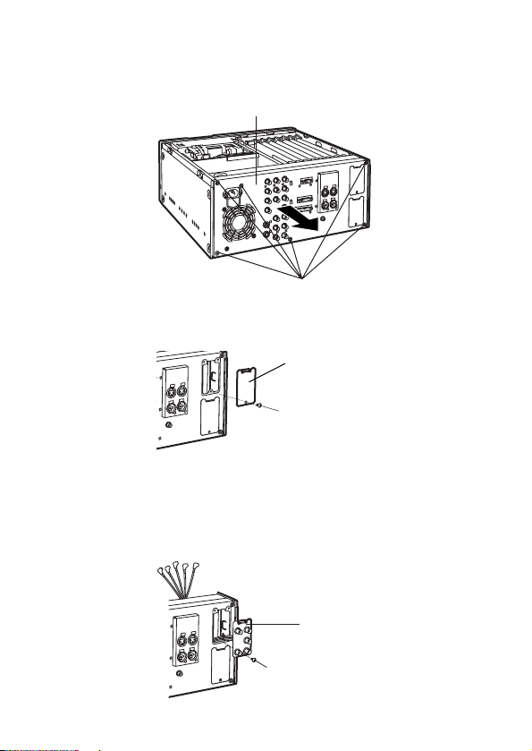
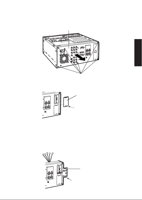
6.
Attach the accessory connector board to the rear panel.
Pass the wiring through the rear panel, attach the top
side of the connector board and secure the lower side
of the board in place with the screw, as shown in the
diagram below.
5.
Remove the screw and remove the blank panel from the
rear panel.
Screw
Screw
Accessory connector
board
Blank panel
3(E)
4.
Remove the 6 screws and pull the rear panel directly
backwards to remove.
Rear panel
Screws
4(E)
ENGLISH
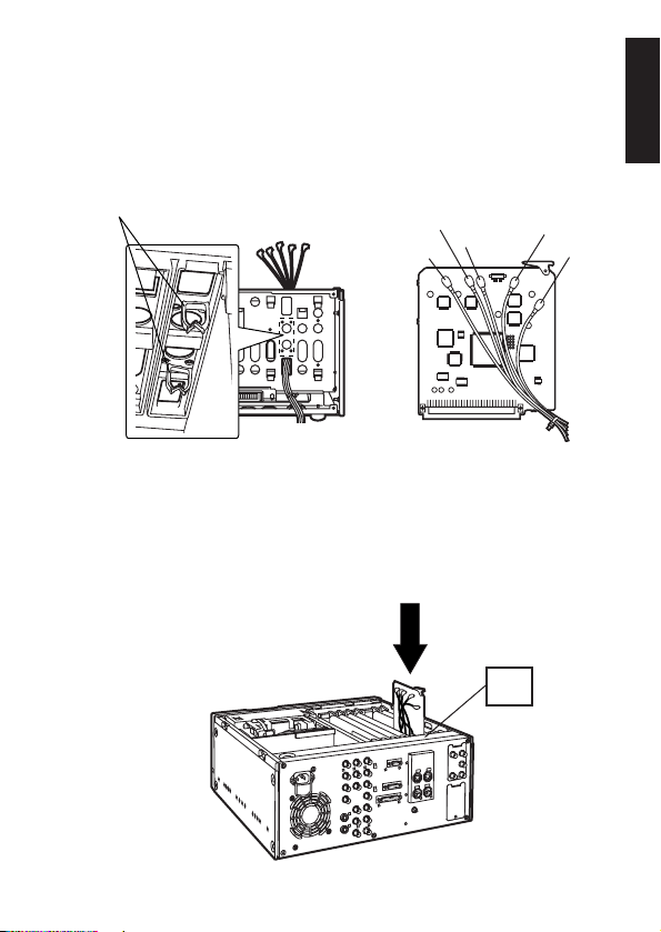
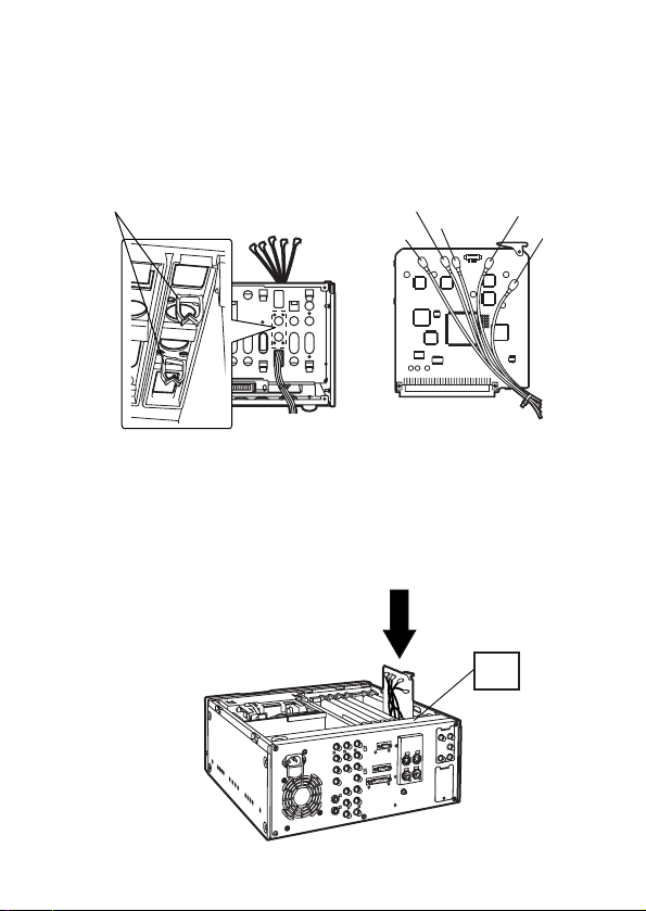
7.
Pass the wiring through the unit and secure the rear
panel with the 6 screws. Ensure that the wiring and
connections are as shown in the respective diagrams
below.
Wiring Diagram
Connections Diagram
F3
8.
Insert the board into the rear panel side of the slot
marked F3.
Green
Yellow
Orange
Black
Red
Clampers
View from rear
5(E)
9.
Attach the board clamp with the screw and secure the
top panel to the unit with the 2 coin screws.
Video input:
BNC t2, active through
Video output:
BNC t3
Weight:
0.21 lb. (94 g) (board),
0.2 lb. (90 g) (connector board)
Dimensions (WtH):
5˝t5-1/2˝ (127t140 mm) (board),
1-5/8˝t2-3/4˝ (42t71 mm) (connector board)
Specifications
Coin Screws
Screw
Board Clamp

1(G)
DEUTSCH
Inhalt
Vorsichtsmaßnahmen . . . . . . . . . . . . . . . . . . . . . . . . . . . .
1
Merkmale . . . . . . . . . . . . . . . . . . . . . . . . . . . . . . . . . . . . . .
1
Installation . . . . . . . . . . . . . . . . . . . . . . . . . . . . . . . . . . . . .
2
Technische Daten . . . . . . . . . . . . . . . . . . . . . . . . . . . . . . .
5
Vorsichtsmaßnahmen
O
Berühren Sie dieses Produkt nicht mit nassen Händen.
O
Lassen Sie dieses Produkt nicht fallen, und setzen Sie es
auch sonst keinen starken Erschütterungen aus.
O
Versuchen Sie nicht, dieses Produkt zu modifizieren.
Anderenfalls kann es zu Funktionsstörungen kommen.
Merkmale
Diese serielle Komponenten-Schnittstellenkarte ist speziell
für den Einsatz mit dem digitalen Videorecorder AJ-D455P
vorgesehen.
Der Einbau dieser Schnittstellenkarte ermöglicht die Einund Ausgabe von digitalen Signalen.
Serielle Komponenten-Schnittstellenkarte
VORSICHT:
UM BRAND- ODER STROMSCHLAGGEFAHR
ZU REDUZIEREN, ÜBERLASSEN SIE DEN
EINBAU DER GESONDERTEN
SCHNITTSTELLENKARTE QUALIFIZIERTEM
WARTUNGSPERSONAL.
ist die Sicherheitsinformation.
2(G)
Installation
1.
Vergewissern Sie sich, dass die Stromversorgung des
AJ-D455 ausgeschaltet ist.
2.
Die 2 Münzschrauben herausdrehen, um die
Abdeckhaube von der Haupteinheit abzunehmen.
Bitte wenden Sie sich bezüglich weiterer
Einzelheiten zum Einbau dieser Schnittstellenkarte
an Ihren Händler.
Münzschrauben
3.
Die Schraube herausdrehen, und den Kartenhalter
abnehmen.
Schraube
Kartenhalter
3(G)
DEUTSCH
6.
Die mitgelieferte Anschlusskarte an der Rückwand
anbringen.
Die Kabel durch die Rückwand führen, die Oberseite
der Anschlusskarte anbringen, und die Unterseite der
Karte mit der Schraube befestigen, wie in der
nachstehenden Abbildung gezeigt.
5.
Die Schraube entfernen, und die Blindplatte von der
Rückwand abnehmen.
Schraube
Schrauben
Mitgelieferte
Anschlusskarte
Blindplatte
4.
Die 6 Schrauben herausdrehen, und die Rückwand zum
Abnehmen gerade nach hinten ziehen.
Rückwand
Schrauben
4(G)
7.
Die Kabel durch die Einheit führen, und die Rückwand
mit den 6 Schrauben befestigen. Sicherstellen, dass die
Verkabelung und die Anschlüsse dem jeweiligen
Schaltplan entsprechen.
Schaltplan
Anschlussdiagramm
F3
8.
Die Karte in den mit F3 markierten Steckplatz auf der
Rückwandseite einführen.
Grün
Gelb
Orange
Schwarz
Rot
Klemmen
Rückansicht
 Loading...