

Panasonic AJ-HPX3000G Operating Instructions

Operating Instructions
Memory Card Camera-Recorder
Model No. AJ-HPX3000G
Before operating this product, please read the insructions carefully and save this manual for future use.
F0807T0 -F @
Printed in Japan
ENGLISH
VQT1K82
Read this first!
CAUTION
RISK OF ELECTRIC SHOCK
DO NOT OPEN
CAUTION: TO REDUCE THE RISK OF ELECTRIC SHOCK,
REFER TO SERVICING TO QUALIFIED SERVICE PERSONNEL.
DO NOT REMOVE COVER (OR BACK).
NO USER SERVICEABLE PARTS INSIDE.
The lightning flash with arrowhead symbol,
within an equilateral triangle, is intended to
alert the user to the presence of uninsulated
“dangerous voltage” within the product’s
enclosure that may be of sufficient magnitude
to constitute a risk of electric shock to persons.
The exclamation point within an equilateral
triangle is intended to alert the user to the
presence of important operating and
maintenance (service) instructions in the
literature accompanying the appliance.
WARNING:
zTO REDUCE THE RISK OF FIRE OR SHOCK
HAZARD, DO NOT EXPOSE THIS
EQUIPMENT TO RAIN OR MOISTURE.
zTO REDUCE THE RISK OF FIRE OR SHOCK
HAZARD, KEEP THIS EQUIPMENT AWAY
FROM ALL LIQUIDS. USE AND STORE ONLY
IN LOCATIONS WHICH ARE NOT EXPOSED
TO THE RISK OF DRIPPING OR SPLASHING
LIQUIDS, AND DO NOT PLACE ANY LIQUID
CONTAINERS ON TOP OF THE EQUIPMENT.
CAUTIONS:
TO REDUCE THE RISK OF FIRE OR SHOCK
HAZARD AND ANNOYING INTERFERENCE,
USE THE RECOMMENDED ACCESSORIES
ONLY.
CAUTIONS:
In order to maintain adequate ventilation, do not
install or place this unit in a bookcase, built-in
cabinet or any other confined space. To prevent risk
of electric shock or fire hazard due to overheating,
ensure that curtains and any other materials do not
obstruct the ventilation.
CAUTION:
This equipment has been tested and found to comply with the
limits for a Class B digital device, pursuant to Part 15 of the FCC
Rules. These limits are designed to provide reasonable
protection against harmful interference in a residential
installation. This equipment generates, uses and can radiate
radio frequency energy, and if not installed and used in
accordance with the instructions, may cause harmful
interference to radio communications. However, there is no
guarantee that interference will not occur in a particular
installation. If this equipment does cause harmful interference
to radio or television reception, which can be determined by
turning the equipment off and on, the user is encouraged to try
to correct the interference by one of the following measures:
z Reorient or relocate the receiving antenna.
z Increase the separation between the equipment and
receiver.
z Connect the equipment into an outlet on a circuit different
from that to which the receiver is connected.
z Consult the dealer or an experienced radio/TV technician for
help.
The user may find the booklet “Something About Interference”
available from FCC local regional offices helpful.
FCC Warning: To assure continued FCC emission limit
compliance, the user must use only shielded interface cables
when connecting to host computer or peripheral devices. Also,
any unauthorized changes or modifications to this equipment
could void the user’s authority to operate this device.
Declaration of Conformity
Model Number: AJ-HPX3000G
Trade Name: PANASONIC
Responsible Party: Panasonic Corporation of North America
One Panasonic Way, Secaucus, NJ 07094
Support contact: Panasonic Broadcast & Television Systems
Company 1-800-524-1448
This device complies with Part 15 of FCC Rules. Operation is
subject to the following two conditions:
(1) This device may not cause harmful interference, and (2) this
device must accept any interference received, including
interference that may cause undesired operation.
To assure continued compliance, follow the attached
installation instructions and do not make any unauthorized
modifications.
CAUTIONS:
TO REDUCE THE RISK OF FIRE OR SHOCK
HAZARD, REFER MOUNTING OF OPTIONAL
INTERFACE BOARDS TO QUALIFIED SERVICE
PERSONNEL.
indicates safety information.
A rechargeable battery that is recyclable powers the product you have purchased.
<For USA-California Only>
This product contains a CR Coin Cell Lithium Battery which contains Perchlorate Material — special handling may apply.
See www.dtsc.ca/gov/hazardouswaste.perchlorate.
Caution regarding laser beams
The CCD may be damaged if it is subjected to light from a laser beam.
When using the camera-recorder in locations where laser irradiation equipment is used, be careful not to allow
the laser beam to shine directly on the lens.
2

Attention/Attentie
ENGLISH
z Batteries are used for the main power source and memory back-up in the product.
At the end of their useful life, you should not throw them away.
Instead, hand them in as small chemical waste.
NERDERLAND
z Voor de primaire voeding en het reservegeheugen van het apparaat wordt gebruikgemaakt van
een batterij.
Wanneer de batterij is uitgeput, mag u deze niet gewoon weggooien, maar dient u deze als
klein
chemisch afval weg te doen.
TO REMOVE THE BATTERY
Main Power Battery (Ni-Cd / Ni-MH / Li-ion Battery)
z To detach the battery, please proceed in the reverse order of the installation method described in this manual.
z If a battery made by any other manufacturer is to be used, check the Operating Instructions accompanying the battery.
Back-up Battery (Lithium Battery)
z For the removal of the battery for disposal at the end of its service life, please consult your dealer.
PLEASE NOTE:
z When preparing to record important images, always shoot some advance test footage, to verify that both pictures and
sound are being recorded normally.
z Should video or audio recording fail due to a malfunction of this camera-recorder or the P2 cards used, we will not assume
liability for such failure.
z If the unit is operated continuously with the fan stopped due to a failure, camera images may not be output, recorded, or
played back properly.
What to remember when throwing memory cards away or transferring them to others
Formatting memory cards or deleting data using the functions of the unit or a computer will merely change the file
management information: it will not completely erase the data on the cards. When throwing these cards away or transferring
them to others, either physically destroy them or use a data deletion program for computers (commercially available) to
completely erase the data. Users are responsible for managing the data on their memory cards.
3

Contents
Read this first! ..................................................................................2
General Features of Camera unit....................................................................8
Features of Recorder/player unit .......................................................9
Features of the Input/Output unit .....................................................11
Other features.................................................................................12
Dimensions drawing........................................................................12
Color TV Standard Settings
(Settings for frame frequency)
System Configuration......................................................................14
Parts and their Functions Power Supply and Accessory Mounting Section............................15
Audio (input) Function Section.......................................................16
.........................................................13
Audio (output) Function Section.....................................................17
Shooting and Recording/Playback Functions Section ...................18
Menu Operation Section ................................................................23
Time Code Section.........................................................................24
Warning and Status Display Functions ..........................................25
Display Window Functions .............................................................26
LCD Monitor ...................................................................................27
Viewfinder ......................................................................................28
Recording and Playback P2 Cards.........................................................................................30
How to handle data recorded on P2 cards .......................................32
Basic Procedures ............................................................................33
Normal Recording ...........................................................................35
PRE-RECORDING function ............................................................36
Loop Recording...............................................................................37
Interval Recording ...........................................................................37
Recording Review Function.............................................................40
Adjustments and Settings for
Recording
4
Normal and Variable Speed Playback .............................................41
Text Memo Function .......................................................................41
Shot Mark Function.........................................................................42
Recording Setting and Operation Mode...........................................42
Multi Format....................................................................................43
Adjusting the White balance and Black Balance ..............................45
Setting the Electronic Shutter ..........................................................49

Assigning Functions to USER MAIN, USER1 and USER2 Buttons ..51
Selecting Audio Input Signals and Adjusting Recording Levels........53
Setting Time Data ...........................................................................55
Viewfinder Screen Status Displays ..................................................68
Adjusting and setting the LCD monitor ............................................79
Selection of video output signals .....................................................80
Handling data..................................................................................82
Chromatic Aberration Compensation (CAC) ....................................97
Preparation Power Supply................................................................................101
Mounting the lens and Performing the Flange Back and
White Shading Adjustments
Preparing for Audio Input ..............................................................108
Mounting the Camera on a Tripod .................................................109
Attaching the Shoulder Strap.........................................................110
Attaching the Rain Cover ..............................................................110
Connection of the remote control unit (AJ-RC10G) ........................111
..........................................................105
Manipulating Clips with
Thumbnails
Attaching the Front Audio Level Control Knob ...............................111
Connection of the external switch ..................................................112
Thumbnail Manipulations Overview .............................................113
Thumbnail Screen ........................................................................114
Selecting Thumbnails...................................................................116
Playing back Clips........................................................................116
Switching the Thumbnail Display .................................................117
Shot Mark.....................................................................................119
Text Memo ...................................................................................119
Deleting Clips ...............................................................................121
Restoring Clips.............................................................................121
Reconnection of Incomplete Clips................................................122
Copying Clips ...............................................................................122
Setting of Clip Meta Data .............................................................123
Setting of Proxy (optional)............................................................126
Formatting a P2 Card...................................................................126
Formatting SD memory cards ......................................................127
Setting the Thumbnail Display Mode ...........................................128
Properties.....................................................................................129
5

Connection with external
device
Connection through the DVCPRO connector...............................133
Connection with external devices using the USB 2.0 port ...........135
Connection using the SDI IN connector
(when AJ-YA350AG attached).....................................................141
Maintenance and
Inspections
Inspections Before Shooting ........................................................142
Maintenance.................................................................................144
Warning System...........................................................................149
Menu Menu Configuration......................................................................155
Menu Description Tables .............................................................159
Updating the firmware incorporated into the camera-recorder.................................... 193
Specifications.............................................................................................................. 194
6

General
Attention
Adjust the following three settings when using the unit for the first time.
z
Adjust the black-balance setting when using the unit for the first time. (Refer to page 48)
z The unit is delivered from the factory with the color TV standard not yet specified. To revise the settings for frame
frequency according to the TV standard, refer to the procedures described on page 13.
z
Set VF TYPE on the <SYSTEM MODE> screen on the SYSTEM SETTING page depending on your viewfinder. The
factory setting is set to the HD viewfinder.
The unit is a solid CCD camera recorder integrating 2/3-inch 2.2-megapixel components that support interlaced/progressive
drive (reading all pixels) and record/playback that supports the compression format for AVC-Intra100, AVC-Intra50 and
DVCPRO HD and DVCPRO50
The unit supports the HD and SD methods shown in the following table. The unit is also equipped with CAC (chromatic
aberration correction function for the magnification ratio chromatic aberration of lenses), Scan Reverse (corrects images when
Anamo lenses or lenses for film applications are used), and the film-like gamma function.
For recording, the compression and recording methods are selectable among AVC-Intrra100, AVC-Intra50, DVCPRO HD, and
DVCPRO50. Since minimal image deterioration occurs when recording with AVC-Intra 100 compression in particular, high
image quality can be retained.
_ Supported formats
General
Mode SYSTEM MODE Shooting/Recording method
AVC-Intra100 59.94i
29.97P (Native)
23.98P (Native)
59.94i
29.97P Over 59.94i
23.98P Over 59.94i (2-3 Pull down)
23.98PA Over 59.94i (2-3-3-2 Pull down)
50i
25P (Native)
50i
25P over 50i
59.94i
29.97P Over 59.94i
23.98P Over 59.94i (2-3 Pull down)
23.98PA Over 59.94i (2-3-3-2 Pull down)
50i
25P Over 50i
HD
SD
AVC-Intra50
1080-59.94i
DVCPRO HD
AVC-Intra100
1080-50i
480-59.94i DVCPRO50
576-50i DVCPRO50
AVC-Intra50
DVCPRO HD
General:
7

Features of Camera unit
_ Multi-format
By applying the interlace drive/progressive drive
(reading all pixels) to the 2.2-mega pixel CCD, the unit
supports a variety of recording methods. (Refer to page
44)
_ Chromatic Aberration Compensation function
The unit is equipped with a function to correct the
magnification ratio chromatic aberration of lenses
caused by the fact that the refractive index in lenses
varies with the wavelength of light (hereinafter referred
to as chromatic aberration). By using this function,
chromatic aberration around the lens can be corrected
and high definition images can be obtained. However, a
lens supporting chromatic aberration compensation is
must be used. (Refer to page 97)
_ Scan Reverse function
The Scan Reverse function, as standard configuration,
cancels the image inversion that occurs when a lens
adapter from Canon or Angenieux is used, and it can be
switched through the Menu settings. (Refer to page 159)
_ Film-like Gamma function
In order to obtain film tone in Varicam (AJ-HDC27
series), the unit is equipped with the FILM-REC gamma
almost equivalent to Varicam. (Refer to page 171)
_ Lens file function
The unit has 8 lens files.
By using an SD memory card, 64 lens files can be
stored. (Refer to page 92)
_ Focus assist function
The unit will display a marker to help with focusing when
shooting videos. This function provides a visual cue for
focusing. (Refer to page 51)
_ Data management function
Within the unit, one user data file and four sets of scene
file data can be saved.
By using an SD memory card as the setup cart, up to
eight sets of setup data can be stored. (Refer to page
82)
_ Color bar
The unit employs the SMPTE color bar, ARIB color bar,
Split color bar for SNG (Satellite News Gathering) as
well as the conventional color bar, which is useful for
adjusting the color monitor. (Refer to page 178)
_ 2-disk 4-type configuration optical filters
The unit is equipped with CC filters for 3200K, 4300K,
5600K, and 6300K. The 5600K filter for outdoor
recording is standard. (Refer to page 18)
_ 14-bit A/D conversion digital signal processing
Analog video signals are processed into digital data by a
14-bit A/D converter with sampling frequencies of 74
MHz. It is possible to reproduce images that are more
finely detailed.
_
Storage type high-sensitivity function (DS. GAIN)
The unit uses the storage type gain increase function by
driving the CCD progressively. With this function, it is
possible to obtain brighter pictures without increasing
noise under low light conditions.
This is a function that makes it possible to achieve
higher sensitivity of up to 20 dB above the regular gain
increase. Furthermore, this function can also be used as
picture effects. (Refer to page 180)
_ DRS (Dynamic Range Stretcher) function
With this function, the dynamic range of high brightness
areas that may be skipped with white blanks in an
ordinary recording method can be expanded by
compressing images and maintaining the contrast.
(Refer to page 51)
General:Features of Camera unit
8

Features of Recorder/player unit
_ Multiple Slots
AJ-HPX3000 is equipped with five slots for P2 cards. Up
to five cards may be inserted in these slots for
continuous recording. They also provide new recording
capabilities specific to memory cards.
z
Hot-Swap recording
The Hot-Swap capability allows cards not in use to
be replaced without interrupting recording. This
facilitates continuous recording.
z LOOP REC
AJ-HPX3000 can retain a certain amount of
previously recorded material by continuously looprecording data into a specified recording area.
z INTERVAL REC/ONE SHOT REC
The
AJ-HPX3000 features interval recording at
minimum one-frame intervals. This function is
particularly suited to shooting science and nature
programs. Frame-by-frame shooting is simple with the
one-shot recording function.
PRE-RECORDING function
z
In standby status, AJ-HPX3000 always stores video
and sound input to the camera for up to 8 seconds.
This means that the PRE-RECORDING function,
when turned on, records the video and sound for a
preceding duration preset by the user. This feature
recovers critical moments that you might have
missed.
z Proxy recording (when AJ-YAX800G attached)
By installing the optional video encoder card (AJYAX800G), MPEG4 format video and real-time
metadata such as time code data can be recorded
simultaneously on the P2 card and the SD memory
card, together with the video and sound recorded by
the camera. This function is useful for confirmation
of editing of clips. For more information about the
approximate duration for proxy recording, see
[Approximate Proxy Recording Time (optional) on
SD memory cards] (page 11). Please also see
<Cautions in using SD memory cards>. (page 22)
z Data protection
Data on P2 cards will not be lost due to overwriting
unless the files are deleted or the cards are
initialised. Recordings are written only to free space.
_ HD: Format AVC-I100/AVC-I50/DVCPRO HD
SD: Format DVCPRO50
Recorded video is compressed through a component
digital recording method that uses a state-of-the-art
compression technology, and sound is recorded using
the non-compression PCM recording method, which
excels in such areas as S/N ratio, frequency bands,
waveform properties and reproducibility of fine areas.
These methods further enhance the quality of images
and sound.
And it is also possible to select AVC (Advance Video
Coding) compression of the ISO/IEC14496-10 standard
in addition to DVCPRO HD in HD mode. The unit
performs the in-frame compression.
It is also possible to select DVCPRO HD in addition to
H.264/AVC Intra Profile compression in HD mode. The
unit performs the in-frame compression.
Note
When the clip is played back in the format not selected
on the menu, the picture may be disturbed until the
format is detected.
_ 4-channel Digital Audio Recording (all formats)
In HD (1080i) mode, 4-channel digital audio recording is
used.
All formats in SD mode also support 4-channel digital
audio recording with high-quality sound (48 kHz/16 bits).
_ Clip Thumbnailing
z Automatic generation of thumbnails
AJ-HPX3000 automatically generates a thumbnail for
each recording cut (clip). It is possible to make use of
this on the camera-recorder as well as for non-linear
editing purposes, and after uploading to a server.
z Thumbnail display on the LCD monitor
The 3.5-inch color LCD side of the your video
camera
of 12 clip thumbnails. You can choose a desired clip
to playback instantly.
z Seamless playback of selected clips
You can select more than one clip from the
thumbnail view for continuous playback and output
of seamless video.
recorder can provide a multi-screen view
Note
During continuous playback of clips in different
recording formats, seamless playback is not available.
z
Display of clip information
By selecting clips, information added to clips, such
as the recording time, Text Memo, Shot Marks and
metadata can be checked.
General
General:Features of Recorder/player unit
9

_ Text Memos & Shot Marks
Each clip can incorporate comments, in the form of text
memo added to the thumbnail associated with the time
code, together with shot marks which, for example, can
help you distinguish OK cuts from reject cuts.
Both text memos and shot marks can be added to
selected clips during and after a recording. This is
helpful for editing recorded video.
In addition, you can use the copy function for each text
memo block to take only the necessary portions out of a
clip.
_ Front-mounted Sound Level Control Mechanism
AJ-HPX3000 features a front-mounted control for fine
adjustment of the sound recording level. This control is
particularly effective for adjusting the sound level when
you are shooting without a sound recordist. The control
can be disabled. (Refer to page 16)
_ Support for Built-in Unislot Wireless Receive
AJ-HPX3000 is designed to support an optional slot-in
wireless receiver. (Refer to page 108)
_ Recording Review Capability
This capability automatically plays back the last 2 to 10
seconds of recorded video, allowing you to quickly
check the recorded contents.
_ Recording Time
Operation of the following P2 cards with AJ-HPX3000
has been verified:
z
AJ-P2C004HG (4 GB)
z AJ-P2C008HG (8 GB)
z AJ-P2C016RG (16 GB)
(The model numbers and capacities are accurate as of
August 2007 but may change to expand capacity.)
The AJ-P2C002SG (2 GB) is disabled.
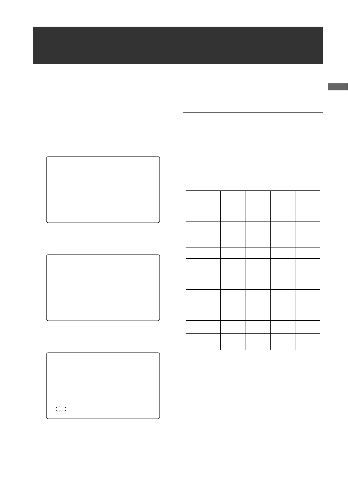
Recording Time on P2 Cards: When one 16 GB card is used;
HD Mode
Image system
1080-59.94i/
1
50i
*
1080-30PN/
25PN (Native)
1080-24PN
(Native)
*1 Including 30P, 24P, and 25P pull down of the DVCPRO HD
SD Mode
Image system
480-59.94i/576-50i
Recording method and Recording time
DVCPRO HD AVC-Intra100 AVC-Intra50
Approx.
16 minutes
-
-
Recording method and Recording time
2
*
Approx.
16 minutes
Approx.
16 minutes
Approx.
20 minutes
DVCPRO 50
Approx.32 minutes
Approx.
32 minutes
Approx.
32 minutes
Approx.
40 minutes
_ Built-in Time Code Generator/reader
A special-purpose Subcode track can be used to record
and reproduce time code information.
_ Support for Metadata
AJ-HPX3000 is capable of recording positional
information (latitudes, longitudes and altitudes), as
UMID information (metadata), from the GPS unit AJGPS910G (optional accessory). Names/titles can also
be recorded, e.g. the camera person, the reporter, or the
program which was registered on the SD memory card
in advance. This information is also useful in managing
information on clips. Regarding SD memory cards,
please also see
(page 22).
<Cautions in using SD memory cards>
*2 Including 30P, 24P, and 25P pull down
Notes
z
The values for 8 GB cards are 1/2 and the values for 4
GB cards are 1/4 those of 16 GB cards shown above.
z If the one-time continuous recording exceeds the
duration which is given in the table below when a P2
card with a memory capacity of 8GB or more is used
in AJ-HPX3000, the recording is automatically
continued on a separate clip. When performing
thumbnail operations (such as display, delete, repair
or copy) for these kinds of clips using a P2 device, it
is possible to perform the operations for the entire
recording as a single clip. However, with nonlinear
editing software or a personal computer, the
recording may be displayed as separate clips.
Recording method (except for native)
DVCPRO HD
AVC-Intra100
AVC-Intra50
DVCPRO 50
Continuous
recording time
Approx.
5 minutes
Approx.
10 minutes
General:Features of Recorder/player unit
10

Approximate Proxy Recording Time (optional) on SD memory cards
(Except for 24P native mode)
Card No.
(Card Capacity)
RP-SDH256
(256 MB)
RP-SDH512
RP-SDK512
(512 MB)
RP-SDQ01G
RP-SDK01G
(1 GB)
RP-SDQ02G
RP-SDK02G
(2 GB)
RP-SDV024G
(SDHC 4 GB)
MPEG4 recording rate
192 kbps 768 kbps 1500 kbps
Approx.
2 hour
17 minutes
Approx.
4 hour
27 minutes
Approx.
8 hour
56 minutes
Approx.
18 hour
11 minutes
Approx.
35 hour
42 minutes
Approx. 35
minutes
Approx. 69
minutes
Approx.
2 hour
19 minutes
Approx.
4 hour
44 minutes
Approx.
9 hour
18 minutes
Approx. 19
minutes
Approx. 38
minutes
Approx. 77
minutes
Approx.
2 hour
37 minutes
Approx.
5 hour
12 minutes
Features of the Input/Output unit
(Reference values when cards are used for continuous
recording with our products. Actual recording time depends
on the kind of scenes and the number of clips.)
The driver installed on the unit must be updated when
using SD memory cards other than as listed above. To
update the driver, refer to [Updating the firmware
incorporated into the camera-recorder] (page 193)
For the latest information on P2 cards and SD memory
cards not available in the operating Instructions, visit the
P2 Support Desk at the following Web sites.
https://eww.pavc.panasonic.co.jp/pro-av/
General
_ Features USB2.0 port (HOST/DEVICE)
By connecting with a PC via USB2.0, a P2 card inserted
in AJ-HPX3000 can be used as a bulk storage device.
It is also possible to store data on a P2 card onto a USB
2.0-connected external hard disk equipped with USB
host capability as well as view clips stored on hard disks
and write them to P2 cards. (Refer to page 135)
_ DVCPRO (IEEE1394) input/output provided as a
standard configuration
Data can be input/output to an external device through
the IEEE1394 digital interface. Use a 6-pin type
connector. The unit does not support the bus power.
While operating AVC-Intra, it is impossible to input/
output data with IEEE 1394. (Refer to page 133)
_ HD/SD SDI output featured as standard
Video can be output as HD SDI signals, down-converted
SD SDI signals, or analog composite signals. SDI output
includes embedded audio etc.. (Refer to page 44) Note
that the SD mode does not output HD SDI signals.
_ Down converter output provided as a standard
configuration
In HD mode, the MON OUT output connector and the
VIDEO OUT connector (in setting VBS mode) output
down converter (analog composite) signals.
It is optimum for confirming shot images on the SD
monitor. (Refer to page 44)
_ HD/SD SDI input function (when the AJ-
YA350AG is attached)
The camera-recorder with the AJ-YA350AG extension
board attached can record SDI signals input through the
SDI input connector only if the signals are in the same
format as the camera-recorder.
(The unit does not support the various Native methods.)
_ Remote control connector
By connecting the remote control unit (AJ-RC10G),
which is available as an optional accessory, the unit can
be controlled remotely. (Refer to page 111)
_ Confirmation of return video signals
It is possible to confirm the return video signals (analog
HD-Y signals in the HD mode/VBS or Y signals in the
SD mode) supplied to the GENLOCK IN connector of
AJ-HPX3000 in the viewfinder to confirm programs.
(Only video signals from the same record format can be
confirmed.) (Refer to page 178)
_ DC OUT connector
The DC OUT connector of the unit produces 1.5 A of
electrical current.
By connecting an external switch to this connector, it is
possible to control REC start/stop.
Since a tally lamp can be used by connecting the LED
to this connector, it is useful for shooting video when
fixing the camera on a crane. (Refer to page 112)
General:Features of the Input/Output unit
11

Other features
_ Viewfinder connection
From the viewfinder connector of the unit, 1080-59.94i,
1080-50i, 480-59.94i or 576-50i signals are output.
Furthermore, signals are output for switching the
frequencies of the connected viewfinder.
Confirm images in multi formats by connecting the
viewfinder (AJ-HVF21G), which is available as an
optional accessory. (Refer to page 28)
While the AJ-VF20WBP (59.94 Hz)/E (50 Hz) can also
be connected, you cannot view video in formats with
different frequencies.
Dimensions drawing
Unit: mm (inch)
3
137 (5- )
/
8
_ User button
On the side panel of the unit, three user buttons (USER
MAIN/USER1/USER2) are available.
Each button can be assigned the on/off function for any
frequently used feature selected from among the many
features of the unit, such as P2 card slot select (Refer to
page 51).
1
318 (12- )
/
2
16
/
1
102 (4- )
8
/
5
4
/
1
270.5 (10- )
209 (8- )
General:Other features
12
Color TV Standard Settings
(Settings for frame frequency)
The unit is delivered with the color TV standard not yet specified. To revise the settings for frame frequency according to the
preferred standard, refer to the procedures described below.
1 After connecting the unit to the power supply and then
turning on the power, press the MENU SW button while
pressing the LIGHT SW button to open OPTION
MENU.
2 Turn the JOG dial button to move the cursor (arrow) to
the AREA SELECT item on the AREA SETTING
screen in OPTION MENU, and the press the JOG dial
button.
*** OPTION M ENU ***
OPTION
#
AREA SETTIN G
3 Select the area among NTSC, NTSC(J), and PAL. After
selecting the area by turning the JOG dial button, press
the JOG dial button.
< AREA SETTI NG >
#
AREA SELECT : PAL
_AREA SET
4 Move the cursor (arrow) to _ AREA SET by turning
the JOG dial button, and then press the JOG dial button. The following window appears.
6 Turn off the power supply once and then turn on it
again.
◆Notes
z The settings are not saved unless SET is executed even if
NTSC, NTSC(J), or PAL is selected in the AREA SELECT.
z When AREA SELECT is revised, the “_ AREA SET”
blinks.
z When these items are set when the unit is used for the first
time, only the following 8 items are revised. When the
other settings of the unit are set in MAIN MENU, the
MENU setting values for items other than the following 8
are ones that were set at the factory.
Factory
settings
SYSTEM
MODE
CAMERA
MODE
SET UP*
D/C SET UP*
REAR LINE IN
LV L
AUDIO OUT
LV L
HEAD ROOM 20dB 20dB 20dB 18dB
GUI metadata
language
indication
LANGUAGE
DATA
FORMAT*
1080-
59.94i
60i 60i 60i 50i
1
7.5% 7.5% 0% 0%
2
7.5% 7.5% 0% 0%
+4dB +4dB +4dB 0dB
+4dB +4dB +4dB 0dB
American
English
Not
displayed
MDY MDY YMD DMY
3
NTSC NTSC(J) PAL
1080-
59.94i
American
English
Not
displayed
1080-
59.94i
Japanese/
For Japan
ENDLISH
JAPANESE
1080-50i
American
English
Not
displayed
General
AREA SET?
YES
#
NO
5 Move the arrow (→) to YES and press the JOG dial but-
ton. The settings selected in Step 3 above are reflected
in FACTORY and CURRENT DATA on the screen.
General:Color TV Standard Settings (Settings for frame frequency)
*1 SET UP of the DOWN CON SETTING menu
(Enabled only for 1080-59.94i)
*2 SET UP of the SYSTEM MODE menu
(Enabled only for 480-59.94i)
*3 Select THUMBNAIL > SETUP > DATA FORMAT from the
thumbnail menu. For details refer to [Setting the Thumbnail
Display Mode] (page 128).
13

System Configuration
Unislot wireless
microphone receiver:
Sennheiser EK3041
Stereo microphone
AJ-MC900G
Microphone holder:
AJ-MH800G
2-type HD Viewfinder:
AJ-HVF21G
Viewfinder:
AJ-VF15B
AJ-VF20WB
Lens:
(Bayonet type)
Fujinon, Canon
GPS unit:
AJ-GPS910G
:
Video encoder card:
AJ-YAX800G
Memory Card
Camera-Recorder
AJ-HPX3000G
◆Note
All of the devices and accessories other than the unit,
which are shown in this system configuration, are optionally available. To use these devices and accessories, refer
to the respective operation manuals.
Remote control cable:
AJ-C10050G
DIONIC90/160
HYTRON50/100/140
PROPAC14, TRIMPAC14
V mount type
Battery plate
NP-1 type
Battery case
External DC
power supply
Remote control unit:
AJ-RC10G
ENDURA7/10
BP-GL65/95
NP-L7
Tripod adapter:
SHAN-TM700
Rain cover:
SHAN-RC700
Soft carrying case:
AJ-SC900
Hard carrying case:
AJ-HT901G
* For the latest information on P2 cards and SD memory cards not available in the operating Instructions, visit the P2
Support Desk at the following Web sites.
https://eww.pavc.panasonic.co.jp/pro-av/
SD Memory cards*
HD/SD SDI input board:
AJ-YA350AG
P2 Cards*:
AJ-P2C004HG
AJ-P2C008HG
AJ-P2C016RG
General:System Configuration
14
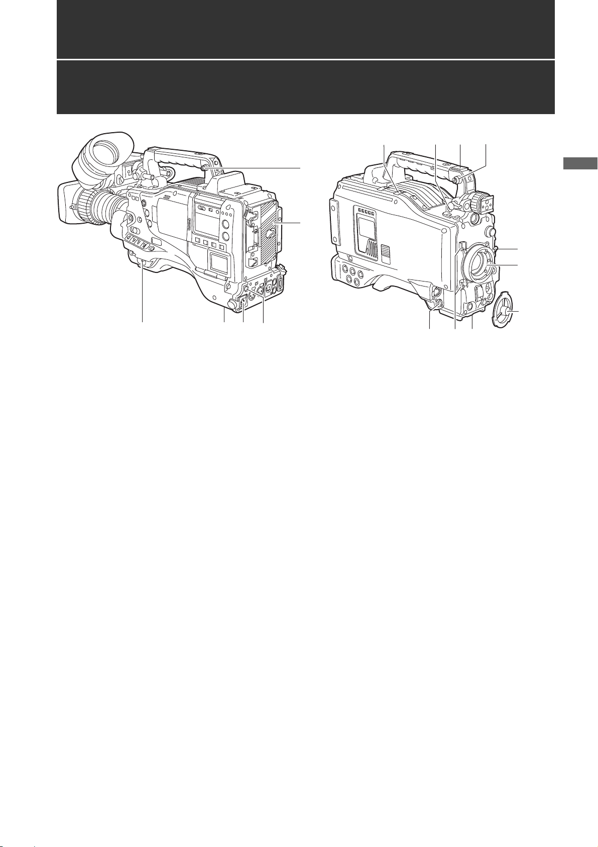
Parts and their Functions
Power Supply and Accessory Mounting Section
1
34
15
1. POWER switch
Used to turn on/off the power.
2. Battery mount
A battery pack from Anton/Bauer is mounted here.
3. DC IN (external power input) socket (XLR, 4P)
camera-recorder is connected to an external DC
power supply.
5
12
7
13
11
6
2
14
10.Lens mount cap
To remove the cap, raise the 9. lens lever.
When the lens is not mounted, replace the cap.
11.Light cable clamp
Secures the light cable.
12.Lens cable/microphone cable clamp
This clamp secures the lens and microphone cables.
6
Parts and their Functions
9
8
10
4. BREAKER switch
When an excessive amount of current is fed through
the camera-recorder, due to any abnormal event, the
breaker automatically turns off the power in order to
protect the device.
After the interior of the camera-recorder has been
checked and/or repaired, this button must be
depressed. If there is no unusual reaction, the unit can
be powered-up.
5. GPS connector
This connects the optional GPS unit AJ-GPS910G.
6. Shoulder strap fittings
The shoulder strap is attached here.
7. Light shoe
A video light or similar accessory can be attached
here.
8. Lens mount (bayonet 2/3-type)
The lens is attached here.
9. Lens lever
Lower this lever to lock the lens to the lens mount.
13.Tripod mount
When you want to mount camera-recorder on a tripod,
the optional tripod adapter (SHAN-TM700) is attached
here.
14.LENS jack (12-pin)
The lens connection cord is connected here. For a
detailed description of your lens, see the relevant
manufacturer’s instruction manual.
15.DC OUT (DC power supply) output socket
This output socket is designed for 12-VDC. It provides
a maximum current of 1.5 A.
Connect an external switch to this socket to control
REC starts and stops or an LED for use as a tally
lamp. For more information, see [Connection of the
external switch] (page 112).
Parts and their Functions:Power Supply and Accessory Mounting Section
15
Audio (input) Function Section
12
11
14 10
13
3
7
2
6
1
1. MIC IN (microphone input) jack (XLR, 5-pin)
A microphone (optional accessory) is connected here.
Power for the microphone comes from this jack.
A remote microphone may be connected. When a
microphone is used, set the power to ON through the
menu option FRONT MIC POWER.
These options are found in the <MIC/AUDIO2> screen
on the MAIN OPERATION page.
2. AUDIO LEVEL CH1/CH2 (audio channel 1 & 2
recording level adjustment) controls
With the 3. AUDIO SELECT CH1/CH2 switch
positioned to [MAN], these controls can be used to
adjust the recording levels for Audio Channels 1/2.
Note that the controls are designed to be locked. For
adjustment, each control must be depressed while
turning.
3. AUDIO SELECT CH1/CH2 (audio channel 1 &
2 automatic/manual level adjustment
selector) switch
Use this switch to select recording level control mode
for Audio Channels 1 and 2.
AUTO: Recording level automatically controlled.
MAN: Recording level manually controlled.
4. AUDIO IN (audio input selector) switch
Use this switch to select the signals recorded through
Audio Channels 1 - 4.
FRONT: Signal from the microphone connected to the
1. MIC IN jack is recorded.
W.L. (WIRELESS) :
Signal from the slot-in wireless receiver is
recorded.
REAR: Signal from the audio device connected to
the 5. AUDIO IN CH1/CH2 connector is
recorded.
815
4
5
9
Note
When you use stereo microphone (AJ-MC900G
optional), set both CH1 and CH2 to [FRONT]. The
signal from L CH is recorded to CH1 and that from R
CH to CH2.
5. AUDIO IN CH1/CH2 (audio input channel 1 &
2) connectors (XLR, 3-pin)
Audio devices or a microphone may be connected
here.
6.
LINE/MIC/+48V (line input/mic input/mic input +
48V) selector switch
Used to select the audio signal input from the 5.
AUDIO IN CH1/CH2 connectors.
LINE: Audio signal line-input from the audio device is
input.
MIC: Audio signal from a self-powered (active)
microphone is input. (The main unit does not
supply power to the remote microphone).
+ 48V:Audio signal from a passive microphone is
input. (The unit supplies power to the remote
microphone).
7. Wireless slot
A Unislot wireless receiver (optional accessory) may
be attached here.
8. FRONT AUDIO LEVEL (audio recording level
adjustment) control
This control adjusts the recording levels for Audio
Channels 1 and 2.
However, when the 3. AUDIO SELECT CH1/CH2
switch is set to “AUTO”, the level will adjust
automatically and the 2. AUDIO LEVEL CH1/CH2
knob and this knob will not be active.
The control can be enabled or disabled through the
menu options FRONT VR CH1 or FRONT VR CH2.
These options can be found in the <MIC/AUDIO1>
screen on the MAIN OPERATION page.
Parts and their Functions:Audio (input) Function Section
16

Audio (output) Function Section
9. AUDIO OUT connector (XLR, 5-pin)
This connector outputs audio signals recorded on
Channels 1/2 or 3/4.
Output signals are selected with the MONITOR
SELECT CH1/2 / CH3/4 selector switch.
10.MONITOR SELECT (audio channel) CH1/2 /
CH3/4 selector switch
Use this switch to select the audio channel whose
signals are output to the speakers, earphones or
AUDIO OUT connector.
CH1/2: Signals on Audio Channels 1 and 2 are output.
CH3/4: Signals on Audio Channels 3 and 4 are output.
The channel indications on the display window and on
the audio level meter in the viewfinder are
synchronised with this selector switch.
11.MONITOR SELECT (audio selection) CH1/3 /
ST / CH2/4 selector switch
The MONITOR SELECT switch is synchronised with
the audio signal output to the speakers and
earphones, and from the AUDIO OUT connector.
CH1/3: Signal on Audio Channel 1 or 3 is output.
ST: Stereo audio signals on Audio Channels 1
and 2 or Audio Channels 3 or 4 are output.
The stereo signals can be changed to mixed
signals using a menu option.
CH2/4: Signal on Audio Channel 2 or 4 is output.
14.Speakers
The speakers output EE sound during recording, and
reproduced sound during playback.
The speakers emit an alarm sound when the warning
lamp blinks and/or the indicator activates.
When the 15. PHONES jack is connected with
earphones, sound from the speaker is automatically
muted.
15.PHONES (earphones) jack (mini jack)
This connector is designed for audio monitoring
(stereo) earphones. When earphones are connected,
sound from the speakers is automatically muted.
Both the front and rear connectors output the same
sound.
Parts and their Functions
Monitor
switch
CH1/3 Audio Channel 1 Audio Channel 3
Stereo signals from
ST
CH2/4 Audio Channel 2 Audio Channel 4
* You can select between stereo and mixed signal
types using the menu option MONITOR SELECT.
This menu option can be found in the <MIC/
AUDIO2> screen on the MAIN OPERATION page.
MONITOR SELECT switch
CH1/2 CH3/4
Audio Channels 1
and 2*
Stereo signals from
Audio Channels 3
and 4*
12.MONITOR (volume) control
Used to control the volume of sound output from the
monitor speakers and earphones.
13.ALARM (warning alarm volume adjustment)
Used to control the volume of the warning sound
emitted from 14. speakers or earphones connected to
the 15. PHONES jack.
If the control is minimised, no alarm is audible.
Parts and their Functions:Audio (output) Function Section
17
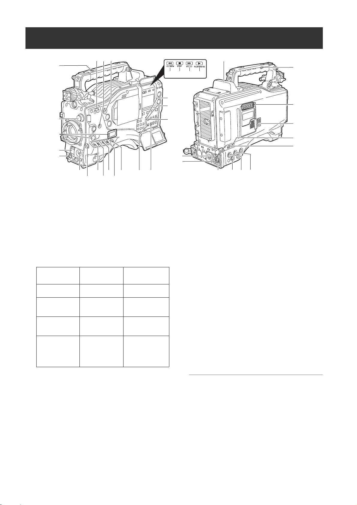
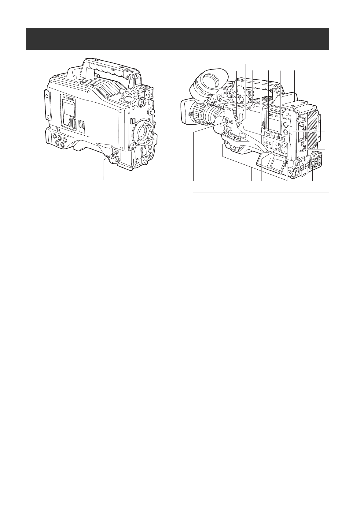
Shooting and Recording/Playback Functions Section
9
24
10
8
21
22
20
36
35
23
34
25
26
1
2
3
11
4
12
14
6
5
7
13
16
1. CC FILTER/ND FILTER (filter switching)
controls
These are used to select the filter in accordance with
the subject’s brightness and color temperature.
CC FILTER knob (outside, large diameter)
A : 3200K B : 4300K
C : 5600K D : 6300K
ND FILTER knob (inside, small diameter)
1 : CLEAR (transparent) 2 : 1/4 ND
3 : 1/16 ND 4 : 1/64 ND
Shooting
conditions
Sunrise, sunset,
inside a studio
Outdoors under a
clear sky
Outdoors under
cloudy or rainy
skies
Snowscapes, high
mountains,
seashores or
other perfectly
clear scenery
CC FILTER ND FILTER
A (3200 K) 1 (CLEAR)
B (4300 K) or
C (5600 K) or
D (6300 K)
D (6300 K)
B (4300 K) or
C (5600 K) or
D (6300 K)
2 (1/4 ND) or
3 (1/16 ND)
1 (CLEAR) or
2 (1/4 ND)
3 (1/16 ND) or
4 (1/64 ND)
19
15
17
33
18
32
31
30
3. SHUTTER switch
Used to enable or disable the electronic shutter.
OFF: Electronic shutter disabled.
ON: Electronic shutter enabled.
SEL: Used to change the speed of the electronic
shutter.
This dial switch returns to its original position. Each
turn of the switch alters the shutter speed.
For more information, see [
Shutter
] (page 49).
Setting the Electronic
4. AUTO W/B (white/black) BAL switch
AWB: White balance is automatically adjusted.
When the WHITE BAL switch on the side is
positioned at [A] or [B], the adjusted value is
stored in the memory.
Note that when the switch is positioned at
[PRST] this function does not work.
ABB: Back balance is automatically adjusted.
The automatic adjustment function of the black
shading can be assigned to this switch by
turning on the SHD.ABB SW CTL item on the
<SW MODE> page through menu operation.
(Refer to page 178)
27
28
29
2. USER MAIN, USER 1 and USER 2 buttons
These buttons can be assigned user-selected
functions, using a menu option. Each button, when
pressed, performs the assigned function.
For more information, see [
USER MAIN, USER1 and USER2 Buttons
Parts and their Functions:Shooting and Recording/Playback Functions Section
18
Assigning Functions to
] (page 51).
Note
To stop automatic adjustment of the white or black
balance in progress, set the switch to either ([AWB] or
[ABB]).
If automatic adjustment is cancelled, the value in effect
before automatic adjustment will be used.

5. Gain selector switch
Use this switch to select video amplifier gain,
according to lighting conditions under which you are
shooting.
The values for L, M, and H can be preset using menu
options.
These are factory-set to 0 dB for L, 6 dB for M, and 12
dB for H.
6. OUTPUT/AUTO KNEE selector switch
Used to select the video signals sent from the camera
unit to the memory, viewfinder and video monitor.
CAM. AUTO KNEE ON:
Video being recorded through the camera is sent
with the auto knee circuit activated.
It is also possible to assign the DRS (Dynamic Range
Stretcher) function instead of the AUTO KNEE
function.
CAM. AUTO KNEE OFF:
Video being recorded through the camera is sent in
manual knee mode.
BARS:
Color bar signal is output. The AUTO KNEE circuit
does not work.
You can select between four types of color bar signal.
For more information, see [SW MODE] (page 178).
Auto Knee function
Usually, when you adjust levels to shoot people or scenery
against a strongly lit background, the background will be totally
whited-out, with buildings and other objects blurred. In this case,
the AUTO KNEE function reproduces the background clearly.
This function is effective when:
•The subject is a person positioned in the shade under a clear
sky.
•The subject is a person inside a car or building, and you also
want to capture the background visible through a window.
•The subject is a high-contrast scene.
8. MODE CHECK button
Each press of this button changes the screen type in
the viewfinder in the following order: STATUS, !LED,
FUNCTION, AUDIO, CAC.
This does not affect the signal output from the camera.
9. MARKER SELECT button
This button selects the marker information indicated
on the viewfinder screen. It switches between two
marker information indications, which can be selected
using a menu option. Pressing this button once
switches the indicated marker information from A
(Marker A) to B (Marker B), and pressing again
switches B to OFF (no marker). When the power is
turned on, the last selected indication before powerdown appears.
For more information, see [
Displays (MARKER SELECT button function)
78).
Marker Check Screen
10.SYNCHRO SCAN ADJUSTMENT buttons
These buttons are enabled when the 3. shutter switch
is positioned at [ON] and synchro scan is selected.
They are used to adjust the speed of the synchro
scan.
The – button decreases shutter speed; the + button
increases shutter speed.
If you shoot a PC monitor, for example, you should
adjust shutter speed so that the horizontal bars in the
viewfinder will produce less noise.
11.REC START/STOP button
Pressing this button starts recording, pressing again
stops recording.
This button has the same function as the 24. REC
button on the handle and the VTR button at the lens.
Parts and their Functions
] (page
7. WHITE BAL (white balance memory selector)
switch
Used to select the white balance adjustment method.
PRST: Use this when you have no time to adjust the
white balance.
The value for the white balance is factory-set
to 3200 K.
It can be changed to any color temperature
using a menu option. For more information,
Setting Color Temperature Manually]
see [
(page 47).
A or B: Pressing the 4. AUTO W/B BAL Switch
toward [AWB] automatically adjusts the white
balance, saving the adjusted value in
Memory A or B. For more information, see
[Adjusting the White Balance] (page 45).
12.SHOT MARK/Menu cancel button
Pressing this button while recording adds a shot mark
to the thumbnail of that clip. This button also adds a
shot mark to any thumbnail selected on the LCD
monitor.
For more information on shot marks, see [
Function
This button cancels the revised set value when the
menu is displayed.
] (page 42).
Shot Mark
13.Text memo button
Records a text memo if pressed during recording or
playback or when playback is paused.
Parts and their Functions:Shooting and Recording/Playback Functions Section
19

24
10
9
8
21
22
20
36
35
23
34
25
26
1
2
3
11
19
4
12
14
6
5
7
13
16
14.SAVE ON/OFF switch
Used to select the power supply method for each
output section.
ON: The output selected through the menu option
SAVE SW is power-saved. This option can be
found on the OPTION MODE screen on the
SYSTEM SETTING page.
OFF: Power saving is canceled.
Note
The ON/OFF switch does not function during recording. The ON/OFF status changes after recording is
completed.
15.VIDEO OUT (output signal selector) switch
Changes the mode of the signals output through the
VIDEO OUT connector.
HD SDI : HD SDI signals are output. When the
camera-recorder is in SD mode, SD SDI
signals are output.
SD SDI : SD SDI signals are output.
: Composite video signals are output.
VBS
16.VIDEO OUT CHARACTER switch
This switch controls the superimposition of characters
onto the video output from the VIDEO OUT connector.
ON: Characters are superimposed.
OFF: Characters are not superimposed.
For types of characters, see [
from VIDEO OUT connector
Settings of signals output
] (page 80).
17.VIDEO OUT (video signal output) connector
This connector outputs video signals. The video
signals linked to the settings of 15. VIDEO OUT
switch, 16. VIDEO OUT CHARACTOR switch and
19.OUTPUT SEL switch are output from here. For
more details, refer to [
VIDEO OUT connector
Settings of signals output from
] (page 80).
15
17
33
32
18
31
30
27
28
29
18.MON OUT (monitor output) connector
Used to output down-converted (analog composite)
signals for the monitor. The video signals linked to the
setting of the OUTPUT SEL switch are output from
here. Through an internal menu option, the characters
can be superimposed independently of the VIDEO
OUT connector. For more information, see [
signals output from MON OUT connector
] (page 81).
19.OUTPUT SEL (output signal selection) switch
Used to switch the signals output from the VIDEO
OUT and MON OUT connectors.
MEM: Video from the camera is output during
recording or when recording is paused or
playback signals are output from the P2 card
during playback.
CAM: Video from the camera is output constantly.
OFF: Video is not output, and the camera-recorder
operates in power-saving mode.
Note that the audio output is synchronised with the
video.
For types of video outputs, see [
output from VIDEO OUT connector
[
Settings of signals output from MON OUT connector]
(page 81).
Notes
z During recording, this switch does not switch output
signals before stopping the recording operation.
z When CAM is not selected through the REC
SIGNAL menu option, the output signals are the
same as for MEM even if the switch is set to CAM.
The menu option REC SIGNAL is found in the
SYSTEM MODE screen on the SYSTEM SETTING
page.
Settings of signals
] (page 80) or
Settings of
Parts and their Functions:Shooting and Recording/Playback Functions Section
20

20.REW (rewind) button and lamp
During pause, this button performs a fast-reverse
playback with the lamp blinking.
During playback, it performs an approximately 4
reverse playback with the PLAY and REW lamps
blinking.
If this button is pressed when playback is paused, the
start of the clip being played back is located in pause
mode.
21.STOP button
This button stops playback.
22.FF (fast forward) button and lamp
During pause, this button is used to perform fast
playback with the lamp blinking.
During playback, it performs an approximately 4
playback with the PLAY and FF lamps blinking.
If this button is pressed when playback is paused, the
start of the next clip is located in pause mode.
23.PLAY/PAUSE button
This button is used to view playback using the
viewfinder screen or a color video monitor. The lamp
comes on when playback starts.
In playback mode, this button pauses (PLAY PAUSE)
playback with the lamp blinking.
24.REC button
Pressing this button starts recording, and pressing
again stops recording.
This button has the same function as 11. the REC
START/STOP button and the VTR button at the lens.
It may be disabled with 25. the REC protection button.
a fast-
a fast
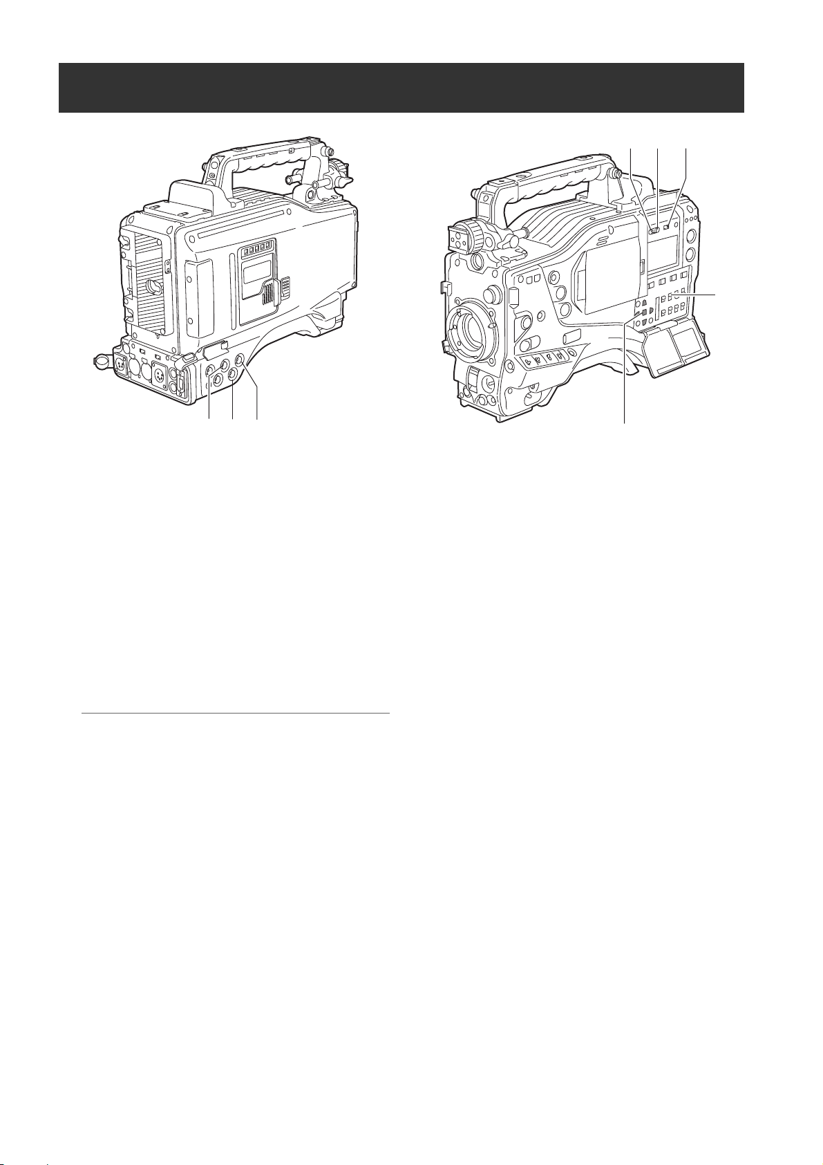
30.GENLOCK IN connector
Used to input an HD Y signal when GENLOCKing the
camera or externally locking the time code.
Alternatively, a composite signal can be input as the
reference signal. Note that the subcarriers for the
down-converter (composite signal) output from the
camera-recorder cannot be externally locked.
Notes
z When HD Y signal is input and CAM RET is
selected, you can check return video on the
viewfinder screen. The menu option RET SW can be
found in the SW MODE screen on the CAM
OPERATION page.
z When the mode is set to SD, you can record original
signals by specifying VIDEO for the menu option
REC SIGNAL.
31.SDI OUT/IN (option) connector
The default setting outputs the same SDI signals as
the SDI signals from the VIDEO OUT connector. When
the VIDEO OUT switch is set to VBS, HD SDI signals
are output in the HD mode while SD SDI signals are
output in the SD mode.
If installed, the optionally available HD/SD SDI input
board (AJ-YA350AG,
input connector for HD/SD SDI signals. You can record
signals from this input connector by specifying SDI for
the menu option REC SIGNAL. For details, refer to
[Connection using the SDI IN connector (when AJYA350AG attached)] (page 141).
optional accessory) acts as an
Parts and their Functions
25.REC protection button
This button disables 24. the REC button on the handle.
ON: The REC button is enabled.
OFF: The REC button is disabled.
26.P2 CARD ACCESS LED
This LED indicates the recording and playback status
of each card.
27.Slide lock button
Used to open the slide-out door for inserting P2 cards.
While depressing this button, slide the door to the left.
28.USB 2.0 connector (DEVICE)
29.USB 2.0 connector (HOST)
A USB 2.0 cable is connected here.
When the menu option PC MODE is set to “ON”, data
can be transferred via USB 2.0. During such data
transfer, recording, playback or operations of clips is
permitted.
The menu option PC MODE is found in the SYSTEM
MODE screen on the SYSTEM SETTING page. For
more information, see [Connection with external
devices using the USB 2.0 port] (page 135).
Parts and their Functions:Shooting and Recording/Playback Functions Section
21

32.DVCPRO connector
This is an in/output connector for video, voice, and
data that comply with the IEEE1394 standard. It is
impossible to input/output the DV signal.
35.SD memory card insertion slot
An SD memory card (optional accessory) is inserted
here.
SD memory cards are used for uploading meta-
data, and proxy recording (optional).
Notes
z Power is not supplied from the unit.
z Be absolutely sure to bear the following points in
mind when connecting the IEEE1394 cable (DV
cable).
Ensure that the connections with other devices are
made on a 1:1 basis.
When an IEEE1394 cable has been connected to
the DVCPRO connector, do not apply any strong
external force as this may damage the connector.
When error code 1394 E-92 (1394 INITIAL
ERROR) appears, disconnect the connecting
cables and re-connect them or turn off the
camera-recorder’s power and turn it back on.
Ensure that the unit and all of the connected
devices are each grounded (or connected to a
common ground) before use.
If it is not possible to ground the unit and devices,
turn off the power of the unit and of all the
connected devices before connecting or
disconnecting the IEEE1394 cable.
When the unit is to be connected to a device
equipped with a 4-pin type of connector, connect
the unit’s connector (6-pin type) first.
When connecting the unit
with a PC equipped with
a 6-pin type ofconnector,
connect the IEEE1394
cable as dictated by the
shapes of the 1394
connectors. Bear in mind
that inserting a plug the wrong way round may
damage the unit.
When the unit is used in AVC-Intra format, image/
voice signals cannot be output/input through the
DVCPRO connector.
6-pin type
4-pin type
33.REMOTE (remote control) connector
The remote control unit AJ-RC10G (optional
accessory) is connected here.
Note
For software of the AJ-RC10G, use Version 1.10-00000 or higher.
<Cautions in using SD memory cards>
Use the unit by inserting an SD memory card that is
compliant with the SD standard or the SDHC standard.
MultiMediaCards cannot be used. (Bear in mind that
taking pictures may no longer be possible if you do use
them.)
If you intend to use miniSD cards in camera-recorder,
always install the adapter specially designed for
miniSD cards. (The unit will not work properly if only
the miniSD card adapter is installed. Make sure that
the card has been installed in the adapter before using
it.)
Use of Panasonic’s SD memory cards and miniSD
cards is recommended. Be sure to format cards using
camera-recorder.
To format SD memory cards using a personal
computer, download the dedicated software from the
support site.
Any SD memory card with the following capacities (8
MB to 2 GB) and any 4 GB SDHC memory card can
be used with the unit.
8 MB 16 MB 32 MB 64 MB
128 MB 256 MB 512 MB 1 GB
2 GB 4 GB (SDHC)
To record proxy (optional), use an SD memory card with
a capacity of 256 MB, 512 MB, 1 GB, or 2 GB labeled
“High Speed” or use a 4 GB SDHC memory card.
For the latest information not available in the operating
Instructions, visit the P2 Support Desk at the following
Web sites.
https://eww.pavc.panasonic.co.jp/pro-av/
z The SDHC card conforms to a new standard for memory
cards with a large capacity of more than 2 GB which was
established by the SD Association in 2006.
z The SD card logo is a registered trademark.
z MMC (MultiMediaCard) is a registered trademark of Infineon
Technologies AG.
36.BUSY (operation mode display) lamp
This lamp indicates the active status of the SD
memory card.
It stays illuminated when the card is active.
34.OPTION SLOT
Attach the video encoder card (AJ-YAX800G,
optional). For information about the installation and
proxy recording, see the AJ-YAX800G instruction
manual.
Parts and their Functions:Shooting and Recording/Playback Functions Section
22
Note
While the lamp is on, do not insert or remove the card.
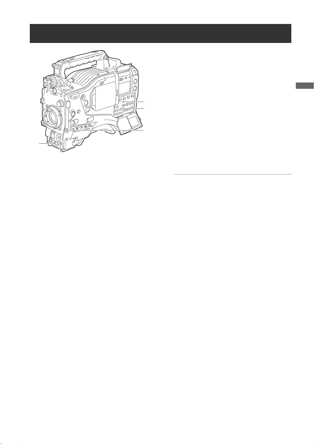
Menu Operation Section
1. MENU button
Used to turn on/off the menu.
2. JOG dial button
With the menu open, this button is used to navigate
through menu pages, select options and specify
values.
For directions on manipulating the menu, see [Setting
4
3
5
Menu Options] (page 157).
3. SD memory card insertion slot
An SD memory card (optional accessory) is inserted
here. It is used when writing or saving menu data or
lens files on an SD memory card.
Parts and their Functions
2
1
4. BUSY (operation mode display) lamp
This lamp indicates the active status of the SD
memory card.
It stays illuminated when the card is active.
Note
While the lamp is on, do not insert or remove the card.
5. Shot Mark/Cancel Menu button
Undoes any changes to the menu option settings if
pressed during the changes
Parts and their Functions:Menu Operation Section
23
Time Code Section
6
5
4
7
13
2
1. GENLOCK IN connector (BNC)
This connector is used to input a reference signal
before the camera unit is gen-locked, or before the
time code is externally locked.
2. TC IN connector (BNC)
This connector is used to input a reference time code
when you externally lock the time code.
3. TC OUT connector (BNC)
When you inter-lock the time code of camera-recorder
with that of an external device this must be connected
with the time code input (TC IN) connector of the
external device.
Note
The time code must be input in the same format as the
system mode of the camera-recorder.
4. HOLD button
Pressing this button freezes the time data indication
on the counter. Note that time code generation
continues. Pressing the button again reactivates the
counter.
This function is used to ascertain the time code or CTL
count of a particular recorded scene.
8
6. DISPLAY (counter display selector) switch
Indications of the time code, CTL and user bits on the
counter of the display window depend on the positions
of this switch and the 7.TCG switch.
Pressing the 4.HOLD button also displays Date/Time/
Time Zone.
UB: User bits/DATE/TIME/Time zone indicated.
TC: Time code indicated.
CTL: CTL indicated.
7. TCG (time code selector) switch
This switch is used to specify the stepping mode for
the built-in time code generator.
F-RUN: Select this position to continuously advance
the time code independently of the P2 card
recording status.
Use this mode to synchronise the time code
with the time of day, or to externally lock the
time code.
SET: Select this position to set the time code and/
or user bits.
R-RUN: Select this position to advance the time code
only during recording.
For spliced scenes recorded on P2 cards,
the sequence of time codes is unbroken.
5. RESET button
This button resets the time data (CTL) on the counter
to “00:00:00:00”.
If this button is pressed when with the 7.TCG switch
positioned at [SET], time code and user bits data are
reset to 0, and real-time data is reset to the initial
value.
Parts and their Functions:Time Code Section
24
8. CURSOR and SET buttons
Use these buttons to set the time code and user bits.
The four triangular buttons are the CURSOR buttons,
and the center rectangular one is the SET button.
For guidance in setting the time code and user bits,
see [
Setting Time Data] (page 55).
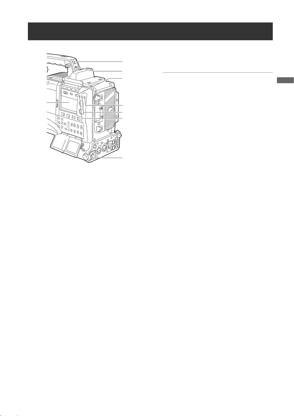
Warning and Status Display Functions
1
2
6
7
1. Back tally lamp
When the 2.BACK TALLY switch is set to [ON], the
lamp behaves in the same way as the front tally lamp
at the viewfinder.
3
4
5
8
7. Display window
This window displays warnings, battery-remaining
level, sound volume, time data, and other information.
Note
When the battery is installed, the camera-recorder
indicates the data even if the power is turned off. To
turn off the data indications to keep the battery from
being discharged, specify OFF for the menu option P.
OFF LCD DISPLAY found in the TC/UB screen on the
MAIN OPERATION page.
8. Rear tally lamp
When the 2.BACK TALLY switch is set on [ON], the
rear tally lamp behaves in the same way as the back
tally lamp.
Parts and their Functions
2. BACK TALLY switch
This switch controls the action of the 1.back and 8.rear
tally lamps.
ON: Back and rear tally lamps enabled.
OFF: Back and rear tally lamps disabled.
3. WARNING lamp
This lamp starts blinking or lights up if something
unusual occurs in the memory.
4. USB lamp
Stays on when the camera-recorder is in USB mode.
5. Access lamp
Blinks when the camera-recorder is in recording or
playback mode or when a P2 card is being accessed,
or stays on when a recordable P2 card is inserted.
6. LIGHT button
Use this button to control illumination of the display
window.
Alternately pressing this button toggles illumination of
the 7.display window on or off.
Parts and their Functions:Warning and Status Display Functions
25

Display Window Functions
P2 card/battery-remaining level indications
Media-remaining space indication bar
The bar indicates the remaining free space on each P2 card,
using a seven-segment display.
Each segment can represent either three or five minutes of
remaining free space, depending on the value set through the
menu option CARD REMAIN/
segments disappear one-by-one. The menu option CARD
REMAIN /
on the MAIN OPERATION page.
can be found in the <BATTERY/P2CARD> screen
SLAVE HOLD W GPS
NDF
VTCG
CTL
h
MEDIA
BATT
TIME DATE
Y minM
E
EF
LOOP
Battery-remaining level indication bar
For a battery with a digital indicator (percentage
indication), if the remaining level of the battery is higher
than 70%, all seven segments up to the “F” position are lit.
When the remaining level falls below 70%, the segments go out
one-by-one for each drop of 10%. All seven segments can be set
to light up when the battery-remaining balance is 100%. To do so
select “100%” for the menu option BATT REMAIN FULL in the
<BATTERY/P2CARD> screen of the MAIN OPERATION page.
Audio channel level meter
When the MONITOR SELECT CH1/2 / CH3/4 switch is set to
[CH1/2], the meter indicates 1 and 2 as the audio channel
numbers, together with their audio levels. When the switch is
set to [CH3/4], the meter indicates 3 and 4 as the audio
channel numbers, together with their audio levels.
. According to the set value, the
HD
OVER OVER
0
P-iREC
10
s
D
OP-SLOT
frm
F
18
30
40
OO
-dB
13 24
Memory action status indication
Error Code Indication (for more information, see
[Warning System] (page 149))
frm
OVER OVER
F
13 24
Loop Recording
-dB
0
10
18
30
40
OO
SLAVE HOLD W GPS
NDF
VTCG
CTL
h
MEDIA
BATT
TIME DATE
Y minM
E
EF
LOOP
Information indication
LOOP:
OP-SLOT: Remains illuminated when a video encoder card is
Stays illuminated in LOOP REC mode. For information
about the LOOP REC mode, see [
(page 37).
operated in the optional slot.
HD
P-iREC
s
D
OP-SLOT
Mode indication
W: Stays illuminated when the camera-recorder operates
in SD mode (480-59.94i, 576-50i) and is set to 16:9
HD: Stays illuminated when the camera-recorder is in HD
GPS: Stays illuminated when radio waves are not received
GPS : Stays illuminated when radio waves are received
P-REC: Stays illuminated when the PRE REC MODE is set to
iREC: Remains illuminated during INTERVAL REC mode
i: Blinks when INTERVAL REC mode is selected.
Time code indication
NDF: Stays illuminated when the time code is in non-drop
DF: Stays illuminated when the time code is in drop frame
SLAVE
HOLD: Stays illuminated when the time code generator/reader
CTL: Stays illuminated when the DISPLAY switch is
TCG: Stays illuminated when the DISPLAY switch is
TC:
VTCG: Stays illuminated when the DISPLAY switch is
VTC: Stays illuminated when the DISPLAY switch is
TIME:
DATE: Stays illuminated when the DISPLAY switch is
No Indication:
Time count indication:
Note
When the DISPLAY switch is positioned at UB, each press of the
HOLD button changes the indication through VTCG (VTC)
]
>
mode.
mode (1080i).
during GPS operation.
during GPS operation.
ON, and blinks when recording is continued after the
recording tally lamp has gone out.
recording, and blinks during a pause.
NDF
SLAVE HOLD W GPS
VTCG
CTL
h
MEDIA
BATT
TIME DATE
Y minM
E
EF
LOOP
frame mode.
mode.
: Stays illuminated when the time code is externally
locked.
value is frozen.
positioned at [CTL] to display the CTL count.
positioned at [TC] (or [UB]) to display the TC (or UB)
generator value.
Stays illuminated when the DISPLAY switch is positioned at
[TC] (or [UB]) to display the TC (or UB) reader value.
positioned at [UB] to display the VIUB generator value.
positioned at [UB] to display the VIUB reader value.
Stays illuminated when the DISPLAY switch is positioned at
[UB] to display the real-time hour, minute and second.
positioned at [UB] to display the real-time date.
The CTL, VTCG, TIME, and DATE stay off when the DISPLAY
switch is positioned at [UB] to display real time, time zone,
hour and minute.
The time code, CTL, user bits and real time are shown.
TIME > No Indication (Time Zone) > TCG (TC), in that order.
HD
P-iREC
s
D
OP-SLOT
OVER OVER
frm
F
13 24
-dB
0
10
18
30
40
OO
>
DATE
Parts and their Functions:Display Window Functions
26

LCD Monitor
5. CURSOR and SET buttons
The four triangular buttons are the CURSOR buttons,
1
and the center rectangular one is the SET button.
They are used to select a thumbnail and manipulate
the thumbnail menu. For more information, see
[Manipulating Clips with Thumbnails] (page 113).
Parts and their Functions
6. EXIT button
Used to return the display to the previous state when
the thumbnail menu or the property screen is
displayed.
23
5
6
4
1. LCD monitor
The LCD monitor displays the video in the viewfinder.
Alternatively, it can show clips on the P2 card in a
thumbnail format.
In thumbnail display mode, clips can be edited or
deleted, or P2 cards can be formatted using the
4.THUMBNAIL MENU button and 5.CURSOR and
SET buttons.
2. OPEN button
Used to open the LCD monitor.
3. THUMBNAIL button
This button switches the content on the 1.LCD monitor
from the video in the viewfinder to clip thumbnails.
Another press switches them back to the video from
the viewfinder.
Note that this switchover is not performed during a
recording or playback.
4. THUMBNAIL MENU button
In thumbnail display mode, this button allows you to
manipulate the thumbnail menu (e.g., to delete clips).
Parts and their Functions:LCD Monitor
27

Viewfinder
You can use any of the following viewfinders (extra-cost options) on AJ-HPX3000:
HD Viewfinders: AJ-HVF21G (selectable between 59.94 and 50 Hz)
SD Viewfinders: AJ-VF20WBP (59.94 Hz), AJ-VF15BP (59.94 Hz), AJ-VF20WBE (50 Hz), and AJ-VF15BE (50 Hz)
Use the VF TYPE menu options on the SYSTEM MODE screen on the SYSTEM SETTING page to adjust the appropriate
settings for the viewfinder that will be used. We recommend using a HD viewfinder when the camera-recorder is used in
HD mode or an SD viewfinder when it is used in SD mode. Depending on the mode, some types of video are unavailable
as shown below (
z: the finder shows nothing on a black screen).
Mode
HD
SD
Video seen through
viewfinder
Video from camera
Playback ±±*1*
Return video (HD-Y) ± z
1394/HD-SDI input (HD) ±±*
Video from camera
Playback z ±
Return video (VBS) z ±
1394/HD-SDI input (SD) z ±
HD viewfinder SD viewfinder
±±*
±±
1
2
1
Each viewfinder shows return signals and 1394 and SDI input signals in the recording formats assigned to the camerarecorder.
*1: Down-converted signals
*2
: When the OUTPUT SEL switch of the camera-recorder is set to CAM, a black screen is displayed.
Parts and their Functions:Viewfinder
28

13 14 11 7
9
9. Eyepiece
10
12
1
8
23
45 6
1. Viewfinder (optional accessory)
During recording or playback, the viewfinder displays
the video image in monochrome. It also displays
warnings, messages, zebra patterns, markers (safety
zone and center markers), etc.
2. ZEBRA (zebra pattern) switch
This switch is used to display the zebra pattern in the
viewfinder.
ON: Zebra pattern displayed.
OFF: No zebra pattern displayed.
3. TALLY switch
Used to control the 7.front tally lamp.
Note
Do not leave the eyepiece aimed at the sun. Doing so
may damage the internal components.
10.Diopter adjustment ring
Use this to make adjustments in line with your diopter,
in order to obtain optimum clarity in the viewfinder
image.
The adjustable range of the viewfinder view angle is
shown in the following table.
Product Number Adjustable range
AJ-HVF21G
AJ-VF20WBP
AJ-VF20WBE
AJ-VF15BP
AJ-VF15BE
For an eyepiece for presbyopia, consult the dealer.
–0.9 D to –4.4 D
+1.1 D to –3.4 D
11.Connecting plug
12.Locking ring
13.Microphone holder
Parts and their Functions
HIGH: Front tally lamp brightly illuminated.
OFF: Front tally lamp stays off.
LOW: Front tally lamp dimly illuminated.
4. PEAKING control
Used to adjust the outlines of the video image in the
viewfinder for easier focusing. This does not affect the
signal output from the camera.
5. CONTRAST control
Used to adjust the contrast of the video image in the
viewfinder. This does not affect the signal output from
the camera.
6. BRIGHT control
Used to adjust the brightness of the video image in the
viewfinder. This does not affect the signal output from
the camera.
7. Front tally lamp
This lamp is activated when the 3.TALLY switch is
positioned at [HIGH] or [LOW], and stays on during
recording. It also blinks in synchronisation with the
REC lamp in the viewfinder, and provides alerts.
Use the TALLY switch to change the intensity of the
lamp to ([HIGH] or [LOW]).
14.Viewfinder stopper
Used to attach or remove the viewfinder.
16
15
15.Viewfinder left-right position anchoring ring
Used to adjust the side-to-side position of the
viewfinder.
16.Viewfinder front-back position anchoring
lever
Used to adjust the fore-and-aft position of the
viewfinder.
8. Back tally lamp
This lamp stays illuminated during shooting. It also
blinks in synchronisation with the REC lamp in the
viewfinder, and provides alerts.
When the lever is positioned at [OFF], the back tally
lamp is hidden.
Note
For more information, see the instruction manual for
the viewfinder.
Parts and their Functions:Viewfinder
29

Recording and Playback
P2 Cards
Inserting P2 Cards
Note
When using the camera-recorder for the first time, be sure
to set the time data beforehand. On how the time data is
set, see [
Setting Time Data] (page 55).
1 Turn on the POWER switch.
POWER: ON
2 While pressing down the slide lock button, slide the
slide-out door to the left.
The door opens.
3 Insert a P2 card into the P2 card slot until the EJECT
button pops up.
EJECT button
The card must be
inserted with the
logo right way
up.
4 Tilt up the popped-up EJECT button, to lock-in the P2
card.
P2 CARD
ACCESS
LED
Recording and Playback:P2 Cards
30
Slide-out door
Slide lock
button
5 Insert a P2 card into camera-recorder. The P2 CARD
ACCESS LED for the appropriate slot indicates the
status of the P2 card.
For how the P2 card status is indicated, see [P2
CARD ACCESS LED and status of P2 cards] (page
31).
6 Close the slide-out door.
Note
Do not leave the slide-out door open when moving
camera-recorder.
 Loading...