

Page 1

Operating Instructions
Memory Card Camera-Recorder
Model No. AJ-HPX2000P
Before operating this product, please read the insructions carefully and save this manual for future use.
To use AVC-Intra, the AVC-Intra codec board (AJ-YBX200G/optional) must be installed.
F1206T1077 -F @
Printed in Japan
ENGLISH
VQT1D27-1
Page 2
Read this first!
CAUTION
RISK OF ELECTRIC SHOCK
DO NOT OPEN
CAUTION: TO REDUCE THE RISK OF ELECTRIC SHOCK,
REFER TO SERVICING TO QUALIFIED SERVICE PERSONNEL.
DO NOT REMOVE COVER (OR BACK).
NO USER SERVICEABLE PARTS INSIDE.
The lightning flash with arrowhead symbol,
within an equilateral triangle, is intended to
alert the user to the presence of uninsulated
“dangerous voltage” within the product’s
enclosure that may be of sufficient magnitude
to constitute a risk of electric shock to persons.
The exclamation point within an equilateral
triangle is intended to alert the user to the
presence of important operating and
maintenance (service) instructions in the
literature accompanying the appliance.
WARNING:
zTO REDUCE THE RISK OF FIRE OR SHOCK
HAZARD, DO NOT EXPOSE THIS
EQUIPMENT TO RAIN OR MOISTURE.
zTO REDUCE THE RISK OF FIRE OR SHOCK
HAZARD, KEEP THIS EQUIPMENT AWAY
FROM ALL LIQUIDS. USE AND STORE ONLY
IN LOCATIONS WHICH ARE NOT EXPOSED
TO THE RISK OF DRIPPING OR SPLASHING
LIQUIDS, AND DO NOT PLACE ANY LIQUID
CONTAINERS ON TOP OF THE EQUIPMENT.
CAUTIONS:
TO REDUCE THE RISK OF FIRE OR SHOCK
HAZARD AND ANNOYING INTERFERENCE,
USE THE RECOMMENDED ACCESSORIES
ONLY.
CAUTIONS:
In order to maintain adequate ventilation, do not
install or place this unit in a bookcase, built-in
cabinet or any other confined space. To prevent risk
of electric shock or fire hazard due to overheating,
ensure that curtains and any other materials do not
obstruct the ventilation.
CAUTION:
This equipment has been tested and found to comply with the
limits for a Class B digital device, pursuant to Part 15 of the FCC
Rules. These limits are designed to provide reasonable
protection against harmful interference in a residential
installation. This equipment generates, uses and can radiate
radio frequency energy, and if not installed and used in
accordance with the instructions, may cause harmful
interference to radio communications. However, there is no
guarantee that interference will not occur in a particular
installation. If this equipment does cause harmful interference
to radio or television reception, which can be determined by
turning the equipment off and on, the user is encouraged to try
to correct the interference by one of the following measures:
z Reorient or relocate the receiving antenna.
z Increase the separation between the equipment and
receiver.
z Connect the equipment into an outlet on a circuit different
from that to which the receiver is connected.
z Consult the dealer or an experienced radio/TV technician for
help.
The user may find the booklet “Something About Interference”
available from FCC local regional offices helpful.
FCC Warning: To assure continued FCC emission limit
compliance, the user must use only shielded interface cables
when connecting to host computer or peripheral devices. Also,
any unauthorized changes or modifications to this equipment
could void the user’s authority to operate this device.
Declaration of Conformity
Model Number: AJ-HPX2000P/AJ-HPX2100E
Trade Name: PANASONIC
Responsible Party: Panasonic Corporation of North America
One Panasonic Way, Secaucus, NJ 07094
Support contact: Panasonic Broadcast & Television Systems
Company 1-800-524-1448
This device complies with Part 15 of FCC Rules. Operation is
subject to the following two conditions:
(1) This device may not cause harmful interference, and (2) this
device must accept any interference received, including
interference that may cause undesired operation.
To assure continued compliance, follow the attached
installation instructions and do not make any unauthorized
modifications.
CAUTIONS:
TO REDUCE THE RISK OF FIRE OR SHOCK
HAZARD, REFER MOUNTING OF OPTIONAL
INTERFACE BOARDS TO QUALIFIED SERVICE
PERSONNEL.
indicates safety information.
A rechargeable battery that is recyclable powers the product you have purchased.
<For USA-California Only>
This product contains a CR Coin Cell Lithium Battery which contains Perchlorate Material — special handling may apply.
See www.dtsc.ca/gov/hazardouswaste.perchlorate.
Caution regarding laser beams
The CCD may be damaged if it is subjected to light from a laser beam.
When using the camera-recorder in locations where laser irradiation equipment is used, be careful not to allow
the laser beam to shine directly on the lens.
2
Page 3

Attention/Attentie
ENGLISH
z Batteries are used for the main power source and memory back-up in the product.
At the end of their useful life, you should not throw them away.
Instead, hand them in as small chemical waste.
NERDERLAND
z Voor de primaire voeding en het reservegeheugen van het apparaat wordt gebruikgemaakt van
een batterij.
Wanneer de batterij is uitgeput, mag u deze niet gewoon weggooien, maar dient u deze als
klein
chemisch afval weg te doen.
TO REMOVE THE BATTERY
Main Power Battery (Ni-Cd / Ni-MH / Li-ion Battery)
z To detach the battery, please proceed in the reverse order of the installation method described in this manual.
z If a battery made by any other manufacturer is to be used, check the Operating Instructions accompanying the battery.
Back-up Battery (Lithium Battery)
z For the removal of the battery for disposal at the end of its service life, please consult your dealer.
PLEASE NOTE:
z When preparing to record important images, always shoot some advance test footage, to verify that both pictures and
sound are being recorded normally.
z Should video or audio recording fail due to a malfunction of this camera-recorder or the P2 cards used, we will not assume
liability for such failure.
z If the unit is operated continuously with the fan stopped due to a failure, camera images may not be output, recorded, or
played back properly.
What to remember when throwing memory cards away or transferring them to others
Formatting memory cards or deleting data using the functions of the unit or a computer will merely change the file
management information: it will not completely erase the data on the cards. When throwing these cards away or transferring
them to others, either physically destroy them or use a data deletion program for computers (commercially available) to
completely erase the data. Users are responsible for managing the data on their memory cards.
3
Page 4

Contents
Read this first! ..................................................................................2
General Features of Camera unit....................................................................8
Features of Recorder/player unit .......................................................9
Features of the Input/Output unit .....................................................11
Other features .................................................................................11
Dimensions drawing........................................................................12
System Configuration......................................................................13
Parts and their Functions Power Supply and Accessory Mounting Section............................14
Audio (input) Function Section.......................................................15
Audio (output) Function Section.....................................................16
Shooting and Recording/Playback Functions Section ...................17
Menu Operation Section ................................................................22
Time Code Section.........................................................................23
Warning and Status Display Functions ..........................................24
Display Window Functions .............................................................25
LCD Monitor ...................................................................................26
Viewfinder ......................................................................................27
Recording and Playback P2 Cards.........................................................................................29
How to handle data recorded on P2 cards .......................................31
Basic Procedures ............................................................................32
Normal Recording ...........................................................................34
PRE-RECORDING function ............................................................35
Loop Recording...............................................................................36
Interval Recording ...........................................................................36
Recording Review Function.............................................................39
Normal and Variable Speed Playback .............................................40
Text Memo Function .......................................................................40
Adjustments and Settings for
Recording
4
Shot Mark Function .........................................................................41
Recording Setting and Operation Mode...........................................41
Multi Format....................................................................................42
Adjusting the White balance and Black Balance ..............................45
Setting the Electronic Shutter ..........................................................49
Assigning Functions to USER MAIN, USER1 and USER2 Buttons ..51
Selecting Audio Input Signals and Adjusting Recording Levels........53
Page 5

Setting Time Data ...........................................................................55
Viewfinder Screen Status Displays ..................................................69
Adjusting and setting the LCD monitor ............................................80
Selection of video output signals .....................................................81
Handling data..................................................................................83
Preparation Power Supply..................................................................................97
Mounting the lens and Performing the Flange Back and
White Shading Adjustments
Preparing for Audio Input ..............................................................104
Mounting the Camera on a Tripod .................................................105
Attaching the Shoulder Strap.........................................................106
Attaching the Rain Cover ..............................................................106
Connection of the remote control unit(AJ-RC10G).........................107
Attaching the Front Audio Level Control Knob ...............................107
Connection of the external switch ..................................................108
..........................................................101
Manipulating Clips with
Thumbnails
Thumbnail Manipulations Overview .............................................109
Thumbnail Screen ........................................................................110
Selecting Thumbnails...................................................................112
Playing back Clips........................................................................112
Switching the Thumbnail Display .................................................113
Shot Mark.....................................................................................115
Text Memo ...................................................................................115
Deleting Clips ...............................................................................117
Restoring Clips.............................................................................117
Reconnection of Incomplete Clips................................................118
Copying Clips ...............................................................................118
Setting of Clip Meta Data .............................................................119
Setting of Proxy (optional)............................................................122
Formatting a P2 Card...................................................................122
Formatting SD memory cards ......................................................123
Setting the Thumbnail Display Mode ...........................................124
Properties.....................................................................................125
Connection with external
device
Connection through the DVCPRO/DV connector.........................129
Connection with external devices using the USB 2.0 port ...........131
Connection using the SDI IN connector
(when AJ-YA350AG attached) .....................................................137
5
Page 6

Maintenance and
Inspections
Inspections Before Shooting ........................................................138
Maintenance.................................................................................140
Warning System...........................................................................145
Menu Menu Configuration......................................................................151
Menu Description Tables .............................................................155
Updating the firmware incorporated into the camera-recorder.................................... 189
Specifications.............................................................................................................. 190
6
Page 7

General
Attention
z Adjust the black-balance setting when using the unit for the first time. (Refer to page 48)
z Set VF TYPE on the <SYSTEM MODE> screen on the SYSTEM SETTING page depending on your viewfinder. The
factory setting is set to the HD viewfinder.
z Consult the dealer for installation of the AVC-Intra codec board (AJ-YBX200G).
AJ-HPX2000 integrates a camera unit equipped with three CCDs, incorporating a 2/3-inch on-chip lens featuring
progressive drive technology (All-pixel reading), and a video recorder/player (VTR) that supports DVCPRO HD,
DVCPRO50, DVCPRO and DV formats.
AJ-HPX2000 offers choices of 1080i/720P mode for HD and NTSC/PAL mode for SD. It also provides features such as
storage-type gain enhancement for news reports and film-like gammas for production purposes, providing many
applications ranging from news reports to production.
Utilising P2 cards, which require no mechanism, as media, your unit offers greater responsibility, operability, and
portability. It is highly resistant to shock and vibration during recording, and therefore ensures stable operation for
capturing quality video images under the most adverse conditions.
_ Supports the new AVC-Intra codec (optional)
Installation of the AVC-Intra codec board (AJ-YBX200G)
provides support for the new AVC-Intra codec. By
employing the Intra-Frame compression method based
on H.264 standards, the latest motion picture
compression technology, a high compression rate, high
image quality, and high editing accuracy have been
achieved.
The AVC-Intra codec supports the following two
methods.
z High image quality supporting full sample HD
AVC-Intra100
z Capable of operation at low rates and low cost:
AVC -In tra5 0
:
_ 24P, 30P, 25P Recording and Native Recording
The unit is capable of recording at frame rates of 24P
(23.98P)/30P (29.97P) at 59.94 Hz and 25P at 50 Hz
using the progressive drive of the CCD.
There are two methods: one method (Native
recording)*
rate of the camera, and the other method*
down to 59.94 or 50 frames.
*2 For the AVC-Intra100/50 at 1080i, AVC-Intra100/50
*3 For the (HD) DVCPRO HD, (SD) DVCPRO50,
2
records images at the unchanged frame
at 720P, and the DVCPRO HD formats, the rate is
pulled down to 59.94 or 50 frames during playback.
DVCPRO, and DV formats
3
pulls the rate
General
_ Supports the HD/SD multi format
z System frequency
59.94 Hz/50 Hz switchable
z HD
DVCPRO HD/AVC-Intra100/AVC-Intra50
switchable *
z SD
DVCPRO50/DVCPRO/DV switchable
In the HD (1080i and 720P) mode, the new AVC-Intra
codec (optional) can be selected as the recording format
in addition to the ordinary DVCPRO HD.
In SD mode, you can select a recording format
appropriate for your purpose. For example, choose
DVCPRO50 to give higher priority to image quality or
DVCPRO if cost efficiency is a high priority.
*1 When the AVC-Intra codec board (AJ-YBX200G) is
installed
1
General:
7
Page 8

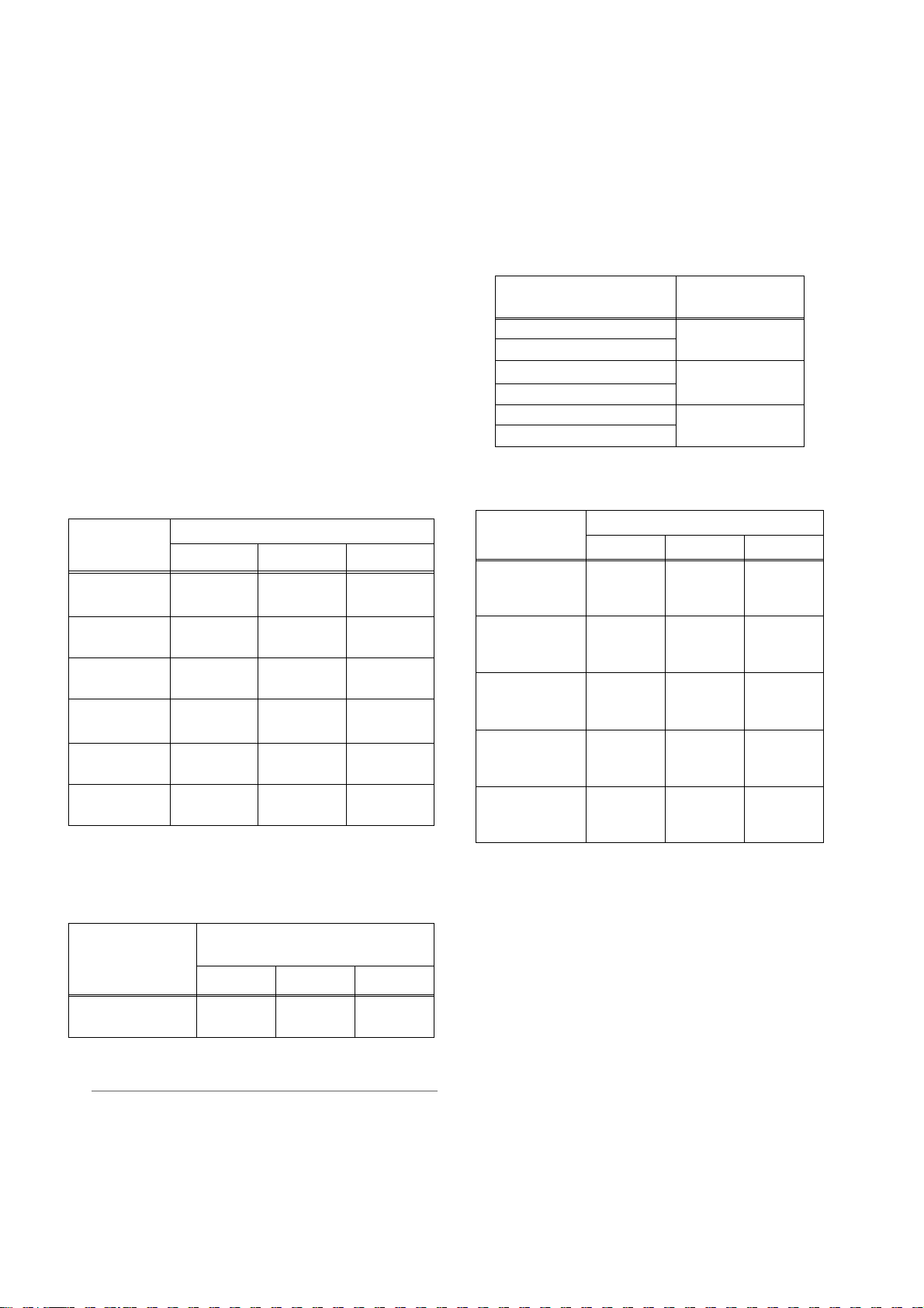
_ Multi-format
Mode SYSTEM MODE Recording method
1
AVC-Intra100*
AVC-Intra50*
1080-59.94i
DVCPRO HD
AVC-Intra100*
AVC-Intra50*
720-59.94P
HD
1080-50i
720-50P
480-59.94i
SD
576-50i
DVCPRO HD
AVC-Intra100*
AVC-Intra50*
DVCPRO HD
AVC-Intra100*
AVC-Intra50*
DVCPRO HD
DVCPRO50 59.94i
DVCP RO
DV
DVCP RO5 0
DVCP RO
DV
*1 When the AVC-Intra codec board (AJ-YBX200G) is installed
59.94i
29.97P (Native)
1
23.98P (Native)
59.94i
29.97P Over 59.94i
23.98P Over 59.94i (2-3 Pull-down)
23.98P Over 59.94i (2-3-3-2 Pull-down)
1
59.94P
29.97P (Native)
1
23.98P (Native)
59.94P
29.97P (Native)
29.97P Over 59.94P
23.98P (Native)
23.98P Over 59.94P (2-3 Pull-down)
1
50i
1
25P (Native)
50i
25P over 50i
1
50P
1
25P (Native)
50P
25P (Native)
25P Over 50P
29.97P Over 59.94i
23.98P Over 59.94i (2-3 Pull-down)
23.98P Over 59.94i (2-3-3-2 Pull-down)
50i
25P Over 50i
Features of Camera unit
_ 14-bit A/D conversion digital signal processing
Analog video signals are processed into digital data by a
14-bit A/D converter with sampling frequencies of 74
MHz. It is possible to reproduce images that are more
finely detailed.
_
Storage type high-sensitivity function (DS. GAIN)
The unit uses the storage type gain increase function by
driving the CCD progressively. With this function, it is
possible to obtain brighter pictures without increasing
noise under low light conditions.
This is a function that makes it possible to achieve
higher sensitivity of up to 20 dB above the regular gain
increase. Furthermore, this function can also be used as
picture effects.
_ Digital Zoom
The camera unit features progressive digital zoom. This
is particularly effective when you want to zoom-in closer
on the subject.
_ Auto White Balance with Automatic Tracking
capability
The white balance is automatically adjusted in real time,
according to the subject. This is effective for urgent
recording, where you can’t spare the time to make an
adjustment through the auto white balance feature.
_ DRS (Dynamic Range Stretcher) function
The dynamic range can be streched by compressing the
video signal level of a part with high brightness where
white-color-skipping phenomena occur during ordinary
shooting. (Refer to page 51)
_ Film-like Gamma function
The unit employs three types of film-like gamma to
easily obtain film tones accumulated through Varicam
(AJ-HDC27 series), so that a wide range of image
impressions can be reproduced for production. (Refer to
page 167)
_ Lens file function
The unit has 8 lens files.
By using an SD memory card, 64 lens files can be
stored. (Refer to page 92)
_ Focus assist function
The unit will display a marker to help with focusing when
shooting videos. This function provides a visual cue for
focusing. (Refer to page 51)
General:Features of Camera unit
8
Page 9

_ Data management function
Within the unit, one user data file and four sets of scene
file data can be saved.
By using an SD memory card as the setup card, up to eight
sets of setup data can be stored. (Refer to page 83)
Features of Recorder/player unit
_ Color bar
The unit employs the SMPTE color bar, ARIB color bar,
Split color bar for SNG (Satellite News Gathering) as
well as the conventional color bar, which is useful for
adjusting the color monitor. (Refer to page 175)
_ Multiple Slots
AJ-HPX2000 is equipped with five slots for P2 cards. Up
to five cards may be inserted in these slots for
continuous recording. They also provide new recording
capabilities specific to memory cards.
z
Hot-Swap recording
The Hot-Swap capability allows cards not in use to
be replaced without interrupting recording. This
facilitates continuous recording.
z Loop recording
AJ-HPX2000 can retain a certain amount of
previously recorded material by continuously looprecording data into a specified recording area.
z INTERVAL REC/ONE SHOT REC
The
AJ-HPX2000 features interval recording at
minimum one-frame intervals. This function is
particularly suited to shooting science and nature
programs. Frame-by-frame shooting is simple with the
one-shot recording function.
PRE-RECORDING function
z
In standby status, AJ-HPX2000 always stores video
and sound input to the camera for up to 8 seconds
(For 1080i/720P (HD)). This means that the PRERECORDING function, when turned on, records the
video and sound for a preceding duration preset by
the user. This feature recovers critical moments
that you might have missed. For DVCPRO and DV,
video and sound can be recorded for up to 15
seconds.
z Proxy recording (when AJ-YAX800G attached)
By installing the optional video encoder card (AJYAX800G), MPEG4 format video and real-time
metadata such as time code data can be recorded
simultaneously on the P2 card and the SD memory
card, together with the video and sound recorded by
the camera. This function is useful for confirmation
of editing of clips. For more information about the
approximate duration for proxy recording, see
[Approximate Proxy Recording Time (optional) on
SD memory cards (Except for 24P native mode)]
(page 10). Please also see <Cautions in using SD
memory cards>. (page 21)
z Data protection
Data on P2 cards will not be lost due to overwriting
unless the files are deleted or the cards are
initialised. Recordings are written only to free space.
_ 4-channel Digital Audio Recording (all formats)
In HD (1080i or 720P) mode, 4-channel digital audio
recording is used.
All formats in SD mode, DVCPRO, DV, and DVCPRO50,
also support 4-channel digital audio recording with highquality sound (48 kHz/16 bits).
_ Clip Thumbnailing
z Automatic generation of thumbnails
AJ-HPX2000 automatically generates a thumbnail for
each recording cut (clip). It is possible to make use of
this on the camera-recorder as well as for non-linear
editing purposes, and after uploading to a server.
z Thumbnail display on the LCD monitor
The 3.5-inch color LCD side of the your video
camera
of 12 clip thumbnails. You can choose a desired clip
to playback instantly.
z Seamless playback of selected clips
You can select more than one clip from the
thumbnail view for continuous playback and output
of seamless video.
recorder can provide a multi-screen view
Note
During continuous playback of clips in different
recording formats, seamless playback is not available.
z
Display of clip information
By selecting clips, information added to clips, such
as the recording time, Text Memo, Shot Marks and
metadata can be checked.
_ Text Memos & Shot Marks
Each clip can incorporate comments, in the form of text
memo added to the thumbnail associated with the time
code, together with shot marks which, for example, can
help you distinguish OK cuts from reject cuts.
Both text memos and shot marks can be added to
selected clips during and after a recording. This is
helpful for editing recorded video.
In addition, you can use the copy function for each text
memo block to take only the necessary portions out of a clip.
_ Front-mounted Sound Level Control Mechanism
AJ-HPX2000 features a front-mounted control for fine
adjustment of the sound recording level. This control is
particularly effective for adjusting the sound level when
you are shooting without a sound recordist. The control
can be disabled.
_ Support for Built-in Unislot Wireless Receive
AJ-HPX2000 is designed to support an optional slot-in
wireless receiver.
_ Recording Review Capability
This capability automatically plays back the last 2 to 10
seconds of recorded video, allowing you to quickly
check the recorded contents.
_ Built-in Time Code Generator/reader
A special-purpose Subcode track can be used to record
and reproduce time code information.
General
General:Features of Recorder/player unit
9
Page 10
_ Support for Metadata
AJ-HPX2000 is capable of recording positional
information (latitudes, longitudes and altitudes), as
UMID information (metadata), from the GPS unit AJGPS910G (optional accessory). Names/titles can also
be recorded, e.g. the camera person, the reporter, or the
program which was registered on the SD memory card
in advance. This information is also useful in managing
information on clips. Regarding SD memory cards,
please also see
<Cautions in using SD memory cards>
(page 21).
_ Recording Time
Operation of the following P2 cards with AJ-HPX2000
has been verified:
z
AJ-P2C004HG (4 GB)
z AJ-P2C008HG (8 GB)
z AJ-P2C016RG (16 GB)
(
The model numbers and capacities are accurate as of
August 2007 but may change to expand capacity.
)
The AJ-P2C002SG (2 GB) is disabled.
Recording Time on P2 Cards: When one 16 GB card is used;
HD Mode
Image system
1080-59.94i/
2
50i
*
1080-30PN/
25PN (Native)
1080-24PN
(Native)
720-59.94P/
2
50P
*
720-30PN/25PN
(Native)
720-24PN
(Native)
*1 When the AVC-Intra codec board (AJ-YBX200G) is
Recording method and Recording time
DVCPRO HD
Approx.
16 minutes
-
-
Approx.
16 minutes
Approx.
32 minutes
Approx.
40 minutes
AVC-Intra100
Approx.
16 minutes
Approx.
16 minutes
Approx.
20 minutes
Approx.
16 minutes
Approx.
32 minutes
Approx.
40 minutes
*1AVC -Intra5
Approx.
32 minutes
Approx.
32 minutes
Approx.
40 minutes
Approx.
32 minutes
Approx.
64 minutes
Approx.
80 minutes
1
0*
installed
*2 Including 30P, 24P, and 25P pull down of the DVCPRO
HD
SD Mode
Recording method and Recording
Image system
DVCPRO 5 0
Approx.
480-59.94i/576-50i
*3 For 2ch audio recording
*4 Including 30P, 24P, and 25P pull down
4
*
32 minutes
time
DVCPRO
Approx.
64 minutes
3
*
3
DV
*
Approx.
64 minutes
Notes
z The values for 8 GB P2 cards are 1/2 and the values
for 4 GB P2 cards are 1/4 those of 16 GB P2 cards
shown above.
z
If the one-time continuous recording exceeds the
duration which is given in the table below when a P2
card with a memory capacity of 8GB or more is used
in AJ-HPX2000, the recording is automatically
continued on a separate clip. When performing
thumbnail operations (such as display, delete, repair
or copy) for these kinds of clips using a P2 device, it
is possible to perform the operations for the entire
recording as a single clip. However, with nonlinear
editing software or a personal computer, the
recording may be displayed as separate clips.
Recording method (except
for native)
DVCPRO HD
AVC-Intra100*
AVC-Intra50*
DVC PRO 5 0
DVC PRO
DV
*1 When the AVC-Intra codec board (AJ-YBX200G) is installed
Approximate Proxy Recording Time (optional) on SD
memory card
Card No.
(Card Capacity)
RP-SDH256
(256 MB)
RP-SDH512
RP-SDK512
(512 MB)
RP-SDQ01G
RP-SDK01G
(1 GB)
RP-SDQ02G
RP-SDK02G
(2 GB)
RP-SDV024G
(SDHC 4 GB)
1
1
s (Except for 24P native mode)
MPEG4 recording rate
192 kbps 768 kbps 1500 kbps
Approx.
2 hour
17 minutes
Approx.
4 hour
27 minutes
Approx.
8 hour
56 minutes
Approx.
18 hour
11 minutes
Approx.
35 hour
42 minutes
Continuous
recording time
Approx.
5 minutes
Approx.
10 minutes
Approx.
20 minutes
Approx. 35
minutes
Approx. 69
minutes
Approx.
2 hour
19 minutes
Approx.
4 hour
44 minutes
Approx.
9 hour
18 minutes
Approx. 19
minutes
Approx. 38
minutes
Approx. 77
minutes
Approx.
2 hour
37 minutes
Approx.
5 hour
12 minutes
(Reference values when cards are used for continuous
recording with our products. Actual recording time depends
on the kind of scenes and the number of clips.
For SD or
SDHC memory cards with Class indications, the
recording time may be reduced significantly compared
with the actual capacity when images of short recording
time are recorded repeatedly.
)
The driver installed on the unit must be updated when
using SD memory cards other than as listed above. To
update the driver, refer to [Updating the firmware incorporated into the camera-recorder] (Page 189)
For the latest information on P2 cards and SD memory
cards not available in the operating Instructions, visit the
P2 Support Desk at the following Web sites.
https://eww.pavc.panasonic.co.jp/pro-av/
General:Features of Recorder/player unit
10
Page 11

Features of the Input/Output unit
_ Features USB2.0 port (HOST/DEVICE)
By connecting with a PC via USB2.0, a P2 card inserted
in AJ-HPX2000 can be used as a bulk storage device.
It is also possible to store data on a P2 card onto a USB
2.0-connected external hard disk equipped with USB
host capability as well as view clips stored on hard disks
and write them to P2 cards.
_ DVCPRO (IEEE1394) output and DV output
provided as a standard configuration
Data can be input/output to an external device through
the IEEE1394 digital interface. Use a 6-pin type
connector. The unit does not support the bus power.
While operating AVC-Intra, it is impossible to input/
output data with IEEE 1394.
_ HD/SD SDI output featured as standard
Video can be output as HD SDI signals, down-converted
SD SDI signals, or analog composite signals. SDI output
includes embedded audio etc.. (Refer to page 43) Note
that the SD mode does not output HD SDI signals.
_ Down converter output provided as a standard
configuration
In HD mode, the MON OUT output connector and the
VIDEO OUT connector (in setting VBS mode) output
down converter (analog composite) signals.
It is optimum for confirming shot images on the SD
monitor. (Refer to page 43)
_ HD/SD SDI input function (when the AJ-
YA350AG is attached)
The camera-recorder with the AJ-YA350AG extension
board attached can record SDI signals input through the
SDI input connector only if the signals are in the same
format as the camera-recorder.
_ Remote control connector
By connecting the remote control unit (AJ-RC10G),
which is available as an optional accessory, the unit can
be controlled remotely. (Refer to page 107)
_ Confirmation of return video signals
It is possible to confirm the return video signals (analog
HD-Y signals in the HD mode/VBS or Y signals in the
SD mode) supplied to the GENLOCK IN connector of
AJ-HPX2000 in the viewfinder to confirm programs.
(Only video signals from the same record format can be
confirmed.) (Refer to page 175)
_ DC OUT connector
The DC OUT connector of the unit produces 1.5 A of
electrical current.
By connecting an external switch to this connector, it is
possible to control REC start/stop.
Since a tally lamp can be used by connecting the LED
to this connector, it is useful for shooting video when
fixing the camera on a crane. (Refer to page 108)
General
Other features
_ Viewfinder connection
From the viewfinder connector of the unit, 1080-59.94i,
1080-50i, 480-59.94i or 576-50i signals are output.
Furthermore, signals are output for switching the
frequencies of the connected viewfinder.
Confirm images in multi formats by connecting the
viewfinder (AJ-HVF21G), which is available as an
optional accessory. (Refer to page 27)
While the AJ-VF20WBP (59.94 Hz)/E (50 Hz) can also
be connected, you cannot view video in formats with
different frequencies.
_ User button
On the side panel of the unit, three user buttons (USER
MAIN/USER1/USER2) are available.
Each button can be assigned the on/off function for any
frequently used feature selected from among the many
features of the unit, such as digital zooming and super
gain (Refer to page 51).
General:Features of the Input/Output unit
11
Page 12
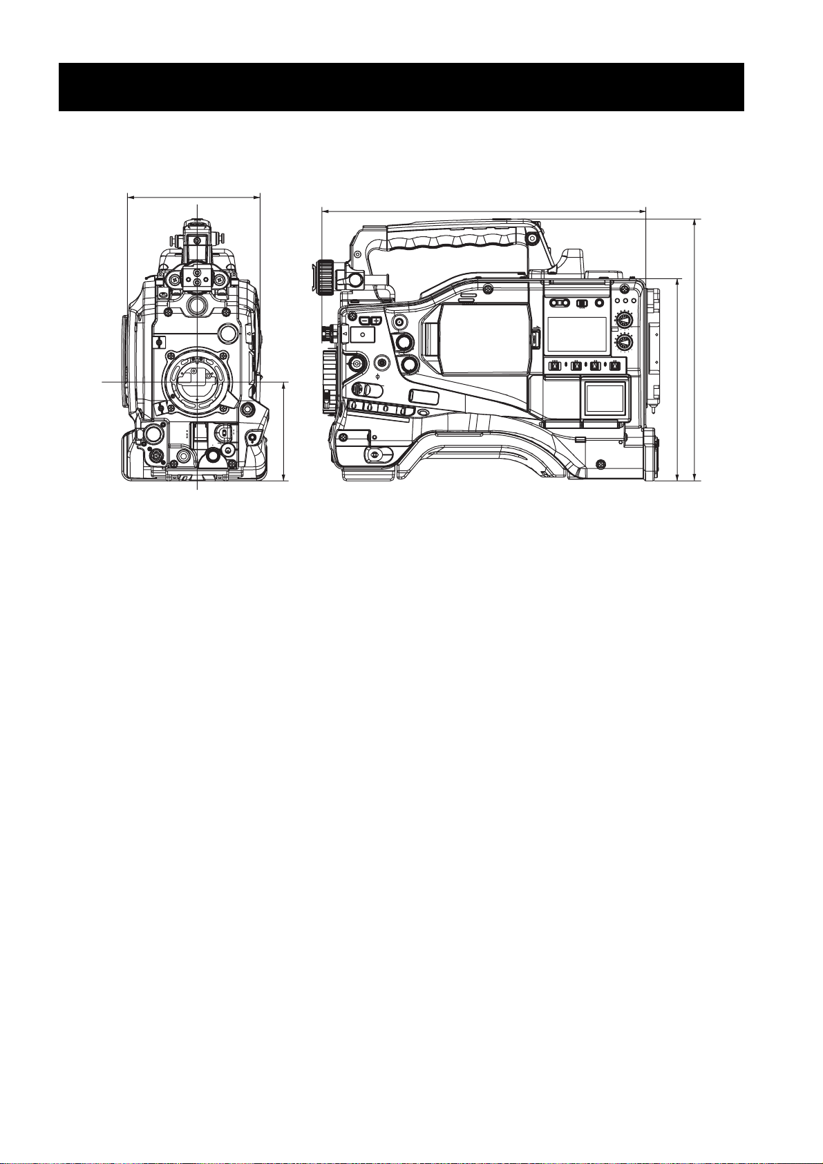
Unit: mm (inch)
3
137 (5- )
/
8
Dimensions drawing
1
318 (12- )
/
2
16
/
1
102 (4- )
8
/
5
4
/
1
270.5 (10- )
209 (8- )
General:Dimensions drawing
12
Page 13
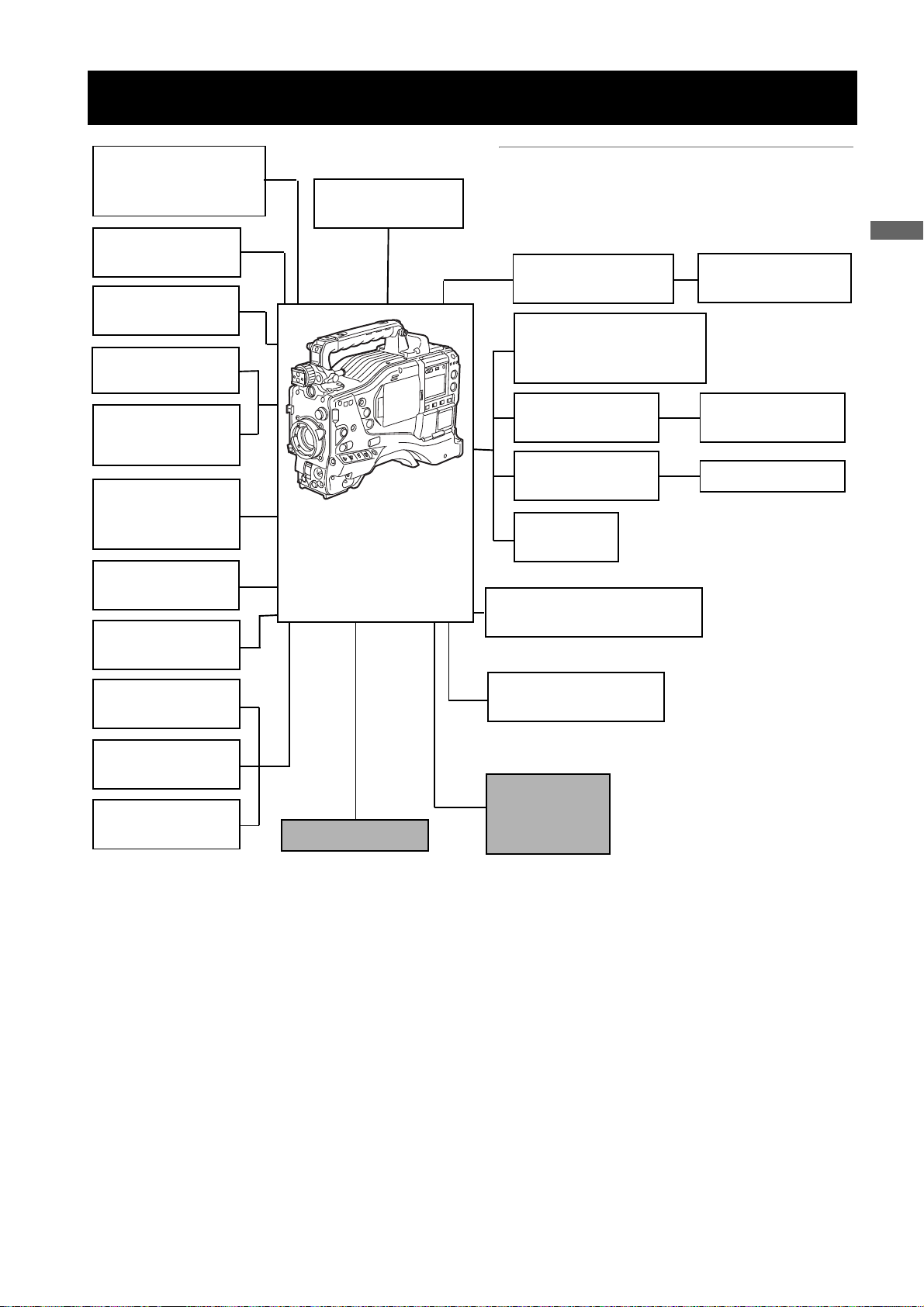
System Configuration
Unislot wireless
microphone receiver:
Sennheiser EK3041
Stereo microphone
AJ-MC900G
Microphone holder:
AJ-MH800G
2-type HD Viewfinder:
AJ-HVF21G
Viewfinder:
AJ-VF15B
AJ-VF20WB
Lens:
(Bayonet type)
Fujinon, Canon
GPS unit:
AJ-GPS910G
Tripod adapter:
SHAN-TM700
:
Video encoder card:
AJ-YAX800G
Memory Card
Camera-Recorder
AJ-HPX2000P
◆Note
All of the devices and accessories other than the unit,
which are shown in this system configuration, are optionally available. To use these devices and accessories, refer
to the respective operation manuals.
Remote control cable:
AJ-C10050G
DIONIC90/160
HYTRON50/100/140
PROPAC14, TRIMPAC14
V mount type
Battery plate
NP-1 type
Battery case
External DC
power supply
AVC-Intra codec board:
AJ-YBX200G
Remote control unit:
AJ-RC10G
ENDURA7/10
BP-GL65/95
NP-L7
General
Rain cover:
SHAN-RC700
Soft carrying case:
AJ-SC900
Hard carrying case:
AJ-HT901G
* For the latest information on P2 cards and SD memory cards not available in the operating Instructions, visit the P2
Support Desk at the following Web sites.
https://eww.pavc.panasonic.co.jp/pro-av/
SD Memory cards*
HD/SD SDI input board:
AJ-YA350AG
P2 Cards*:
AJ-P2C004HG
AJ-P2C008HG
AJ-P2C016RG
General:System Configuration
13
Page 14
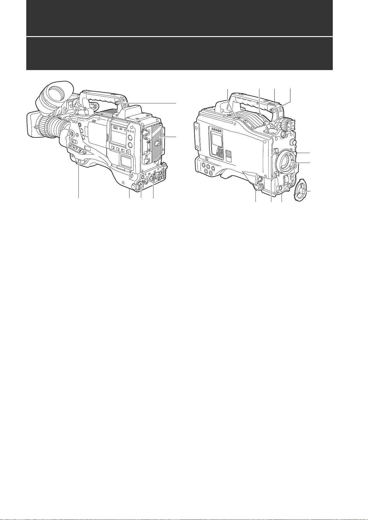
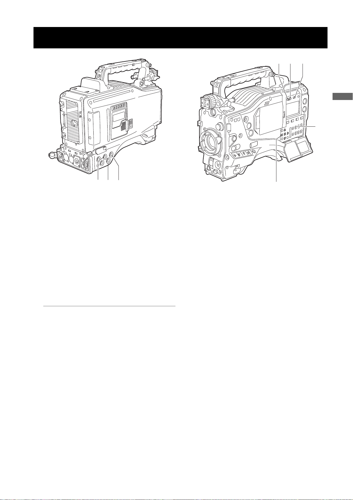
Parts and their Functions
Power Supply and Accessory Mounting Section
1
34
15
1. POWER switch
Used to turn on/off the power.
2. Battery mount
A battery pack from Anton/Bauer is mounted here.
3. DC IN (external power input) socket (XLR, 4P)
camera-recorder is connected to an external DC
power supply.
5
12
7
13
11
6
2
14
10.Lens mount cap
To remove the cap, raise the 9. lens lever.
When the lens is not mounted, replace the cap.
11.Light cable clamp
Secures the light cable.
12.Lens cable/microphone cable clamp
This clamp secures the lens and microphone cables.
6
9
8
10
4. BREAKER switch
When an excessive amount of current is fed through
the camera-recorder, due to any abnormal event, the
breaker automatically turns off the power in order to
protect the device.
After the interior of the camera-recorder has been
checked and/or repaired, this button must be
depressed. If there is no unusual reaction, the unit can
be powered-up.
5. GPS connector
This connects the optional GPS unit AJ-GPS910G.
6. Shoulder strap fittings
The shoulder strap is attached here.
7. Light shoe
A video light or similar accessory can be attached
here.
8. Lens mount (bayonet 2/3-type)
The lens is attached here.
9. Lens lever
Lower this lever to lock the lens to the lens mount.
13.Tripod mount
When you want to mount camera-recorder on a tripod,
the optional tripod adapter (SHAN-TM700) is attached
here.
14.LENS jack (12-pin)
The lens connection cord is connected here. For a
detailed description of your lens, see the relevant
manufacturer’s instruction manual.
15.DC OUT (DC power supply) output socket
This output socket is designed for 12-VDC. It provides
a maximum current of 1.5 A.
Connect an external switch to this socket to control
REC starts and stops or an LED for use as a tally
lamp. For more information, see [
external switch
] (page 108).
Connection of the
Parts and their Functions:Power Supply and Accessory Mounting Section
14
Page 15
Audio (input) Function Section
12
11
14 10
13
3
7
Parts and their Functions
2
6
1
1. MIC IN (microphone input) jack (XLR, 5-pin)
A microphone (optional accessory) is connected here.
Power for the microphone comes from this jack.
A remote microphone may be connected. When a
microphone is used, set the power to ON through the
menu option FRONT MIC POWER.
These options are found in the <MIC/AUDIO2> screen
on the MAIN OPERATION page.
2. AUDIO LEVEL CH1/CH2 (audio channel 1 & 2
recording level adjustment) controls
With the 3. AUDIO SELECT CH1/CH2 switch
positioned to [MAN], these controls can be used to
adjust the recording levels for Audio Channels 1/2.
Note that the controls are designed to be locked. For
adjustment, each control must be depressed while
turning.
3. AUDIO SELECT CH1/CH2 (audio channel 1 &
2 automatic/manual level adjustment
selector) switch
Use this switch to select recording level control mode
for Audio Channels 1 and 2.
AUTO: Recording level automatically controlled.
MAN: Recording level manually controlled.
4. AUDIO IN (audio input selector) switch
Use this switch to select the signals recorded through
Audio Channels 1 - 4.
FRONT: Signal from the microphone connected to the
1. MIC IN jack is recorded.
W.L. (WIRELESS) :
Signal from the slot-in wireless receiver is
recorded.
REAR: Signal from the audio device connected to
the 5. AUDIO IN CH1/CH2 connector is
recorded.
815
4
5
9
Note
When you use stereo microphone (AJ-MC900G
optional), set both CH1 and CH2 to [FRONT]. The
signal from L CH is recorded to CH1 and that from R
CH to CH2.
5. AUDIO IN CH1/CH2 (audio input channel 1 &
2) connectors (XLR, 3-pin)
Audio devices or a microphone may be connected
here.
6.
LINE/MIC/+48V (line input/mic input/mic input +
48V) selector switch
Used to select the audio signal input from the 5.
AUDIO IN CH1/CH2 connectors.
LINE: Audio signal line-input from the audio device is
input.
MIC: Audio signal from a self-powered (active)
microphone is input. (The main unit does not
supply power to the remote microphone).
+ 48V:Audio signal from a passive microphone is
input. (The unit supplies power to the remote
microphone).
7. Wireless slot
A Unislot wireless receiver (optional accessory) may
be attached here.
8. FRONT AUDIO LEVEL (audio recording level
adjustment) control
This control adjusts the recording levels for Audio
Channels 1 and 2.
However, when the 3. AUDIO SELECT CH1/CH2
switch is set to “AUTO”, the level will adjust
automatically and the 2. AUDIO LEVEL CH1/CH2
knob and this knob will not be active.
The control can be enabled or disabled through the
menu options FRONT VR CH1 or FRONT VR CH2.
These options can be found in the <MIC/AUDIO1>
screen on the MAIN OPERATION page.
Parts and their Functions:Audio (input) Function Section
15
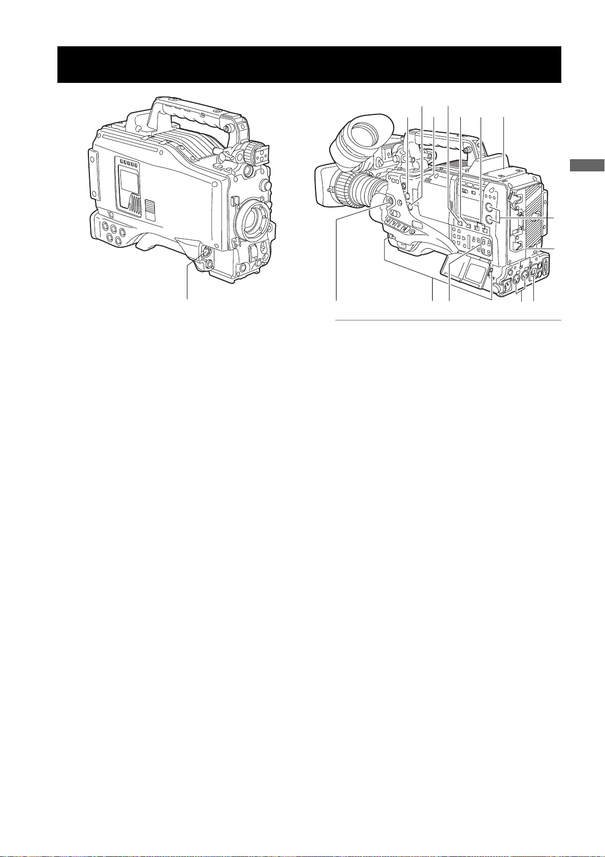
Page 16

Audio (output) Function Section
9. AUDIO OUT connector (XLR, 5-pin)
This connector outputs audio signals recorded on
Channels 1/2 or 3/4.
Output signals are selected with the MONITOR
SELECT CH1/2 / CH3/4 selector switch.
10.MONITOR SELECT (audio channel) CH1/2 /
CH3/4 selector switch
Use this switch to select the audio channel whose
signals are output to the speakers, earphones or
AUDIO OUT connector.
CH1/2: Signals on Audio Channels 1 and 2 are output.
CH3/4: Signals on Audio Channels 3 and 4 are output.
The channel indications on the display window and on
the audio level meter in the viewfinder are
synchronised with this selector switch.
11.MONITOR SELECT (audio selection) CH1/3 /
ST / CH2/4 selector switch
The MONITOR SELECT switch is synchronised with
the audio signal output to the speakers and
earphones, and from the AUDIO OUT connector.
CH1/3: Signal on Audio Channel 1 or 3 is output.
ST: Stereo audio signals on Audio Channels 1
and 2 or Audio Channels 3 or 4 are output.
The stereo signals can be changed to mixed
signals using a menu option.
CH2/4: Signal on Audio Channel 2 or 4 is output.
14.Speakers
The speakers output EE sound during recording, and
reproduced sound during playback.
The speakers emit an alarm sound when the warning
lamp blinks and/or the indicator activates.
When the 15. PHONES jack is connected with
earphones, sound from the speaker is automatically
muted.
15.PHONES (earphones) jack (mini jack)
This connector is designed for audio monitoring
(stereo) earphones. When earphones are connected,
sound from the speakers is automatically muted.
Both the front and rear connectors output the same
sound.
Monitor
switch
CH1/3 Audio Channel 1 Audio Channel 3
ST
CH2/4 Audio Channel 2 Audio Channel 4
* You can select between stereo and mixed signal types
using the menu option MONITOR SELECT. This menu
option can be found in the <MIC/AUDIO2> screen on the
MAIN OPERATION page.
Stereo signals from
Audio Channels 1 and 2*
MONITOR SELECT switch
CH1/2 CH3/4
Stereo signals from
Audio Channels 3 and 4*
12.MONITOR (volume) control
Used to control the volume of sound output from the
monitor speakers and earphones.
13.ALARM (warning alarm volume adjustment)
Used to control the volume of the warning sound
emitted from 14. speakers or earphones connected to
the 15. PHONES jack.
If the control is minimised, no alarm is audible.
Parts and their Functions:Audio (output) Function Section
16
Page 17
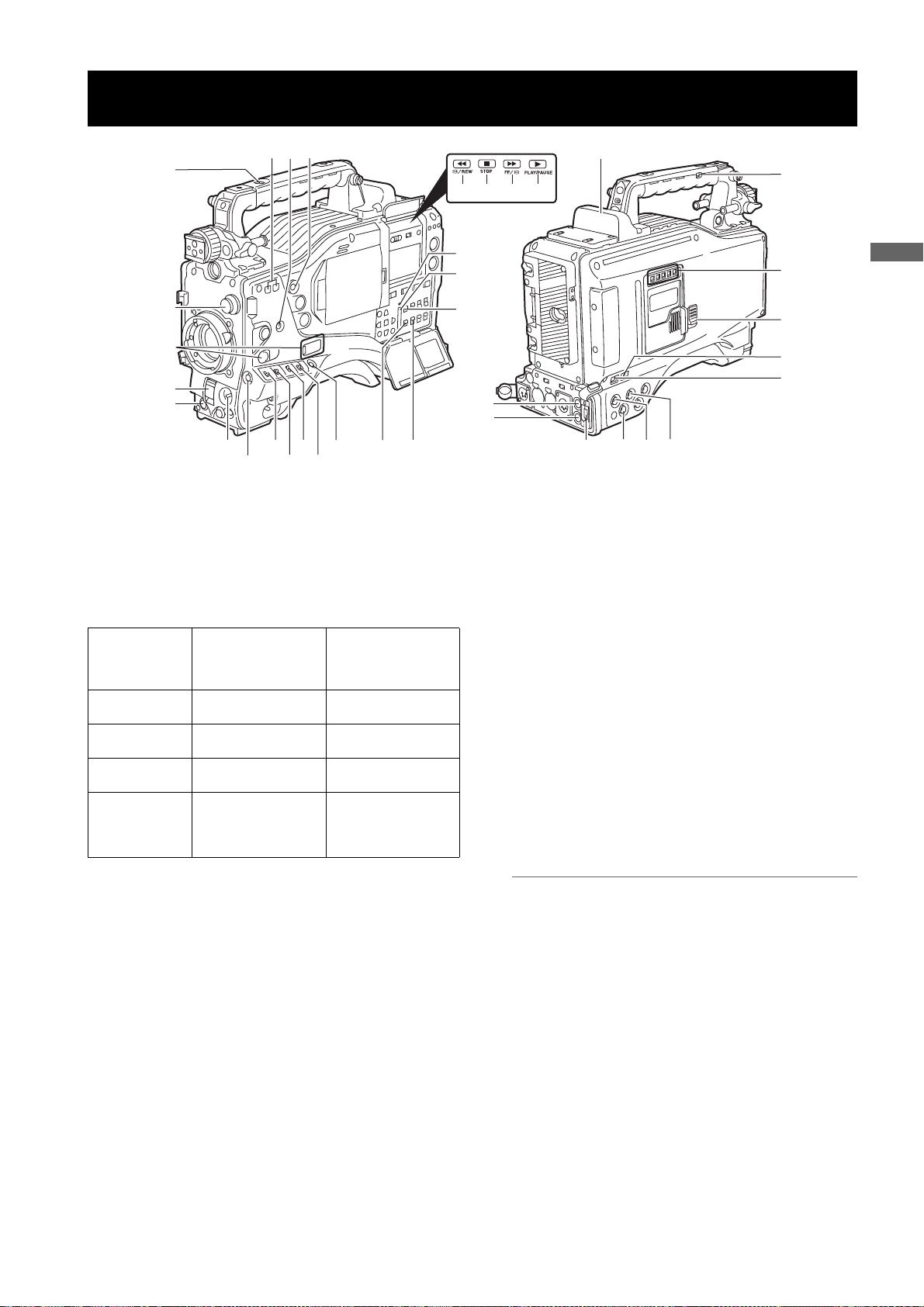
Shooting and Recording/Playback Functions Section
9
24
10
8
21
22
20
36
35
23
34
25
26
Parts and their Functions
1
2
3
11
19
4
12
14
6
5
7
13
16
1. CC/ND FILTER (filter selector) control
Used to select a filter appropriate for illumination and
color temperature of the subject.
When the menu option DISP MODE is set to “3”,
switching this control displays the selected filter
number in the viewfinder.
Examples of filter selection according to shooting conditions
Setting of the
CC/ND FILTER
control
1 3200K
2 5600K + 1/8
3 5600K
4 5600K + 1/64
Description of
filter
Shooting
conditions
Sunrise, sunset
Studio
Clear outdoor
environments
Cloudy/rainy outdoor
environments
Clear, bright scenes
such as snowscape,
high mountains,
beaches, etc.
15
17
33
18
32
31
30
3. SHUTTER switch
Used to enable or disable the electronic shutter.
OFF: Electronic shutter disabled.
ON: Electronic shutter enabled.
SEL: Used to change the speed of the electronic
shutter.
This dial switch returns to its original position. Each
turn of the switch alters the shutter speed.
For more information, see [
Shutter
] (page 49).
Setting the Electronic
4. AUTO W/B (white/black) BAL switch
AWB : White balance is automatically adjusted.
When the WHITE BAL switch on the side is
positioned at [A] or [B], the adjusted value is
stored in the memory.
Note that when the switch is positioned at
PRST this function does not work.
ABB: Back balance is automatically adjusted.
27
28
29
2. USER MAIN, USER 1 and USER 2 buttons
These buttons can be assigned user-selected
functions, using a menu option. Each button, when
pressed, performs the assigned function.
For more information, see [
USER MAIN, USER1 and USER2 Buttons
Assigning Functions to
] (page 51).
Parts and their Functions:Shooting and Recording/Playback Functions Section
Note
To stop automatic adjustment of the white or black
balance in progress, set the switch to either ([AWB] or
[ABB]).
If automatic adjustment is cancelled, the value in effect
before automatic adjustment will be used.
17
Page 18

5. Gain selector switch
Use this switch to select video amplifier gain,
according to lighting conditions under which you are
shooting.
The values for L, M, and H can be preset using menu
options.
These are factory-set to 0 dB for L, 6 dB for M, and 12
dB for H.
6. OUTPUT/AUTO KNEE selector switch
Used to select the video signals sent from the camera
unit to the memory, viewfinder and video monitor.
CAM. AUTO KNEE ON:
Video being recorded through the camera is sent
with the auto knee circuit activated.
It is also possible to assign the DRS (Dynamic Range
Stretcher) function instead of the AUTO KNEE
function.
CAM. AUTO KNEE OFF:
Video being recorded through the camera is sent in
manual knee mode.
BARS:
Color bar signal is output. The auto knee circuit does
not work.
You can select between four types of color bar signal.
For more information, see [
Auto Knee function
Usually, when you adjust levels to shoot people or scenery
against a strongly lit background, the background will be totally
whited-out, with buildings and other objects blurred. In this case,
the auto knee function reproduces the background clearly. This
function is effective when:
•The subject is a person positioned in the shade under a clear
sky.
•The subject is a person inside a car or building, and you also
want to capture the background visible through a window.
•The subject is a high-contrast scene.
SW MODE] (page 175).
8. MODE CHECK button
Each press of this button changes the screen type in
the viewfinder in the following order: STATUS, !LED,
FUNCTION, AUDIO.
This does not affect the signal output from the camera.
9. MARKER SELECT button
This button selects the marker information indicated
on the viewfinder screen. It switches between two
marker information indications, which can be selected
using a menu option. Pressing this button once
switches the indicated marker information from A
(Marker A) to B (Marker B), and pressing again
switches B to OFF (no marker). When the power is
turned on, the last selected indication before powerdown appears.
For more information, see [
Displays (MARKER SELECT button function)
79).
Marker Check Screen
10.SYNCHRO SCAN ADJUSTMENT buttons
These buttons are enabled when the 3. shutter switch
is positioned at [ON] and synchro scan is selected.
They are used to adjust the speed of the synchro
scan.
The – button decreases shutter speed; the + button
increases shutter speed.
If you shoot a PC monitor, for example, you should
adjust shutter speed so that the horizontal bars in the
viewfinder will produce less noise.
11.REC START/STOP button
Pressing this button starts recording, pressing again
stops recording.
This button has the same function as the 24. REC
button on the handle and the VTR button at the lens.
] (page
7. WHITE BAL (white balance memory selector)
switch
Used to select the white balance adjustment method.
PRST: Use this when you have no time to adjust the
white balance.
The value for the white balance is factory-set
to 3200 K.
It can be changed to any color temperature
using a menu option. For more information,
Setting Color Temperature Manually]
see [
(page 47).
A or B: Pressing the 4. AUTO W/B BAL Switch
toward [AWB] automatically adjusts the white
balance, saving the adjusted value in
Memory A or B. For more information, see
Adjusting the White Balance] (page 45).
[
Through a menu option, the auto-tracking white
balance (ATW) can be assigned to B.
For more information, see [
Balance
] (page 45).
Adjusting the White
12.SHOT MARK/Menu cancel button
Pressing this button while recording adds a shot mark
to the thumbnail of that clip. This button also adds a
shot mark to any thumbnail selected on the LCD
monitor.
For more information on shot marks, see [
Function
This button cancels the revised set value when the
menu is displayed.
] (page 41).
Shot Mark
13.Text memo button
Records a text memo if pressed during recording or
playback or when playback is paused.
Parts and their Functions:Shooting and Recording/Playback Functions Section
18
Page 19

24
10
9
8
21
22
20
36
35
23
34
25
26
1
2
3
11
19
4
12
14
6
5
7
13
16
14.SAVE ON/OFF switch
Used to select the power supply method for each
output section.
ON: The output selected through the menu option
SAVE SW is power-saved. This option can be
found on the OPTION MODE screen on the
SYSTEM SETTING page.
OFF: Power saving is canceled.
Note
The ON/OFF switch does not function during recording. The ON/OFF status changes after recording is
completed.
15.VIDEO OUT (output signal selector) switch
Changes the mode of the signals output through the
VIDEO OUT connector.
HD SDI : HD SDI signals are output. When the
camera-recorder is in SD mode, SD SDI
signals are output.
SD SDI : SD SDI signals are output. (Signals are
down-converted in HD mode.)
: Composite video signals are output. (Signals
VBS
are down-converted in HD mode.)
16.VIDEO OUT CHARACTER switch
This switch controls the superimposition of characters
onto the video output from the VIDEO OUT connector.
ON: Characters are superimposed.
OFF: Characters are not superimposed.
For types of characters, see [
from VIDEO OUT connector
Settings of signals output
] (page 81).
17.VIDEO OUT (video signal output) connector
This connector outputs video signals. The video
signals linked to the settings of 15. VIDEO OUT
switch, 16. VIDEO OUT CHARACTOR switch and
19.OUTPUT SEL switch are output from here.
15
17
33
32
18
31
30
27
28
29
18.MON OUT (monitor output) connector
Used to output down-converted (analog composite)
signals for the monitor. The video signals linked to the
setting of the OUTPUT SEL switch are output from
here. Through an internal menu option, the characters
can be superimposed independently of the VIDEO
OUT connector. For more information, see [
signals output from MON OUT connector
] (page 82).
19.OUTPUT SEL (output signal selection) switch
Used to switch the signals output from the VIDEO
OUT and MON OUT connectors.
MEM: Video from the camera is output during
recording or when recording is paused or
playback signals are output from the P2 card
during playback.
CAM: Video from the camera is output constantly.
OFF: Video is not output, and the camera-recorder
operates in power-saving mode.
Note that the audio output is synchronised with the
video.
For types of video outputs, see [
output from VIDEO OUT connector
[
Settings of signals output from MON OUT connector]
(page 82).
Notes
z During recording, this switch does not switch output
signals before stopping the recording operation.
z When CAM is not selected through the REC
SIGNAL menu option, the output signals are the
same as for MEM even if the switch is set to CAM.
The menu option REC SIGNAL is found in the
SYSTEM MODE screen on the SYSTEM SETTING
page.
Settings of signals
] (page 81) or
Parts and their Functions
Settings of
Parts and their Functions:Shooting and Recording/Playback Functions Section
19
Page 20

20.REW (rewind) button and lamp
During pause, this button performs a fast-reverse
playback with the lamp blinking.
During playback, it performs an approximately 4
reverse playback with the PLAY and REW lamps
blinking.
If this button is pressed when playback is paused, the
start of the clip being played back is located in pause
mode.
21.STOP button
This button stops playback.
22.FF (fast forward) button and lamp
During pause, this button is used to perform fast
playback with the lamp blinking.
During playback, it performs an approximately 4
playback with the PLAY and FF lamps blinking.
If this button is pressed when playback is paused, the
start of the next clip is located in pause mode.
23.PLAY/PAUSE button
This button is used to view playback using the
viewfinder screen or a color video monitor. The lamp
comes on when playback starts.
In playback mode, this button pauses (PLAY/PAUSE)
playback with the lamp blinking.
a fast-
a fast
30.GENLOCK IN connector
Used to input an HD Y signal when GENLOCKing the
camera or externally locking the time code.
Alternatively, a composite signal can be input as the
reference signal. Note that the subcarriers for the
down-converter (composite signal) output from the
camera-recorder cannot be externally locked.
Notes
z When HD Y signal is input and RET is selected, you
can check return video on the viewfinder screen.
The menu option RET SW can be found in the SW
MODE screen on the CAM OPERATION page.
z When the mode is set to SD, you can record original
signals by specifying VIDEO for the menu option
REC SIGNAL.
31.HD/SD SDI IN input connector
If installed, the optionally available HD/SD SDI input
board (AJ-YA350AG) acts as an input connector for
HD/SD SDI signals. You can record signals from this
input connector by specifying SDI for the menu option
REC SIGNAL. For details, refer to [Connection using
the SDI IN connector (when AJ-YA350AG attached)]
(page 137).
24.REC button
Pressing this button starts recording, and pressing
again stops recording.
This button has the same function as 11. the REC
START/STOP button and the VTR button at the lens.
It may be disabled with 25. the recording protection
button.
25.REC protection button
This button disables 24. the REC button on the handle.
ON: The REC button is enabled.
OFF: The REC button is disabled.
26.P2 CARD ACCESS LED
This LED indicates the recording and playback status
of each card.
27.Slide lock button
Used to open the slide-out door for inserting P2 cards.
While depressing this button, slide the door to the left.
28.USB 2.0 connector (DEVICE)
29.USB 2.0 connector (HOST)
A USB 2.0 cable is connected here.
When the menu option PC MODE is set to “ON”, data
can be transferred via USB 2.0. During such data
transfer, recording, playback or operations of clips is
permitted.
The menu option PC MODE is found in the SYSTEM
MODE screen on the SYSTEM SETTING page. For
more information, see [Connection with external
devices using the USB 2.0 port] (page 131).
Parts and their Functions:Shooting and Recording/Playback Functions Section
20
Page 21
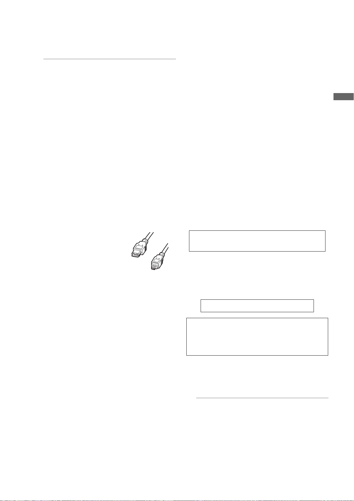
32.DVCPRO/DV connector
This is an in/output connector for video, voice, and
data that comply with the IEEE1394 standard.
Notes
z Power is not supplied from the unit.
z Be absolutely sure to bear the following points in
mind when connecting the IEEE1394 cable (DV
cable).
Ensure that the connections with other devices are
made on a 1:1 basis.
When a DV cable has been connected to the DV
connector, do not apply any strong external force
as this may damage the connector.
When error code 1394 E-92 (1394 INITIAL
ERROR) appears, disconnect the connecting
cables and re-connect them or turn off the
camera-recorder’s power and turn it back on.
Ensure that the unit and all of the connected
devices are each grounded (or connected to a
common ground) before use.
If it is not possible to ground the unit and devices,
turn off the power of the unit and of all the
connected devices before connecting or
disconnecting the IEEE1394 cable.
When the unit is to be connected to a device
equipped with a 4-pin type of connector, connect
the unit’s connector (6-pin type) first.
When connecting the unit
with a PC equipped with
a 6-pin type ofconnector,
connect the 1394 cable
as dictated by the shapes
of the 1394 connectors.
Bear in mind that
inserting a plug the wrong way round may damage
the unit.
When the unit is used in AVC-Intra format, image/
voice signals cannot be output/input through the
DVCPRO/DV connector.
6-pin type
4-pin type
33.REMOTE (remote control) connector
The remote control unit AJ-RC10G (optional
accessory) is connected here.
34.OPTION SLOT
Attach the video encoder card (AJ-YAX800G,
optional). For information about the installation and
proxy recording, see the AJ-YAX800G instruction
manual.
35.SD memory card insertion slot
An SD memory card (optional accessory) is inserted
here.
SD memory cards are used for recording and
accessing the menu settings of cameras and the lens
files, uploading metadata, and proxy recording
(optional).
<Cautions in using SD memory cards>
Use the unit by inserting an SD memory card that is
compliant with the SD standard or the SDHC standard.
MultiMediaCards cannot be used. (Bear in mind that
taking pictures may no longer be possible if you do use
them.)
If you intend to use miniSD cards in camera-recorder,
always install the adapter specially designed for
miniSD cards. (The unit will not work properly if only
the miniSD card adapter is installed. Make sure that
the card has been installed in the adapter before using
it.)
Use of Panasonic’s SD memory cards and miniSD
cards is recommended. Be sure to format cards using
camera-recorder.
To format SD memory cards using a personal
computer, download the dedicated software from the
support site.
Any SD memory card with the following capacities (8
MB to 2 GB) and any 4 GB SDHC memory card can
be used with the unit.
8 MB 16 MB 32 MB 64 MB
128 MB 256 MB 512 MB 1 GB
2 GB 4 GB (SDHC)
To record proxy (optional), use an SD memory card with
a capacity of 256 MB, 512 MB, 1 GB, or 2 GB labeled
“High Speed” or use a 4 GB SDHC memory card.
For the latest information not available in the operating
Instructions, visit the P2 Support Desk at the following
Web sites.
https://eww.pavc.panasonic.co.jp/pro-av/
z The SDHC card conforms to a new standard for memory
cards with a large capacity of more than 2 GB which was
established by the SD Association in 2006.
z The SD card logo is a registered trademark.
z MMC (MultiMediaCard) is a registered trademark of Infineon
Technologies AG.
36.BUSY (operation mode display) lamp
This lamp indicates the active status of the SD
memory card.
It stays illuminated when the card is active.
Parts and their Functions
Note
While the lamp is on, do not insert or remove the card.
Parts and their Functions:Shooting and Recording/Playback Functions Section
21
Page 22

Menu Operation Section
1. MENU button
Used to turn on/off the menu.
2. JOG dial button
With the menu open, this button is used to navigate
through menu pages, select options and specify
values.
For directions on manipulating the menu, see [Menu
4
3
5
Configuration] (page 151).
3. SD memory card insertion slot
An SD memory card (optional accessory) is inserted
here. It is used when writing or saving menu data or
lens files on an SD memory card.
2
1
4. BUSY (operation mode display) lamp
This lamp indicates the active status of the SD
memory card.
It stays illuminated when the card is active.
Note
While the lamp is on, do not insert or remove the card.
5. Shot Mark/Cancel Menu button
Undoes any changes to the menu option settings if
pressed during the changes
Parts and their Functions:Menu Operation Section
22
Page 23
Time Code Section
6
5
4
Parts and their Functions
7
13
2
1. GENLOCK IN connector (BNC)
This connector is used to input a reference signal
before the camera unit is gen-locked, or before the
time code is externally locked.
2. TC IN connector (BNC)
This connector is used to input a reference time code
when you externally lock the time code.
3. TC OUT connector (BNC)
When you inter-lock the time code of camera-recorder
with that of an external device this must be connected
with the time code input (TC IN) connector of the
external device.
Note
The time code must be input in the same format as the
system mode of the camera-recorder.
4. HOLD button
Pressing this button freezes the time data indication
on the counter. Note that time code generation
continues. Pressing the button again reactivates the
counter.
This function is used to ascertain the time code or CTL
count of a particular recorded scene.
8
6. DISPLAY (counter display selector) switch
Indications of the time code, CTL and user bits on the
counter of the display window depend on the positions
of this switch and the 7.TCG switch.
Pressing the 4.HOLD button also displays Date/Time/
Time Zone.
UB: User bits, TIME, DATE or Time zone indicated.
TC: Time code indicated.
CTL: CTL indicated.
7. TCG (time code selector) switch
This switch is used to specify the stepping mode for
the built-in time code generator.
F-RUN: Select this position to continuously advance
the time code independently of the P2 card
recording status.
Use this mode to synchronise the time code
with the time of day, or to externally lock the
time code.
SET: Select this position to set the time code and/
or user bits.
R-RUN: Select this position to advance the time code
only during recording.
For spliced scenes recorded on P2 cards,
the sequence of time codes is unbroken.
5. RESET button
This button resets the time data (CTL) on the counter
to “00:00:00:00”.
If this button is pressed when with the 7.TCG switch
positioned at [SET], time code and user bits data are
reset to 0, and real-time data is reset to the initial
value.
8. CURSOR and SET buttons
Use these buttons to set the time code and user bits.
The four triangular buttons are the CURSOR buttons,
and the center rectangular one is the SET button.
For guidance in setting the time code and user bits,
see [
Setting Time Data] (page 55).
Parts and their Functions:Time Code Section
23
Page 24

Warning and Status Display Functions
1
2
6
7
1. Back tally lamp
When the 2.BACK TALLY switch is set to [ON], the
lamp behaves in the same way as the front tally lamp
at the viewfinder.
3
4
5
8
7. Display window
This window displays warnings, battery-remaining
level, sound volume, time data, and other information.
Note
When the battery is installed, the camera-recorder
indicates the data even if the power is turned off. To
turn off the data indications to keep the battery from
being discharged, specify OFF for the menu option P.
OFF LCD DISPLAY found in the TC/UB screen on the
MAIN OPERATION page.
8. Rear tally lamp
When the 2.BACK TALLY switch is set on [ON], the
rear tally lamp behaves in the same way as the back
tally lamp.
2. BACK TALLY switch
This switch controls the action of the 1.back and 8.rear
tally lamps.
ON: Back and rear tally lamps enabled.
OFF: Back and rear tally lamps disabled.
3. WARNING lamp
This lamp starts blinking or lights up if something
unusual occurs in the memory.
4. USB lamp
Stays on when the camera-recorder is in USB mode.
5. Access lamp
Blinks when the camera-recorder is in recording or
playback mode or when a P2 card is being accessed,
or stays on when a recordable P2 card is inserted.
6. LIGHT button
Use this button to control illumination of the display
window.
Alternately pressing this button toggles illumination of
the 7.display window on or off.
Parts and their Functions:Warning and Status Display Functions
24
Page 25
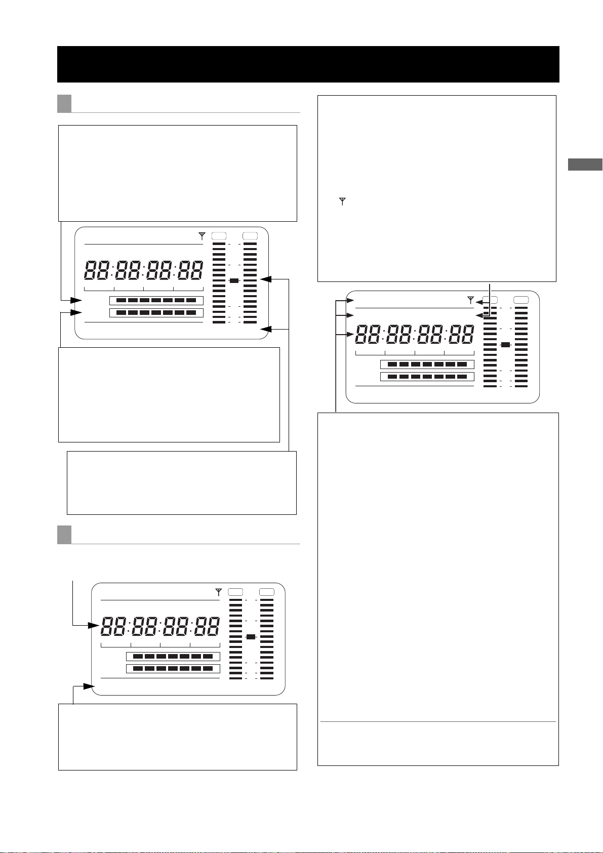
Display Window Functions
P2 card/battery-remaining level indications
Media-remaining space indication bar
The bar indicates the remaining free space on each P2 card,
using a seven-segment display.
Each segment can represent either three or five minutes of
remaining free space, depending on the value set through the
menu option CARD REMAIN/
segments disappear one-by-one. The menu option CARD
REMAIN /
on the MAIN OPERATION page.
can be found in the <BATTERY/P2CARD> screen
SLAVE HOLD W GPS
NDF
VTCG
CTL
h
MEDIA
BATT
TIME DATE
Y minM
E
EF
LOOP
Battery-remaining level indication bar
For a battery with a digital indicator (percentage indication), if the
remaining level of the battery is higher than 70%, all seven
segments up to the “F” position are lit.
When the remaining level falls below 70%, the segments go out
one-by-one for each drop of 10%. All seven segments can be set
to light up when the battery-remaining balance is 100%. To do so
select “100%” for the menu option BATT REMAIN FULL in the
<BATTERY/P2CARD> screen of the MAIN OPERATION page.
Audio channel level meter
When the MONITOR SELECT CH1/2 / CH3/4 switch is set to
[CH1/2], the meter indicates 1 and 2 as the audio channel
numbers, together with their audio levels. When the switch is
set to [CH3/4], the meter indicates 3 and 4 as the audio
channel numbers, together with their audio levels.
. According to the set value, the
HDV
OVER OVER
0
P-iREC
10
s
frm
D
OP-SLOT
F
18
30
40
OO
-dB
13 24
Memory action status indication
Error Code Indication (for more information, see
[Warning System] (page 145))
frm
OVER OVER
F
13 24
Loop Recording
OO
-dB
0
10
18
30
40
SLAVE HOLD W GPS
NDF
VTCG
CTL
h
MEDIA
BATT
TIME DATE
Y minM
E
EF
LOOP
Information indication
LOOP:
OP-SLOT: Remains illuminated when a video encoder card is
Stays illuminated in LOOP REC mode. For information
about the LOOP REC mode, see [
(page 36).
operated in the optional slot.
HDV
P-iREC
s
D
OP-SLOT
Mode indication
W: Stays illuminated when the camera-recorder operates
in SD mode (480-59.94i, 576-50i) and is set to 16:9
HD: Stays illuminated when the camera-recorder is in HD
DV: Stays illuminated when the recording/playback format
GPS: Stays illuminated when radio waves are not received
GPS : Stays illuminated when radio waves are received
P-REC: Stays illuminated when the PRE REC MODE is set to
iREC: Remains illuminated during INTERVAL REC mode
i: Blinks when INTERVAL REC mode is selected.
Time code indication
NDF: Stays illuminated when the time code is in non-drop
DF: Stays illuminated when the time code is in drop frame
SLAVE
HOLD: Stays illuminated when the time code generator/reader
CTL: Stays illuminated when the DISPLAY switch is
TCG: Stays illuminated when the DISPLAY switch is
TC:
VTCG: Stays illuminated when the DISPLAY switch is
VTC: Stays illuminated when the DISPLAY switch is
TIME:
DATE: Stays illuminated when the DISPLAY switch is
No Indication:
Time count indication:
Note
]
When the DISPLAY switch is positioned at UB, each press of the
HOLD button changes the indication through VTCG (VTC)
>
mode.
mode (1080i, 720P).
is DV.
during GPS operation.
during GPS operation.
ON, and blinks when recording is continued after the
recording tally lamp has gone out.
recording, and blinks during a pause.
NDF
SLAVE HOLD W GPS
VTCG
CTL
h
MEDIA
BATT
TIME DATE
Y minM
E
EF
LOOP
frame mode.
mode.
: Stays illuminated when the time code is externally
locked.
value is frozen.
positioned at [CTL] to display the CTL count.
positioned at [TC] (or [UB]) to display the TC (or UB)
generator value.
Stays illuminated when the DISPLAY switch is positioned at
[TC] (or [UB]) to display the TC (or UB) reader value.
positioned at [UB] to display the VIUB generator value.
positioned at [UB] to display the VIUB reader value.
Stays illuminated when the DISPLAY switch is positioned at
[UB] to display the real-time hour, minute and second.
positioned at [UB] to display the real-time date.
The CTL, VTCG, TIME, and DATE stay off when the DISPLAY
switch is positioned at [UB] to display real time, time zone,
hour and minute.
The time code, CTL, user bits and real time are shown.
TIME > No Indication (Time Zone) > TCG (TC), in that order.
HDV
P-iREC
s
D
OP-SLOT
OVER OVER
frm
F
13 24
-dB
Parts and their Functions
0
10
18
30
40
OO
>
DATE
Parts and their Functions:Display Window Functions
25
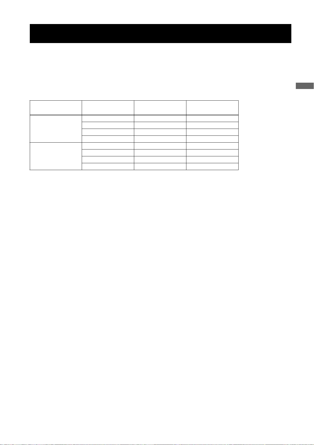
Page 26
Positions of time code-related switches and
information provided
Position of
DISPLAY switch
CTL
TC
UB
1
Position of TCG
switch
SET Time code
F-RUN or R-RUN CTL
F-RUN/SET/
R-RUN
Information Item
Time code
User bits or real-
time, time zone
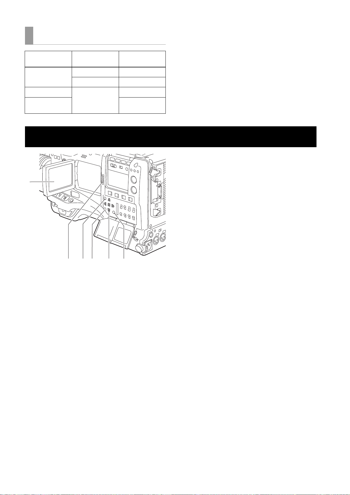
LCD Monitor
5. CURSOR and SET buttons
The four triangular buttons are the CURSOR buttons,
and the center rectangular one is the SET button.
They are used to select a thumbnail and manipulate
the thumbnail menu. For more information, see
[Manipulating Clips with Thumbnails] (page 109).
6. EXIT button
Used to return the display to the previous state when
the thumbnail menu or the property screen is displayed.
23
5
6
4
1. LCD monitor
The LCD monitor displays the video in the viewfinder.
Alternatively, it can show clips on the P2 card in a
thumbnail format.
In thumbnail display mode, clips can be edited or
deleted, or P2 cards can be formatted using the
4.THUMBNAIL MENU button and 5.CURSOR and
SET buttons.
2. OPEN button
Used to open the LCD monitor.
3. THUMBNAIL button
This button switches the content on the 1.LCD monitor
from the video in the viewfinder to clip thumbnails.
Another press switches them back to the video from
the viewfinder.
Note that this switchover is not performed during a
recording or playback.
4. THUMBNAIL MENU button
In thumbnail display mode, this button allows you to
manipulate the thumbnail menu (e.g., to delete clips).
Parts and their Functions:LCD Monitor
26
Page 27
Viewfinder
You can use any of the following viewfinders (extra-cost options) on AJ-HPX2000:
HD Viewfinders: AJ-HVF21G (selectable between 59.94 and 50 Hz)
SD Viewfinders: AJ-VF20WBP (59.94 Hz), AJ-VF15BP (59.94 Hz), AJ-VF20WBE (50 Hz), and AJ-VF15BE (50 Hz)
Use the VF TYPE menu options on the SYSTEM MODE screen on the SYSTEM SETTING page to adjust the appropriate
settings for the viewfinder that will be used. We recommend using a HD viewfinder when the camera-recorder is used in
HD mode or an SD viewfinder when it is used in SD mode. Depending on the mode, some types of video are unavailable
as shown below (
z: the finder shows nothing on a black screen).
Parts and their Functions
Mode
HD
SD
Video seen through
viewfinder
Video from camera
Playback ±±*1*
Return video (HD-Y) ± z
1394/HD-SDI input (HD) ±±*
Video from camera
Playback z ±
Return video (VBS) z ±
1394/HD-SDI input (SD) z ±
HD viewfinder SD viewfinder
±±*
±±
1
2
1
Each viewfinder shows return signals and 1394 and SDI input signals in the recording formats assigned to the camerarecorder.
*1: Down-converted signals
*2
: When the OUTPUT SEL (output signal selection) switch (page 19) of the camera-recorder is set to CAM, a black screen is displayed.
Parts and their Functions:Viewfinder
27
Page 28
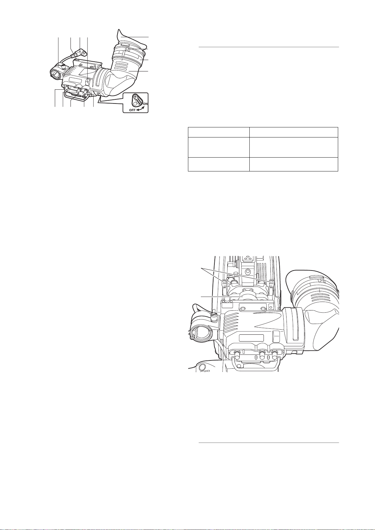
13 14 11 7
9
9. Eyepiece
10
12
1
8
23
45 6
1. Viewfinder (optional accessory)
During recording or playback, the viewfinder displays
the video image in monochrome. It also displays
warnings, messages, zebra patterns, markers (safety
zone and center markers), etc.
2. ZEBRA (zebra pattern) switch
This switch is used to display the zebra pattern in the
viewfinder.
ON: Zebra pattern displayed.
OFF: No zebra pattern displayed.
3. TALLY switch
Used to control the 7.front tally lamp.
Note
Do not leave the eyepiece aimed at the sun. Doing so
may damage the internal components.
10.Diopter adjustment ring
Use this to make adjustments in line with your diopter,
in order to obtain optimum clarity in the viewfinder
image.
The adjustable range of the viewfinder view angle is
shown in the following table.
Product Number Adjustable range
AJ-HVF21G
AJ-VF20WBP
AJ-VF20WBE
AJ-VF15BP
AJ-VF15BE
For an eyepiece for presbyopia, consult the dealer.
–0.9 D to –4.4 D
+1.1 D to –3.4 D
11.Connecting plug
12.Locking ring
13.Microphone holder
HIGH: Front tally lamp brightly illuminated.
OFF: Front tally lamp stays off.
LOW: Front tally lamp dimly illuminated.
4. PEAKING control
Used to adjust the outlines of the video image in the
viewfinder for easier focusing. This does not affect the
signal output from the camera.
5. CONTRAST control
Used to adjust the contrast of the video image in the
viewfinder. This does not affect the signal output from
the camera.
6. BRIGHT control
Used to adjust the brightness of the video image in the
viewfinder. This does not affect the signal output from
the camera.
7. Front tally lamp
This lamp is activated when the 3.TALLY switch is
positioned at [HIGH] or [LOW], and stays on during
recording. It also blinks in synchronisation with the
REC lamp in the viewfinder, and provides alerts.
Use the TALLY switch to change the intensity of the
lamp to ([HIGH] or [LOW]).
14.Viewfinder stopper
Used to attach or remove the viewfinder.
16
15
15.Viewfinder left-right position anchoring ring
Used to adjust the side-to-side position of the
viewfinder.
16.Viewfinder front-back position anchoring
lever
Used to adjust the fore-and-aft position of the
viewfinder.
8. Back tally lamp
This lamp stays illuminated during shooting. It also
blinks in synchronisation with the REC lamp in the
viewfinder, and provides alerts.
When the lever is positioned at [OFF], the back tally
lamp is hidden.
Parts and their Functions:Viewfinder
28
Note
For more information, see the instruction manual for
the viewfinder.
Page 29
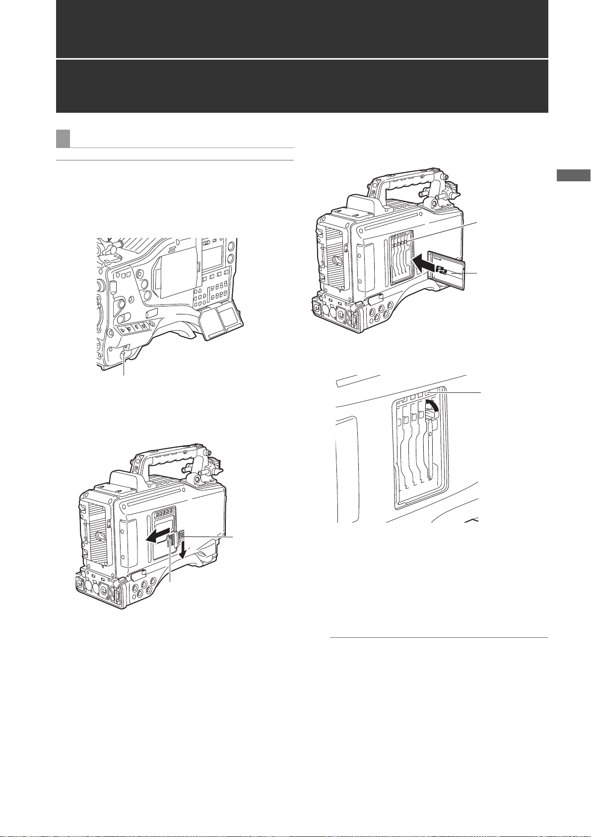
Recording and Playback
P2 Cards
Inserting P2 Cards
Note
When using the camera-recorder for the first time, be sure
to set the time data beforehand. On how the time data is
set, see [
Setting Time Data] (page 55).
1 Turn on the POWER switch.
POWER: ON
2 While pressing down the slide lock button, slide the
slide-out door to the left.
The door opens.
3 Insert a P2 card into the P2 card slot until the EJECT
button pops up.
Recording and Playback
EJECT button
The card must be
inserted with the
logo right way
up.
4 Tilt up the popped-up EJECT button, to lock-in the P2
card.
P2 CARD
ACCESS
LED
Slide-out door
Slide lock
button
5 Insert a P2 card into camera-recorder. The P2 CARD
ACCESS LED for the appropriate slot indicates the
status of the P2 card.
For how the P2 card status is indicated, see [P2
CARD ACCESS LED and status of P2 cards] (page
30).
6 Close the slide-out door.
Note
Do not leave the slide-out door open when moving
camera-recorder.
Recording and Playback:P2 Cards
29
Page 30
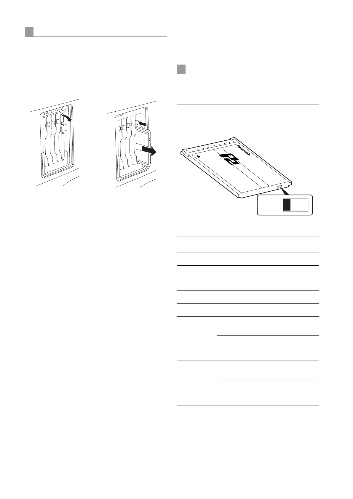
Removing P2 Cards
1 While pressing down the slide lock button, move the
slide-out door to the left.
The door opens.
2 Tilt down the EJECT button.
3 Then, depress the EJECT button to release the P2
card so that you can remove it.
<For Your Information>
The P2 CARD ACCESS LEDs may be set to stay off using
the menu option ACCESS LED. This option can be found
on the <OPTION MODE> screen, which is accessible from
the SYSTEM SETTING page.
To Prevent Accidental Erasure of P2 Card Content
To prevent the content of a P2 card being accidentally
erased, position the write-protect switch on the P2 card at
[Protect].
Note
Write-protect switchover can be performed while the card
is being accessed (during recording or playback), but does
not take effect until access to the card ceases.
Tilt down the EJECT
button.
Depress the tilted-down
EJECT button to release
the P2 card.
Notes
z After insertion, do not remove the P2 card while it is
being accessed or recognized (the P2 card access LED
flashes orange), or the P2 card may fail. If your unit is not
set to turn on the P2 CARD ACCESS LED, before
removing the card ensure that pre-recording and/or
voice memo recording have finished (the P-REC
indication has stopped blinking and the V mark or VOICE
REC indication on the viewfinder screen has turned off)
after stopping recording or playback.
z If a P2 card being accessed is removed, the viewfinder
displays “TURN POWER OFF” and camera-recorder
gives a warning using an alarm and the WARNING LED.
In addition, all P2 CARD ACCESS LEDs blink rapidly in
green. If this is the case, turn the power off. For more
information on warning indications, see [Warning
System] (page 145).
z If a P2 card is removed while being accessed, clips on it
may become irregular. Check the clips and restore them
if required. For more information about how to restore
clips, see [Restoring Clips] (page 117).
z
If a P2 card being formatted is removed, it may be not be
formatted properly. In this case, the viewfinder displays
“TURN POWER OFF”. If this message appears, turn off the
power, then restart camera-recorder to reformat the card.
z If a P2 card is inserted while another P2 card is being
played back, the inserted P2 card is not recognised and
the P2 CARD ACCESS LED for that card does not come
on. Card recognition starts when the playback ends.
z Even if a P2 card is inserted in a vacant slot while
recording, the media may not be recognized during the
following times:
Immediately after pre-recording
Immediately before or after switching from the first
P2 card for recording to the second one, when data
are recorded on multiple cards spanning from one to
the other (hot-swap recording)
Protect
Write-protect switch
P2 CARD ACCESS LED and status of P2 cards
P2 CARD
ACCESS LED
Stays on in
green
Stays on in
orange
Blinks in orange ACCESSING Writing or reading being
Blinks rapidly in
orange
Blinks slowly in
green
Stays off NOT
* The mode check indication is shown in the viewfinder. For more
information, see [Viewfinder Status Indication Layout] (page 70).
The access LED located on the display window blinks
when reading or writing data from or to any of the P2 cards
inserted in Slots 1 - 5 or stays illuminated when any of the
cards are recordable. It stays off when none of the P2
cards are recordable.
MODE CHECK
indication*
ACTIVE Writing and reading
ACTIVE Writing and reading
INFO READING Recognaising the P2 card.
FULL The P2 card has no free
PROTECTED The write-protect switch on
SUPPORTED
FORMAT ERROR The P2 card is not properly
NO CARD No P2 card is inserted.
Status of P2 Card
enabled
enabled. The card is
recordable (loop recording
also enabled).
performed.
space. Only reading is
enabled.
the P2 card is positioned at
[PROTECT]. Only reading
is enabled.
The card is not supported
by your unit. Replace the
card.
formatted. Reformat the
card.
Recording and Playback:P2 Cards
30
Page 31

How to handle data recorded on P2 cards
The P2 card is a semiconductor memory card that is used as the recording medium in the professional video production
and broadcasting devices that make up the DVCPRO P2 Series.
z Since data recorded in the DVCPRO P2 format or AVC-
Intra (option) are in a file format, they have excellent
compatibility with PCs. The file structure is a unique
format, which in addition to video and audio data in MXF
files contains various other important information items.
The folder structure links the data as shown on the right.
Changing or deleting just one information component
could make it impossible to recognize the data as P2
data or use the card in a P2 device
z When transferring data from a P2 card to a PC, or when rewriting data saved on a PC to a P2 card, to prevent data loss
be sure to use the special P2 Viewer software. Download it from the following website.
(Compatible with the Windows Vista, Windows XP and Windows 2000 operating systems.)
https://eww.pavc.panasonic.co.jp/pro-av/
z When using regular IT tools such as Microsoft Windows Explorer or Apple Finder to transfer data to a PC, follow the
instructions below. However, be sure to use the P2 Viewer when returning data to a P2 card.
Transfer the corresponding CONTENTS folder and LASTCLIP.TXT file together as a set.
Do not transfer individual files from the CONTENTS folder.
When copying, copy the LASTCLIP.TXT file at the same time as the CONTENTS folder.
When transferring multiple P2 cards to a PC, create a folder for each P2 card to prevent clips with the same name from
being overwritten.
Do not delete data from the P2 card.
Before using a P2 card, be sure to format it with a P2 device.
Device:\
CONTENTS
AUDIO
CLIP
ICON
PROXY
VIDEO
VOICE
LASTCLIP.TXT*
All these folders are required.
* This is the file in which the
information on the final clip
that was recorded with the P2
device is written.
Recording and Playback
z
Microsoft and Windows are registered trademarks of the Microsoft Corporation in the USA and other countries.
z Apple and Macintosh are registered trademarks of Apple, Inc., in the USA and other countries.
Recording and Playback:How to handle data recorded on P2 cards
31
Page 32

Basic Procedures
2
12345
3
This section describes the basic procedure for shooting
and recording. Before you embark on a shoot, pre-inspect
your system to ensure that it works properly.
* For directions on inspecting your memory card camera-recorder, see
[Inspections Before Shooting] (page 138).
Battery Set-up to P2 card Insertion
1 Insert a charged battery pack.
2 Turn on the POWER switch and ensure that more
than four segments of the battery-remaining amount
indication bar are illuminated.
z If the number of illuminated segments is fewer than
five, first check the battery placement. If placement
is not the problem, replace the battery with a fully
charged one.
3 Insert a P2 card and ensure that the P2 CARD
ACCESS LED stays on in orange or green. Then,
close the slide-out door.
When more than one P2 card slot contains a P2 card,
the card in the slot with the lowest number is used
first. However, regardless of slot number, a P2 card
inserted later will not be accessed until the other
cards have been used.
Example:
If all five slots contain P2 cards, the cards are used in
order of slot numbers 1
the P2 card in Slot 1 is removed and then re-inserted,
the cards will be used in the following order:
>3>4>5>1.
2
>2>3>4>5. However, if
Note that the recording order is retained even if the power
is turned off. When the power is next turned on, the last
card written before powering-down will be the target card.
Note
When “SLOT1” is selected for the menu option P.ON REC
SLOT SEL, recording starts from the P2 card inserted in
the smallest slot number, after the power is turned on.
This option is found in the REC FUNCTION screen on the
SYSTEM SETTING page.
Switch Setting
When a battery and P2 cards are installed, set the
switches as detailed below, before starting to use your unit.
Setting the switches before shooting and recording
Iris: Auto
USER MAIN:
This switch is factory-set to
perform slot selection.
GAIN:
Normally, this should be set to 0 dB.
If conditions are too dark, an
appropriate gain level should be set.
OUTPUT:
CAM/AUTO KNEE ON
AUDIO SE LEC T
CH 1/CH 2:
AUTO
TCG:
F-RUN or
R-RUN
Notes
z The USER MAIN button is factory-set to perform the slot
selection function, which selects the target card from
among several P2 cards.
When a new target P2 card is selected, the appropriate
slot number appears on the P2 card remaining amount
2
1
indicator in the viewfinder.
For more information about the indications in the
viewfinder, see [
(page 70).
z SLOT SEL function is enabled during recording. Until the
P2 card on which images are recorded has been switched
completely, [SLOT SEL] blinks on the viewfinder. If the
[SLOT SEL] operation cannot be executed for any reason,
for instance immediately after starting recording or
switching the P2 card on which images are recorded,
[SLOT SEL INVALID] is displayed.
Viewfinder Status Indication Layout]
Recording and Playback:Basic Procedures
32
Page 33

Shooting
White/Black Balance Adjustment to Recording Completion
For shooting, follow the steps below.
1 Select a filter according to light conditions.
2A When the white balance is saved:
Position the WHITE BAL switch to [A] or [B].
2B
When the white or black balance is not saved and
you have no time to adjust the white balance:
Position the WHITE BAL switch to [PRST].
This adjusts the white balance against the filter
according to the position of the FILTER control.
2C If the white balance is adjusted on the spot:
Position the WHITE BAL switch to [A] or [B] and shoot
a white test subject so that it appears at the center of
the screen. Then, follow the steps below to adjust the
white balance.
1. Press the AUTO W/B BAL switch toward [AWB] to
adjust the white balance.
2. Press the AUTO W/B BAL switch toward [ABB] to
adjust the black balance.
3. Press the AUTO W/B BAL switch toward [AWB] to
adjust the white balance again.
White/Black balance adjustment to recording completion
Recording and Playback
13 2A, B, C2C4 5, 6
For directions on making adjustments, see [
the White Balance] (page 45) and [Adjusting the Black
Balance] (page 48).
Adjusting
3 Point the camera at your subject to adjust the focus,
and zoom.
4 To use the electronic shutter, set the shutter speed
and operation mode.
For more information, see [
Shutter] (page 49).
Setting the Electronic
5 Press either the REC START/STOP button, REC
button on the handle or VTR button at the lens to start
recording.
During recording, the REC lamp in the viewfinder
stays illuminated.
6 To stop recording, press either the REC START/STOP
button, REC button on the handle or VTR button at
the lens.
The REC lamp in the viewfinder goes out.
Operation Buttons
During recording, all operation buttons (REW, FF, PLAY/
PAUSE, STOP) are disabled.
Recording and Playback:Basic Procedures
33
Page 34

Normal Recording
REC START/STOP button, REC button on the handle or VTR button at the lens starts recording of video and sound on the
P2 card. A cluster of data that consists of video and sound generated through a shooting action, together with such added
information as meta data, is called a “clip”.
Normal Recording and Native Recording
In the unit, the camera’s recording method is selectable
between the Native recording method with the frame rate
unchanged and the normal recording method pulling the
frame rate down to 59.94 or 50 frames.
Normal recording (Pull-down recording)
Images at 24P (23.98P: referred to as 24P) are pulled down
in 2:3 mode. Images at 30P (29.97P: referred to as 30P) are
pulled down in 2:2 mode and recorded as 59.94i or 59.94P
(referred to as 60i and 60P). Images at 25P are recorded as
50i or 50P with 2:2 pulled down. 1080i and 480i support
24PA (2:3:3:2 Advanced Pull down) as well.
AVC-Intra (optional) does not support pull-down recording.
Example of 24P Over 60i
Camera
recording
2:3 pull down
= recording
Ao Ae Bo Be Bo Ce Co De Do De
Example of 720P 24P Over 60P
Camera
recording
2:3 pull down
= recording
A
Effective frames
BA C D
BA C D
BB C DD
Native recoding
This recording method extracts and records effective frames
at the frame rates of the AVC-Intra recording (optional) in
1080i, and DVCPRO HD and AVC-Intra recording (optional)
in 720P.
For 720P, it is possible to record images where the length is
2 to 2.5 times longer than the pull-down recording.
Even in Native recording, the rate for outputting camera
images and playback images is 59.54 or 50 frames that are
pulled down.
Example of 1080-24PN (Native)
Camera
recording
2:3 pull down
Recording
Ao Ae Bo Be Bo Ce Co De Do De
Example of 720-24PN (Native)
Camera
recording
2:3 pull down
Effective frame
Recording
A
BA C D
BA
BA C D
BB C DD
BA
C
D
DC
Recording and Playback:Normal Recording
34
Page 35

Notes
z The recording will start from the top frame of a five-frame
cycle for 24P/24PA recording, a four-frame cycle for 24P
native recording or a two-frame cycle for 30P and 25P of
720P, respectively. Therefore, the time code may be
discontinued when recording clips continuously in
different modes during the recording cycle.
z Even if a P2 card has just been inserted, or the power
has been just turned on, you can start recording using
the internal memory of camera-recorder. In this case,
recording cannot be stopped until the P2 card is
recognised. If the inserted card is not recognized as a
recordable P2 card, the record in internal memory is
instantly discarded, and the message “CANNOT REC”
message is displayed on the viewfinder. Press the
MODE CHECK button to check P2 card status
(displayed in viewfinder).
PRE-RECORDING function
REC START/STOP button
Mode check button
Recording and Playback
The internal memory of your unit is capable of storing
several seconds of video and sound data coming from the
camera. This capability can be used to record video and
sound several seconds before either the REC START/
STOP button, REC button on the handle or VTR button at
the lens is pressed to start recording. To use this function,
the menu option PRE REC MODE must be set to “ON”.
The storage duration of the internal memory can be set
from the menu option PRE REC TIME. PRE REC MODE
and PRE REC TIME menu options can be found in the
REC FUNCTION screen on the SYSTEM SETTING page.
The function of the menu option PRE REC MODE may be
assigned to a desired user button by using any one of the
menu options USER MAIN SW, USER1 SW, or USER2 SW.
These options can be found in the USER SW screen,
which is accessible from the CAM OPERATION page.
These are the options for PRE REC TIME.
1-15 SEC (for DVCPRO 25M or DV)
1-8 SEC (for DVCPRO HD or 50M):
Specify the duration for which data may be recorded
before either the REC START/STOP button, REC button
on the handle or VTR button at the lens is pressed.
REC/PAUSE
(Recording pauses)
B
B
New clip
C
Real-time video
Real-time sound
Specified PREREC duration
Content on P2 card
REC start
(Recording starts)
A
Previous clip
A
Notes
z “P-REC” indication when the “PRE REC MODE”
menu option is set to OFF
After recording is stopped, the “P-REC” indication
remains displayed until all video and sound are recorded
on the P2 card, even if the PRE REC MODE menu
option is set to OFF. For details of the [P-REC] display,
refer to [30.INTERVAL REC/PRE RECORDING
indication/ SD memory card remaining free space (page
75)] in [Viewfinder Status Indication Layout].
z Immediately after the power is turned on, the menu
option PRE REC TIME is selected and/or the storage
duration is changed, the content in internal memory will
be undefined. In these situations, the video or sound will
not be recorded for the duration specified, even if either
the REC START/STOP button, REC button on the
handle or VTR button at the lens is pressed to start
recording.
z A P2 card that has been just inserted takes some time to
recognise. In this situation, video or sound may not be
recorded for the duration specified, even if either the
REC START/STOP button, REC button on the handle, or
VTR button at the lens is pressed to start a recording.
z The internal memory does not store video or sound
when a playback or recording review is being performed.
For this reason, no video or sound can be recorded
during such operation.
z When recording starts, the time code indication (TCG)
may be shown as “HOLD” until the P2 card has been
recognised.
z During recording of IEEE1394 input or INTERVAL REC
operation, PRE RECORDING is not available.
Recording and Playback:PRE-RECORDING function
35
Page 36

Loop Recording
When two or more P2 card slots contain cards, this
function allows the target P2 card to be switched in order.
Even when the free space of a P2 card is used up, this
function continues recording while erasing existing data.
To use this function, the menu option LOOP REC MODE
must be set to “ON” The option LOOP REC MODE can be
found in the <REC FUNCTION> screen on the SYSTEM
SETTING page.
Before loop
recording starts
Recording starts
Recording
Cycle 1
Recording
Cycle 2
Data are recorded by connecting the unrecorded sections on
the P2 card (in the sequence of A to B to C). When the
remaining recording capacity is less than 30 seconds, A is
deleted, and data are record on C up to FULL (remaining
memory capacity is 0), and then new data are recorded (D).
Card1 Card2 Card3
No content
A
D
Content
recorded
B
B
C
C
Notes
z When the loop recording capability is used, each P2
card must have at least one minute of free space.
z During loop recording, the P2 CARD ACCESS LEDs for
all target P2 cards illuminate in orange. Note that if any
of the target P2 card is removed, loop recording stops.
z When the menu option LOOP REC MODE is set to ON,
the viewfinder and display window both show “LOOP”.
However, when only one card is inserted, or when each
card has less than one minute of free space, the loop
recording capability does not work, even if the option
LOOP REC MODE is set to ON. If this is the case, the
indication “LOOP” flashes in the viewfinder and on the
display window.
z When the menu option LOOP REC MODE is set to ON,
the P2 card remaining free space indicates the minimum
guaranteed recording time.
recording time means the guaranteed time or length of
recorded data when LOOP REC stops immediately after
deleting old data.
z During recording of IEEE1394 input or INTERVAL REC
operation, LOOP REC is not available.
The minimum guaranteed
Terminating the Loop Recording Mode
Interval Recording
It is possible to record in intervals of one frame as the
shortest length by using the internal memory of the unit.
To use this option, open the REC FUNCTION screen from
the SYSTEM SETTING page, and set the interval recording
mode, REC TIME, PAUSE TIME and TAKE TOTAL TIME for
the menu option INTERVAL REC MODE. When the settings
are finalized, TOTAL REC TIME needed on the P2 card is
automatically calculated and displayed.
The following are the options for INTERVAL REC MODE:
OFF:
No interval recording performed.
ON:
Interval recording performed.
ONE SHOT:
Performs “one-shot” recording for the duration
specified under the REC TIME option by pressing
either the REC START/STOP button, REC button on
the handle, or VTR button at the lens.
You can terminate the loop recording mode by either:
z Turning off the POWER switch of camera-recorder; or
z Setting the menu option LOOP REC MODE to “OFF”.
Notes
z When executing interval recording, data cannot be output
with IEEE1394. When the 1394 CONTROL is set to
[BOTH], it is also impossible to control external devices.
z
The shortest recording time, stand-by time, and the set
value of the cut-off unit frame number*
the recording method as follows.
Recording method
1080i
720P
SD MODE
*1 For instance, interval recording is at every 24 frames
since frames are cut off every two frames even if the
REC TIME is set to 1 second (= 25 frames) in the 25PN
mode of 720P.
60i, 50i
30P, 25P (Pull down)
30PN, 25PN (Native)
24P, 24PA (Pull down) 5 frames
24PN (Native) 4 frames
60P, 50P
30P, 25P (Pull down)
30PN, 25PN (Native) 2 frames
24P (Pull down) 5 frames
24PN (Native) 4 frames
60i, 50i
30P, 25P (Pull down)
24P, 24PA (Pull down) 5 frames
1
may vary with
Unit frame
number
1 frame
1 frame
1 frame
Recording and Playback:Loop Recording
36
Page 37

Shooting procedures when INTERVAL REC is ON
Shooting procedures for the ONE SHOT mode of
INTERVAL REC
1 Following basic operations of shooting and recording
according to “
securely.
Basic Procedures”, lock the camera
2 Check that “i” is blinking in the display, and that the
interval recording mode is selected.
3 Press either REC START/STOP button, REC button on
the handle, or VTR button at the lens.
Interval recording starts. Recording automatically stops
after the specified TAKE TOTAL TIME, and the entire
recording is generated as one clip.
“i” starts blinking in the display when the internal
recording mode is selected. “iREC” illuminates after
recording starts. “iREC” blinks during a pause.
The display in the viewfinder is the same as that in the
display window.
The tally lamp illuminates during recording. If PAUSE
TIME is set at 2 minutes or longer, the tally lamp
illuminates at 5-second intervals to indicate that it is
paused. The tally lamp also blinks 3 seconds before
recording starts.
iREC start
Real-time video
Sound
Content on P2 card
Time Axis
t1
1
t1
t2 t2
TAK E TOTAL T I M E
(Time necessary for shooting)
12233
(Recording time on P2 card)
t1
N-1
TOTAL REC TIME
t1
N-1
t2
N
t1
N
One clip
REC TIME
(Recording
time=t1)
PAU S E T I M E
(Recording
time=t2)
After setting the INTERVAL REC mode, follow these steps:
1 Following basic operations of shooting and recording
according to “
securely.
Basic Procedures”, lock the camera
2 Press either the REC START/STOP button, REC
button on the handle, or VTR button at the lens.
The AJ-HPX2000 automatically goes into ONE SHOT
pause mode after the specified REC TIME.
3 Performs recording for the duration specified under
the REC TIME option by pressing either the REC
START/STOP button, REC button on the handle, or
VTR button at the lens, and returns to ONE SHOT
pause mode.
4 Press the STOP button.
The video and sound stored in memory are generated
as one clip.
Real-time video
Sound
Content on P2 card
iREC
Previous clip
start
Time
Axis
A
t
To check the previous recording during a pause
A
B
One clip
iREC
start
B
STOP
button
t
REC TIME
(Recording
time=t)
Recording and Playback
For continuous recording
Press either the REC START/STOP button, REC button on
the handle, or VTR button at the lens, again. Interval
recording resumes.
To stop recording
Press the STOP button. Recording stops. Then, the camera
accesses the P2 card to record the video stored in memory
before recording stops. The record from the beginning of the
interval recording to the moment of pressing the STOP
button is generated as one clip.
To stop the Interval recording mode
z Setting the menu option INTERVAL REC MODE to “OFF”.
When INTERVAL REC HOLD is set to [OFF], the mode
returns to ordinary recording mode if the POWER switch of
the unit is turned OFF.
If INTERVAL REC HOLD is set to [ON], the interval recording mode will not change even if the POWER switch is
turned OFF.
Press the RET button at the lens to put the AJ-HPX2000 into
REC REVIEW mode. ONE SHOT operation continues after
the REC REVIEW.
To divide clips or to change the P2 card used for
recording
Even during ONE SHOT mode, clips will not be generated
on the P2 card until the STOP button is pressed. Press the
STOP button, and stop ONE SHOT mode operation.
To stop the ONE SHOT mode of INTERVAL REC
z Set the menu option INTERVAL REC MODE to “OFF”.
When INTERVAL REC HOLD is set to [OFF], the mode
returns to ordinary recording mode if the POWER switch of
the unit is turned OFF.
If INTERVAL REC HOLD is set to [ON], the interval recording mode will not change even if the POWER switch is
turned OFF.
Recording and Playback:Interval Recording
37
Page 38

During INTERVAL REC mode general notes
z
Sound
By selecting ON/OFF for the menu option AUDIO REC in
the REC FUNCTION screen, it is possible to specify
whether or not sound will be recorded during interval
recording.
z Record/Playback Buttons
During interval recording, all operation buttons other than
STOP (REW, FF, PLAY/PAUSE) are disabled. However,
during a pause in ONE SHOT mode, REC REVIEW can
be executed with the RET button on the lens.
z
If the power is turned off during recording
If the AJ-HPX2000 is turned off during interval recording,
the video stored in memory is recorded onto the P2 card,
and then the camera automatically turns off.
z To start emergency recording during a pause
By setting the REC button to USER MAIN or USER1/
USER2, emergency recording can be performed during
a pause by pressing the button. Pause time
measurement continues after such emergency
recording.
◆Note
However, this function does not work when the recording
signals are in 24P, 24PA or 24PN (Native) mode.
z
Time code indication
When recording starts, the time code (TCG) display may
not update until the unit recognizes the P2 card.
z Thumbnail operation and menu operation
Thumbnail operation does not work during the
INTERVAL REC mode operation. Press the STOP
button before operating thumbnails.
When standby time is set to 1 minute or more or when in
ONE SHOT mode, the following restrictions apply even
though the menu can be operated during stand-by
mode.
The respective settings or SYSTEM MODE, REC
SIGNAL, CAMERA MODE, REC MODE, 25M REC
CH SEL, and PC MODE cannot be changed.
The respective settings for SD CARD READ/WRITE,
LENS FILE CARD R/W, READ USER DATA, and
READ FACTORY DATA cannot be executed.
z Removing cards
During INTERVAL REC mode operation, the P2 card
access LED for the inserted P2 card blinks in orange. Do
not remove the P2 card during this status. If you should
remove the card accidentally, restore clips. However, even
if the clips are restored, the last 3 to 4 seconds up to a
maximum of about 10 seconds of the recording may be
lost if the P2 card is removed while recording onto multiple
P2 cards. For more information on how to fix clips, see
[Restoring Clips] (page 117).
z Operation mode
INTERVAL REC does not work when “1394” is selected for
the menu option REC SIGNAL. The menu option REC
SIGNAL is found in the SYSTEM MODE screen on the
SYSTEM SETTING page. For more information, see
[Recording Setting and Operation Mode] (page 41).
Recording and Playback:Interval Recording
38
Page 39

Recording Review Function
When recording is paused, pressing the RET button
automatically locates the last two seconds of video just
recorded, and the viewfinder provides video playback.
After playback, the camera-recorder is again ready to start
recording.
The picture location/playback duration can be increased to
up to 10 seconds by continuously pressing the RET button.
For short clips, however, when the start of a clip is located,
continuously pressing the RET button does not play back
any clips before that clip.
The function of the RET button may be assigned to a
desired user button by using one of the menu options
USER MAIN SW, USER1 SW or USER2 SW. These
options can be found in the <USER SW> screen on the
CAM OPERATION page.
When recording is paused, pressing the PLAY/PAUSE
button plays back the last recorded clip, from the
beginning. After completion of playback, the camerarecorder enters the stopped state.
Recording and Playback
Recording starts
Recorded clip
The PLAY button plays back
the clip from the beginning.
Recording pauses
2-10 Seconds
The RET button
puts the camerarecorder into REC
REVIEW mode.
Notes
z Set the menu option RET SW (found on the SW MODE
page for CAM OPERATION) to R. REVIEW.
z When the OUTPUT SEL switch on the side panel is
positioned at [MEM], the video for REC REVIEW is
output from the video output connectors (VIDEO OUT
and MON OUT connectors), and also to the viewfinder.
Note that when a backup device is connected to back up
the video the pictures for REC REVIEW are backed up.
Recording and Playback:Recording Review Function
39
Page 40

Normal and Variable Speed Playback
The PLAY/PAUSE button provides monochrome playback
through the viewfinder and color playback on the LCD
monitor. A color video monitor connected to the VIDEO
OUT or MON OUT connector of camera-recorder also
provides color playback.
The VIDEO OUT connector outputs an SDI playback (to
view the playback, the OUTPUT SEL switch on the side
panel must be positioned to [MEM]).
Variable speed playback
The FF and REW buttons provide 32
playbacks and fast reverse playbacks.
When playback is paused, the FF button locates the
beginning of the next clip while maintaining the pause
mode.
When playback is paused, the REW button locates the
beginning of the current clip while maintaining the pause
mode.
a and 4a fast
Text Memo Function
Notes
z The camera-recorder cannot play back clips where the
system mode differs. If this is the case, set the system
mode of camera-recorder to the format of the desired
clip before playing it back.
z When a P2 card has been just removed or inserted, or
when the power has been just turned on for playback, it
may take some time for camera-recorder to read clip
information. If this is the case, the viewfinder displays
“UPDATING”. If data is played back when the P2 card is
being recognized, the message “CANNOT PLAY” will be
displayed.
z If a P2 card is inserted while another P2 card is being
played back, the clips on the inserted P2 card will not be
played back. A P2 card inserted during playback will be
recognised after playback ends.
z If you perform variable speed playback on a clip split
across more than one P2 card, sound may disappear for
a moment. This is not a fault.
Text memos are time-coded thumbnails added to any
video point when a clip is being recorded or played back.
The Text Memo button adds text memo information at the
appropriate point. You can edit added text memos using
the P2 viewer.
Through a thumbnail display, you can choose and play
back the text memo point or copy any portion. For more
information, see [Text Memo] (page 115).
Text MEMO button
Notes
z One clip can have up to 100 text memos.
z Text memos can also be recorded when the LCD monitor
is in thumbnail mode.
to the position on the clip where the cursor is set (normally
at the beginning) only.
z Text memos cannot be recorded when the color bar is
output or the unit is in LOOP REC mode and INTERVAL
REC mode.
z For a clip with voice memos added through the AJ-
SPX800 or any other camera-recorder, you can record
up to 100 text and voice memos in combination. For
information about voice memos, see the instruction
manual for the AJ-SPX800.
In this case, the text memo is added
Recording and Playback:Normal and Variable Speed Playback
40
Page 41

Shot Mark Function
A shot mark is added to the thumbnail of a clip to
distinguish that clip from others. With the LCD monitor,
only clips that have shot marks can be viewed and/or
played back.
Adding Shot Marks
To add a shot mark during recording, press the SHOT
MARK button. The viewfinder displays “MARK ON” and
adds a shot mark to the thumbnail of the appropriate clip.
Another press of the button erases the shot mark.
SHOT MARK
button
Shot marks may also be added or erased using clip
thumbnails. For more information, see [Shot Mark] (page
115).
Notes
z When the color bar is output or the unit is in LOOP REC
mode and INTERVAL REC mode, it is impossible to add/
delete shot marks.
z It is impossible to add shot marks to incomplete clips
(refer page 111).
z For clips recorded on plural P2 cards or clips split on a
P2 card (refer to
to the top clip only.
Notes on page 10), a shot mark is added
Recording and Playback
Recording Setting and Operation Mode
AJ-HPX2000 recording mode works according to the priorities outlined in the following table, relative to the setting of the
menus and switches.
Functional
operation mode
USB device
USB host USB HOST Disabled Disabled Disabled Disabled Enabled Enabled Disabled
1394 Input record
INTERVAL REC
LOOP REC
Normal Recording OFF
* Disabled for color bars
PC MODE
USB
DEVICE
OFF
Menu switches related to system/recording Buttons
REC
SIGNAL
Disabled Disabled Disabled Disabled Disabled Disabled Disabled
1394 Disabled Disabled Disabled Enabled Enabled Disabled
CAMERA
VIDEO
SDI (optional)
INTERVAL
REC MODE
ON or
ONE SHOT
OFF
LOOP REC
MODE
Disabled Disabled Disabled Disabled Disabled
ON
PRE REC
MODE
Enabled
1s - 8s/15s
Enabled
1s - 8s/15s
Recording a
Text M emo
Disabled Disabled Disabled
Enabled* Enabled* Enabled
Shot Mark
Proxy
recording
(optional)
Recording and Playback:Shot Mark Function
41
Page 42

Adjustments and Settings for Recording
Multi Format
Video system and Recording format
The unit employs a progressive scan (full pixel reading) CCD system.
With combinations of the SYSTEM MODE and CAMERA MODE menu options on the SYSTEM MODE screen o
SYSTEM SETTING menu, you can select an image system from among 23 types*
formats.
In any image system, the CCD operates in progressive (non-interlace) scan mode.
menu option, you can record external input signals such as 1394 and SDI (optional).
When the AVC-Intra codec board (AJ-YBX200G, optional) is installed
*1
1
including HD (1080i, 720P) and SD
In addition, through the REC SIGNAL
Selecting a recording signal and method
n the
SYSTEM MODE menu option
Allows you to select a combination of system
frequency (59.94 Hz or 50 Hz) and signaling system
(1080i, 720P, 480i, or 576i). When a change has been
made to the SYSTEM MODE option, the viewfinder
indicates “TURN POWER OFF.” Then, turn the
POWER switch of the camera-recorder off and wait
five seconds or longer before turning the camerarecorder on again.
REC SIGNAL menu option
CAM Signals from the camera are recorded. The
CAMERA MODE option allows you to select
a camera operation mode (frame mode).
1394 Signals from the DVCPRO/DV connector are
recorded. For information about the 1394
connection, see [Connection through the
DVCPRO/DV connector] (page 129).
VIDEO Signals from the GENLOCK IN connector
are recorded when the camera-recorder is in
SD mode (480-59.94i or 576-50i).
SDI Signals from the SDI IN connector are
recorded (when the AJ-YA350AG, an SDI IN
option, is installed).
REC MODE menu option
Used to select the recording mode
For HD mode (1080i, 720P)
DVCPRO HD
The DVCPRO HD format is used to record
video. The pull-down recording is for the 30P,
24P, 24PA and 25P modes.
DVC HD (N)
The native mode used to record video in
DVCPRO HD format. (Only for 720P)
AVC-I 5 0 (when the AVC-Intra codec board is
installed)
The AVC-Intra50 format is used to record
video. The native recording is applied to the
30P, 24P and 25P modes.
AVC-I 100(when AVC-Intra codec board is installed))
The AVC-Intra100 format is used to record
video. The native recording format applies to
the 30P, 24P and 25P modes.
Note
When AVC-Intra 50 or AVC-Intra 100 is selected, the
24PA mode cannot be selected.
Notes
z When VIDEO is selected, video may produce noise
if the signals from GENLOCK IN are non-standard
signals.
z When SDI is selected, the time code or UMID
superimposed on SDI input signals are not
recorded.
CAMERA MODE menu option
Used to select a camera operation mode when the
option REC SIGNAL is set to CAM. For information
about the behavior for each setting, see [
formats and output connector signal formats
Note
When the camera has been switched from 60i, 60P, or
30P to 24P or 24PA, video may produce noise for a
moment because the pull-down five-frame cycle is
adjusted. This is not an abnormal condition.
Adjustments and Settings for Recording : Multi Format
42
Recording
] (page 43).
For SD mode (480i, 576i)
DVCPRO50
The DVCPRO50 format (50 Mbps) is used to
record video.
DVCPRO
The DVCPRO format (25 Mbps) is used to
record video.
DV The DV format is used to record video.
ASPECT menu option
Used to select the aspect ratio for the SD mode (480i
or 576i)
:9 The 16:9 aspect ratio is used to record video.
16
:3 The 4:3 aspect ratio is used to record video.
4
Page 43

Recording formats and output connector signal formats
The table below shows the formats used to record signals from the CCD and externally input signals along with the
formats for signals output from the output connectors.
For 59.94 Hz
SYSTEM
MODE
item
1080-
59.94i
720-
59.94P
480-
59.94i
Menu setting
REC
MODE
item
DVC PRO HD
AVC-I 100
AVC - I 5 0
(optional)
DVC PRO HD
DVC H D (N)
AVC-I 100
AVC - I 5 0
(optional)
DVCPRO50
DVC PRO
DV
REC
SIGNAL
item
CAM
1394
SDI
(optional)
CAM
SDI
(optional)
CAM
1394
SDI
(optional)
CAM
SDI
(optional)
CAM
SDI
(optional)
CAM
1394
VIDEO
SDI
(optional)
Recording Output
CAMERA
MODE
item
Recording
frame
mode
P2 card
recording*
Output
1
frame
mode
Video Sound Video
60i 60i
30P
24P
24PA
60i 60i 60i
30P
24P
60P 60P
30P
24P
60P 60P 60P
30P
24P
60P 60P 60P
30P
24P
60i 60i
30P
24P
24PA
30P Over 60i 30P Over 60i
24P Over 60i
24PA Over 60i
60i 60i
j
60i 60i
j
30PN(Native
24PN(Native
60i 1080i 60i
j
30P Over 60P 30P Over 60P
24P Over 60P 24P Over 60P
60P 60P
j
60P 60P
j
30PN(Native
24PN(Native
60P 60P
j
30PN(Native
24PN(Native
60P 60P
j
30P Over 60i 30P Over 60i
24P Over 60i
24PA Over 60i
60i 60i
j
1080i
)
1080P
)
)
720P 4ch
)
)
)
480i
4ch
4ch or
2ch
*
60i
24P Over 60i
24PA Over 60i
30P Over 60i
24P Over 60i
60P
30P Over 60P
24P Over 60P
30P Over 60P
24P Over 60P
60i
24P Over 60i
24PA Over 60i
5
VIDEO
OUT
connector
(HD SDI)*
Sound
1080i
4ch
720P 4ch
j
j
4
*
*4*
VIDEO
connector
2
(SD SDI)*
Video
525i
525i
525i
5
OUT
Sound
4ch 525i
4ch 525i
4ch or
2ch
3
5
*
VIDEO OUT
(VBS),
MON OUT,
and
REMOTE
connectors
Video
525i
When VF
When VF
connector
connector
is set to
is set to
HD VF
SD VF
1080i 525i
1080i 525i
1080i
(Playback
not
output)
(Playback
not
output)
525i
Adjustments and Settings for Recording
*1 The time code, user bits, and UMID are recorded.
*2 The time code, user bits, and UMID (selectable between ON and OFF) are output.
*3 The EDH (selectable between ON and OFF) and UMID (selectable between ON and OFF) are output. The time code
or user bits are not output.
*4 The SD SDI output is maintained.
4ch for DVCPRO50, 4ch/2ch selectable for DVCPRO and DV
*5
Note
z UMID is not output for recording or playing back in DV format or for playing back DVCPRO HD Native recording clips.
z During playback, the formats for clips in the same system mode are switched automatically and played back.
Adjustments and Settings for Recording : Multi Format
43
Page 44

For 50 Hz
SYSTEM
MODE
item
1080-50i
720-50P
576-50i
Menu setting
REC
MODE
item
DVCPROHD
AVC-I 100
AVC - I 5 0
(optional)
DVCPROHD
DVC HD (N)
AVC-I 100
AVC - I 5 0
(optional)
DVCPRO50
DVCPRO
DV
REC
SIGNAL
item
CAM
1394
SDI
(optional)
CAM
SDI
(optional)
CAM
1394
SDI
(optional)
CAM
SDI
(optional)
CAM
SDI
(optional)
CAM
1394
VIDEO
SDI
(optional)
Recording Output
CAMERA
MODE
item
Recording
frame
mode
P2 card
recording*
Output
1
frame
mode
Video Sound Video
50i 50i
25P
50i
25P
50i 50P
25P
50P 50P 50P
25P
50P 50P 50P
25P
50i 50i
25P
25P Over 50i 25P Over 50i
50i 50i
j
50i 50i
j
50i
25PN(Native
50i 1080i 50i
j
25P Over 50P 25P Over 50P
50P 50P
j
50P 50P
j
25PN(Native
50P 50P
j
25PN(Native
50P 50P
j
25P Over 50i 25P Over 50i
50i 50i
j
1080i
1080P
)
720P 4ch
)
)
576i
4ch
4ch or
2ch
*
50i
50i
25P Over 50i
50P
25P Over 50P
25P Over 50P
50i
5
VIDEO
OUT
connector
(HD SDI)*
Sound
1080i
4ch
720P 4ch
j
j
4
*
*4*
connector
2
(SD SDI)*
Video
625i
625i
625i
5
VIDEO
OUT
Sound
4ch 625i
4ch 625i
4ch or
2ch
3
5
*
VIDEO OUT
(VBS),
MON OUT,
and
REMOTE
connectors
Video
625i
When VF
connector
1080i 625i
1080i 625i
1080i
(Playback
not
output)
(Playback
not
output)
is set to
HD VF
When VF
connector
is set to
SD VF
625i
*1 The time code, user bits, and UMID are recorded.
*2 The time code, user bits, and UMID (selectable between ON and OFF) are output.
*3 The EDH (selectable between ON and OFF) and UMID (selectable between ON and OFF) are output. The time code
or user bits are not output.
*4 The SD SDI output is maintained.
4ch for DVCPRO50, 4ch/2ch selectable for DVCPRO and DV
*5
Note
z UMID is not output for recording or playing back in DV format or for playing back DVCPRO HD Native recording clips.
z During playback, the formats for clips in the same system mode are switched automatically and played back.
Adjustments and Settings for Recording : Multi Format
44
Page 45

Adjusting the White balance and Black Balance
To record high-quality video with the unit, the black and white balances must be adjusted according to conditions.
For higher quality, it is recommended that the adjustments should be made in this order AWB (white balance adjustment)
> ABB (black balance adjustment) > AWB (white balance adjustment).
Adjusting the White Balance
Whenever light conditions change, the white balance must
be re-adjusted.
To adjust the white balance, follow the steps below.
1 Set the switches as illustrated below.
CC/ND FILTER control
4 Adjust the lens iris.
5 Flip up the AUTO W/B BAL switch so that it is
positioned at [AWB], then release it.
The switch returns to the central position with the
white balance automatically adjusted.
Note
To cancel automatic white balance adjustment in
process (the viewfinder displays “AWB ACTIVE”), reposition the AUTO W/B BAL switch at [AWB].
If automatic adjustment is cancelled, the value in
effect before automatic adjustment will be used.
6 During an adjustment, the viewfinder displays the
following message:
Adjustments and Settings for Recording
WHITE BAL: A or B
OUTPUT: CAM
AUTO W/B BAL switch:
Used to perform
AWB.
GAIN:Under normal conditions, set to 0 dB
If it is too dark, an appropriate gain
should be set.
2 Adjust the CC/ND FILTER control according to the
light conditions.
Note
For examples of CC/ND FILTER adjustments, see
[Shooting and Recording/Playback Functions Section]
(page 17).
3 Place a white pattern at a point where the light
conditions match those for the light source of the
subject. Then zoom-in on the white pattern so that
white color appears in the screen. A white object
(cloth or wall) may be used instead of a white pattern.
The illustration below shows the required size for the
white space.
Notes
z Do not include a high-intensity spot in the screen.
z The white object must appear at the center of the
screen.
AWB ACTIVE
7 The adjustment will take effect in a few seconds, and
the following message will appear:
The adjusted value is automatically stored in the
memory specified in Step 1 ([A] or [B]).
AWB A OK 3.2K
8 For the 3200K CC/ND filter, if the subject’s color
temperature is lower than 2300K or higher than
9900K the following message appears:
If the arrow points down (
temperature is lower than the temperature indicated.
If the arrow points up (
higher than the temperature indicated.
;) the actual color
:) the actual temperature is
AWB A OK 2.3K
;
1/4 or more of the screen in width
1/4 or more of the
screen in height
Adjustments and Settings for Recording : Adjusting the White balance and Black Balance
45
Page 46

Detection area for the white balance
Retaining white balances
The detection area for the white balance is selectable
between 90%, 50% and 25%, using the menu option AWB
AREA.
This option can be found in the <WHITE BALANCE
MODE> screen, which is accessible from the CAM
OPERATION page.
The detection area is factory-set to 25%.
90%
50%
25%
When you have no time to adjust the white
balance
Position the WHITE BAL switch at [PRST].
This adjusts the white balance for the filter according to the
position of the CC/ND FILTER control.
When the white balance has not been
automatically adjusted
When the white balance has not been successfully
adjusted, the viewfinder displays an error message.
If one of the error messages listed below appears, take the
appropriate steps, then adjust the white balance again.
If the error message appears after repeated
readjustments, the interior of the unit must be inspected.
For more information, contact your distributor.
Each value in memory is retained even if the camerarecorder is turned off; it will not be lost until the white
balance is re-adjusted. White balances are stored in either
of two systems: A or B.
When the menu option FILTER INH is set to “ON” (default),
each system stores only one value. If this is the case, the
values are not synchronised with the filters.
This option can be found in the <WHITE BALANCE
MODE> screen, which is accessible from the CAM
OPERATION page.
When the menu option FILTER INH is set to “OFF”, the
adjusted value for each filter can be automatically stored in
the memory that corresponds to the position of the WHITE
BAL switch (A or B). Your unit has four built-in filters; it
stores eight (4
a 2) adjusted values.
When the S. GAIN (super gain) function is activated, the
AWB switch does not function and the value set for PRST
is used.
Setting the auto-tracking white balance (ATW)
The unit has an auto-tracking white balance (ATW) feature
that automatically tracks the white balance for pictures
according to lighting conditions.
The ATW feature can be assigned to Position [B] of the
WHITE BAL switch. To do so, the menu option AWB B
must be set to “ATW”. This option can be found in the
<WHITE BALANCE MODE> screen, which is accessible
from the CAM OPERATION page.
The ATW feature may be assigned to the USER MAIN,
USER1, or USER2 button. For more information, see
Assigning Functions to USER MAIN, USER1 and USER2
[
Buttons] (page 51).
Error message Description Remedies
COLOR TEMP.
HIGH
COLOR TEMP.
LOW
LOW LIGHT There is insufficient
LEVEL OVER There is too much
CHECK FILTER The FILTER control
TIME OVER AWB was not
The color
temperature is too
high.
The color
temperature is too
low.
light.
light.
is displaced.
completed within
the time allowed.
Select an appropriate
filter.
Select an appropriate
filter.
Increase the light level
or gain.
Decrease the light level
or gain.
Check the FILTER
control.
Shooting conditions may
be unstable. If flicker
occurs, press the
shutter and readjust the
AWB under stable
conditions.
To cancel the auto-tracking white balance
Press the user button that has the ATW feature assigned,
or change the position of the WHITE BAL switch. Note
that, when the ATW feature is assigned to [B] of the
WHITE BAL switch, the auto-tracking white balance
cannot be cancelled with a user button.
#
< WHITE BALA NCE MODE >
FILTER INH :ON
SHOCKLESS A WB :NORMAL
AWB AREA :25%
AWB B :MEM
ATW SPEED :NORMAL
COLOR TEMP PRE :3200K
AWB A TEMP :3200K
AWB B TEMP :3200K
Note
This function does not guarantee 100% accuracy of the
white balance.
When using the unit, remember that there will be some
allowance in the trackability of changes in lighting
conditions and pull-in accuracy of white balances.
Adjustments and Settings for Recording : Adjusting the White balance and Black Balance
46
Page 47

Setting Color Temperature Manually
The white balance can be manually adjusted by setting the
color temperature. Manual color temperature settings can
be performed for each of the WHITE BAL switch positions:
PRST, A and B.
The color temperature is set using the menu options
COLOR TEMP PRE, COLOR TEMP A, and COLOR
TEMP B.
These options can be found in the <WHITE BALANCE
MODE> screen, which is accessible from the CAM
OPERATION page.
Note
Even if the color temperature has been manually set,
automatic adjustment of the white balance (AWB) records
the color temperature at the time of AWB at the position
where the WHITE BAL switch was located. When the CC
filter position is switched, the value for the color
temperature changes.
#
< WHITE BALA NCE MODE >
FILTER INH :ON
SHOCKLESS A WB :NORMAL
AWB AREA :25%
AWB B :MEM
ATW SPEED :NORMAL
COLOR TEMP PRE :3200K
AWB A TEMP :3200K
AWB B TEMP :3200K
Adjustments and Settings for Recording
Viewfinder displays related to white balance
Viewfinder Screen Status Displays] (page 69).
See [
Adjustments and Settings for Recording : Adjusting the White balance and Black Balance
47
Page 48

Adjusting the Black Balance
The black balance must be adjusted when:
z You use your unit the first time;
z Your unit has not been used for some time;
z The ambient temperature has changed substantially;
z The gain switchover value has been changed; or
z S.GAIN (super gain) has been set with the USER MAIN/
USER1/USER2 button.
1 Set the switches as illustrated below.
AUTO W/B BAL switch:
Used to perform ABB.
OUTPUT: CAM
2 Tilt the AUTO W/B BAL switch so that it is positioned
at [ABB], then release it.
The switch returns to the central position with the
black balance automatically adjusted.
3 During adjustment, the viewfinder displays the
following message:
Notes
z Ensure that the lens connector is connected and
the lens iris is CLOSE.
z During a black balance adjustment, light is
automatically cut off.
z During a black balance adjustment, the gain
switchover circuit is automatically switched.
The viewfinder screen may flicker and/or display
noise; this is not a failure.
If you find the black shading annoying after
z
performing an auto black balance adjustment,
adjust the black shading. To do so, go to the menu
option DETECTION (DIG), move the cursor (
then press the JOG dial button. The menu option
DETECTION (DIG) can be found in the <BLACK
SHADING> screen, which is accessible from the
MAINTENANCE page.
Note that pressing the ABB switch for longer than five
seconds automatically performs an auto black
balance adjustment, followed by an automatic black
shading adjustment. (For more information, see the
menu option SHD. ABB SW CTL in [SW MODE]
(page 175).)
However, when the remote control unit (AJ-RC10G:
optional accessory) is connected, automatic black
shading cannot be executed even if the ABB switch is
held down.
To cancel the automatic black balance adjustment
z
in process (the viewfinder displays “ABB ACTIVE”),
flip the AUTO W/B BAL switch down to [ABB] again.
If automatic adjustment is cancelled, the value in
effect before automatic adjustment will be used.
>),
ABB ACTIVE
Note
During adjustment, the lens iris automatically
becomes CLOSE.
4 The adjustment will take effect in a few seconds and
the following message will appear:
The adjusted value is automatically stored in the
memory.
ABB OK
Retaining black balances
Each value in memory is retained even if the camerarecorder is turned off.
Adjustments and Settings for Recording : Adjusting the White balance and Black Balance
48
Page 49

Setting the Electronic Shutter
This section provides a description of the electronic shutter, together with setting and handling directions.
Shutter Modes
The table below lists the shutter modes in which the unit’s electronic shutter can be used as well as the shutter speeds
which can be selected.
To use the fixed shutter speed
z For eliminating flicker due to lighting
z For shooting fast moving subjects clearly
To use the shutter speed of SYNCHRO SCAN
z For shooting monitor screens in a way that minimizes the
pattern of horizontal lines
z For shooting images when adding effects to the subjects’
movement
To use the half shutter speed (HALF)
z For shooting images when adding effects as if taken with
film
Notes
z No matter in which mode the electronic shutter is used,
the higher the shutter speed, the lower the camera’s
sensitivity.
z When the aperture is in the automatic mode, it will
increasingly open and the depth of focus will become
shallower as the shutter speed is increased.
Video system
1080-59.94i 60i
1080-29.97P 30P 1/60 1/30.2 - 1/249.8
1080-23.98P 24P 1/48 1/24.1 - 1/249.8
1080-23.98PA 24PA 1/48 1/24.1 - 1/249.8
720-59.94P 60P 1/120 1/60.3 - 1/249.8
720-29.97P 30P 1/60 1/30.2 - 1/249.8
720-23.98P 24P 1/48 1/24.1 - 1/249.8
480-59.94i 60i 1/120 1/60.3 - 1/249.8
480-29.97P 30P 1/60 1/30.2 - 1/249.8
480-23.98P 24P 1/48 1/24.1 - 1/249.8
480-23.98PA 24PA 1/48 1/24.1 - 1/249.8
1080-50i 50i
1080-25P 25P 1/50 1/25.2 - 1/209.5
720-50P 50P 1/100 1/50.2 - 1/209.5
720-25P 25P 1/50 1/25.2 - 1/209.5
576-50i 50i 1/100 1/50.2 - 1/209.5
576-25P 25P 1/50 1/25.2 - 1/209.5
CAMERA
MODE
Shutter speed Half shutter speed
1/120 1/60.3 - 1/249.8
1/100, 1/120,
1/250, 1/500,
1/1000, 1/2000,
HALF
1/100 1/50.2 - 1/209.5
1/60, 1/120,
1/250, 1/500,
1/1000, 1/2000,
HALF
Adjustments and Settings for Recording
Variable range for
SYNCHRO SCAN
Adjustments and Settings for Recording : Setting the Electronic Shutter
49
Page 50

Setting the Shutter Mode and Speed
The shutter speed in any shutter mode is set using the
SHUTTER switch.
In SYNCHRO SCAN mode, shutter speed can be switched
easily, using the synchro-scan adjustment switches (+/–)
on the side panel.
Note that the range of selectable shutter speeds may be
pre-defined; whether or not to use the SYNCHRO SCAN
mode may be determined through the <SHUTTER
SPEED> and <SHUTTER SELECT> screens. These
screens are accessible through the menu on the CAM
OPERATION page.
The selected shutter speed is retained even if the unit is
turned off.
#
< SHUTTER SP EED >
SYNCHRO SCA N :ON
POSITION1 :ON
POSITION2 :ON
POSITION3 :ON
POSITION4 :ON
POSITION5 :ON
POSITION6 :ON
1 Press the SHUTTER switch, positioned at [ON],
towards [SEL].
SHUTTER switch
2 Once more, press the SHUTTER switch towards
[SEL]. Repeat this switchover until the desired mode
or speed appears in the viewfinder screen.
If all modes and speeds are available, the display
changes in the following order:
NORMAL mode
#
< SHUTTER SE LECT >
POSITION1 S EL :1/100
POSITION2 S EL :1/120
POSITION3 S EL :1/250
POSITION4 S EL :1/500
POSITION5 S EL :1/1000
POSITION6 S EL :1/2000
POSITION1 POSITION2 POSITION3 POSITION4 POSITION5 POSITION6
Viewfinder displays relating to the shutter
Viewfinder Screen Status Displays] (page 69).
See [
Placing the Camera-recorder in SYNCHRO SCAN Mode
To place the camera-recorder in SYNCHRO SCAN mode,
follow the steps below.
SYNCHRO SCAN ADJUSTMENT buttons (+/–)
1 Press the SHUTTER switch positioned at [ON]
towards [SEL], to place the camera-recorder in
SYNCHRO SCAN mode.
2 In the SYNCHRO SCAN mode, it is possible to
change the shutter speed continuously by operating
the SYNCHRO SCAN (+ and –) buttons.
SYNCHRO
SCAN mode
Adjustments and Settings for Recording : Setting the Electronic Shutter
50
SHUTTER switch
Page 51

Assigning Functions to USER MAIN, USER1
and USER2 Buttons
The USER MAIN, USER1, and USER2 buttons can be
assigned user-selected functions.
To select desired functions, use the menu options USER
MAIN SW, USER1 SW and USER2 SW. These options
can be found in the <USER SW> screen, which is
accessible from the CAM OPERATION page.
< USER SW >
#
USER MAIN S W :SLOT SEL
USER1 SW :S.GAIN
USER2 SW :DS.GAIN
Selectable Functions
INH: No function assigned.
S.GAIN: S.GAIN function assigned.
DS.GAIN: DS.GAIN function assigned.
LINE MIX GAIN:
LINE MIX GAIN function (+6 dB) assigned.
S.IRIS: Super Iris function assigned.
This is useful for backlight compensation.
I.OVR: Iris Override function assigned.
The target (reference) value in Auto Iris
mode must be changed.
To change the target value, put the unit into
this mode and press the JOG dial button.
Turn the JOG dial button clockwise or anticlockwise to change the value. The iris
indication section of the viewfinder screen
displays
When the desired value is displayed, stop
turning the JOG dial button. Then, press the
dial button to accept that value.
Note that once the mode is cancelled or the
power is turned off the original reference
value will be used again.
S.BLK: Super Black function assigned.
This function lowers the black level to the
pedestal level or below.
B.GAMMA: The BLACK gamma function is allocated.
This function highlights the black gradations.
Regardless of the value set in the BLACK
GAMMA item on the menu (<LOW
SETTING> screen, <MID SETTING> screen
and <HIGH SETTING> screen on the PAINT
page), the BLACK GAMMA is set to “+3”.
“+”, “+ +”, “–”, or “– –”.
+: Iris opens up by 0.5.
+ +: Iris opens up by 1.
–: Iris closes down by 0.5.
– –: Iris closes down by 1.
No indication
:The reference value is used.
D.ZOOM: When the digital zoom function is active the
view angle expands by double, triple or 4
times horizontally and vertically. When the
digital zoom function is turned on, the DTL
function is disabled.
ATW: Auto-tracking white balance function
assigned.
Y GET: Function of indicating the brightness level of
the center marker assigned.
DRS: The function of the dynamic range stretcher
is allocated.
The function is allocated to compress the
video level with high brightness and
stretched the dynamic range.
Notes
z Since the DRS function compresses the
video levels of sections with high
brightness, there are slight differences in
color development when the DRS function
is turned on/off.
z When the DRS function is turned on, the
Knee function and the BLACK GAMMA
function are not available.
z The DRS function may be degraded when
the LINE MIX gain and D. ZOOM functions
are enabled at the same time.
ASSIST
: The function to turn on or off the assigned
focus assist indication.
Note
When the ASSIST button is turned on, a
graph is displayed on the viewfinder and the
bottom right of the LCD monitor. Adjust the
focus ring on the lens so that the graph
comes further right.
C. TEMP
: The function to switch to the mode that
allows the JOG dial button to change the
assigned color temperature. It is useful for
intentionally changing the color temperature
after adjusting the white balance. To change
the color temperature, press the user button
with this assigned function, and then press
the JOG dial button. The color temperature
indicated on the viewfinder display is
highlighted and starts blinking, indicating
that the color temperature can be changed.
While the indication is blinking, the JOG dial
button can be turned to change the color
temperature. At this time, the value set for
the position (PRST, A, or B) to which the
WHITE BAL switch is set is also changed.
Adjustments and Settings for Recording
Adjustments and Settings for Recording : Assigning Functions to USER MAIN, USER1 and USER2 Buttons
51
Page 52

AUDIO CH1: Function of switching the input signal source
for Audio Channel 1 assigned.
Pressing the button switches the input signal
in the following order: FRONT
> W.L . >
REAR. Note that the AUDIO IN switch can
also be used to change the input signal: later
specification takes precedence.
AUDIO CH2: Function of switching the input signal source
for Audio Channel 2 assigned.
Pressing the button switches the input signal
in the following order: FRONT
> W.L . >
REAR. Note that the AUDIO IN switch can
also be used to change the input signal: later
specification takes precedence.
REC SW: Function of the REC START/STOP button
assigned.
RET SW:
Function of the RET button at the lens assigned.
Setting the Switchover of USER SW GAIN
PRE REC: PRE RECORDING switch ON/switch OFF
function assigned.
SLOT SEL: Function of switching the target P2 card
among multiple cards assigned.
PC MODE: The function to turn on or off the assigned
USB device or USB host mode. Switching
between the USB device and USB host
modes is set by selecting the PC MODE
SELECT menu option in the SYSTEM
MODE screen on the SYSTEM SETTING
page.
Note
When the remote controller, AJ-RC10G
(option), is connected and I.OVR or C.TEMP
is assigned to the USER button on the side
of the AJ-RC10G, operation of the jog dial
button on the main unit is disabled.
AJ-HPX2000 allows three other modes to be used in
addition to the L/M/H standard gain settings: the analog
gain-up S.GAIN (super gain) mode to achieve a gain of 30
dB or more, the cumulative gain-up DS.GAIN (digital super
gain) mode which uses progressive drive, and the LINE
MIX GAIN mode where the gain of two lines is mixed.
To select these functions, perform menu operations to
open the <USER SW GAIN> screen from the CAM
OPERATION page, select the S.GAIN item and DS.GAIN
item, and preset the gain to be used for each item.
Furthermore, select the LINE MIX function on the <USER
SW> screen.
For instance, if the S.GAIN, DS.GAIN and LINE MIX GAIN
functions have been allocated to the USER MAIN button,
USER1 button or USER2 button, the gain can be
increased by using these buttons in combination with the
USER buttons.
1) To increase the gain without increasing noise:
The DS.GAIN function and the LINE MIX GAIN
function are used.
2) To increase the normal analog gain:
(noise is increased)
Use the S.GAIN feature alone.
#
< USER SW GA IN >
S.GAIN
¢30dB
¢
36dB
¢
42dB
¢48dB
DS.GAIN
¢
6dB
:
¢10dB
:
¢12dB
:
¢15dB
:
¢20dB
:
Settings Options and Usage
S.GAIN: An analog gain increase with an asterisk is
one that is valid. One without an asterisk is
invalid.
DS.GAIN: A cumulative gain increase with an asterisk is
one that is valid. One without an asterisk is
invalid.
Note
Note that the accuracy of AUTO IRIS, White Balance,
and Black Balance may be influenced by an increase
in noise.
3) To achieve ultra-high sensitivity:
Use the S.GAIN function and DS.GAIN or LINE MIX
GAIN function in combination. However, exercise care
during operation since image lag will become more
conspicuous with moving subjects the more the gain is
increased by using the DS.GAIN function.
When shooting moving subjects, keep the gain
increase with the LINE MIX GAIN function or DS.GAIN
function to under +12 dB.
Adjustments and Settings for Recording : Assigning Functions to USER MAIN, USER1 and USER2 Buttons
52
Page 53
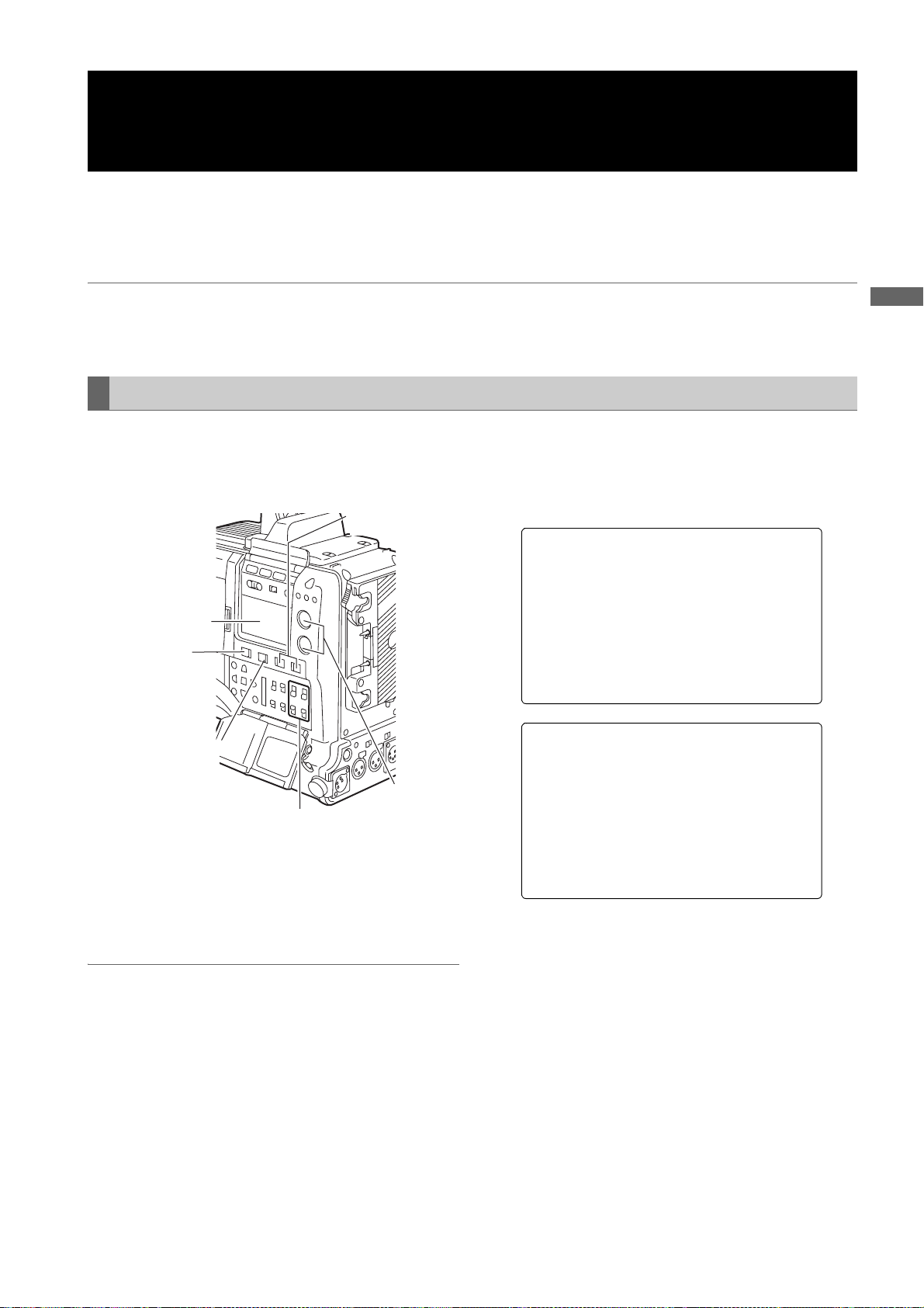
Selecting Audio Input Signals and Adjusting
Recording Levels
AJ-HPX2000 supports independent 4-channel sound recording in any recording format in HD (1080i or 720P) and SD
(DVCPRO50, DVCPRO, or DV with 480i or 576i) modes.
When the AUDIO SELECT CH1/CH2 switch is positioned at [AUTO], the recording levels for Audio Channels 1 and 2 are
automatically adjusted. To manually adjust the recording levels, position the switch at [MAN]. Note that the recording levels
for Audio Channels 3 and 4 are selected through a menu option.
Notes
z Even in HD mode (1080i or 720P), 4-channel sound is recoded on P2 cards.
z When SDI input signals or signals input through the DVCPRO/DV connector are recorded, the settings above are
overridden; audio signals from the SDI IN or DVCPRO/DV connector are always recorded.
Selecting Audio Input Signals
Adjustments and Settings for Recording
The input signals to be recorded on Audio Channels 1, 2,
3, and 4 are selected with the AUDIO IN switch. For more
information, see [Audio (input) Function Section] (page
15).
AUDIO SELECT
CH1/CH2 switch
Display window
MONITOR CH1/3
/ ST / CH2/4
selector switch
MONITOR SELECT
CH1/2 / CH3/4
selector switch
AUDIO
AUDIO IN CH1/CH2/
CH3/CH4 buttons
LEVEL CH1/
CH2 controls
In SD mode (DVCPRO50, DVCPRO, or DV with 480i or
576i), your unit is factory-set to perform no recording on
Audio Channels 3 and 4 in the DVCPRO and DV formats.
To enable four-channel recording, the menu option 25M
REC CH SEL must be set to “4CH”.
Specific audio settings are performed through the <MIC/
AUDIO1> and <MIC/AUDIO2> screens, which are
accessible from the MAIN OPERATION page.
For more information, see [MAIN OPERATION] (page
178).
#
< MIC/AUDIO1 >
FRONT VR CH 1 :OFF
FRONT VR CH 2 :OFF
MIC LOWCUT CH1 :OFF
MIC LOWCUT CH2 :OFF
MIC LOWCUT CH3 :OFF
MIC LOWCUT CH4 :OFF
LIMITER CH1 :OFF
LIMITER CH2 :OFF
AUTO LEVEL CH3 :ON
AUTO LEVEL CH4 :ON
25M REC CH SEL :2CH
TEST TONE :NORMAL
#
< MIC/AUDIO2 >
FRONT MIC P OWER :ON
REAR MIC PO WER :ON
MONITOR SEL ECT :STEREO
FRONT MIC L EVEL : -40dB
REAR MIC CH 1 LEVEL : -60dB
REAR MIC CH 2 LEVEL : -60dB
REAR LINE I N LVL :+4dB
AUDIO OUT L VL :+4dB
HEADROOM :20dB
WIRELESS WA RN :OFF
Notes
z Audio Channels 1 and 2 always receive the signals
selected with the AUDIO IN CH1 and CH2 switches.
z Four-channel-recorded audio signals are SDI-output as
they are.
Adjustments and Settings for Recording : Selecting Audio Input Signals and Adjusting Recording Levels
53
Page 54
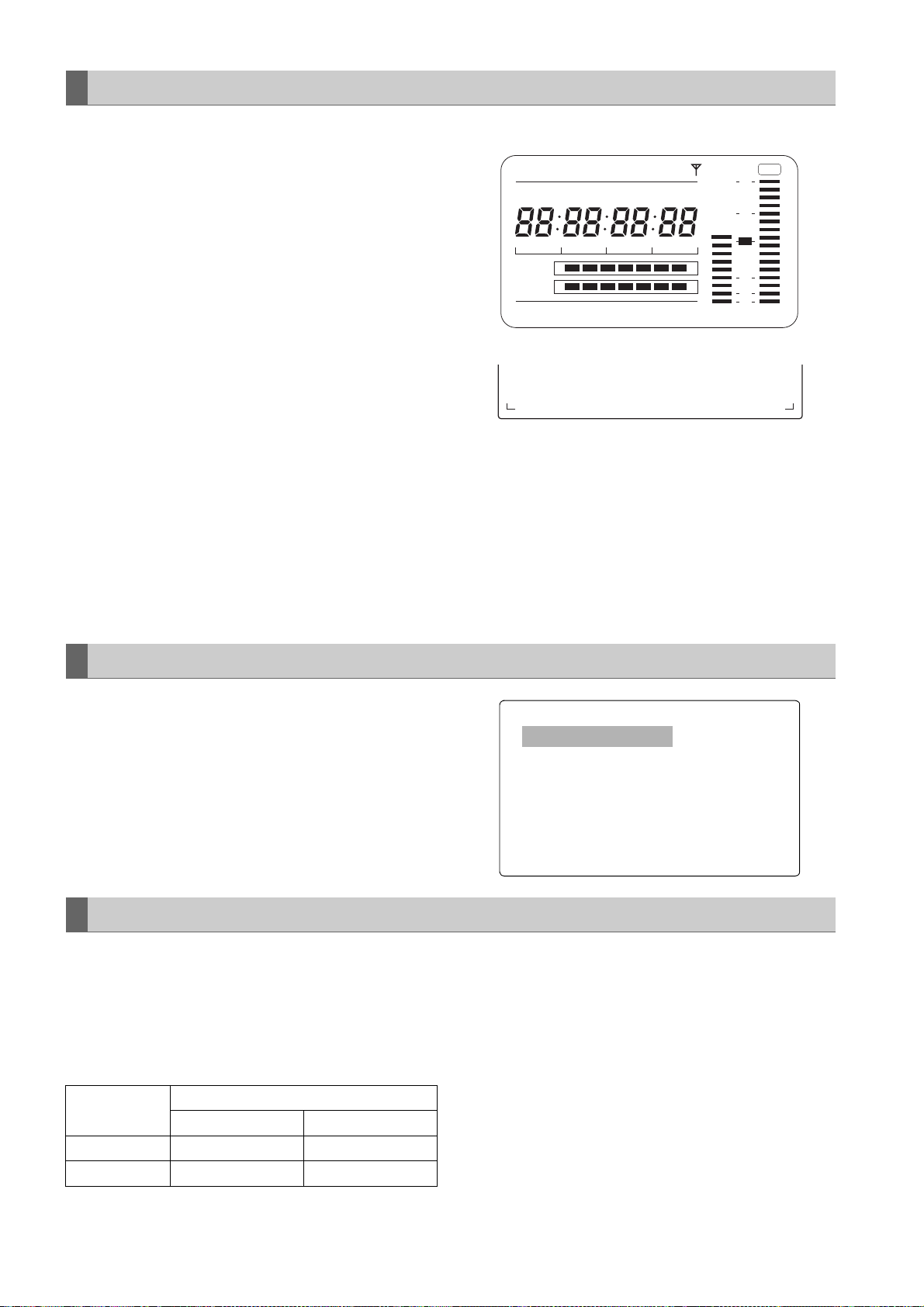
Adjusting Recording Levels
To adjust the recording levels for Audio Channels 1 and 2,
follow the steps below.
1 Position the MONITOR SELECT CH1/2 / CH3/4-
selector switch at CH1/2 so that the audio level meter
on the display window will provide CH1 and CH2
indications. Ensure that the channel indications
displayed in the window are 1 and 2.
Whether to enable or disable the FRONT AUDIO
LEVEL control must be preset through menu options
FRONT VR CH1 and FRONT VR CH2. Note that this
control is factory-disabled.
The menu options are found in the MIC/AUDIO1
screen, which is accessible from the MAIN
OPERATION page.
Audio level meter on the display window
SLAVE HOLD W GPS
NDF
VTCG
CTL
h
MEDIA
BATT
TIME DATE
Y minM
EF
EF
LOOP
Audio level meter in the viewfinder
F:1----
R:2---- ---+
HDV
P-iREC
s
frm
D
OP-SLOT
∫
∫
12
-dB
OVER
0
10
18
30
40
OO
2 Position the AUDIO SELECT CH1/CH2 switch at
[MAN].
3 While checking the audio channel level meter in the
display window or the audio level meter in the
viewfinder, adjust the AUDIO LEVEL CH1/CH2
control.
Note that if the level exceeds the top bar (0 dB), the
When operating the unit without a sound recordist, it is
recommended that the FRONT AUDIO LEVEL control
should be used to adjust the audio level.
In advance, check the level meter in the viewfinder screen
and use the AUDIO LEVEL control to adjust the
appropriate audio channel so that no excessive audio
signals will be admitted.
word OVER illuminates to show that the input level is
excessive. The adjustment made in such a way that
the maximum level will not reach the 0 dB bar.
Selecting Function for the FRONT AUDIO LEVEL Control
This function enables the recording level to be adjusted
using the F.AUDIO LEVEL control.
To select this function, perform menu operations to open
the <MIC/AUDIO> screen from the MAIN OPERATION
page, and set whether to enable or disable the F.AUDIO
LEVEL controls for the system selected as the input
signals using the FRONT VR CH1 and FRONT VR CH2
items.
#
< MIC/AUDIO1 >
FRONT VR CH 1 :OFF
FRONT VR CH 2 :OFF
MIC LOWCUT CH1 :OFF
MIC LOWCUT CH2 :OFF
MIC LOWCUT CH3 :OFF
MIC LOWCUT CH4 :OFF
LIMITER CH1 :OFF
LIMITER CH2 :OFF
AUTO LEVEL CH3 :ON
AUTO LEVEL CH4 :ON
25M REC CH SEL :2CH
TEST TONE :NORMAL
CH3 and CH4 Recording Levels
The following table shows the effects on the recording level
for Audio Channels 3 and 4 that depend on the settings
and input levels specified through the menu options AUTO
LEVEL CH3 and AUTO LEVEL CH4. Note that the
recording level cannot be adjusted manually.
These options are found in the <MIC/AUDIO1> screen,
which is accessible from the MAIN OPERATION page.
AUTO LEVEL
CH3/CH4
ON AGC ON AGC ON
OFF AGC/LIMITER OFF LIMITER ON
Adjustments and Settings for Recording : Selecting Audio Input Signals and Adjusting Recording Levels
54
LINE MIC
Input level
Page 55

Setting Time Data
AJ-HPX2000 supports time codes, user bits, date, and time (real time) data, which are recorded as data for the sub-code
area, VIDEO AUX area, and clip metadata files. It also includes a CTL counter and camera ID.
Description of time data
Time code
The TCG switch can be used to switch between Rec run
and free run.
Free run: The time code always advances even when
the power is turned off. It can be handled as
time. It can be slaved to the time code input
through the TC IN or DVCPRO/DV connector.
Rec run: The time code is recorded as sequential
values regenerated as the time code for a clip
recorded on a P2 card.
User bits
The camera-recorder separately includes two types of user
bits: one (UB) is recorded in the sub-code area and the
other (VITC UB) in the VIDEO AUX area. Each user bits
can be recorded as any of the following: a user defined
value, time, date, same value as the time code, frame rate
information for camera shooting, externally input value
(through the TC IN or DVCPRO/DV connector), and value
regenerated as the user bits recorded in a clip on a P2
card.
The camera-recorder includes only one user defined
value. If user defined values are selected for both the UB
and VITC UB, then the same value is used.
Types of UB can be selected in UB MODE and types of
VITCUB can be selected in VITC UB, respectively.
However, in the following cases, these are fixed to the
frame rate information of the editing machines (editing
software for PCs).
z In 720P mode, both the UB and VITC UB are always
frame rate information.
z For recoding 24P/24PA in 1080i or 480i mode, VITC UB
is fixed to frame rate information.
z In Native mode, VITC UB is fixed to frame rate
information.
CTL counter
The CTL counter will measure total recording time after
resetting in the recording operation. On the other hand,
this value is the count time and sets the start point of a clip
that can be played back. This can be used to find the
current playback position.
Camera ID
The camera ID can be set with 10 characters
which can be superimposed on the color bar video. It can
be also superimposed along with date and time data.
a3 lines,
Adjustments and Settings for Recording
Date and time (real time)
The built-in clock maintains the date and time. When the
GPS unit AJ-GPS910G is installed, the built-in clock is
corrected with accurate date and time information from the
GPS. This clock is used to store the date and time while
the power is turned off and as the time for the user bits and
date data, as well as the reference for file generation times
during clip recording, which determine the sorting order of
thumbnails and the order of playback. It is also used to
generate clip metadata and UMIDs (Unique Material
Identifiers) in the VIDEO AUX area.
Adjustments and Settings for Recording : Setting Time Data
55
Page 56

Recording time code and user bits
The number of frames for TC varies with the settings for the input signal, system mode, and camera mode as follows.
No. of
REC
SIGNAL
CAM
SDI*1 or
VIDEO
1394
SYSTEM
MODE
1080-59.94i
1080-50i
720-59.94P
720-50P
480-59.94i
576-50i
1080-59.94i
480-59.94i
720-59.94P
1080-50i
576-50i
720-50P
1080-59.94i
720-59.94P
480-59.94i
1080-50i
720-50P
576-50i
Recording
frame
10
MODE*
60i,
30P (Over 60i)
24P (Over 60i)
24PA (Over 60i)
30PN (Native)
24PN (Native)
50i,
25P (Over 50i)
25PN (Native)
60P,
30P (Over 60P)
24P (Over 60P)
30PN (Native)
24PN (Native)
50P,
25P (Over 50P)
25PN (Native)
60i
30P (Over 60i)
24P (Over 60i)
24PA (Over 60i)
50i,
50P (Over 50i)
j
j
(Natives of
AVC-Intra and
DVC PRO HD
are not
selectable.)
TC in subcode area
As per the TC
4
MODE*
Always nondrop frame*
As per the TC
MODE*
Always nondrop frame*
As per the TC
MODE*
Always nondrop frame*
As per the TC
MODE*
Always nondrop frame*
As per the TC
MODE*
Always nondrop frame*
As per the TC
MODE*
As per the TC
MODE*
j*
j*
j*
j
j
5
4
5
4
4
5
4
5
4
4
5
4
4
4
*
4
2
*
TC in VIDEO
AUX area
(VITC)
As per the TC
4
MODE*
Always nondrop frame*
As per the TC
MODE*
Always nondrop frame*
As per the TC
MODE*
Always nondrop frame*
As per the TC
MODE*
Always nondrop frame*
As per the TC
MODE*
Always nondrop frame*
As per the TC
MODE*
Regardless of the
setting, TC in the
VIDEO AUX area
input through the
DVC PRO /DV
connector is
recorded.
j*
j*
j*
j
5
4
5
4
4
5
4
5
4
4
5
4
4
4
*
frames of
TC during
recording
and
presetting
30
24
25 25
30
24
25 25
30 30
25 25
30 30
25 25 25
30 30
25 25
No. of
frames of
the output
TC
30
30
No. of frames
of the
displayed TC
30/24 switchable
Recording:
24 fixed
Playback:
30/24
switchable
25
30/24 switchable
Recording:
24 fixed
Playback:
30/24
switchable
25
30/24 switchable
25
30/24 switchable
30/24 switchable
25
UB in sub-
code area
As per the UB
6
MODE*
As per the UB
9
MODE
*6*
As per the UB
6
MODE
*
As per the UB
9
MODE
*6*
Always frame
rate
information
Always frame
rate
information
Always frame
rate
information
Always frame
rate
information
As per the UB
MODE
As per the UB
MODE
As per the UB
MODE
Always frame
rate
information
As per the UB
MODE
Always frame
rate
information
As per the UB
MODE
3
*
*3 *
3
*
*3 *
6
*
6
*
6
*
3
*
6
*
3
*
7
*
UB in VIDEO
AUX area
(VITC UB)
As per the VITC
UB MODE
Always frame
rate
information*
Always frame
rate
information
As per the VITC
UB MODE
Always frame
rate
information
Always frame
rate
information
Always frame
rate
9
information
Always frame
rate
information
Always frame
rate
9
information
As per the VITC
UB MODE
Always frame
rate
information
As per the VITC
UB MODE
As per the VITC
UB MODE
Always frame
rate
information
As per the VITC
UB MODE
Always frame
rate
information
Regardless of the
setting, TC in the
UB area input
through the
DVCPRO/DV
connector is
recorded.
3
8
*
8
*
3
*
8
*
3
*
8
*
3
*
3
*
3
*
Adjustments and Settings for Recording : Setting Time Data
56
Page 57

*1 It will not be slaved to a TC or UB value that is input in the SDI IN connector.
*2 Can be slaved to values input through the DVCPRO/DV connector but not to the TC for TC IN connector.
*3 If the option menu FRAME RATE UB is set to MENU, then recording is performed as per the UB or VITC UB mode. If
this is the case, however, edit tools (e.g. PC edit software) cannot record the required information.
*4 For free run, the time code is slaved to the time code input through the TC IN connector.
*5 For free run, the time code is slaved to the time code input through the TC IN connector if it is a non-drop frame.
*6 When the option UB MODE is set to EXT, then the bits are slaved to the user bits input through the TC IN connector.
*7 If the option UB MODE is set to EXT, then the bits are slaved to the user bits input through the DVCPRO/DV
connector.
Regardless of the menu settings, frame rate information is always recorded. During playback, the information is output
*8
after being converted into pull-down frame rate information.
*9 When the UB MODE is set to [FRM.RATE], the pull-down frame rate information read out from the UB in the VAUX area
is output during playback.
*10 For details on this item, refer to [Recording formats and output connector signal formats] (page 43)
Setting of the user bits
Adjustments and Settings for Recording
The user bits (UB) to be recorded in the sub-code area are
selected through the menu option UB MODE. The user
bits (VITC UB) to be recorded in the VIDEO AUX area are
selected through the menu option VITC UB MODE.
USER (UB MODE only)
The included user value is recorded. A user value is
input through the display window. For more information
about how to input a user value, see[
value
] (page 57). The recorded user value is retained
even if the power is turned off.
TIME
The time kept by the built-in clock is recorded.
DATE
The hour digits for date and time kept by the built-in
clock are recorded.
EXT (UB MODE only)
The user bits value input through the TC IN connector
is recorded. When the menu option REC SIGNAL is
set to 1394, then the value is slaved to the user bits
value from the DVCPRO/DV connector. The included
user’s value will also be this input value.
TCG
The time code value is recorded.
FRM.RATE
The frame rate information for camera shooting is
recorded. For more information, see [
mation recorded in user bits
REGEN
The user bits last recorded on the current target P2
card is read and recorded as is.
USER/EXT
(VITC UB MODE only)
The included user’s value is recorded as the user bits
for the VIDEO AUX area. It is the same value as the
user bits indicated when the option UB MODE is set to
“USER” or “EXT”.
] (page 58).
Inputting a user
Frame rate infor-
Inputting a user value
HOLD switch
DISPLAY switch
Display
window
TCG switch
CURSOR and SET buttons
1 Position the DISPLAY switch at [UB].
2 Position the TCG switch at [SET].
When the left digit starts blinking you can change the
value.
3 Use CURSOR buttons to set the user bits.
! button:Shifts the target (blinking) digit to the right.
" button:Shifts the target (blinking) digit to the left.
# button:Advances the blinking number by one digit.
$ button:Winds back the blinking number by one digit.
4 Position the TCG at [F-RUN] or [R-RUN].
5 Go to the <TC/UB> screen from the MAIN
OPERATION page, and set the menu option UB
MODE to “USER”.
Notes
z When the TCG switch is positioned at [SET],
thumbnails cannot be manipulated.
z To confirm VICT UB, press the HOLD switch to
display VTCG on the display window.
Adjustments and Settings for Recording : Setting Time Data
57
Page 58

Retaining the user bits
/
For 1080i or 480i/576i
The data set for the user bits are automatically saved and
retained even if the camera-recorder is turned off.
Frame rate information recorded in user bits
If video information to be recorded based on the frame rate
set through the menu option CAMERA MODE is recorded
in the user bits, it can be edited with editing tools (e.g. PC
editing software). In 1080i and SD mode, the frame rate
information for the user bits recorded in the VIDEO AUX
area are used. In 720P mode, the video information is also
recorded in the sub-code area because the frame rate
information for the user bits recorded in the sub-code area
is also used.
Frame rate information
The frame rate and video pull-down menu are linked to the
time code and user bits as follows:
__
Fixed value
Checking
information for the 6
digits at right.
Sequence No.
24P, 24PA: 0 to 4
In all other modes
: Fixed at F
_
Media management information
z Updated frame information
Effective frame
z REC START/STOP mark
Camera shooting mode
60i: 600
60P: 608
30P: 308
24P: 248
24PA: 24C
50i: 502
50P: 50A
25P: 25A
Frame rate: 24P Over 60i (2:3)
Starting field for the
Time code frame digit
00 01 02 03 04 05 06
Image
Sequence No.
0 1 2 3 4 0 1
Updated frame information
10 10 01 01 00 10 10
updated frame
• • •
23 24 25 26 27 28 29
• • •
Co De Do DeAo Ae BoBe Bo CeCo DeDo DeAo AeBo Be BoCe CoDe DoDe Ao AeBo Be
• • •
3 4 0 1 2 3 4
• • •
01 00 10 10 01 01 00
Frame rate: 24PA Over 60i (2:3:3:2)
Time code frame digit
00 01 02 03 04 05 06
Image
Sequence No.
0 1 2 3 4 0 1
Updated frame information
10 10 01 00 10 10 10
• • •
23 24 25 26 27 28 29
• • •
Co Ce Do DeAo Ae BoBe Bo CeCo CeDo DeAo AeBo Be BoCe CoCe DoDe Ao AeBo Be
• • •
3 4 0 1 2 3 4
• • •
00 10 10 10 01 00 10
Frame rate: 30P Over 60i (2:2)
25P Over 50i (2:2)
Time code frame digit
00 01 02
Image
Ao AeBo Be CoCe
Updated frame information
10 10 10
• • •
• • •
• • •
Adjustments and Settings for Recording : Setting Time Data
58
Page 59

For 720P
_
Frame rate: 24P Over 60P (2:3)
Time code frame digit
00 01 02 03 04 05 06
Image
Effective frame information
10 10 01 01 00 10 10
• • •
• • •
• • •
Effective frame
23 24 25 26 27 28 29
C DDD AABBB CCDDDAABBB CCDDD AABB
01 00 10 10 01 01 00
Frame rate: 30P Over 60P (2:2)
25P Over 50P (2:2)
Time code frame digit
00 01 02
Image
AABBC C
Effective frame information
10 10 10
• • •
• • •
• • •
The frame rate information of user bits in Native recording is
as follows.
__
)&
_
Adjustments and Settings for Recording
Media management
Fixed value
Verification
information for the
6 digits to the right
information
REC START/STOP mark
Camera recording mode
24PN: 24C
30PN: 308
25PN: 25A
Note
During playback of clips recorded in Native recording frame
rate information of user bits is converted according to the
image pull down and then output.
Example:
Recording
__
)&
Playback
__
_
# indicates sequence Nos. 0 to 4.
Adjustments and Settings for Recording : Setting Time Data
59
Page 60
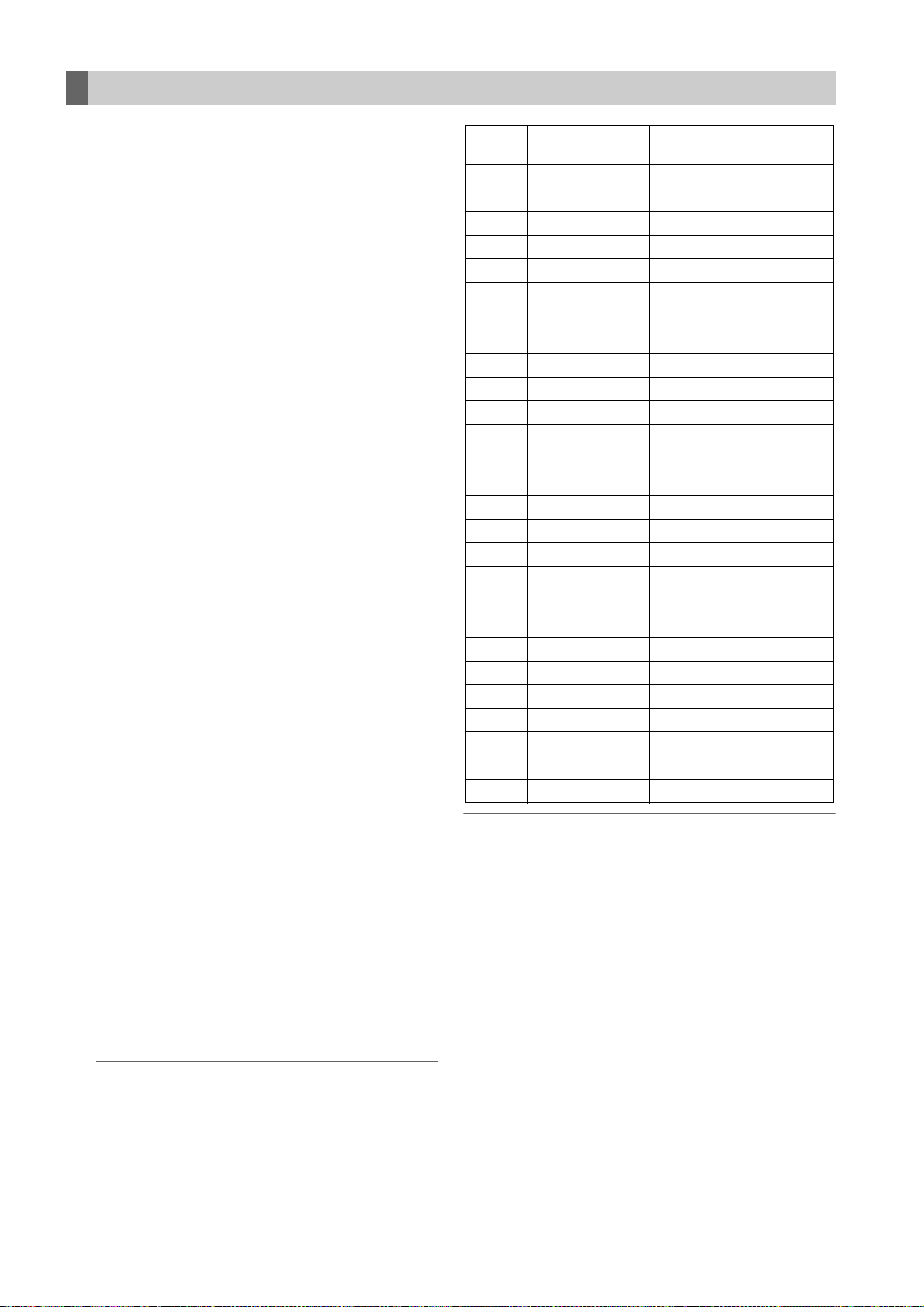
Setting the Internal Clock’s Date and Time
1 Position the DISPLAY switch at [UB].
2 Press the HOLD button to display a date in the display
window.
3 Position the TCG switch at [SET].
4 Use the CURSOR and SET buttons to set the year,
month and day (Y/M/D).
Note that any later than 2030 cannot be set.
! button: Shifts the target (blinking) digit to the
right.
" button: Shifts the target (blinking) digit to the left.
# button: Advances the blinking number by one
digit.
$ button: Winds back the blinking number by one
digit.
5 Press the HOLD button to display a time in the display
window.
6 Use the CURSOR buttons to set the hour, minute and
second (h/min/s).
7 Position the TCG switch at [F-RUN] or [R-RUN]. The
internal clock starts at the moment the switch position
is changed.
8 Press the HOLD button to display a time zone (time
difference between local time and Greenwich Mean
Time) in the display window.
9 Position the TCG switch at [SET].
10
Use the # and $ buttons to set the desired hours
and minutes ahead of (no sign) or behind (– sign) the
Greenwich Mean Time).
Example: If the local time is five hours behind
Greenwich Mean Time,
set the time zone to “5:00 –”.
The time zone is always recorded, together with the
date and time, as metadata.
See the table at right to set the time zone according to
your local time.
11
Position the TCG switch at [F-RUN] or [R-RUN] to
accept the time zone.
Notes
z When using the camera-recorder for the first time,
be sure to perform this setting beforehand. Do not
change the setting during use of the camerarecorder.
z When the TCG switch is positioned at [SET],
thumbnails cannot be manipulated.
Time
difference
00:00
+ 00:30
+ 01:00
+ 01:30
+ 02:00
+ 02:30
+ 03:00
+ 03:30
+ 04:00
+ 04:30
+ 05:00
+ 05:30
+ 06:00
+ 06:30
+ 07:00
+ 07:30
+ 08:00
+ 08:30
+ 09:00
+ 09:30
+ 10:00
+ 10:30
+ 11:00
+ 11:30
+ 12:00
+ 12:45
+ 13:00
Area
Greenwich –
Central Europe –
Eastern Europe –
Moscow –
Tehra n –
Abu Dhabi –
Kabul –
Islamabad –
Bombay –
Dacca –
Rangoon –
Bangkok –
Beijing –
Tokyo –
Darwin –
Guam –
Lord Howe Island –
Solomon Islands –
Norfolk Island –
New Zealand
Chatham Islands
Time
difference
12:00
–
11:30
11:00
–
10:30
10:00
–
09:30
09:00
08:30
08:00
07:30
07:00
06:30
06:00
05:30
05:00
–
04:30
04:00
–
03:30
03:00
02:30
02:00
01:30
01:00
00:30
Area
Kwajalein
Midway Island
Hawaii
Marquesas Islands
Alaska
Los Angeles
Denver
Chicago
New York
Halifax
Newfoundland Island
Buenos Aires
Mid-Atlantic
Azores Islands
Notes
z In Step 4, if the TCG switch is positioned at [F-RUN] or
[R-RUN], this also activate the internal clock.
To cancel date, time and time zone settings in process,
hold down the SET button and position the TCG switch
at [F-RUN] or [R-RUN].
z
Clock accuracy fluctuates between about ± 30 seconds per
month when the power is turned off. If more accurate
timekeeping is required, check the time when the power is
turned on and, if necessary, reset the clock.
When the GPS unit AJ-GPS910G is installed, and if it
successfully receives time information, the internal clock
keeps accurate (local) time based on the received time
(Greenwich Mean Time) and the time zone. If the date and
time differ from the actual local time, the time zone may not
be set correctly. Check again, to see if the time zone is set
correctly. (The date and time need not be set again.)
z
The built-in clock operates for several years on a lithium
battery built into the camera-recorder. When the lithium
battery is exhausted, the viewfinder indicates the message
“BACKUP BATT EMPTY” when the power is turned on. For
more information, see [Maintenance] (page 140).
Adjustments and Settings for Recording : Setting Time Data
60
Page 61

Setting the Time Code
1 Position the DISPLAY switch at [TC].
2 Position the TCG switch at [SET].
3 Set the menu option TC MODE to “DF” or “NDF”. “DF”
steps the time code in drop frame mode, and “NDF”
steps it in non-drop frame mode. However, the
camera always operates in “NDF” for 24P, 24PA and
24PN (Native) modes.
The menu option TC MODE can be found in the <TC/
UB> screen, which is accessible from the MAIN
OPERATION page.
Note
Switching between DF and NDF is operative only
when the system frequency of the camera-recorder is
set to 59.94 Hz.
4 Use the CURSOR buttons to set the time code.
The time code setting range extends from
00:00:00:00 to 23:59:59:29 (59.94 Hz), 23:59:59:23
(24PN) or to 23:59:59:24 (50 Hz).
! button:Shifts the target (blinking) digit to the right.
" button:Shifts the target (blinking) digit to the left.
# button:Advances the blinking number by one digit.
$ button:Winds back the blinking number by one digit.
5 Change the position of the TCG switch.
[F-RUN] steps the time code in free run mode, and [R-
RUN] set it in recording run mode.
Notes
z When the unit is in the 24P or 24PA mode, time
code settings are adjusted to the five-frame unit.
For 24PN (Native) mode, it is adjusted for counting
by the four-frame unit. For 30PN UN (Native) of
720P, it is adjusted to even numbers. In the 25PN
(Native) mode of 720P, [Sec + Frame] is adjusted to
even numbers. The time code cannot be set when
recording in the 24P, 24PA, and 24PN (Native)
formats.
z When the TCG switch is positioned at [SET],
thumbnails cannot be manipulated.
Regeneration function using REC REVIEW
If the menu option FIRST REC TC is set to PRESET, if the
time code has been set or reset, or if the time code has
been switched from free run to Rec run, it is possible to
regenerate the time code as the last time code of a clip
recorded on the P2 card.
This action requires you to preset the RET SW menu
option on the SW MODE screen to R. REVIEW and the
REC REVIEW REGEN menu option on the TC/UB screen
to ON.
1 Make sure the P2 card to record the data. To
regenerate the time code of the last recorded clip
when more than one P2 card is inserted, press the
Thumbnail button to open the thumbnail screen.
2 Be sure a P2 card is inserted for recording the clip
displayed at the end of the screen, and then switch
the slot with the USER button assigned the SLOT
SEL function so that data will be recorded on the P2
card.
3 Press the RET button on the lens. The message “TC
REGEN” is displayed in the viewfinder. During the
next recording, the time code of the last recorded clip
on the card will be regenerated.
Notes
z When a card with recorded data is changed, the
time code of the last recorded clip on the changed
P2 card will be regenerated.
z This function is disabled during recording or free-
run.
Time code function during battery replacement
Even during battery replacement, the backup mechanism
functions, allowing the camera-recorder to operate
continuously.
If SYSTEM MODE is changed, a free-run time code may
shift. After turning on the power again, confirm the time
code and reset if necessary.
Adjustments and Settings for Recording
Regeneration of Time Code
When the TGC switch is positioned to R-RUN, the time
code recorded on the last frame of the last recorded clip
(with the latest recording date) on the P2 card is read, and
this time code can be used again.
When the menu option FIRST REC TC is set to REGEN
and a P2 card is removed or inserted or the target
recording card is changed with the USER button for the
SLOT SEL function, the same time code is added to the
last recorded clip on the target P2 card. When there is no
recorded clip, the time code is recorded on the new
recording target P2 card, from the value generated by the
TC generator built into the camera-recorder.
The menu option FIRST TC REC can be found in the <TC/
UB> screen, which is accessible from the MAIN
OPERATION page.
Note
When the POWER switch has been switched ON # OFF
# ON, the backup accuracy of the time code in free run
mode is about ±2 frames.
Adjustments and Settings for Recording : Setting Time Data
61
Page 62
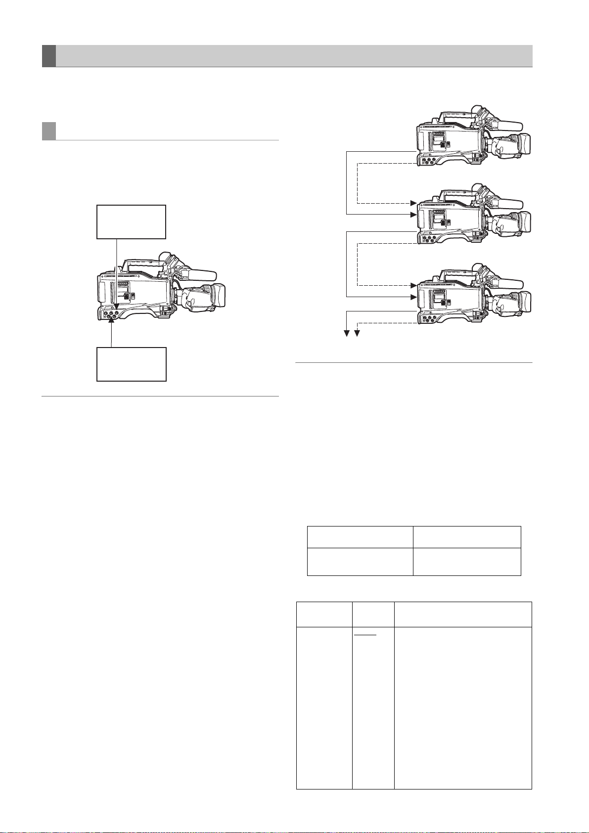
Externally Locking the Time Code
The unit’s internal time code generator can be locked to an
external generator. In addition, the external time code
generator can be locked to the unit’s internal generator.
Example of connections for external locking
As the figure shows, connect both the reference video
signal and reference time code.
Example 1: When locking onto an external signal
Reference time
code
TC IN
GENLOCK IN
Reference video
signal
Note
In place of the HD Y reference signal, composite video
signals can be input as the reference video signal.
Example 2: When connecting a multiple number of units
and using one of them as the reference unit
MON OUT or
VIDEO OUT
(VBS)
MON OUT or
VIDEO OUT
(VBS)
MON OUT or
VIDEO OUT
(VBS)
To the next camera
TC OUT
Reference unit
TC IN
GENLOCK IN
TC OUT
TC IN
GENLOCK IN
TC OUT
Note
The system can be configured with multiple units by
opening the <GENLOCK> screen from the SYSTEM
SETTING page and setting the GL PHASE item to the
connector using menu operations.
The phase of the time code can correspond to either the
HDY output signals of the MON OUT connector or VBS
output signals of the VIDEO OUT and MON OUT
connector.
However, the same value should commonly be set to the
GL PHASE for all cameras. If different values coexist in the
system, the shooting timing may not correspond to each
other.
Adjustments and Settings for Recording : Setting Time Data
62
Reference video signal Setting of GL PHASE
MON OUT (VBS) or
VIDEO OUT (VBS)
COMPOSIT
Setting of GL PHASE
Item
GL PHASE HD SDI
Varia ble
range
COMPOSIT
Remarks
For selecting the output signals that
lock phases to the signals that are
input in the GENLOCK IN connector.
HD SDI:
For locking the HD SDI signals to
the GENLOCK input.
For the down converter output
signals, the start position of the
video delays by about 90 lines.
COMPOSIT:
For locking the down converter
output signals to the GENLOCK
input.
For the HD SDI output signals, the
start position of the video gains by
about 90 lines.
Page 63

In the unit, there is a video signal delay in the camera,
which is required or the process of converting video
images taken with the image-shooting element from the
progressive signals to the interlace signals. Since time is
required for making the 2:3 pull-down from the 24P frame,
there is a video signal delay in the camera. When
recording from a device that can record images without a
delay and the unit is connected in parallel, it is necessary
to synchronize the time code. To set this timing, open the
<TC UB> screen from the VTR MENU page and set it in
the TC VIDEO SYNCRO item.
Set by referring to the connection example.
Setting of the TC VIDEO SYNCRO item
Example 4:
When the unit and an external device are locked to the
external time code generator and when several units
of the camera are connected in a cascade
configuration.
Reference video signal
External time code generator
TCG
TC OUT
Device that records images without a delay
TC IN
DAT
Adjustments and Settings for Recording
Item
TC VIDEO
SYNCRO
Var iab le
range
0
1
2
3
Remarks
For setting to correct the time code
according to the delay of video
signals.
0: Do not correct.
1: To delay the time code to be input
according to the timing of the
video images.
2: To forward the time code to be
output according to the timing of
the video images.
3: To delay the time code to be input
and forward the time code to be
output, respectively, according to
the timing of the video images.
Example 3:
When the unit and an external device are locked to the
external time code generator, which is connected
externally, and when simultaneous recording is made
by using the TC OUT output signals.
Reference video signal
External time code generator
TCG
TC OUT
Device that records images without a
delay
TC IN
DAT
TC IN
GENLOCK IN
TC OUT
TC IN
GENLOCK IN
TC OUT
TC IN
GENLOCK IN
TC OUT
AJ-HPX2000
AJ-HPX2000
AJ-HPX2000
1st unit
Settings of the TC
VIDEO SYNCRO
item: 1
2nd unit and later
Settings of the TC
VIDEO SYNCRO
item: 0
Settings of the TC
VIDEO SYNCRO
item: 0
GENLOCK IN
MON OUT
VIDEO OUT
VIDEO IN
SDI IN
HD SDI IN
REF IN
TC IN
or
AJ-HPX2000
TC OUT
VTR etc.
TC IN
Settings of the TC
VIDEO SYNCRO
item: 1
Adjustments and Settings for Recording : Setting Time Data
63
Page 64

Example 5:
When an external device is locked to the time code
generator of the unit.
Reference video signal
To be connected if necessary
TCG
TC OUT
Example 6:
When an external device is locked to the time code
generator of camera-recorder, which is connected in a
cascade configuration.
Reference video signal
To be connected if necessary
TCG
TC OUT
TC IN
GENLOCK IN
TC OUT
TC IN
AJ-HPX2000
Settings of the TC
VIDEO SYNCRO
item: 3
A device that synchronizes with the TC
IN input and capable to record without
delay (DAT etc.)
DAT
TC IN
GENLOCK IN
TC OUT
TC IN
GENLOCK IN
TC OUT
TC IN
GENLOCK IN
TC OUT
TC IN
AJ-HPX2000
1st unit
Settings of the TC
VIDEO SYNCRO
item: 1
AJ-HPX2000
From the 2nd unit to the (n-1)-th unit
Settings of the TC
VIDEO SYNCRO
item: 0
AJ-HPX2000
n-th unit
Settings of the TC
VIDEO SYNCRO
item: 2
A device that synchronizes with the TC IN
input and capable to record without delay
(such as DAT or a camera recorder)
DAT
Adjustments and Settings for Recording : Setting Time Data
64
Page 65

To externally lock the time code Setting the user bits when the time code is
Follow the steps below.
1 Turn on the POWER switch.
2 Position the TCG switch at [F-RUN].
3 Position the DISPLAY switch at [TC].
4 Set the menu option GENLOCK to “EXT”.
This option can be found in the <GENLOCK> screen,
which is accessible from the SYSTEM SETTING
page.
5 Supply a phase-relationship reference time code (that
conforms to the time code requirements) and
reference video signals to the TC IN and GENLOCK
IN connectors, respectively.
Now the built-in time code generator is locked with the
reference time code.
From about 10 seconds after locking the time code
generator stays locked even if the supply of external
reference time code is discontinued.
externally locked
When the TCG switch is positioned to F-RUN, only the
time code is locked to an external time code. To lock the
user bits to an externally input value, the UB MODE and
VITC UB MODE menu options must be set to EXT and
USER/EXIT, respectively.
The menu option UB MODE and VITC UB MODE can be
found in the <TC/UB> screen, which is accessible from the
MAIN OPERATION page.
To unlock the externally locked time code
Discontinue external time code supply, then position the
TCG switch at [R-RUN].
Cautions in switching the power source from
battery to external power supply
Connect the DC IN socket with the external power supply
before removing the battery pack, in order to keep the time
code generator energised. If the battery pack is removed
first, there is no guarantee that the time code will stay
externally locked.
Adjustments and Settings for Recording
Notes
z When the time code generator is externally locked, the
time code instantly becomes locked with the external
time code, and the counter displays the external time
code value. Do not put the unit in recording mode before
the sync generator stabilises.
z Be sure to enter the non-drop-frame time code to
externally lock the time code in the 24P, 24PA or 24PN
(Native) mode. Externally locking the drop-frame time
code is not permitted.
Video quality may be degraded momentarily while
externally locking to adjust the 5-frame cycle. This is not
abnormal.
z While recording data in the 24P, 24PA, or Native modes,
it is impossible to lock the time code externally. Lock it
before recording.
When the unit PRE REC MODE is set to [ON] in these
modes, corrupt images or stopped time codes may be
recorded if the time code is switched from REC RUN to
FREE RUN immediately before recording or when using
slave lock.
z When “1394” is selected for the menu option REC
SIGNAL, it is not possible to synchronize with the time
code entered via TC IN connector.
The menu option REC SIGNAL is found in the SYSTEM
MODE screen on the SYSTEM SETTING page.
External synchronisation of the camera when the
time code is externally locked
When the time code is externally locked, the reference
video signals input through the GENLOCK IN connector
gen-lock the camera.
Notes
z To externally lock the unit, as the master device, with
more than one unit, the mode must be the same as that
of the camera. Note that in a system using both
interlaced and progressive scanning, there may be
breaks in the video and time code.
z When using the MON OUT or VIDEO OUT connector to
output reference signals, position the OUTPUT SEL
switch on the side panel at [CAM].
Superimpose of time codes
To display the time code in the viewfinder or the LCD monitor
when recording or during playback, set TC in <VF
INDICATOR2> to [TCG], [TCR], or [TCG/TCR].
To display the time code indication on the MONITOR OUT or
VIDEO OUT outputs, set MONI OUT CHARA in <OUTPUT
SEL> to [ON] and the VIDEO OUT CHARACTER switch to
[ON].
To display the time code while the color bar is displayed, set
TC ON COLOR BAR in <VF INDICATOR2> to [ON].
Adjustments and Settings for Recording : Setting Time Data
65
Page 66

Providing an ID to the Camera
The camera ID is specified through the <CAMERA ID>
screen.
The ID can include up to 10 alphanumeric characters,
symbols, and/or spaces.
Note
When the settings menu is displayed, outputting color bar
signals does not indicate the camera ID.
1 Go to the <CAMERA ID> screen from the CAM
OPERATION page.
#
< CAMERA ID >
ID1 : ABCDE FGHIJ
ID2 : ABCDE FGHIJ
ID3 : ABCDE FGHIJ
2 Turn the JOG dial button to move the cursor to options
[ID1:] - [ID3:].
9 To exit the menu, press the MENU button.
Notes
z When the menu option CAMERA ID is set to “BAR”,
the camera ID is recorded together with color bar
signals.
This menu option is accessible from the <VF
INDICATOR1> screen, which is accessible from the
VF page.
z The ID POSITION menu option can be used to
select a position where the camera ID is
superimposed on the color bar. The ID POSITION
option can be accessed through the VF
INDICATOR 1 screen on the VF page.
z When the TIME/DATE menu option is set to ON, the
camera ID along with the data and time information
are superimposed on the color bar. The TIME/DATE
option can be accessed through the VF
INDICATOR 1 screen on the VF page.
3 Press the JOG dial button. The cursor moves to the
ID entry area, allowing you to enter an ID.
4 Turn the JOG dial button until a desired character
appears. The characters that appear are switched in
the following order:
Space:
Ð
Alphabetical characters: A to Z
Ð
Numerals: 0 to 9
Ð
Symbols: ', >, <, /, -
5 Press the JOG dial button to accept a desired
character.
6 Turn the JOG dial button to move cursor to the next
digit (clockwise), and repeat Steps
characters.
To change an input character, turn the JOG dial
button to move the arrow (cursor) to the appropriate
character and carry out steps
4 - 5 to set
4 and 5.
7 When all the characters are set, turn the JOG dial
button to move the cursor to [:].
8 Pressing the JOG dial button brings the cursor back
to the options [ID1:] - [ID3:].
Adjustments and Settings for Recording : Setting Time Data
66
Page 67

Setting UMID Information
The unit supports UMID metadata. You need to specify as
UMID information the country where you live (using up to
three characters), organisation or company (up to four
characters) and user name (up to four characters). For the
country name, you must use abbreviations prescribed in
1
the ISO3166 Country Code*
Here are some examples of the correct method for
specifying a user name:
*1 Examples: China CHN
U.S.A. USA
Canada CAN
Japan JPN
< UMID SET/IN FO >
--OWNER- COUNTRY :***
ORGANIZATION :****
#
USER :****
**DEVICE NOD E**
.
8 To exit the menu, press the MENU button.
Adjustments and Settings for Recording
1 Go to the <UMID SET/ INFO> screen from the MAIN
OPERATION page.
2 Turn the JOG dial button to move the cursor to the
option [USER].
3 Press the JOG dial button. The cursor moves to the
user entry area, allowing you to enter a user name.
4 Turn the JOG dial button until a desired character
appears. The characters appear in the following
order:
Space:
Ð
Alphabetical characters: A to Z
Ð
Numerals: 0 to 9
Ð
Symbols: ', >, <, /, -
Note
The COUNTRY entry can only include alphabetical
characters and spaces.
5 Press the JOG dial button to accept a desired
character.
6 Turn the JOG dial button to move the cursor to the
next digit (clockwise), and repeat Steps
characters.
To change an input character, go back to step
4 to 5 to set
3.
7 When the last character is set, press the JOG dial
button to bring the cursor back to the option [USER].
Adjustments and Settings for Recording : Setting Time Data
67
Page 68
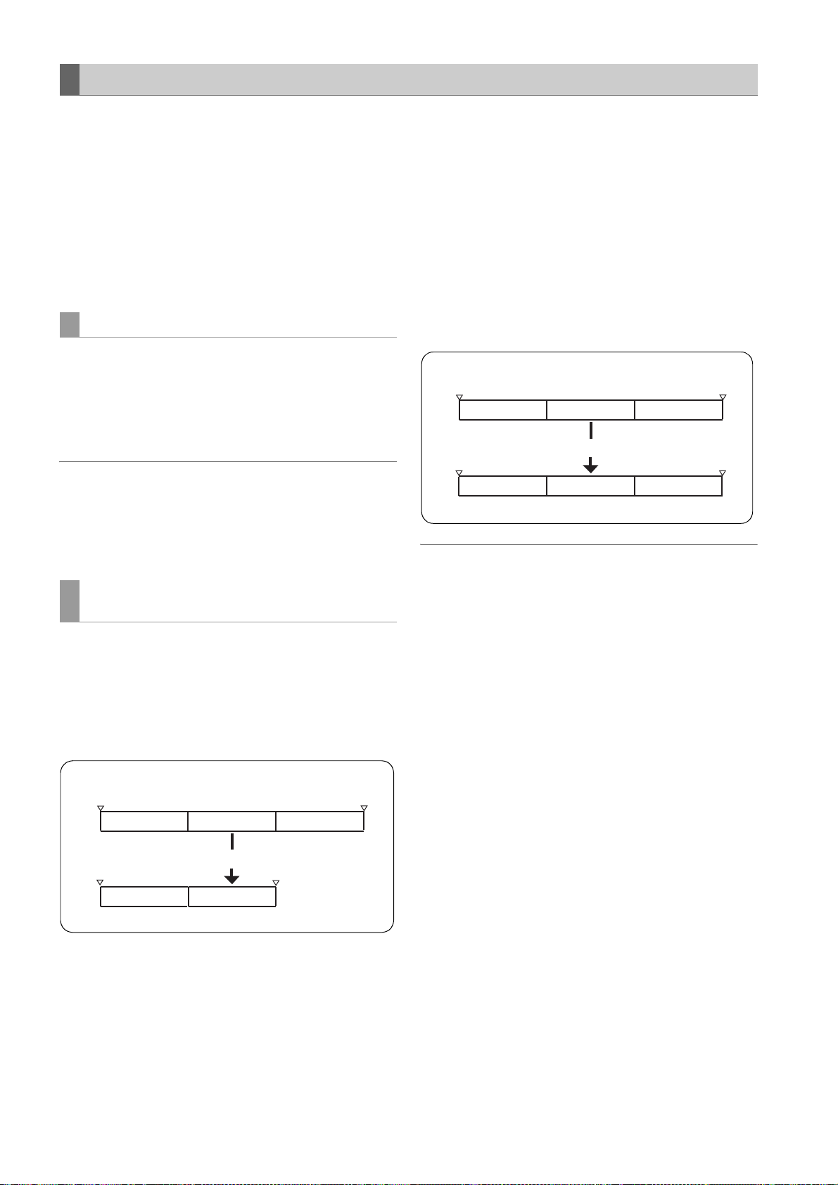
CTL Count Setting and Display
–
By setting the DISPLAY switch to “CTL”, CTL count is
displayed on the time count indication of the LCD display
window.
The CTL count is displayed in ±12 hours with non-dropframe.
The playback order of clips recorded on a P2 card is not
linear as for VTRs. It is organized according to thumbnail
operations or exchanging P2 cards, and the priority of
recorded clips will be altered. Therefore, different CTL
counts are displayed for recording mode and playback
mode, respectively.
CTL count for recording mode (recording CTL)
Recording CTL count is displayed during recording mode
(REC, REC/PAUSE, STOP and REC REVIEW), and the
count continues from the end point of the previous
recording. Recording CTL count is retained even if the
power is turned off. When the power is next turned on, the
count continues from the previous value.
Notes
z If the RESET button is pressed while the recording CTL
count is being displayed, only the recording CTL count is
reset. Note that reset is disabled during the REC
REVIEW operation.
z 24 frames are counted in the 24PN (Native) mode.
CTL count for the playback mode
(playback CTL)
During playback mode (PLAY, FF, REW, PLAY/PAUSE),
playback CTL count is displayed.
Whenever the playback order of clips is altered (clips are
sorted by shooting dates), previous playback CTL count is
disabled. The first frame of the first clip is used as a
reference value for recalculation, and the new playback
CTL count is displayed.
The playback order of clips is altered when either of the
following occurs:
z Clips are deleted, copied or restored, or the P2 card is
formatted.
z The thumbnail display is switched (for more information,
see [Switching the Thumbnail Display] (page 113)).
z A P2 card is inserted or removed.
The reference value (value of the first frame of the first clip)
is changed when either of the following occurs:
z The power is turned on, the first frame becomes 0.
z When the playback CTL count is reset, the current
playback position is set as 0, and the previous reference
value becomes a negative value.
Example:
First frame
00:00:00:00
First frame
00:03:00:00
Clip 1
00:01:00:00 00:02:00:00 00:03:00:00
Clip 1
–00:02:00:00 –00:01:00:00
Clip 2
Reset
Clip 2
Current value
Clip 3
Clip 3
00:00:00:00
Notes
z If the RESET button is pressed while the playback CTL
count is being displayed, only the playback CTL count is
reset.
z For playback in 24PN (Native) mode, 30 frames are
counted in accordance with the pull-down images.
Example:
First frame
Clip 1
00:00:00:00
00:00:00:00
Adjustments and Settings for Recording : Setting Time Data
68
00:01:00:00 00:02:00:00 00:03:00:00
Clip 1 Clip 3
00:01:00:00 00:02:00:00
Clip 2 Clip 3
Delete Clip 2.
Current value
Current value
Page 69

Viewfinder Screen Status Displays
In addition to video images, the viewfinder displays lamps and text that indicate the settings and operating status of the
unit, together with messages, a center marker, a safety zone marker and the camera ID.
Lamps in the Viewfinder Screen
1
2
3
The above viewfinder is the AJ-VF20WBP (for further
information on your optional viewfinder model, see the
relevant instruction manual).
5
4
1. TALLY/REC (recording) Lamp
This lamp stays illuminated during recording, and
starts blinking if any abnormal action occurs.
For more information, see [Warning System] (page
145).
2. Abnormal Operating Status Warning Lamp
This lamp comes on when the unit is in any of the
abnormal operating statuses specified through the
menu sub-option !LED.
For statuses that activate the lamp, see the options in
the <!LED> screen in [!LED] (page 172).
3. BATT (battery) Lamp
This lamp starts blinking a few minutes before the
battery charge starts to run out, and stays illuminated
after the battery is completely flat. The battery should
be replaced before it is nearly flat, so that operation
will not be interrupted.
For more information, see [Warning System] (page
145).
4. SAVE Lamp
In the normal setting:
The lamp stays on when the SAVE switch is positioned
at [ON] and the output of video and audio is powersaved.
When the menu option SAVE LED is set to “P2
CARD”:
The lamp starts blinking when the P2 card remaining
free space is getting low.
The menu option SAVE LED can be found in the <VF
INDICATOR2>, which is accessible from the VF page.
5. 50 (50-Mbps recording/playback) Lamp
(In using the SD viewfinder)
This lamp stays illuminated when the unit is set to the
DVCPRO50 (50 Mbps) format, and when playback is
being performed in the DVCPRO50 format.
Note that the lamp is factory-disabled. For more
information, see the relevant section of the menu
option 50M INDICATOR in [VF DISPLAY] (page 169).
Adjustments and Settings for Recording
Mode Check Screen Displays (MODE CHECK button function)
The viewfinder can display a screen that allows you to
check the settings and status of the unit.
Each press of the MODE CHECK button switches the
screen as follows:
STATUS screen
AUDIO screen > No indication
Each screen is displayed for about three seconds. A press
of the MODE CHECK button switches the current screen.
Whether or not to display each screen is specified through
the <MODE CHECK IND> screen, which is accessible
from the VF page.
> !LED screen > FUNCTION screen >
Adjustments and Settings for Recording : Viewfinder Screen Status Displays
#
< MODE CHECK IND >
STATUS :ON
! LED :ON
FUNCTION :ON
AUDIO :ON
P.ON IND :ON
69
Page 70

Selecting Viewfinder Display Information
To select the information items you want to have displayed
in the viewfinder screen, go to the <VF INDICATOR1> and
<VF INDICATOR2> screens from the VF page, and turn on
or off the appropriate options, or specify desired values.
For directions on setting the options, see [Setting Menu
Options] (page 153).
#
< VF INDICAT OR1 >
EXTENDER :ON
SHUTTER :ON
FILTER :ON
WHITE :ON
GAIN :ON
IRIS :S+IRIS
CAMERA ID :BAR
ID POSITION :UPPER L
DATE/TIME :OFF
ZOOM LVL :ON
COLOR TEMP :ON
CAMERA MODE :ON
Viewfinder Status Indication Layout
The indications are arranged as illustrated below.
#
< VF INDICAT OR2 >
P2CARD REMA IN :TOTAL
BATTERY :ON
AUDIO LVL :ON
TC ON COLOR BAR :OFF
TC :OFF
SYSTEM INFO :NORMAL
COMPRESSION :ON
SAVE LED :SAVE
REC STATUS :OFF
PROXY REC :OFF
6
4
2
3$'9&352
1
*$,186(56:*$,1
/2:6*$,1
10
0,'
+,*+'6*$,1
11
806*$,1E%
12
8$8',2&+8'6*$,1
'=5(&:$51,1*&203
15
(;
'567&*6'
16
.0)%6
17
18
$$ ))=
19
C
E%
23
21
22
20
3
+'
5
NJO5(&9
NJO',21,&
w
w
24
7
25
26
27
N
I
28
For more information, see the following pages:
9
8
13
14
31
30
29
Adjustments and Settings for Recording : Viewfinder Screen Status Displays
70
Page 71

Information Item Indication Status
[1]
1. System mode
2. Camera mode
3. REC mode
4. Shutter speed/mode
5. P2 card remaining
free space
6. P2 card remaining
free space
(when MODE CHECK
is being performed)
7. Camera-recorder
REC indication
8. Battery type
(when MODE CHECK
is being performed)
9. Battery remaining
level/voltage
1080
720
480
576
60i
30P
24P
24PA
50i
25P
60P
50P
DVCPRO HD
AVC-I 100 (optional)
AVC-I 50 (optional)
DVC PRO 50
DVC PRO
DV
11/¢¢.¢
1/60 (1/100) - 1/2000, HALF
¢¢¢min
END
WP
LOOP
INFO P2
¢/¢
¢¢¢min The number of the P2 card slot that contains the target card and the
REC When an external device is controlled through the 1394 connection (when
PRO14 - AC ADPT Battery type, selected through a menu option. “AC ADPT” indicates when
¢¢.¢V
¢¢¢%
EMP
MAX
This indicates the mode that the unit operates in.
1080 interlace mode
720 progressive mode
480 interlace mode
576 interlace mode
This indicates the video system when signals output from CCD are
recorded on a P2 card or output as video signals.
1080-59.94i or 480-59.94i
1080-29.97P, 720-29.97P or 480-29.97P (2-2 Pull-down)
1080-23.98P, 720-23.98P or 480-23.98P (2-3 Pull-down)
1080-23.98P or 480-23.98P (2-3-3-2 Pull-down)
1080-50i or 576-50i
1080-25P, 720-25P or 576-25P (2-2 Pull-down)
720-59.94P
720-50P
This indicates the recording mode.
Note
DVCPRO HD is displayed in the Native recording.
This indicates that the shutter speed is set to SYNCHRO SCAN.
This indicates that a fixed shutter speed has been set.
The indication “¢¢¢min” stays illuminated under normal conditions or
blinks when the remaining level is near zero.
When the card space is used up, “END” blinks.
The P2 card is write-protected.
The camera-recorder is in LOOP REC mode. When loop recording cannot
be performed, for example because the P2 card has no free space, the
indication blinks.
P2 card being recognised.
Total free space/capacities of the P2 cards (when MODE CHECK is being
performed).
Note
When the menu option P2 CARD REMAIN is set to “ONE CARD”, the
number of the P2 card slot that contains the target card is indicated,
together with the remaining space.
For more information, see [P2 Card Remaining Free Space/capacity
Indication] (page 76).
remaining free space (when MODE CHECK is being performed) are
indicated. In LOOP REC mode, the minimum guaranteed recording time
Refer to [Loop Recording] (page 36)) is indicated. This indication also
(
appears when the target P2 card has been switched with a user button.
the 1394 option is set to BOTH),the recording status of the camera-recorder
is displayed using characters. The indication stays illuminated during
recording. This is displayed when the menu option REC TALLY of the
OPTION MODE is set to “CHAR”.
This can also be displayed during the recording using the unit alone.
This is displayed when the menu option REC STATUS of the VF
INDICATOR2 is set to “ON”.
an external DC power supply has been input.
Battery remaining level in tenths of a volt
The remaining battery level is indicated in percentage.
This indicates that the battery level is empty.
This indicates the battery is fully charged.
Adjustments and Settings for Recording
Adjustments and Settings for Recording : Viewfinder Screen Status Displays
71
Page 72

Information Item Indication Status
10. MODE CHECK
Indication Area
(STATUS:
Master gain,
USER SW GAIN)
(Cause of !LED
illumination: displayed
full-screen)
z Indications selected
through the menu option
!LED are marked with
[ ! ].
z Indications which may
activate the !LED are
marked with [ ].
(FUNCTION:
VIDEO OUT)
(FUNCTION:
MON OUT)
(FUNCTION:
P2CARD STATUS)
(AUDIO: Enabling or
disabling the FRONT
AUDIO LEVEL
control)
(AUDIO: Phantom
power status for the
microphone)
(AUDIO: Input signal
and level for each
channel)
LOW/MID/HIGH
S.GAIN 30/36/42/48
DS.GAIN 6
GAIN (0 dB)
GAIN (–3 dB)
DS.GAIN
LINE MIX
SHUTTER
WHITE PRE.
EXTENDER
B.GAMMA
MATRIX
COLOR COR.
FILTER
AT W
OUTPUT: MEM/CAM/OFF
TYPE: HD-SDI/SD-SDI/VBS
CHAR: ON/OFF
OUTPUT: MEM/CAM/OFF
SELECT: VBS/VF/Y
CHAR: ON/OFF
TOTAL
SLOT1/SLOT2/SLOT3/
SLOT4/SLOT5
OP-SLOT
CH1: ON/OFF
CH2: ON/OFF
FRONT: ON/OFF
REAR: ON/OFF
FRONT/W.L./REAR
CH1/2/3/4
–3 to 30
:/10:/12:/
:/20:
15
Value set for the master gain
Example: LOW: 0
Gain value to which S.GAIN and DS.GAIN are assigned
Gain status
Gain status
DS. GAIN value
LINE MIX status (ON or OFF)
Shutter status
White balance status
Extender status (EX2 or OFF)
BLACK GAMMA status (ON or OFF)
MATRIX status (A, B, or OFF)
Color correction status (ON or OFF)
Filter status
ATW status (ON or OFF)
Position of OUTPUT SEL switch.
Setting for menu option VIDEO OUT switch.
Position of VIDEO OUT CHARACTER switch.
Position of OUTPUT SEL switch.
Signal mode set through the MONITOR OUT menu option.
The setting for menu option MONITOR OUT CHAR.
The options MONITOR OUT and MONITOR OUT CHAR can be found in
the OUTPUT SEL screen, which is accessible from the SYSTEM SETTING
page.
Total remaining free space/capacities of the P2 cards loaded in P2 Card
Slots 1 - 5.
Remaining free space/capacity of each card. The numbers denote the P2
card slot numbers.
The card status is indicated as:
ACTIVE/ACCESSING/INFO READING/FULL/PROTECTED/
NOT SUPPORTED/FORMAT ERROR/NO CARD/PROXY
For details of statuses, see [P2 CARD ACCESS LED and status of P2
cards] (page 30).
Indicates optional slot status.
The card status is indicated as:
PROXY/NO CARD/NOT SUPPORTED
If the FRONT AUDIO LEVEL control is in effect for Channel 1, then ON is
indicated. If not, OFF is indicated.
If the FRONT AUDIO LEVEL control is in effect for Channel 2, then ON is
indicated. If not, OFF is indicated.
Phantom power status of the front microphone
Phantom power status of the rear microphone
For more information, see [MIC/AUDIO2] (page 182).
Input signal and level for each channel
Adjustments and Settings for Recording : Viewfinder Screen Status Displays
72
Page 73

Information Item Indication Status
11. Camera Warning and
Report Area
(related to AWB, ABB
and switch settings)
(Switch changeover
indication)
(Low light warning) LOW LIGHT Brightness too low.
(Y GET value)
(MARKER indication) MKR: A/B/OFF Current marker type
12. User button
functions
UM: USER MAIN
button
U1: USER1 button
U2: USER2 button
AWB A ACTIVE
AWB B ACTIVE
AWB A OK
AWB B OK
AWB BREAK
AWB NG
COLOR TEMP LOW
COLOR TEMP HIGH
LEVEL OVER
LOW LIGHT
TIME OVER
AT W MO D E
AWB PRESET
CHECK FILTER
ABB ACTIVE
ABB OK
ABB BREAK
ABB NG
B-SHD READY
B-SHD ACTIVE
B-SHD OK
B-SHD BREAK
B-SHD NG
WHITE: #
AUTO KNEE: ON/OFF
GAIN:
SS: 1/
SS: 1 1/¢¢¢¢
FILTER: ¢ ¢.¢K
EXTENDER: ON/OFF
IRIS:
¢¢¢.¢% With the Y GET ON setting, the output brightness level near the center
INH
S.GAIN
DS.GAIN
LINE MIX ON/OFF
S.IRIS ON/OFF
I.OVR ON/OFF
S.BLK –
B.GAMMA ON/OFF
AUDIO CH1
AUDIO CH2
REC SW
Y GET ON
RET SW
ATW ON/OFF
D.Z OOM
SLOT SEL
PRE REC
USB HOST/DEVICE/OFF
DRS ON/OFF
ASSIST ON/OFF
C.TEMP
¢.¢K
¢.¢K
¢.¢K
¢.¢K
¢.¢K
¢¢dB
¢¢¢¢
¢¢ F ¢.¢
¢¢dB/OFF
¢¢:/OFF
¢¢/OFF
a2/a3/a4/OFF
AWB being performed on Ch A.
AWB being performed on Ch B.
AWB successful on Ch A.
AWB successful on Ch B.
AWB action aborted by user.
AWB action failed. The second line indicates the status.
Color temperature too low.
Color temperature too high.
Brightness too high.
Brightness too low.
Action timed-out.
This is indicated when AWB cannot be executed since ATW is being
operated.
AWB cannot be performed because the AWB switch is position at PRE or
the super gain is enabled.
Make sure the FILTER control is positioned correctly.
ABB being performed.
ABB action successful.
ABB action aborted by user.
ABB action failed.
Black shading accepted (by holding down the ABB switch during ABB
adjustment).
Black shading being adjusted.
Black shading adjustment successful.
Black shading adjustment aborted by user.
Black shading adjustment failed.
The WHITE BAL switch has been switched. # is replaced with A, B or PRST.
When [A] and [B] are set to “VAR”, then it is indicated as VAR
[B] is assigned ATW, then it is indicated as ATW MODE.
AUTO KNEE switch has been switched to ON or OFF.
Gain has been switched with the GAIN selector switch or a user button.
When the shutter speed has been switched, the shutter speed is indicated.
Shutter speed is in SYNCRO SCAN mode.
Filter position and detail have been switched.
Lens extender has been turned on or off.
Indicated when the iris override correction value is to be changed.
marker is displayed as “%.”
User buttons disabled.
Selected S.GAIN
Selected DS.GAIN
Whether LINE MIX GAIN is ON or OFF.
Whether S.IRIS is ON or OFF.
Iris override can be set (the IRIS OVERRIDE setting is ON).
Status of SUPER BLACK (ON or OFF). When it is ON, the set value is also
indicated.
Status of BLACK GAMMA (shade correction for the black level): ON or OFF
Input signal to be recorded on Audio Channel 1 has been switched.
Input signal to be recorded on Audio Channel 2 has been switched.
USER button acts as REC switch.
Y GET function ON.
USER button acts as RET switch.
ATW being performed.
Magnification of digital zoom
Switch that changes the target card is set.
Indicates that PRE RECORDING mode has been switched ON or OFF.
USB action status has been switched.
Indicates whether the dynamic range stretcher function is ON or OFF.
Indicates whether the focus assist function is ON or OFF.
Indicates the mode for changing the color temperature with the JOG dial
button is ON or OFF.
Adjustments and Settings for Recording
¢.¢ K. When
Adjustments and Settings for Recording : Viewfinder Screen Status Displays
73
Page 74

Information Item Indication Status
13. System information
and warnings
14. Time code indication
15. D.ZOOM
16. Extender
SYSTEM ERROR-
TURN POWER OFF
CARD ERR
REC WARNING
BACKUP BATT EMPTY
FAN STO P
WIRELESS-RF
EOM
BOS
EOS
CANNOT REC
CANNOT PLAY
COMM ERROR
TEXT MEMO
TEXT MEMO INVALID
MARK ON/OFF
SHOT MARK INVALID
UPDATING
USB DEVICE
USB HOST
THUMBNAIL OPEN
1394 INITIAL ERROR
PROXY REC P2&SD
PROXY REC P2
NEAR END (SD)
EOM (SD)
PROXY CARD ERROR
SD CARD WRITE ERR
CANNOT DISP IN VF
TC REGEN
SLOT SEL
SLOT SEL INVALID
DIR NG CARD
SLOT1/2/3/4/5
RUN DOWN CARD
SLOT1/2/3/4/5
TCG 12:59:59:20
TCR 12:59:59:20
(V)UBG AB CD EF 00
(V)UBR 12 34 56 78
CTL –1:59:59:20
a2/a3/a4 Magnification of the digital zoom when the unit is in digital zoom mode.
DZ
EX Lens extender used.
¢¢
¢
Something abnormal is happening to the internal computer communications
or reference signal. No further recording or playback can be performed.
is replaced with an error code.For more information, see [Error Codes]
(page 148).
P2 card has been removed while being accessed (recorded, played back, or
formatted), and subsequent operation is disabled.
An error has occurred while recording data to or playing data from a P2
card. In the actual indication the
card that triggered the error.
Something abnormal is happening to video and/or audio being recorded.
Backup battery needs replacing.
The fan is locked and halted.
RF signal from the wireless receiver is degraded.
P2 card has no free space.
Playback position is at the start of all the clips.
Playback position is at the end of all the clips.
The P2 card is not recordable. Detailed information is provided on the
FUNCTION screen of MODE CHECK. See the relevant section of the
MODE CHECK indication area.
Clip cannot be played back perhaps because no P2 card is loaded, or the
P2 card contains no clips.
Displayed when disconnection between microcomputers continues for a
specified period or longer.
Text memo has been added.
Text memo has not been successfully added.
Shot mark been added or deleted. For information on shot marks, see [
Mark Function
This is displayed when shot marks cannot be added.
Clip information is being updated. Playback operation disabled.
AJ-HPX2000 is in USB DEVICE mode. When communication is disabled,
the indication blinks.
Indicates that the camera-recorder is set to the USB HOST mode. When the
external hard disk is not successfully recognized, then the indication blinks.
Thumbnail is being manipulated.
Displayed when the connection of the DVCPRO/DV connector is abnormal
(when AJ-YAD800G is attached).
Displayed when proxy recording on either the P2 card or the SD memory
card starts (when AJ-YAX800G is attached, the PROXY REC item on the
VF INDICATOR2 screen is turned on).
Displayed when proxy recording on the P2 card starts (when AJ-YAX800G is
attached, the PROXY REC item on the VF INDICATOR2 screen is turned on).
When the remaining free space on the SD Memory card drops below one
minute during proxy recording, the message is displayed (when AJYAX800G is attached).
Displayed when full capacity is reached during proxy recording on the SD
memory card (when AJ-YAX800G is attached).
Displayed when proxy recording stops because of failure on either the video
encoder card or the stream.(when AJ-YAX800G is attached).
Displayed when a failure occurs on the SD memory card during proxy
recording, and only recording on the SD memory card stops.(when AJYAX800G is attached).
No return video, playback, or externally input video can be output to the
viewfinder.
The RET button was pressed to regenerate the time code as the time code
for the last clip recorded on a P2 card.
This blinks while the recording slots of P2 cards are switched after pressing
the USER switch where the SLOT SEL function is assigned.
This is displayed if the recording slots of P2 cards cannot be switched when
the USER switch where the SLOT SEL function is assigned is pressed.
This is displayed when the recording starts or completes while a P2 card with
an irregular directory arrangement is inserted or data are recorded after
inserting an irregular P2 card.
This is displayed when the recording starts or completes with an expired P2
card or when data are recorded after inserting an expired P2 card.
TCG (time code generator value)
TCR (time code reader value)
UBG VUBG (User bits generator value)
UBR VUBR (User bits reader value)
Displays CTL count.
] (page 41).
¢ is replaced by the slot number of the P2
¢¢
Shot
Adjustments and Settings for Recording : Viewfinder Screen Status Displays
74
Page 75

Information Item Indication Status
17. Color temperature
18. Filter position
19. Dynamic range
stretcher mode
20. WHITE BAL switch
position
21. Stored gain
indication
22. Gain value
23. LINE MIX GAIN
display
24. Audio input channel
and level meter
25. Super black ON
26. Super iris ON
27. Iris override
indication
28. Iris, F value
29. Zoom indication
30. INTERVAL REC/PRE
RECORDING
indication/
SD memory card
remaining free space
¢.¢K Color temperature assigned to A, B, and PRST of the WHITE BAL switch
1 - 4
–
DRS This appears when the video level of a part with high brightness is
A
B
P
T
6
:/10:/12:/15:/20: Storage gain (DS.GAIN) value (when active)
¢¢dB Current gain value.
M This appears when LINE MIX GAIN (+6 dB) is active
- - - - +
- - - F
W
R
B Super black ON.
S Super iris ON.
+ +
+
(No indication)
–
– –
NC
OPEN
F1.7 - F16
CLOSE
Z00 - Z99 Zoom degree is indicated. This indication is not provided for a lens that does
[i]
(blink)
(blink) ¢¢h¢¢m/¢¢s
P-REC (blink)
(this is a value stored at AWB performance or a value set through the menu
option). The indication is not provided in ATW mode.
Position of the CC/ND filter.
This indicates that the filter has not been set to a proper position.
compressed, and the function stretching the dynamic range is selected.
WHITE BAL switch positioned at [A].
WHITE BAL switch positioned at [B].
WHITE BAL switch positioned at [PRST].
ATW mode active. When brightness and color are outside operating limits,
the indication blinks.
Selected channel together with its audio level.
AUDIO IN switch is positioned at FRONT.
AUDIO IN switch is positioned at W.L.(WIRELESS)
AUDIO IN switch is positioned at REAR.
Correction phase of the iris override (when active)
+ + : On the open side by 1 +: On the open side by 0.5
– – : On the closed side by 1 –: On the closed side by 0.5
No indication : Standard status
Lens cable is not connected.
Lens iris is at maximum.
Lens iris value
Lens iris closed.
Note
These indications are provided when the lens is capable of indicating the iris
value. When the iris is being overridden, they blink.
not return the zoom position, even if the indication is set to ON.
Displayed before and after operation during INTERVAL REC mode.
Displayed during INTERVAL REC operation.
Displays the pause time before the next recording during INTERVAL REC.
Indicated while pre-recorded video and audio are being recorded on the P2
card. If the USER switch is set to perform the PRE RECORDING function,
either “P-REC OFF” or the specified duration “1s - 8/15s” is displayed when
the PRE RECORDING mode is switched by pressing the USER switch.
Adjustments and Settings for Recording
31. Compression mode
[SD]
¢¢h ¢¢m
END
COMP This appears when setting the mode for suppressing distortion of
If a video encoder card (AJ-YAX800G, optional accessory) is attached, the
remaining free space on the SD Memory card will be displayed when the
MODE CHECK button is pressed during proxy recording.
[END] is displayed when there is no remaining free space.
compressed video images that may occur when dark parts are shot. (
for the DVCPRO HD at 720P
)
Adjustments and Settings for Recording : Viewfinder Screen Status Displays
Only
75
Page 76

P2 Card Remaining Free Space/capacity Indication
[1]
[1]
Status of
unit
Under normal
conditions
During MODE
CHECK
Recording
status
Other than LOOP
REC mode
LOOP REC mode TOTAL/ONE CARD Indicated as [LOOP] Not provided
Other than LOOP
REC mode
LOOP REC mode Indicated as [LOOP] The minimum guaranteed recording
Menu option
P2 CARD REMAIN*
TOTAL The total remaining free space of all
ONE CARD The number of the P2 card slot
OFF Not provided Not provided
OFF Not provided Not provided
TOTAL/ONE CARD/
OFF
5.P2 card remaining free space
1
P2 cards loaded in the P2 card slots
is indicated in minutes.
Example: 30min
holding the target P2 card, together
with that card’s remaining free space
indicated in minutes.
Example: 8min
The total remaining free space and
capacities of all P2 cards loaded in
the P2 card slots are indicated in
minutes.
Example: 20/40
indication*
2
6.P2 card remaining free space
indication (during MODE CHECK)
Not provided
Not provided
The number of the P2 card slot
holding the target P2 card, together
with that card’s remaining free
space, indicated in minutes.
Example: 8min
time is indicated in minutes.
Example: 7min
*1 The menu option P2CARD REMAIN can be found in the <VF INDICATOR2> screen, which is accessible from the VF
page.
If the remaining free space or memory capacity is 999 min or more, [999min] is displayed.
*2
2
*
Adjustments and Settings for Recording : Viewfinder Screen Status Displays
76
Page 77

Indications Available in the Viewfinder Screen
Selectable
between on and
off through menu
options
1. System mode
2. Camera mode
3. REC mode
4. Shutter speed/mode
5. P2 card remaining free space
6. P2 card remaining free space
(MODE CHECK)
7. Camera-recorder REC indication
8. Battery type
9. Battery remaining level/voltage
10. MODE CHECK indication area
11. Camera warning and report area
12. User button functions
13. System information and warnings
14. Time code indication
15. D.ZOOM
16. Extender
17. Color temperature
18. Filter position
19. Dynamic range stretcher mode
20. WHITE BAL switch position
21. Stored gain indication
22. Gain value
23. LINE MIX GAIN display
24. Audio input channel and level meter
25. Super black ON
26. Super iris ON
27. Iris override indication
28. Iris, F value
29. Zoom indication
◯
◯
◯
◯◯●◯
◯
––
◯◯
––
◯
––
–
–
◯◯●◯◯
◯
–
◯◯●◯
◯◯●◯
◯
◯
◯
◯
◯
◯
◯
◯◯●◯
◯◯●◯
◯◯●◯
◯
◯
30. INTERVAL REC/
PRE RECORDING indication/
SD memory card remaining free
–
space
31. Compression mode
◯◯◯◯
*1 ±: Not provided when the menu option STATUS is set to OFF, which can be found in the <MODE CHK IND> screen, accessible from
the VF page.
z: Provided regardless of the menu option setting.
Provided when
the appropriate
status is
Provided during
MODE CHECK*
1
Selectable
encountered.
–
–
–
–
–
◯◯◯
◯◯◯
–
◯●◯
–
–
–
–
–
–
–
–
–
◯●
●◯
●◯
●◯
●◯
●◯
–
●◯
●◯
◯◯
●◯◯
●◯
●◯
●◯
●◯
●◯
●◯
All 4ch input
information
●◯
●◯
◯
◯
––
Provided during
playback
–
–
–
–
–
–
–
–
–
–
–
–
–
–
–
–
–
–
–
–
–
–
–
–
–
–
–
–
Adjustments and Settings for Recording
Adjustments and Settings for Recording : Viewfinder Screen Status Displays
77
Page 78

Display Modes and Setting Changes/adjustment Result Messages
The messages that appear on the viewfinder screen to
indicate changes to settings and adjustment results may
be limited, or set not to appear, through the menu option
DISP MODE. This menu option can be found in the <VF
DISPLAY> screen, which is accessible from the VF page.
For directions on navigating the menu, see [Setting Menu
Options] (page 153).
#
< VF DISPLAY >
DISP CONDIT ION :NORMAL
DISP MODE :3
VF OUT :Y
VF DTL :3
ZEBRA1 DETE CT :070%
ZEBRA2 DETE CT :085%
ZEBRA2 :SPOT
LOW LIGHT L VL :35%
ECU MENU DI SP. :OFF
50M INDICAT OR :OFF
MARKER/CHAR LVL :50%
Message appears when: Message
CC/ND filter changed. FILTER: n (n=1, 2, 3, 4)
Gain changed.
GAIN: n dB
(n=–3, 0, 3, 6, 9, 12, 15, 18, 21, 24, 27, 30)
WHITE BAL switch re-positioned. WHITE: n (n=A, B, PRE) ±±z
OUTPUT/AUTO KNEE switch positioned at
[AUTO KNEE] or [OFF].
Shutter speed/mode changed.
AUTO KNEE: ON (or OFF)
SS: 1/100 (or 1/120, 1/250, 1/500, 1/1000, 1/2000,
11/¢¢.¢)
White balance adjusted (AWB performed). Example: AWB A OK 3.2 K
Black balance adjusted (ABB performed). Example: ABB OK ± zz
Extender selected. Example: EXTENDER ON ±±z
USER button selected. Example: UM: S.GAIN 30 dB
MARKER SELECT button selected. Example: MKR: A ±±z
Iris being overridden. Example: ++ F 5.6 ± zz
DISP MODE
settings
123
±±z
±±z
± zz
± zz
± zz
± zz
z: Message appears.
±: Message does not appear.
Adjustments and Settings for Recording : Viewfinder Screen Status Displays
78
Page 79

Setting the Marker Displays
The center, safety zone, safety zone area and frame
markers may be set to ON or OFF, along with
specifications of the marker types. To set and select
markers, go to the VF MARKER screen from the VF page
and select the appropriate options.
Note
The indication MKR:A at the upper right of the screen
shows the current indication status. To view TABLE B,
press the MARKER SELECT button. This changes the
indication to MKR:B, allowing you to view the settings.
For directions on navigating the menu, see [Setting Menu
Options] (page 153).
#
< VF MARKER >
TABLE :A
CENTER MARK :1
SAFETY MARK :2
SAFETY AREA :90%
FRAME SIG :4:3
FRAME MARK :OFF
FLAME LVL :15
MKR:A
Marker Check Screen Displays (MARKER SELECT button function)
The viewfinder can display a screen that allows you to view
the marker settings of the unit.
Pressing the MARKER SELECT button on the camerarecorder switches the marker indication as follows.
Markers
Center
Adjustments and Settings for Recording
Safety zone
Marker A
> Marker B > No marker
If the menu option FRAME SIG is set to 16:9 as the
information of Marker A and 4:3 as the information of
Marker B, then the 16:9 and 4:3 view angles can easily be
checked with the button, as required.
MARKER SELECT button
Checking Return Video Signal in the Viewfinder
The viewfinder displays the return video signal input to the
GENLOCK IN connector while the RET button at the lens
is held down.
To enable this capability, select CAM RET for the menu
option RET SW. This option can be found in the <SW
MODE> screen, which is accessible from the CAM
OPERATION page.
The view angle specified through the menu
option FRAME SIG is displayed.
< SW MODE >
#
RET SW :R.REVIEW
S.BLK LVL :-10
AUTO KNEE S W :ON
SHD.ABB SW CTL :ON
COLOR BARS :SMPTE
S.GAIN OFF :L/M/H
DS.GAIN OFF :DS.GAIN
D.ZOOMX2 :ON
D.ZOOMX3 :ON
D.ZOOMX4 :ON
RC CHECK SW :R.REVIEW
Adjustments and Settings for Recording : Viewfinder Screen Status Displays
79
Page 80

Adjusting and setting the LCD monitor
Using the LCD Monitor
1 Turn on the POWER switch of the unit.
2 Slide the OPEN button in the arrow 1 direction to
open the LCD monitor in the arrow
2 direction.
3 Adjust the angle of the LCD monitor for most
convenient viewing.
The monitor can turn up to 180 degrees towards the
lens and up to 90 degrees towards you.
Note
To prevent camera-recorder failure, do not allow
undue force to be applied to the monitor (when it is
open).
5 Through the menu option LCD MON CHAR, specify
whether or not the LCD should display the same
characters as the viewfinder.
This menu option can be found in the <OUTPUT
SEL> screen, which is accessible from the SYSTEM
SETTING page.
<OUTPUT SEL>
OUTPUT ITEM :MENU ONLY
MONITOR OUT :VBS
MONITOR OUT CHAR:OFF
#
LCD MON CHA R :ON
VF MODE :MEM
THUMBNAIL O UT :OFF
Notes
z When closing the LCD monitor make sure that it is
shut tight.
z In an environment with sudden temperature
changes, condensation may form on the liquid
crystal surface of the monitor. If this happens, wipe
off the moisture with a soft, dry cloth.
z When the camera-recorder is very cold, the video
image in the LCD monitor will appear slightly darker
immediately after the power is turned on. Once the
interior of the camera-recorder warms up, the LCD
monitor delivers normal brightness.
Self-portrait Shooting
4 The options BRIGHTNESS, COLOR LEVEL, and
CONTRAST show respectively the brightness, color
level and contrast of the screen. These options can be
found in the <LCD MONITOR> screen, which is
accessible from the SYSTEM SETTING page.
#
<LCD MONITOR >
BRIGHTNESS :+0
COLOR LEVEL :+0
CONTRAST :+0
BACKLIGHT :NORMAL
SELF SHOOT :MIRROR
When shooting with the LCD display angled 180 degrees
towards the lens, you can set the menu option SELF
SHOOT to “MIRROR”, to horizontally flip the video image
on the LCD display, and allow you to view a mirror image
while shooting.
Note that only the video image on the LCD monitor is
horizontally flipped, not the actual video being recorded.
The menu option SELF SHOOT can be found in the <LCD
MONITOR> screen, which is accessible from the SYSTEM
SETTING page.
Notes
z When the LCD monitor is angled 180 degrees towards
you with the menu option SELF SHOOT to “MIRROR”,
the LCD monitor does not provide the same status
indication as the viewfinder, regardless of the setting for
the menu option LCD MON CHAR.
z Return signals from the GENLOCK IN connector cannot
be output to the LCD monitor.
z When the OUTPUT SEL switch is positioned to CAM in
the HD mode (1080i, 720P), playback cannot be output
to the LCD monitor. The HD viewfinder must be used to
view playback.
Adjustments and Settings for Recording : Adjusting and setting the LCD monitor
80
Page 81

Selection of video output signals
The unit employs the VIDEO OUT connector and the MON OUT connector as connectors for outputting video signals.
Settings of signals output from VIDEO OUT connector
The signal modes for outputting signals from the VIDEO
OUT connector are switched with the VIDEO OUT switch.
HD SDI:
To output the HD SDI signals. When the camerarecorder is set to the SD mode, SD-SDI signals are
output.
SD SDI:
To output the SD SDI signals. (Signals are downconverted in HD mode.)
VBS:
To output the composite video signals. (Signals are
down-converted in HD mode.)
VIDEO OUT switch
The signals output from the MON OUT connector or
VIDEO OUT connector are switched with the OUTPUT
SEL switch.
However, the switching operation is not acknowledged
during the recording operation.
Item
OUTPUT ITEM MENU
Varia ble
range
ONLY
TC
STATUS
Remarks
Set the characters to be
superimposed on the output signals
from the VIDEO OUT connector.
MENU ONLY:
The menu screen is superimposed
only when the menu is accessed.
This normally displays nothing.
TC:
Time codes are superimposed
(when the menu is accessed, the
menu screen is superimposed.)
STATUS:
The characters that are the same
as the characters superimposed in
the viewfinder screen are
superimposed.
(When the menu is accessed, the
menu screen is superimposed.)
Adjustments and Settings for Recording
:
MEM
During EE, such as recording, video images taken
by the camera are output. Meanwhile, signals on
the P2 card are output during playback.
:
CAM
The camera images are output at all times.
:
OFF
No signal is output from the VIDEO OUT or MON
OUT connector.
OUTPUT SEL switch
Set the characters to be superimposed on the signals
output from the VIDEO OUT connector by using the
VIDEO OUT CHARACTER switch and the OUTPUT ITEM
item on the menu (<OUTPUT SEL> screen on the
SYSTEM SETTING page).
VIDEO OUT CHARACTER
switch
Adjustments and Settings for Recording : Selection of video output signals
81
Page 82

Settings of signals output from MON OUT connector
The MON OUT connector outputs down-converted analog
signals.
Set the video signals output from the MON OUT connector
by using the MONITOR OUT item on the menu (<OUTPUT
SEL> screen on the SYSTEM SETTING page).
Item
MONITOR OUT VBS
Varia ble
VF
Y
range
Set video signals output from the
MON OUT connector.
VBS: Analog composite signals are
VF: Y signals to be output to the
Y: Analog HD-Y signals are
Remarks
output.
viewfinder is output. The
status screen is also
superimposed.
output.
Set to superimpose characters to the VBS signals output
from the MON OUT connector in the MONITOR OUT
CHARA item of the menu (<OUTPUT SEL> screen on the
SYSTEM SETTING page).
Item
MONITOR OUT
CHARA
Varia ble
range
ON
OFF
Superimpose characters on the VBS
output signals from the MON OUT
connector.
ON: To superimpose
OFF:Not to superimpose
Note
This does not link with the VIDEO
OUT CHARACTER switch.
Remarks
Adjustments and Settings for Recording : Selection of video output signals
82
Page 83

Handling data
Set data file configuration
The unit employs 5 sets for the file data area.
FAC TORY d a t a :
The area for storing factory settings
Data cannot be revised with menu operations.
USER data:
The area for storing the data set by menu operations
The FACTORY data is stored as the factory setting.
CURRENT data:
The area for storing the operating status of the unit
The set value in this area is revised by menu
operations.
SCENE file:
Four sets of scene files are provided.
LENS file:
Eight sets of lens files are provided.
SD memory card
Menu operations
To revise the set
value
SD CARD READ/WRITE
READ
SET UP data
No. of files: 8
SD CARD READ/WRITE
WRITE
For menu items that can be read from or stored in the
respective areas, refer to [Menu] (page 151)
Notes
z For information about how to navigate through the menu
for this section, see [Setting Menu Options] (page 153).
z Access the respective data settings files after switching
the PC MODE to “OFF”. If the respective data settings
files are accessed when the unit is in USB DEVICE
mode, an error may occur. The PC MODE can be
operated from the <SYSTEM MODE> screen on the
SYSTEM SETTING page.
It is possible to write eight
setup files on the SD
memory card.
Adjustments and Settings for Recording
WRITE USER
DATA
READ FACTORY
DATA
(Operating status of the unit)
READ USER
DATA
: Files built in the unit
: Menu operations
CURRENT data
No. of files: 1
USER data
No. of files: 1
FACTO RY d ata
(Revision disable)
No. of files: 1
SCENE
WRITE
SCENE
READ
LENS FILE
READ
LENS FILE
WRITE
LENS FILE CARD R/W
READ
SCENE file
No. of files: 4
LENS file
No. of files: 8
LENS FILE CARD R/W
WRITE
SD memory card
Lens file
No. of files: 8
It is possible to write eight
titles for eight lens files on
the SD memory card.
a8
Setting Data Using an SD memory card
An SD memory card (optional accessory) can be used as a setup card that stores up to eight files of settings menu
specifications.
This data allows you to quickly reproduce an optimum state.
Regarding SD memory cards, please see <Cautions in using SD memory cards> (page 21).
Adjustments and Settings for Recording : Handling data
83
Page 84

Handling SD memory cards
An SD memory card may be inserted or removed, either before or after the power is turned on.
To insert an SD memory card To remove the SD memory card
Open the lid of the switch cover, and insert an SD memory
card (optional accessory) into the SD memory card slot
with the notch upward. Close the lid.
Note
An SD memory card must be inserted with the right side
facing the slot. If the card is hard to insert, it may be
reversed or upside down. Do not force it into the slot.
Check the card before re-inserting it.
Open the lid of the switch cover, and ensure that the BUSY
lamp is not illuminated. Then, further depress the SD
memory card towards the main unit. This releases the SD
memory card from the insertion slot. Take hold of the SD
memory card and remove it. Close the lid.
SD memory cards must not be used or stored in an
environment where they may be
z Exposed to high temperatures/humidities;
z Exposed to water droplets; or
z Electrically charged.
For storage, the SD memory card must be kept inserted
into the unit with the lid closed.
Formatting, Writing and Reading an SD memory card
To format an SD memory card, write settings data or read
data on an SD memory card, navigate the menu to the
<SD CARD READ/ WRITE> screen from the FILE page.
#
< SD CARD RE AD/WRITE >
R.SELECT :1
READ
W.SELECT :1
WRITE
CARD CONFIG
TITLE READ
TITLE:
1: ******** 5: ********
2: ******** 6: ********
3: ******** 7: ********
4: ******** 8: ********
If an SD memory card that is formatted in a standard other
than the SD standards and SDHC standards, [FORMAT
ERROR] is displayed in the top right section of the window.
In this case, reformat the card as follows. Note that the
indication “FORMAT ERROR” does not disappear if the SD
memory card is replaced with this menu page open. When
the SD memory card is replaced, perform TITLE READ.
To format an SD memory card
Note
SD memory cards may be formatted via the thumbnail
screen. For more information, see [Formatting SD memory
cards] (page 123).
1 Navigate the menu to the <SD CARD READ/WRITE>
screen.
2 Turn the JOG dial button to move the cursor to the
menu option CARD CONFIG.
3 Press the JOG dial button to display the following
message:
Adjustments and Settings for Recording : Handling data
84
CONFIG?
YES
#
NO
Page 85

4 To format the SD memory card, turn the JOG dial
button to move the cursor to YES. Then, press the dial
button.
When the SD memory card has been formatted, the
following message appears:
CONFIG OK
To write set data on an SD memory card
1 Navigate the menu to the <SD CARD READ/WRITE>
screen.
To select a file number
2 Turn the JOG dial button to move the cursor to the
option [W. SELECT]. Then, press the dial button.
< SD CARD RE AD/WRITE >
R.SELECT :1
READ
#
W.SELECT :1
WRITE
CARD CONFIG
TITLE READ
Adjustments and Settings for Recording
The card will not be formatted if the following message
appears when the JOG dial button is pressed:
Error message Remedy
CONFIG NG
NO CARD
(No SD memory card inserted.)
CONFIG NG
ERROR
(SD memory card cannot be
formatted.)
CONFIG NG
WRITE PROTECT
(SD memory card is writeprotected.)
CONFIG NG
CANNOT ACCCESS
(SD memory card not
accessible).
Insert an SD memory card.
The card may be defective.
Replace the card.
Remove the card and cancel
the protect.
Example: The SD memory card
is not accessible because it is
being played back.
After the operation in process,
format the card.
5 To exit the menu, press the MENU button.
The settings menu disappears and the status of the
unit is indicated at the top and bottom of the
viewfinder screen.
Note
If an SD memory card is inserted or removed with the
<SD CARD READ/WRITE> screen open, the data
title cannot be edited.
Move the cursor to the option TITLE READ and press
the JOG dial button.
Edit the data title.
TITLE:
1: ******** 5: ********
2: ******** 6: ********
3: ******** 7: ********
4: ******** 8: ********
3 Turn the JOG dial button to select a desired number
(1 - 8). Then, press the dial button.
To give the selected file a title
4 Turn the JOG dial button to move the cursor to the
option [TITLE:].
< SD CARD RE AD/WRITE >
R.SELECT :1
READ
W.SELECT :1
WRITE
CARD CONFIG
TITLE READ
#
TITLE:
1: ******** 5: ********
2: ******** 6: ********
3: ******** 7: ********
4: ******** 8: ********
5 Press the JOG dial button. This moves the cursor to
the entry area, putting the unit in entry mode.
< SD CARD RE AD/WRITE >
R.SELECT :1
READ
W.SELECT :1
WRITE
CARD CONFIG
TITLE READ
;
TITLE:
1: ******** 5: ********
2: ******** 6: ********
3: ******** 7: ********
4: ******** 8: ********
Adjustments and Settings for Recording : Handling data
85
Page 86

6 Turn the JOG dial button until a desired character
appears.
The characters that appear are switched in the
following order:
Space:
Ð
Alphabetical characters: A to Z
Ð
Numerals: 0 to 9
Ð
Symbols: ', >, <, /, -
7 Press the JOG dial button to accept a desired
character.
8 Turn the JOG dial button to move the cursor to the
next digit (clockwise), and repeat Steps
characters (up to eight characters).
To write data on a selected file
6 - 7 to set
9 When the title is set, turn the JOG dial button to move
the cursor to [:].
The data will not be written if any of the following
messages appears when the JOG dial button is pressed:
Error message Remedy
WRITE NG
NO CARD
(No SD memory card inserted.)
WRITE NG
FORMAT ERROR
(SD memory card not properly
formatted.)
WRITE NG
ERROR
(SD memory card not writable.)
WRITE NG
WRITE PROTECT
(SD memory card writeprotected.)
WRITE NG
CANNOT ACCCESS
(SD memory card not
accessible.)
WRITENG
CARD FULL
(SD memory card has no free
space.)
Insert an SD memory card.
The card has not been
formatted using the unit.
Replace the card.
The card may be defective.
Replace the card.
Remove the card and disable
the protect.
Example: The SD memory card
is not accessible because it is
being played back.
After the operation in process,
format the card.
The card is not writable
because it has no free space.
Delete unwanted files or
replace the card with a new
one.
< SD CARD RE AD/WRITE >
R.SELECT :1
READ
W.SELECT :1
WRITE
CARD CONFIG
TITLE READ
;
TITLE:
1: ******** 5: ********
2: ******** 6: ********
3: ******** 7: ********
4: ******** 8: ********
10
Press the JOG dial button to return the cursor to the
option [TITLE:].
11
Turn the JOG dial button to move the cursor to the
option [WRITE].
12
Press the JOG dial button to display the following
message:
WRITE?
YES
#
NO
TITLE:
13
Turn the JOG dial button to move the cursor to YES.
Then, press the dial button.
When the data has been written, the following
message appears:
WRITE OK
14
To exit the menu, press the MENU button.
The settings menu disappears and the status of the
unit is indicated at the top and bottom of the
viewfinder screen.
Notes
z The SD CARD R/W SELECT screen can be used to
select the type of the menu to be written on the SD
memory card.
z It is possible to overwrite the setup file on the unit with a
setup file from another device. Note that if the file is
overwritten, the original setup file from the other device
will be lost.
z We recommend managing the respective SD memory
cards on the respective devices independently.
Adjustments and Settings for Recording : Handling data
86
Page 87

To read data on an SD memory card
1 Navigate the menu to the <SD CARD READ/WRITE>
screen.
To select a file number
2 Turn the JOG dial button to move the cursor to the
menu option [R. SELECT]. Then, press the dial
button.
< SD CARD RE AD/WRITE >
#
R.SELECT 1
READ
W.SELECT 1
WRITE
CARD CONFIG
TITLE READ
TITLE:
1: ******** 5: ********
2: ******** 6: ********
3: ******** 7: ********
4: ******** 8: ********
3 Turn the JOG dial button to select a desired number
(1 - 8). Then, press the dial button.
To read data on a selected file
4 Turn the JOG dial button to move the cursor to the
option [READ].
< SD CARD RE AD/WRITE >
R.SELECT :1
#
READ
W.SELECT :1
WRITE
CARD CONFIG
TITLE READ
TITLE:
1: ******** 5: ********
2: ******** 6: ********
3: ******** 7: ********
4: ******** 8: ********
5 Press the JOG dial button to display the following
message:
6 Turn the JOG dial button to move the cursor to YES.
Then, press the dial button.
When the data has been read, the following message
appears:
READ OK
The data will not be read if any of the following messages
appears when the JOG dial button is pressed:
Error message Remedy
READ NG
NO CARD
(No SD memory card inserted.)
READ NG
FORMAT ERROR
(SD memory card not properly
formatted.)
READ NG
NO FILE
(No file found.)
READ NG
ERROR
(SD memory card not
readable.)
READ NG
CANNOT ACCCESS
(SD memory card not
accessible.)
Insert an SD memory card.
The card has not been
formatted using the unit.
Replace the card.
Write file data.
Only data written with the unit
is readable.
Example: The SD memory card
is not accessible because it is
being played back.
After the operation in process,
read data.
7 To exit the menu, press the MENU button.
The settings menu will be replaced by status
indications for the unit.
Adjustments and Settings for Recording
READ?
YES
#
NO
Adjustments and Settings for Recording : Handling data
87
Page 88

How to Use the User Data
It is possible to transfer settings and other data to the user
area of the internal memory of the unit.
This data allows you to quickly reproduce an optimum
setup state.
To write data, go to the <INITIALIZE> screen from the FILE
page. To read the written user data, go to the <SCENE>
screen from the FILE page.
To write settings data in the user area
1 Navigate the menu to the <INITIALIZE> screen.
2 Turn the JOG dial button to move the cursor to the
option READ USER DATA.
< SCENE >
#
READ USER D ATA
SCENE SEL :1
READ
WRITE
RESET
TITLE1 : ** ******
TITLE2 : ** ******
TITLE3 : ** ******
TITLE4 : ** ******
2 Turn the JOG dial button to move the cursor to the
option WRITE USER DATA.
< INITIALIZE >
READ FACTOR Y DATA
#
WRITE USER DATA
3 Press the JOG dial button to display the following
message:
WRITE?
YES
#
NO
3 Press the JOG dial button to display the following
message:
READ?
YES
#
NO
4 Turn the JOG dial button to move the cursor to YES.
Then, press the dial button.
The data written in the user area of the internal
memory of the unit is read to complete the setting.
5 To exit the menu, press the MENU button.
The set user data may be also read without navigating the
menu.
1 Turn off the POWER switch.
4 Turn the JOG dial button to move the cursor to YES.
Then, press the dial button.
This writes the settings data into the user area of the
internal memory of the unit.
5 To exit the menu, press the MENU button.
To read written user data
1 Navigate the menu to the <SCENE> screen.
Adjustments and Settings for Recording : Handling data
88
2 Position the WHITE BAL switch at [PRST].
WHITE BAL
Switch
3 With the AUTO W/B BAL switch flipped up, turn on the
POWER switch.
This resets all settings for USER menu options to
their defaults.
Page 89

How to Use Scene File Data
It is possible to write the settings data into the scene file
area of the internal memory of the unit, or to read data
written in this area. Four types of scene files are available.
This data allows you to quickly reproduce an optimum
setup state.
7 Turn the JOG dial button to move the cursor to YES.
Then, press the dial button.
This writes the setting data into the scene file area of
the unit internal memory.
To change the settings, go to the <SCENE> screen from
the FILE page.
To write settings data for scene files
1 Navigate the menu to the SCENE screen.
2 Turn the JOG dial button to move the cursor to the
SCENE SEL option.
3 Press the JOG dial button to blink scene file numbers.
Then, turn the dial button to select a desired scene
file number.
< SCENE >
READ USER D ATA
#
SCENE SEL :1
READ
WRITE
RESET
TITLE1 : ** ******
TITLE2 : ** ******
TITLE3 : ** ******
TITLE4 : ** ******
8 To exit the menu, press the MENU button.
Adjustments and Settings for Recording
4 Press the JOG dial button to accept the scene file.
5 Turn the JOG dial button to return the cursor to the
option WRITE.
< SCENE >
READ USER D ATA
SCENE SEL :1
READ
#
WRITE
RESET
TITLE1 : ** ******
TITLE2 : ** ******
TITLE3 : ** ******
TITLE4 : ** ******
6 Press the JOG dial button to display the following
message:
WRITE?
YES
#
NO
TITLE:
Adjustments and Settings for Recording : Handling data
89
Page 90

To read settings data for scene files
To return data for scene files to their defaults
1 Navigate the menu to the <SCENE> screen.
2 Turn the JOG dial button to move the cursor to the
option SCENE SEL.
3 Press the JOG dial button to blink scene file numbers.
Then, turn the dial button to select a desired scene
file number.
< SCENE >
READ USER D ATA
#
SCENE SEL :1
READ
WRITE
RESET
TITLE1 : ** ******
TITLE2 : ** ******
TITLE3 : ** ******
TITLE4 : ** ******
4 Press the JOG dial button to accept the scene file.
5 Turn the JOG dial button to move the cursor to the
READ option.
< SCENE >
READ USER D ATA
SCENE SEL :1
#
READ
WRITE
RESET
TITLE1 : ** ******
TITLE2 : ** ******
TITLE3 : ** ******
TITLE4 : ** ******
1 Navigate the menu to the <SCENE> screen.
2 Turn the JOG dial button to move the cursor to the
option SCENE SEL.
3 Press the JOG dial button to blink scene file numbers.
Then, turn the dial button to select the scene file that
you want to reset.
< SCENE >
READ USER D ATA
#
SCENE SEL :1
READ
WRITE
RESET
TITLE1 : ** ******
TITLE2 : ** ******
TITLE3 : ** ******
TITLE4 : ** ******
4 Press the JOG dial button to accept the scene file.
5 Turn the JOG dial button to move the cursor to the
option [RESET].
< SCENE >
READ USER D ATA
SCENE SEL :1
READ
WRITE
#
RESET
TITLE1 : ** ******
TITLE2 : ** ******
TITLE3 : ** ******
TITLE4 : ** ******
6 Press the JOG dial button to display the following
message:
READ?
YES
#
NO
7 Turn the JOG dial button to move the cursor to YES.
Then, press the dial button.
The data stored in the scene file area of the internal
memory of the unit is read to complete the setting.
8 To exit the menu, press the MENU button.
6 Press the JOG dial button to display the following
message:
RESET?
YES
#
NO
7 Turn the JOG dial button to move the cursor to YES.
Then, press the dial button.
The data stored in the scene file area of the internal
memory of the unit is reset to the defaults.
8 To exit the menu, press the MENU button.
Adjustments and Settings for Recording : Handling data
90
Page 91

To title settings data for scene files
1 Navigate the menu to the <SCENE> screen.
2 Turn the JOG dial button to move the cursor to the
option [TITLE 1 - 4] for the appropriate scene file.
< SCENE >
READ USER D ATA
SCENE SEL :1
READ
WRITE
RESET
#
TITLE1 : ** ******
TITLE2 : ** ******
TITLE3 : ** ******
TITLE4 : ** ******
3 Press the JOG dial button to move the cursor to the
title entry area, putting the unit in entry mode.
< SCENE >
READ USER D ATA
SCENE SEL :1
READ
WRITE
RESET
TITLE1 : ** ******
TITLE2 : ** ******
TITLE3 : ** ******
TITLE4 : ** ******
;
10
Press the JOG dial button to display the following
message:
WRITE?
YES
#
NO
TITLE:
11
Turn the JOG dial button to move the cursor to YES.
Then, press the dial button.
This writes the title into the scene file area of the unit
internal memory.
12
To exit the menu, press the MENU button.
Adjustments and Settings for Recording
4 Turn the JOG dial button until a desired character
appears.
The characters that appear are switched in the
following order:
Space:
Ð
Alphabetical characters: A to Z
Ð
Numerals: 0 to 9
Ð
Symbols: ', >, <, /, -
5 Press the JOG dial button to accept a desired
character.
6 Turn the JOG dial button to move the cursor to the
next digit (clockwise), and repeat Steps
characters (up to eight characters).
4 - 5 to set
7 When the title is set, turn the JOG dial button to move
the cursor to [:].
8 Press the JOG dial button to return the cursor to the
options TITLE 1 - 4.
9 Turn the JOG dial button to return the cursor to the
option WRITE.
Adjustments and Settings for Recording : Handling data
91
Page 92

Resetting Menu Option Settings to Defaults
The menu settings can be reset to their defaults.
To reset the settings to their defaults, select the menu
option READ FACTORY DATA in the <INITIALIZE> screen,
which is accessible from the FILE page.
All settings will be reset to their defaults.
Note
This operation does not delete the scene file, lens file, and
the information stored as the user data.
Lens file
The built-in memory of the unit stores eight sets of lens
files.
On the SD memory card, eight titles for eight sets of lens
files in a table (total 64 sets) can be written.
How to provide lens files
Adjustment of white shading
< INITIALIZE >
#
READ FACTOR Y DATA
WRITE USER DATA
The following data are recorded on the lens file.
z Title name
z White shading correction value
z Flare compensation value
z RB gain offset correction value
Adjustment of gain offset
For the white shading adjustment, refer to [Adjusting the
Lens White Shading] (page 102)
Adjustment of the flare
Using the menu operations, open the <LENS FILE ADJ>
screen from the MAINTENANCE page and adjust the flare
in the LENS R FLARE item, the LENS G FLARE item and
the LENS B FLARE item.
#
< LENS FILE ADJ >
RB GAIN CTR L RESET:ON
LENS R GAIN OFFSET:+000
LENS B GAIN OFFSET:+000
LENS R FLAR E :000
LENS G FLAR E :000
LENS B FLAR E :000
Example of the chart for flare adjustment
For correcting changes in white balance that may occur
when replacing the lens.
1 Mount the lens as standard on the unit.
2 Shoot the grayscale chart with appropriate lighting
(2000 lx, 3200 K are preferable).
3 Set the WHITE BAL switch to the “A” position.
4 Adjust the lens aperture so that the white window at
the center of the grayscale chart is about 80%.
5 Push the AUTO W/B BAL switch to AWB to adjust
the white balance automatically.
6 Measure the signal level of RGB by using the
waveform monitor (WFM).
7 Replace the lens to one where a lens file is provided.
8 Adjust the lens aperture so that the signal level of Gch
isthe same signal level as the one obtained in
above.
6
0.1H
0.1L
Adjustments and Settings for Recording : Handling data
92
9 Using the menu operations, open the <LENS FILE
ADJ> screen from the MAINTENANCE page and set
the RB GAIN CTRL RESET to ON.
10
Adjust the signal level of Rch to be the same as Gch
in the LENS R OFFSET item.
11
In the same way, adjust the signal level of Bch to be
the same as Gch in the LENS B OFFSET item.
Page 93

To save the lens file into the built-in memory
Select the file No.
1 Using the menu operations, open the <LENS FILE>
screen from the FILE page.
2 Turn the JOG dial button to move the arrow (cursor) to
the FILE SELECT item.
3 Press the JOG dial button and the file number will
flash. Turn the JOG dial button to select the file (1 to
8) to be recorded.
< LENS FILE >
#
FILE NO. :1
READ
WRITE
RESET ALL
TITLE:
1: 5:
2: 6:
3: 7:
4: 8:
4 Press the JOG dial button to enter the file number.
Give a title to the selected file.
5 Turn the JOG dial button to move the arrow (cursor) to
the “TITLE : ” item.
< LENS FILE >
FILE NO. :1
READ
WRITE
RESET ALL
#
TITLE:
1: 5:
2: 6:
3: 7:
4: 8:
6 When the JOG dial button is pressed, the arrow
(cursor) moves to the title input area, and the input
mode is established.
< LENS FILE >
FILE NO. :1
READ
WRITE
RESET ALL
TITLE:
1: 5:
2: 6:
3: 7:
4: 8:
;
7 Press the JOG dial button again and turn it until the
character to be set is displayed.
When the button is turned, the character displayed is
switched in the following sequence:
Space:
Ð
Alphabetical characters: A to Z
Ð
Numerals: 0 to 9
Ð
Symbols: ', >, <, /, -, . , x
8 Press the JOG dial button to enter the character.
9 Turn the JOG dial button to move the arrow (cursor) to
the next position (right), and repeat steps
set the characters (maximum of 12).
10
When the title has been input, turn the JOG dial
button to move the arrow (cursor) to the “:” position.
< LENS FILE >
FILE NO. :1
READ
WRITE
RESET ALL
;
TITLE:
¢¢¢¢¢¢¢¢¢¢¢¢
1: 5:
2: 6:
3: 7:
4: 8:
11
When the JOG dial button is pressed, the arrow
(cursor) returns to the “TITLE : ” item.
< LENS FILE >
FILE NO. :1
READ
WRITE
RESET ALL
#
TITLE:
¢¢¢¢¢¢¢¢¢¢¢¢
1: 5:
2: 6:
3: 7:
4: 8:
12
Turn the JOG dial button to move the arrow (cursor) to
the WRITE position.
< LENS FILE >
FILE NO. :1
READ
#
WRITE
RESET ALL
TITLE:
¢¢¢¢¢¢¢¢¢¢¢¢
1: 5:
2: 6:
3: 7:
4: 8:
7 and 8 to
Adjustments and Settings for Recording
Adjustments and Settings for Recording : Handling data
93
Page 94

13
When the JOG dial button is pressed, the following
message appears.
WRITE?
YES
#
NO
To read the lens file from the builtin memory
14
Turn the JOG dial button to move the arrow (cursor) to
YES, and press the JOG dial button.
The current white shading correction value, the flare
compensation value, and the RB gain offset
correction value are stored in the built-in memory of
the unit.
Note
The values will not be stored in the unit’s internal
memory if another menu screen is selected without
executing WRITE or if the menu is exited.
15
Press the MENU button.
The setting menu is cleared, and the displays
showing the unit’s current statuses appear at the top
and bottom of the viewfinder screen.
1 Using menu operations, open the <LENS FILE>
screen from the FILE page.
2 Turn the JOG dial button to move the arrow (cursor) to
the FILE SELECT item.
3 Press the JOG dial button and the file number will
flash. Turn the JOG dial button to select the file (1 to
8) to be read.
< LENS FILE >
#
FILE NO. :1
READ
WRITE
RESET ALL
TITLE:
1: 5:
2: 6:
3: 7:
4: 8:
4 Press the JOG dial button to enter the file number.
5 Turn the JOG dial button to move the arrow (cursor) to
the READ item.
6 When the JOG dial button is pressed, the following
message appears.
READ?
YES
#
NO
7 Turn the JOG dial button to move the arrow (cursor) to
YES, and press the JOG dial button.
The recorded correction values for the white shading,
flare, and RB gain offset are read.
8 Press the MENU button.
The setting menu is cleared, and the displays
showing the unit’s current statuses appear at the top
and bottom of the viewfinder screen.
< LENS FILE >
FILE NO. :1
#
READ
WRITE
RESET ALL
TITLE:
1: 5:
2: 6:
3: 7:
4: 8:
Adjustments and Settings for Recording : Handling data
94
Page 95
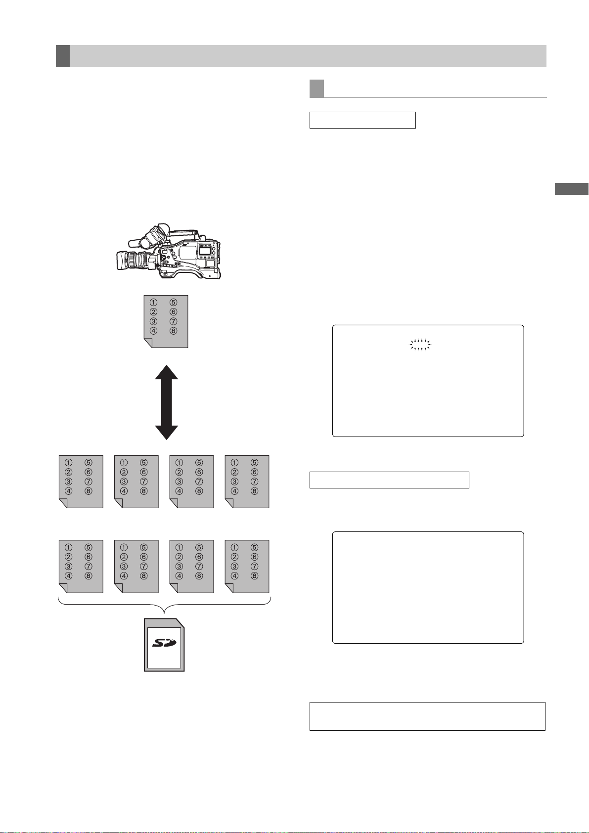
To write in and read out the lens file to/from the SD memory card
The contents of the eight lens files stored in the unit’s
internal memory can be saved onto an SD memory card
as card files under a single title. A total of eight titles can
be saved on an SD memory card.
Furthermore, the eight lens files saved under one title on
an SD memory card can be loaded into the unit
s internal
memory.
The correlation between the lens files stored in the internal
memory and lens files saved on an SD memory card is
shown below.
Internal memory
8 lens files
Card files
Up to 8 sets of the lens file
can be stored in the built-in
memory.
The contents of 8 lens files
can be saved onto an SD
memory card as card files
under one title or they can
be loaded from the SD
memory card.
Saving lens files on the SD memory card
Select the card file No.
1 Using menu operations, open the <LENS FILE CARD
R/W> screen from the FILE page.
When the message “FORMAT ERROR” appears in
the upper right corner, format the SD memory card
with the camera-recorder. SD cards can be formatted
through the CARD CONFIG menu option on the
READ/WRITE screen. For more information, see,
Handling SD memory cards] (page 84).
[
2 Turn the JOG dial button to move the arrow (cursor) to
the CARD FILE SELECT item.
3 Press the JOG dial button and the card file number
will flash. Turn the JOG dial button to select the file (1
to 8) to be recorded.
< LENS FILE CARD R/W >
#
CARD FILE S ELECT :1
READ
WRITE
TITLE READ
TITLE:
1: 5:
2: 6:
3: 7:
4: 8:
Adjustments and Settings for Recording
Title 1 Title 2 Title 3 Title 4
Title 5 Title 6 Title 7 Title 8
A total of 64 lens files (8 lens files
on an SD memory card.
k 8 titles) can be saved
4 Press the JOG dial button to enter the file number.
Give a title to the selected card file.
5 Turn the JOG dial button to move the arrow (cursor) to
the “TITLE :” item.
< LENS FILE CARD R/W >
CARD FILE S ELECT :1
READ
WRITE
TITLE READ
#
TITLE:
1: 5:
2: 6:
3: 7:
4: 8:
6 When the JOG dial button is pressed, the arrow
(cursor) moves to the title input area, and the input
mode is established.
Now perform step 7 on page 93 through step 15 on
page 94.
Adjustments and Settings for Recording : Handling data
95
Page 96

Loading lens files from the SD memory card
1 Using menu operations, open the <LENS FILE CARD
R/W> screen from the FILE page.
2 Turn the JOG dial button to move the arrow (cursor) to
the CARD FILE SELECT item.
3 Press the JOG dial button and the card file number
will flash. Turn the JOG dial button to select the file (1
to 8) to be read.
< LENS FILE CARD R/W >
#
CARD FILE S ELECT :1
READ
WRITE
TITLE READ
TITLE:
1: 5:
2: 6:
3: 7:
4: 8:
4 Press the JOG dial button to enter the file number.
Now perform steps 5 through 8 on page 94.
Note
The card file titles on the SD memory card are displayed
on the <LENS FILE CARD R/W> screen, but the titles of
the lens files contained in the card files are not shown on
this screen.
To display these titles, load the files, and check the titles on
the <LENS FILE> screen.
The lens files in the unit’s internal memory will be rewritten
as the loaded lens files at this time. For this reason, save
the lens files in the internal memory onto the SD memory
card first to back them up before loading them on the SD
memory card.
Adjustments and Settings for Recording : Handling data
96
Page 97

Preparation
Power Supply
A battery pack or an external DC power supply can be used as AJ-HPX2000’s power supply.
Using a Battery Pack
Battery packs from the following manufacturers can be
used:
• Anton/Bauer
• IDX
• PAC O
• Sony
The type of the battery can be checked or changed
through the viewfinder or menu screen on the monitor.
z Pressing the MODE CHECK button on the side of the
camera-recorder displays the current type of the battery
in the upper right corner of the viewfinder display.
z Navigate the menu to open the BATTERY/P2CARD
screen from the MAIN OPERATION page. Then, through
the BATTERY SELECT menu option, you can check and
change the battery type.
Preparation
#
< BATTERY/P2 CARD >
BATTERY SEL ECT :DIONIC90
EXT DC IN S ELECT :AC-ADPT
BATT NEAR E ND ALARM :OFF
BATT NEAR E ND CANCEL:ON
BATT END AL ARM :ON
BATT REMAIN FULL :70%
CARD NEAR E ND ALARM :ON
CARD NEAR E ND TIME :2min
CARD END AL ARM :ON
CARD REMAIN / :3m in/
Notes
z Other batteries may be used by changing the menu
setting, but system compatibility is not guaranteed.
z Charge the battery pack with the battery charger before
using it. (Please refer to the battery charger’s instruction
manual for information about charging.)
Preparation:Power Supply
97
Page 98

Mounting the Battery and Setting the Battery Type
Using an Anton/Bauer Battery Pack
1 Mount the Anton/Bauer battery pack.
Power supply output
connector for lighting
Anton/Bauer
Battery Pack
Lighting
control switch
<For your information>
The Anton/Bauer battery holder includes both a power
supply output connector for lighting and a lighting control
switch, which are convenient when attaching a light.
Please contact Anton/Bauer for information about the
lighting system.
3 Setting the battery type.
Select the battery type listed under BATTERY
SELECT. Select BATTERY SELECT from the
<BATTERY/P2CARD> screen in the MAIN
OPERATION page.
Please refer to [
more information.
The following Anton/Bauer batteries can be used:
• PROPAC14
• TRIMPAC14
• HYTRON50
• HYTRON100
• HYTRON140
• DIONIC90
• DIONIC160
BATTERY SETTING1] (page 179) for
2 Insert the battery and slide it in the direction of the
arrow.
Release lever
<For your information>
Removing the battery pack
Completely push down and hold the release lever on
the battery holder. Then, slide the battery pack in the
opposite direction to the arrow while holding the lever
down.
Preparation:Power Supply
98
Page 99

Using an NP-1 type battery pack
CAUTION:
These servicing instructions are for use by qualified
service personnel only. To reduce the risk of fire or
electric shock do not perform any servicing other than
that contained in the operating instructions unless you
are qualified to do so.
1 Remove the battery holder.
2 Mount the NP-1 type battery case on the camera-
recorder.
When using a V-mount type battery pack
Mount the V-mount adapter plate.
Insert the plate and slide it in the direction of the
arrow.
1 Tighten the mounting screws.
2 Tighten the power contact screws.
3 Insert the upper part of the removed cover in the
direction of the arrow.
4 Align the holes in the bottom part (metal part) of
the cover with the holes in the case, and secure the
cover with the screw.
Note
When mounting the battery holder, take care not to
pinch the connection cord.
Battery Case (for NP-1 type)
3 Setting the battery type.
Select the battery type listed under BATTERY
SELECT. Select BATTERY SELECT from the
<BATTERY/P2CARD> screen on the MAIN
OPERATION page.
When using another battery which cannot be selected
using the BATTERY SELECT item setting, select
TYPE A or TYPE B, and set the items that correspond
to the characteristics of the battery.
Please refer to [
more information.
BATTERY SETTING2] (page 180) for
Preparation
Note
For information about the V-mount adapter plate,
please contact the store where you purchased the
camera-recorder.
Preparation:Power Supply
99
Page 100

Use of the external DC power supply
1 Connect the external DC power supply to the DC IN
socket on the unit.
DC IN Socket
External DC
power supply
2 Turn “ON” the power switch of the external DC power
supply. (If the power switch is available on the external
DC power supply)
3 Turn ON the POWER switch on the unit.
Notes
z If both the battery pack and the external DC power
supply are connected, the electric power is supplied
from the external DC power supply. While the
external DC power supply is used, the battery can
be mounted and removed on/from the unit.
z
When the external DC power supply is used, ensure
that the power switch of the external DC power supply
is turned on first and then the POWER switch on the
unit is turned on. In the case of the reverse operation,
a malfunction may occur on the unit since the output
voltage of the external DC power supply is raised
slowly.
Inrush current is generated when the power of the unit
is turned on. Insufficient power supply when turning
on the power may cause a malfunction. We recommend using an external DC power supply with double
the capacity of the total power consumption of the unit
and any other connected device that is turned by interlocking with the power on of the unit (the viewfinder).
Select the DC cord that is recommended for the external DC power supply.
Confirm the pin arrangements of the DC output
connector of the external DC power supply and the
DC IN socket on the unit, and connect the proper
polarities to each other.
If the +12 V power supply is connected to the GND
connector in error, it may cause a fire or failure of
the unit.
Pin No. Signal
1
DC IN Socket
4
2
3
1GND
2, 3
4+12V
—
Preparation:Power Supply
100
 Loading...