

Page 1
■ This product is eligible for the P2HD 5 Year
Warranty Repair Program. For details,
see page 11.
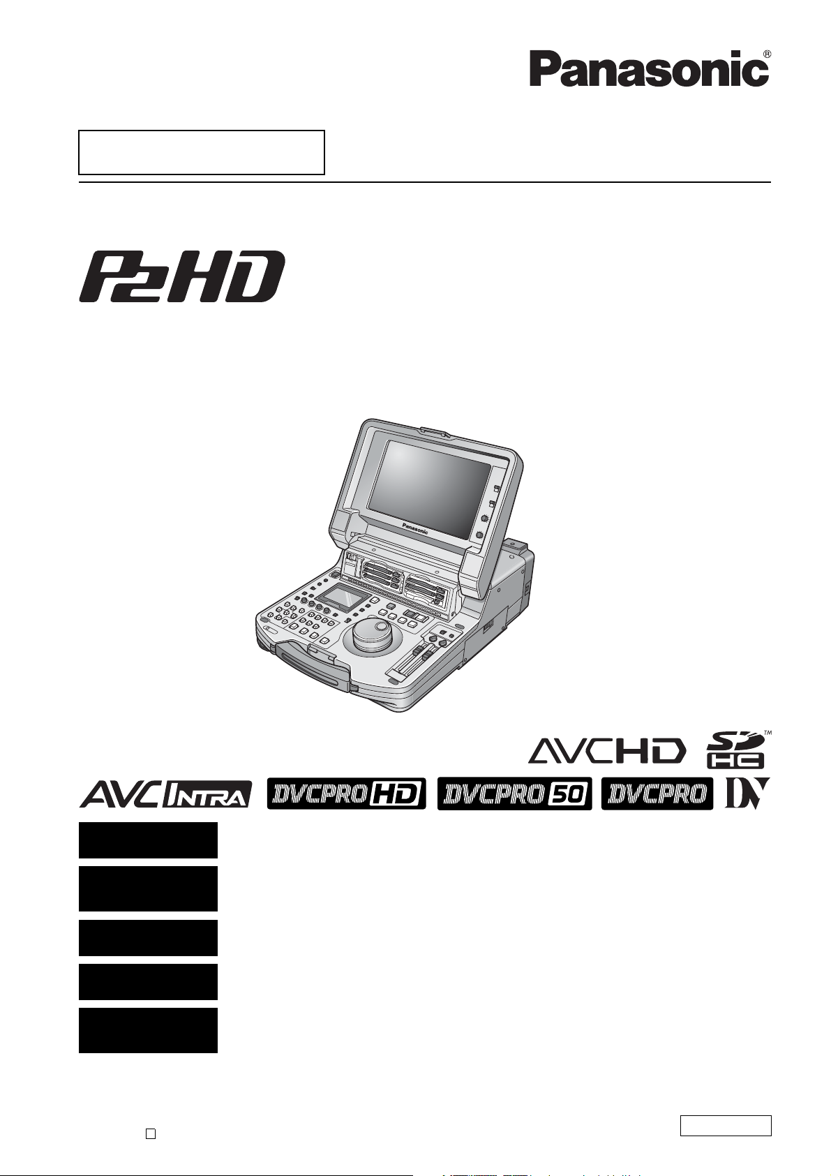
Memory Card Portable Recorder/Player
Operating Instructions
Model No. AJ-HPM200P
Model No. AJ-HPM200E
ENGLISH
Excerpted Version
DEUTSCH
Kurzversion
FRANÇAIS
Version extraite
ITALIANO
Estratto
ESPAÑOL
Versión extractada
Before operating this product, please read the instructions carefully and save this manual for future use.
• AVCHD capability is available when the optional AVCHD Codec board AJ-YCX250G is installed.
S0809T0 -P
Printed in Japan
D
This manual is an excerpted version of the full Operating Instructions. For more
information, please refer to the PDF manual provided on the supplied CD-ROM.
Dieses Handbuch stellt eine Kurzversion der vollständigen Bedienungsanleitung dar.
Weitere Informationen siehe PDF-Datei mit der Bedienungsanleitung auf der mitgelieferten
CD-ROM.
Ce manuel est une version extraite du mode d’emploi complet. Pour plus d’informations,
consultez le manuel au format PDF fourni sur le CD-ROM.
Questo manuale è un estratto dalle istruzioni per l’uso complete. Per ulteriori informazioni
fare riferimento al manuale in formato PDF fornito sul CD-ROM in dotazione.
Este manual es una versión extractada del manual de instrucciones completo. Para más
información, consulte el manual en formato PDF proporcionado con el CD-ROM
suministrado.
ENGLISH
VQT2G72
Page 2
Read this first! (For AJ-HPM200P)
CAUTION:
The mains plug of the power supply cord shall
remain readily operable.
The AC receptacle (mains socket outlet) shall be
installed near the equipment and shall be easily
accessible.
To completely disconnect this equipment from the
AC mains, disconnect the mains plug from the AC
receptacle.
CAUTION:
In order to maintain adequate ventilation, do not
install or place this unit in a bookcase, built-in
cabinet or any other confined space. To prevent
risk of electric shock or fire hazard due to
overheating, ensure that curtains and any other
materials do not obstruct the ventilation.
CAUTION:
To reduce the risk of fire or shock hazard and
WARNING:
This equipment must be grounded.
To ensure safe operation, the three-pin plug must
be inserted only into a standard three-pin power
outlet which is effectively grounded through normal
household wiring.
Extension cords used with the equipment must
have three cores and be correctly wired to provide
connection to the ground. Wrongly wired extension
cords are a major cause of fatalities.
The fact that the equipment operates satisfactorily
does not imply that the power outlet is grounded or
that the installation is completely safe. For your
safety, if you are in any doubt about the effective
grounding of the power outlet, please consult a
qualified electrician.
WARNING:
• To reduce the risk of fire or shock hazard, do not
expose this equipment to rain or moisture.
• To reduce the risk of fire or shock hazard, keep
this equipment away from all liquids. Use and
store only in locations which are not exposed to
the risk of dripping or splashing liquids, and do not
place any liquid containers on top of the
equipment.
annoying interference, use the recommended
accessories only.
CAUTION:
To reduce the risk of fire or shock hazard, refer
mounting of the optional interface boards to
qualified service personnel.
CAUTION:
This apparatus can be operated at a voltage in the
range of 100 – 240 V AC.
Voltages other than 120 V are not intended for
U.S.A. and Canada.
Operation at a voltage other than 120 V AC may
require the use of a different AC plug. Please
contact either a local or foreign Panasonic
authorized service center for assistance in selecting
an alternate AC plug.
CAUTION:
Excessive sound pressure from earphones and
headphones can cause hearing loss.
CAUTION:
A coin type battery is installed inside of the unit.
Do not store the unit in temperatures over 60 °C
(140 °F).
Do not leave the unit in an automobile exposed to
direct sunlight for a long period of time with doors
and windows closed.
The rating plate is on the underside of this equipment.
indicates safety information.
2
Page 3
Read this first! (For AJ-HPM200P) (continued)
IMPORTANT SAFETY INSTRUCTIONS
1) Read these instructions.
2) Keep these instructions.
3) Heed all warnings.
4) Follow all instructions.
5) Do not use this apparatus near water.
6) Clean only with dry cloth.
7) Do not block any ventilation openings. Install in accordance with the manufacturer’s instructions.
8) Do not install near any heat sources such as radiators, heat registers, stoves, or other apparatus (including amplifiers) that
produce heat.
9) Do not defeat the safety purpose of the polarized or grounding-type plug. A polarized plug has two blades with one wider
than the other. A grounding-type plug has two blades and a third grounding prong. The wide blade or the third prong are
provided for your safety. If the provided plug does not fit into your outlet, consult an electrician for replacement of the
obsolete outlet.
10)Protect the power cord from being walked on or pinched particularly at plugs, convenience receptacles, and the point where
they exit from the apparatus.
11)Only use attachments/accessories specified by the manufacturer.
12) Use only with the cart, stand, tripod, bracket, or table specified by the manufacturer, or sold with the apparatus.
When a cart is used, use caution when moving the cart/apparatus combination to avoid injury from tip-over.
13)Unplug this apparatus during lightning storms or when unused for long periods of time.
14)Refer all servicing to qualified service personnel. Servicing is required when the apparatus has been damaged
in any way, such as power-supply cord or plug is damaged, liquid has been spilled or objects have fallen into
the apparatus, the apparatus has been exposed to rain or moisture, does not operate normally, or has been dropped.
S3125A
Notice (U.S.A. only):
This product has a fluorescent lamp that contains mercury. Disposal may be regulated in your community
due to environmental considerations. For disposal or recycling information, please contact your local
authorities, or the Electronic Industries Alliance: http://www.eiae.org.
<For USA-California Only>
This product contains a CR Coin Cell Lithium Battery which contains Perchlorate Material - special
handling may apply.
See www.dtsc.ca/gov/hazardouswaste.perchlorate.
3
Page 4

Read this first! (For AJ-HPM200P) (continued)
FCC NOTICE (U.S.A.)
Declaration of Conformity
Model Number: AJ-HPM200P
Trade Name: Panasonic
Responsible Party: Panasonic Corporation of North America
One Panasonic Way, Secaucus, NJ07094
Support contact: Panasonic Broadcast & Television Systems Company
1-800-524-1448
This device complies with Part 15 of FCC Rules.
Operation is subject to the following two conditions:
(1)This device may not cause harmful interference, and (2) this device must accept any interference received, including
interference that may cause undesired operation.
To assure continued compliance, follow the attached installation instructions and do not make any unauthorized
modifications.
Note:
This equipment has been tested and found to comply with the limits for a class B digital device, pursuant to Part 15 of the
FCC Rules. These limits are designed to provide reasonable protection against harmful interference in a residential
installation. This equipment generates, uses, and can radiate radio frequency energy, and if not installed and used in
accordance with the instructions, may cause harmful interference to radio communications. However, there is no guarantee
that interference will not occur in a particular installation. If this equipment does cause harmful interference to radio or
television reception, which can be determined by turning the equipment off and on, the user is encouraged to try to correct
the interference by one of the following measures:
• Reorient or relocate the receiving antenna.
• Increase the separation between the equipment and receiver.
• Connect the equipment into an outlet on a circuit different from that to which the receiver is connected.
• Consult the dealer or an experienced radio/TV technician for help.
The user may find the booklet “Something About Interference” available from FCC local regional offices helpful.
Warning:
To assure continued FCC emission limit compliance, follow the attached installation instructions and the user must use only
shielded interface cables when connecting to host computer or peripheral devices. Also, any unauthorized changes or
modifications to this equipment could void the user’s authority to operate this device.
4
Page 5
Read this first! (For AJ-HPM200E)
WARNING:
This equipment must be earthed.
To ensure safe operation, the three-pin plug must
be inserted only into a standard three-pin power
point which is effectively earthed through normal
household wiring.
Extension cords used with the equipment must
have three cores and be correctly wired to provide
connection to the earth. Wrongly wired extension
cords are a major cause of fatalities.
The fact that the equipment operates satisfactorily
does not imply that the power point is earthed or
that the installation is completely safe. For your
safety, if you are in any doubt about the effective
earthing of the power point, please consult a
qualified electrician.
WARNING:
• To reduce the risk of fire or shock hazard, do not
expose this equipment to rain or moisture.
• To reduce the risk of fire or shock hazard, keep
this equipment away from all liquids. Use and
store only in locations which are not exposed to
the risk of dripping or splashing liquids, and do not
place any liquid containers on top of the
equipment.
CAUTION:
To reduce the risk of fire or shock hazard and
annoying interference, use the recommended
accessories only.
CAUTION:
To reduce the risk of fire or shock hazard, refer
mounting of the optional interface boards to
qualified service personnel.
CAUTION:
In order to maintain adequate ventilation, do not
install or place this unit in a bookcase, built-in
cabinet or any other confined space. To prevent
risk of electric shock or fire hazard due to
overheating, ensure that curtains and any other
materials do not obstruct the ventilation.
CAUTION:
The mains plug of the power supply cord shall
remain readily operable.
The AC receptacle (mains socket outlet) shall be
installed near the equipment and shall be easily
accessible.
To completely disconnect this equipment from the
AC mains, disconnect the mains plug from the AC
receptacle.
CAUTION:
Excessive sound pressure from earphones and
headphones can cause hearing loss.
CAUTION:
Do not remove panel covers by unscrewing them.
To reduce the risk of electric shock, do not remove
the covers. No user serviceable parts inside.
Refer servicing to qualified service personnel.
CAUTION:
A coin type battery is installed inside of the unit.
Do not store the unit in temperatures over 60 °C
(140 °F).
Do not leave the unit in an automobile exposed to
direct sunlight for a long period of time with doors
and windows closed.
The rating plate is on the underside of this equipment.
indicates safety information.
5
Page 6
Read this first! (For AJ-HPM200E) (continued)
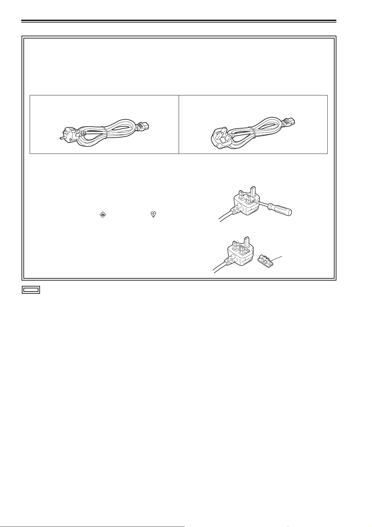
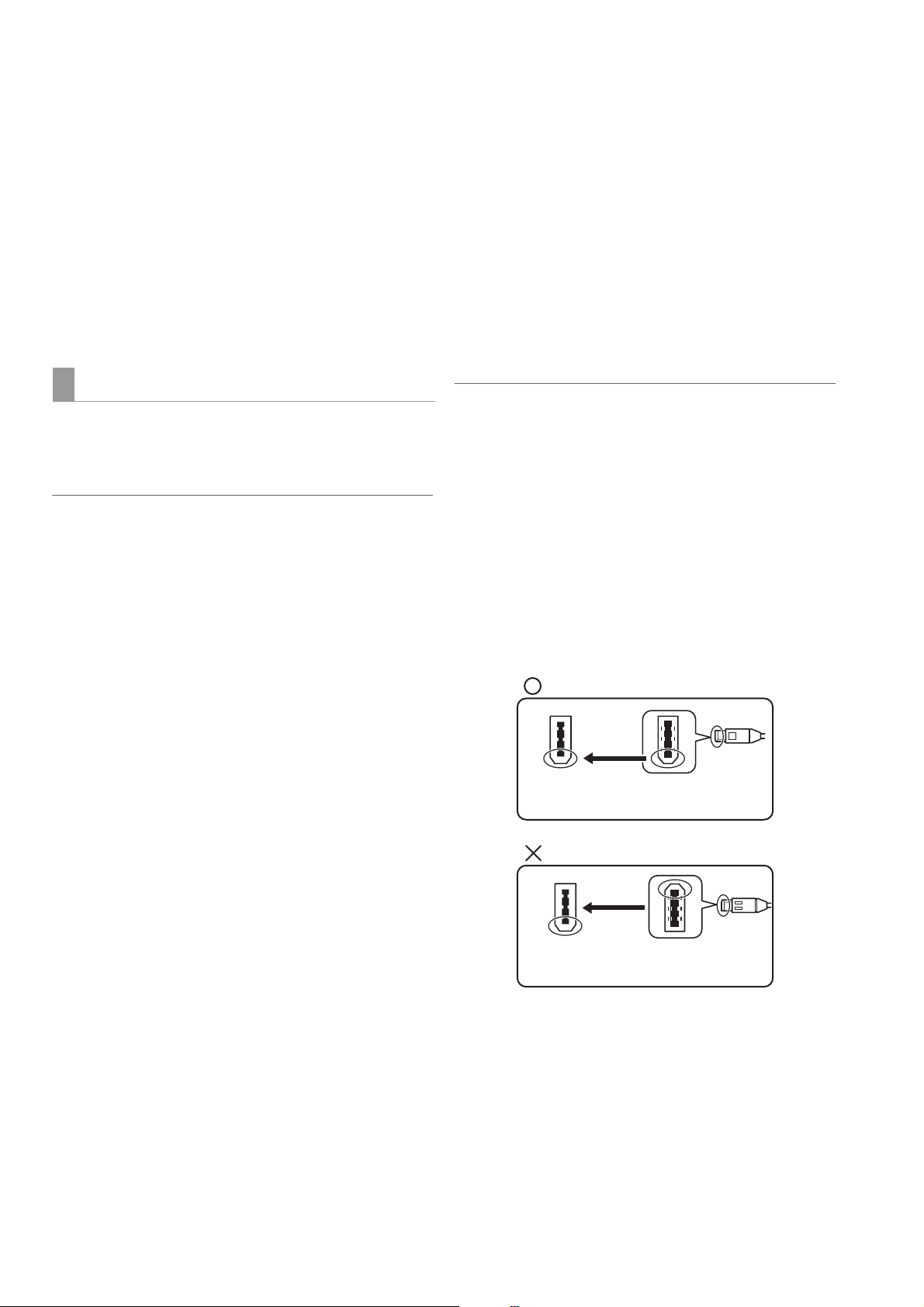
Caution for AC Mains Lead
FOR YOUR SAFETY PLEASE READ THE FOLLOWING TEXT CAREFULLY.
This product is equipped with 2 types of AC mains cable. One is for continental Europe, etc. and the other one is only for
U.K.
Appropriate mains cable must be used in each local area, since the other type of mains cable is not suitable.
FOR CONTINENTAL EUROPE, ETC.
Not to be used in the U.K.
FOR U.K. ONLY
This appliance is supplied with a moulded three pin
mains plug for your safety and convenience.
A 13 amp fuse is fitted in this plug.
Should the fuse need to be replaced please ensure that
the replacement fuse has a rating of 13 amps and that it
is approved by ASTA or BSI to BS1362.
Check for the ASTA mark or the BSI mark on the
body of the fuse.
If the plug contains a removable fuse cover you must
ensure that it is refitted when the fuse is replaced.
If you lose the fuse cover the plug must not be used until
a replacement cover is obtained.
A replacement fuse cover can be purchased from your
local Panasonic Dealer.
FOR U.K. ONLY
How to replace the fuse
1.Open the fuse compartment with a screwdriver.
2.Replace the fuse.
Fuse
indicates safety information.
EEE Yönetmeliğine Uygundur.
EEE Complies with Directive of Turkey.
indicates safety information.
6
Page 7

Read this first! (For AJ-HPM200E) (continued)
EMC NOTICE FOR THE PURCHASER/USER OF THE APPARATUS
1. Applicable standards and operating environment (AJ-HPM200E)
The apparatus is compliant with:
• standards EN55103-1 and EN55103-2 1996.11, and
• electromagnetic environments E1, E2, E3 and E4
2. Pre-requisite conditions to achieving compliance with the above standards
<1> Peripheral equipment to be connected to the apparatus and special connecting cables
• The purchaser/user is urged to use only equipment which has been recommended by us as
peripheral equipment to be connected to the apparatus.
• The purchaser/user is urged to use only the connecting cables described below.
<2> For the connecting cables, use shielded cables which suit the intended purpose of the
apparatus.
• Video signal connecting cables
Use double shielded coaxial cables, which are designed for 75-ohm type high-frequency applications,
for SDI (Serial Digital Interface).
Coaxial cables, which are designed for 75-ohm type high-frequency applications, are recommended
for analog video signals.
• Audio signal connecting cables
If your apparatus supports AES/EBU serial digital audio signals, use cables designed for AES/EBU.
Use shielded cables, which provide quality performance for high-frequency transmission applications,
for analog audio signals.
• Other connecting cables (IEEE1394, USB)
Use shielded cables, which provide quality performance for high-frequency applications, as
connecting cables.
• When connecting to the DVI signal terminal, use a cable with a ferrite core.
• If your apparatus is supplied with ferrite core(s), they must be attached on cable(s) following
instructions in this manual.
3. Performance level
The performance level of the apparatus is equivalent to or better than the performance level required by
these standards.
However, the apparatus may be adversely affected by interference if it is being used in an EMC environment,
such as an area where strong electromagnetic fields are generated (by the presence of signal transmission
towers, cellular phones, etc.). In order to minimize the adverse effects of the interference on the apparatus in
cases like this, it is recommended that the following steps be taken with the apparatus being affected and
with its operating environment:
1. Place the apparatus at a distance from the source of the interference.
2. Change the direction of the apparatus.
3. Change the connection method used for the apparatus.
4. Connect the apparatus to another power outlet where the power is not shared by any other
appliances.
To remove the battery
Back-up Battery (Lithium Battery)
• For the removal of the battery for disposal at the end of its service life, please consult your dealer.
7
Page 8

• SDHC logo is a trademark.
• miniSD logo is a trademark.
• “AVCHD” and “AVCHD” logo are trademarks of Panasonic Corporation and Sony Corporation.
®
•Microsoft
States and/or other countries.
• Microsoft product screen shots reprinted with permission from Microsoft Corporation.
• Names of products, brands, etc., appearing in this manual are trademarks or registered trademarks of their respective own-
ers.
• This product is licensed under the AVC Patent Portfolio License for the personal and non-commercial use of the following
activities of a consumer but no license is granted or implied for any other use.
- Encoding video in compliance with the AVC standard (hereafter referred to as “AVC video”).
- Decoding AVC video that was encoded by a consumer engaged in a personal and non-commercial activity.
- Decoding AVC video that was obtained from a video provider licensed to provide AVC video.
Additional information may be obtained from MPEG LA, LLC (http://www.mpegla.com).
- Using this product to make recordings on SD memory cards for distribution to end users for a commercial purpose requires
a separate license agreement from MPEG-LA. End user refers to a person or organization using content for private purpos-
es.
, Windows® and Windows Vista® are registered trademarks or trademarks of Microsoft Corporation of the United
Illustrations in this manual
• Note that illustrations of the unit and menu screens may differ from the ones you actually see.
Page references
• In this manual, references to pages are indicated as: (➝ page 00, PDF page 00).
Terminology
• The term “SD memory card” will be used below as a generic for SD and SDHC memory cards.
• A memory card with the “P2” logo (for example the separately sold AJ-P2C064AG) is referred to as a “P2 card.”
• A hard disk drive (HDD) is referred to as a “hard disk.”
• A continuous video recording created during a single recording is referred to as a “clip.”
• The state when the THUMBNAIL and PLAYLIST buttons are off is referred to as the “recording/playback mode.” (Refer to
page 30.)
8
Page 9

Contents
Read this first! (For AJ-HPM200P) ..............................................................2
Read this first! (For AJ-HPM200E) ..............................................................5
Accessories ...............................................................................................11
Included Accessories ................................................................................. 11
Optional Accessories .................................................................................. 11
Opening and Closing the Top Panel ..........................................................12
Introduction Features .....................................................................................................13
Control Reference Guide ...........................................................................16
Audio and Video Controller ......................................................................... 16
GUI Operations ........................................................................................... 20
Panel Control Unit and Card Slots .............................................................. 24
LCD Panel ................................................................................................... 25
Rear Panel ................................................................................................... 26
Side Panel ................................................................................................... 29
Moving Between Screens and Menu Operations .......................................30
Operating Modes ........................................................................................30
Menu Operations ......................................................................................... 31
Recording, Playback and P2 Card Handling ..............................................32
Insert a P2 Card .......................................................................................... 32
Recording and Playback .............................................................................32
Removing P2 Cards .................................................................................... 34
Preventing Accidental Deletion ................................................................... 34
Connections ...............................................................................................35
Example of Connections in 23.98/24/29.97/25 Hz Mode ............................ 35
Example of Connections for Remote Control .............................................. 35
Jog and Shuttle Operations Using the Search Dial ....................................36
Jog Mode .................................................................................................... 36
Shuttle Mode (SHTL Mode) .........................................................................36
Clip Management Thumbnail and Clip Management ..............................................................38
Thumbnail Screen Names and Functions ................................................... 39
Thumbnail Menu .......................................................................................... 42
Setup Unit Setup ..................................................................................................43
Changing Settings .....................................................................................44
Change Operations ..................................................................................... 44
Using a Lock to Protect the User Setting File ............................................. 45
Returning to Factory Defaults (Initial Settings) ............................................ 45
Setup Menu ................................................................................................. 46
Error Messages .......................................................................................................................................................48
WARNING Information Display ....................................................................................................................................... 49
Specifications ..........................................................................................................................................................58
9
Page 10

■ Information on software for this product
1. Included with this product is software licensed under the GNU General Public License (GPL) and GNU Lesser General Pub-
lic License (LGPL), and users are hereby informed that they have the right to obtain, change and redistribute the source
codes of this software.
Details on GPL and LGPL can be found on the installation CD provided with the unit. Refer to the folder called “LDOC”.
(Details are given in the original (English-language) text.)
To obtain the source codes, go to the following home page:
https://eww.pavc.panasonic.co.jp/pro-av/
The manufacturer asks users to refrain from directing inquiries concerning the source codes they have obtained and other
details to its representatives.
2. Included with this product is software which is licensed under MIT-License.
Details on MIT-License can be found on the installation CD provided with the unit. Refer to the folder called “LDOC”.
(Details are given in the original (English-language) text.)
3. This product contains software licensed under the OpenSSL License and SSLeay License. Details on OpenSSL and SSLeay
can be found on the installation CD provided with the unit. Refer to the folder called "LDOC". (Details are given in the original
(English language) text.)
■ Panasonic makes no guarantees for your recordings
Please understand that Panasonic makes no guarantees for your recordings in cases where video and/or audio were not
recorded as you intended due to problems with this unit, P2 cards, or SD memory cards.
■ What to remember when throwing memory cards away or transferring them to others
Formatting memory cards or deleting data using the functions of the unit or a computer will merely change the file management
information: it will not completely erase the data on the cards. When throwing these cards away or transferring them to others,
either physically destroy them or use a data deletion program for computers (commercially available) to completely erase the
data. Users are responsible for managing the data on their memory cards.
■ Place of Installation
Do not install this unit in a location exposed to direct sunlight as this may deform the cabinet or damage the LCD screen.
■ Liquid crystal displays
• While 99.99% or more of the pixels on an LCD screen will function normally, 0.01% may either be dead or constantly lit (seen
as red, blue or green dots). This is not a malfunction.
• There may be some unevenness on the screen depending on the image displayed.
• Wiping or rubbing the LCD screen with a rough cloth may damage it.
• Leaving an unchanging image on the screen for a long period of time may create a temporary afterimage (burn-in).
• LCD response and brightness vary with ambient temperature.
• In a high-temperature and high-humidity location, the LCD panel characteristics may change and result in uneven image quality.
10
Page 11
Accessories
Included Accessories
Power cable...................................................1 (AJ-HPM200P)
2 (AJ-HPM200E)
CD-ROM ................................................................................ 1
◆ NOTE:
• Be sure to appropriately dispose of the packing material when you have unpacked the product.
• Consult your supplier regarding purchase of accessories.
Optional Accessories
• AVCHD Codec board
AJ-YCX250G
◆ NOTE:
• Do not use optional boards other than the above product.
• Have your supplier install optional boards.
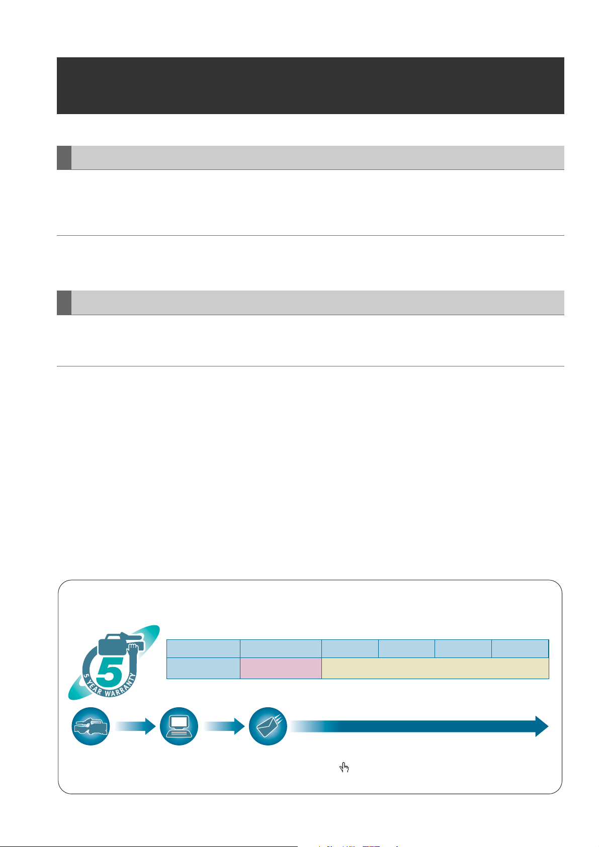
P2HD 5 Year Warranty Repair Program*
Thank you for purchasing this Panasonic P2HD device.
Register as a user for this device to receive a special service warranty up to five years of free warranty repairs.
Customers who register as users on the website will receive an extended warranty repair valid for up to
five years.
1st year 2nd year 3rd year 4th year 5th year
P2HD device
*1: Please note that this extended warranty is not available in some countries/regions. *2: Not all models eligible for extended warranty coverage.
*3: The basic warranty period may vary depending on the country/region. *4: Not all repair work is covered by this extended warranty.
*5: The maximum warranty period may be adjusted depending on the number of hours the device has been used.
2
*
Basic warranty
3
*
Extended warranty repair
1
5
*
4
*
Free 5 years of Warranty Repairs
Make sure to save the “Registration Notice” e-mail
Purchase
P2 product
Register online
within 1 month
“Registration Notice”
e-mail sent
Details about user registration and the extended warranty:
Please note, this is a site that is not maintained by Panasonic Canada Inc. The Panasonic Canada Inc. privacy policy does not apply and is not applicable in relation to any
information submitted. This link is provided to you for convenience.
during the warranty period.
http://panasonic.biz/sav/pass_e
Accessories
11
Page 12
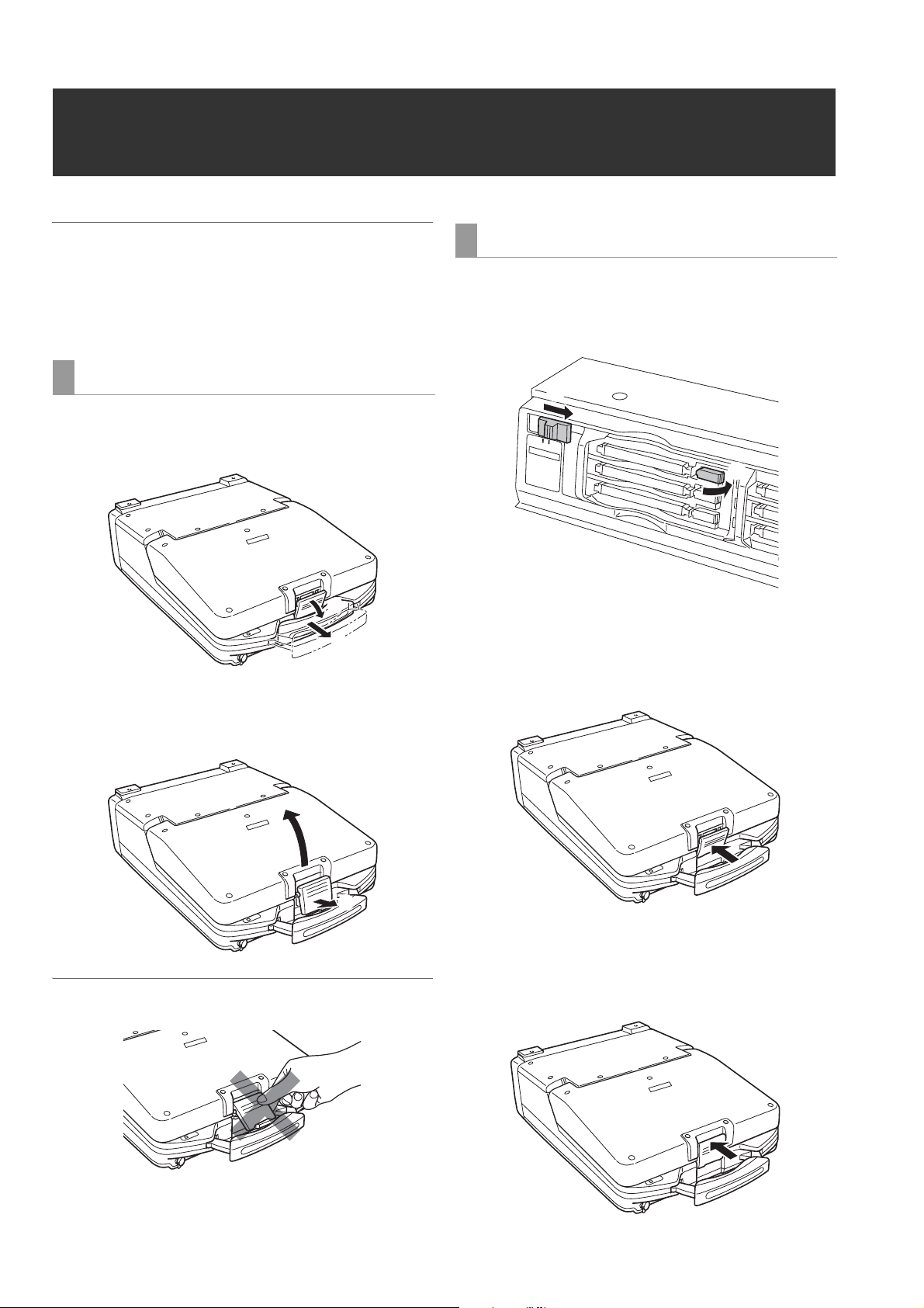
Opening and Closing the Top Panel
◆ NOTE:
• Take care to avoid pinching your fingers when opening and closing
the top panel.
• Check that the card lock is set to on before closing the top panel.
Never use force to close it when the lock is not set to on as this will
damage the unit.
Opening the top panel
1 Pull out the handle, then pull the top of the lever to-
wards you to release the lock.
②
①
2 Free the bottom of the lever. Then hold the top panel
and raise it to open.
Closing the top panel
1 Make sure the EJECT button is folded downwards.
If not folded, fold the EJECT button to the right and set the
card lock to on.
②
OFF
ON
C
A
R
D
L
OC
K
①
2 Close the top panel and engage the bottom of the le-
ver with the receptacle in the lower portion of the pan-
el assembly.
◆NOTE:
• Do not expose the lever to excessive force.
Opening and Closing the Top Panel
12
②
①
3 While making sure that the bottom of the lever has
been properly seated, press the top of the lever to-
wards the rear to lock it.
Page 13
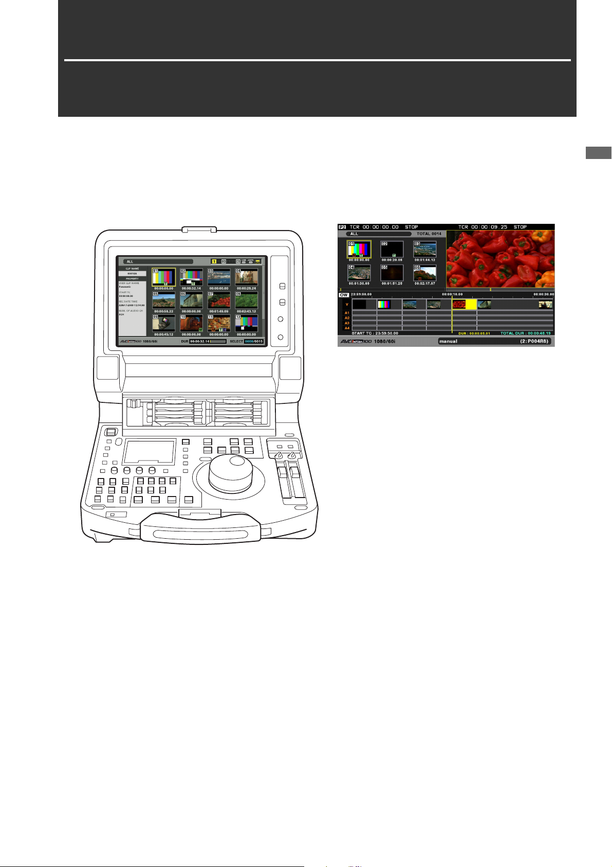
Introduction
Features
The AJ-HPM200 is a portable memory card recorder/player equipped with six P2 card slots and a 9-inch color LCD monitor.
It allows you to record and play back audio and video in the compressed DVCPRO HD, DVCPRO50, DVCPRO, DV and
AVC-Intra formats on the six P2 cards, to edit P2 card and hard disk video data and edit using an external VTR as a player.
The AJ-HPM200 comes with the following features.
Introduction
Introduction: Features
13
Page 14
■ Connecting a P2 Card Camera
A P2 card recorded in a P2 camera recorder plugs directly
into a PC card slot in this unit for immediate access. The P2
card is a semiconductor memory card that Panasonic
developed for professional AV use.
■ AVC-Intra standard feature
The AVC-Intra codec is provided as a standard feature.
An Intra-Frame compression format based on the H.264 video
compression standard makes possible a high compression
rate and high-quality image.
The AVC-Intra codec for this product is compatible with the
following two formats.
AVC-Intra 100: High-quality video supporting full-bit HD
AVC-Intra 50: Low-rate and low-cost operation
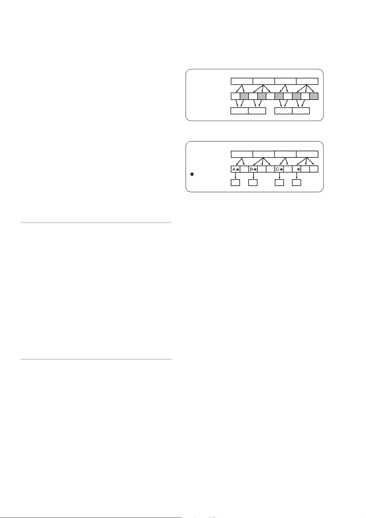
During native recording at a 59.94 Hz or 50 Hz setting in setup
menu No. 25 (SYSTEM FREQ), the unit produces pull-down
output.
Example of 1080-24PN (Native)
Camera video
2:3 pull-down
Native recording
Example of 720-24PN (Native)
Camera video
Ao Ae Bo Be Bo Ce Co De Do De
A C
BA C D
BA
B
DC
D
■ Built-in up/down/cross converter for output and
up converter for input
The AJ-HPM200 provides a built-in up/down/cross converter
for output as standard. It also up-converts composite and
SD-SDI input signals to record in the same HD format as the
system.
◆ NOTE:
• The cross converter function is not available during up-conversion
recording.
• SD closed caption signals during up-conversion recording are
recorded in the 608 HD (VANC) signal format (59.94 Hz only).
• Closed caption signals are not output during playback or down- and
cross-conversion.
• Nor are closed caption signals output during playback of up-
converted SD signals.
■ Frame rate conversion
Recording input from variable frame-rate cameras at 24PN
(Native), the unit is also capable of playing back cards
recorded at 24 fps and converting the output to 1080/24 PsF.
It can also record input from a variable frame-rate camera at
25PN (Native).
◆ NOTE:
• Do not use cards that have been edited or contain clips shot in
different formats as the loss of management data may prevent
normal playback.
■ Native recording
The unit provides support for native recording, a mode that
records only active frames. This provides longer recording
time when a VariCam, AJ-HPX2000/2100 or AJ-HPX3000 is
connected to the HD-SDI IN connector. Variable frame rate
(VFR) recording becomes possible by connecting a VariCam.
● Native recording defined
Native recording extracts only the active frames during 1080i
AVC-Intra recording as well as 720P DVCPRO HD and
AVC-Intra recording. At 720P, this lengthens the recording
time 2 to 2.5 times over pull-down recording.
2:3 pull-down
Active frames
Native recording
BB
A
BA
CD
C
D
D
D
■ Thumbnails for managing clips visually
The 9-inch color LCD monitor displays video clips
(thumbnails) stored on a P2 card. The viewer can select the
thumbnails he wants to see and change the order in which
they appear.
Clips can be selected from the thumbnail list for immediate
playback. The list also provides quick access to other clip
management operations such as copying and deleting,
adding shot marks and text memos as well as confirming and
editing clip data.
■ Expanded high-speed hard disk interface
● High-speed eSATA interface
The unit now supports hard disks using the eSATA interface,
which is faster than the regular USB interface. This interface
provides faster backup of video data on a P2 card to hard disk
and can restore hard disk data to a P2 card.
● Playback (best effort) and playlist editing of hard disk video
data
Video data on a hard disk can be viewed as thumbnails or a
*1
smooth
video stream. A protective feature ensures a
continuous audio output even if reading performance drops
due to use of a slow hard disk or through interference such as
vibrations.
*1
Playback of hard disk video data
enables editing of video
on a hard disk in the same way as editing video on a P2 card.
*1
Playback
*1: This does not guarantee playback without frame skipping.
of hard disk video data enables direct editing.
Introduction: Features
14
Page 15

■ Gigabit Ethernet network supported
● FTP client
In the thumbnail screen, this network allows to select video
stored on a P2 card or external hard disk and transfer it at high
speed via an FTP server on the Internet. Video stored on an
FTP server can be displayed and selected as a thumbnail for
downloading to a P2 card or external hard disk. And SD
memory card data can be sent by the card to and from an FTP
server. The network also enables transmission of data
encrypted using SSH.
● Browser
A browser mode enables the user to browse web sites with
web page authentication required for connecting to the
Internet.
● FTP server
The unit can operate as an FTP server allowing a computer or
other FTP client to load video files stored on P2 cards or in an
external hard disk.
● SAMBA server
When connected to a Windows computer or other network
computer, the unit can operate as a SAMBA server to load
video files stored on P2 cards or in an external hard disk.
● HTTP server
Using the unit as an HTTP server allows you to view lists of
video data from a browser on a computer, view metadata, and
play back proxy data.
■ Audio AES/EBU input and output supported
(16 bit, 48 kbps/4 ch)
The unit comes with a 4-channel AES/EBU input and output
interface as standard. This enables interfacing with digital
audio equipment and digital VTRs using a 48 kHz sampling
rate.
■ AVCHD option (AJ-YCX250G)
Installation of the AJ-YCX250G, an optional AVCHD codec
board, will enable recording and playback of the AVCHD
format on SD memory cards.
This makes the following possible.
• Dubbing AVCCAM recorded clips onto a P2 card in the
DVCPROHD or AVC-Intra format, playlist editing of such
clips and ingesting such clips to non-linear editor.
• Dubbing P2 card clips recorded on a P2HD camera-
recorder to an SD memory card in the AVCHD format.
• HD-SDI or other external input can be recorded as
DVCPROHD or AVC-Intra to a P2 card simultaneous with
recording of the same input in AVCHD format video on an
SD memory card.
■ Waveform and vector display
The LCD screen can display either video waveform or vector
waveform.
During up-conversion, a waveform is displayed after up-
conversion.
Introduction
■ Editing and GUI
● Independent audio and video editing
Any video and audio (4ch) tracks can be independently
selected for editing.
● Insert editing and overwrite editing
Two types of editing are available: insert editing, in which new
events are added between two editing events and overwrite
editing, in which a new event overwrites an event.
● Two screens for editing material and playlist video
Editing material (player) and playlist (recorder) video appear
in two screens at all times. A timeline indicating editing status
appears simultaneous with these screens for intuitive editing.
● Capability to edit both tape and hard disk material
Use of a VTR or similar device with an RS-422A interface as
player makes possible linear-like editing (deck-to-deck
editing). Video data transferred to an eSATA or USB hard disk
can also be edited.
● Function for adjusting audio level (variable) of any section
Preview and audio level adjustments make it possible to
operate the audio playback fader for the required audio
section to adjust the audio level (variable).
● Display and playback of player thumbnails
A player using P2 cards or a hard disk can display player
thumbnails. Thumbnails can be set to limit the clips used by
the player to the required clips.
◆ NOTE:
• A waveform is not displayed when there is no input signal.
■ HD-SDI remote
When the unit is connected to a camera-recorder with an
external device control, start and stop of recording of HD-SDI
signal input can be automatically controlled through
recording start and stop signals in the input.
■ USB keyboard
A USB keyboard can be connected to enable the following
functions.
● Entry and editing of clip metadata
● Network setup, browser
◆ NOTE:
• Some USB keyboards may not enable normal input.
■ VANC data recording/playback function
(59.94 Hz, 50 Hz only)
Recording and playback of ancillary data (VANC data) of up
to 5760 bytes per frame conforming to SMPTE 291M is
superimposed on the vertical blanking area of video.
Introduction: Features
15
Page 16
Control Reference Guide
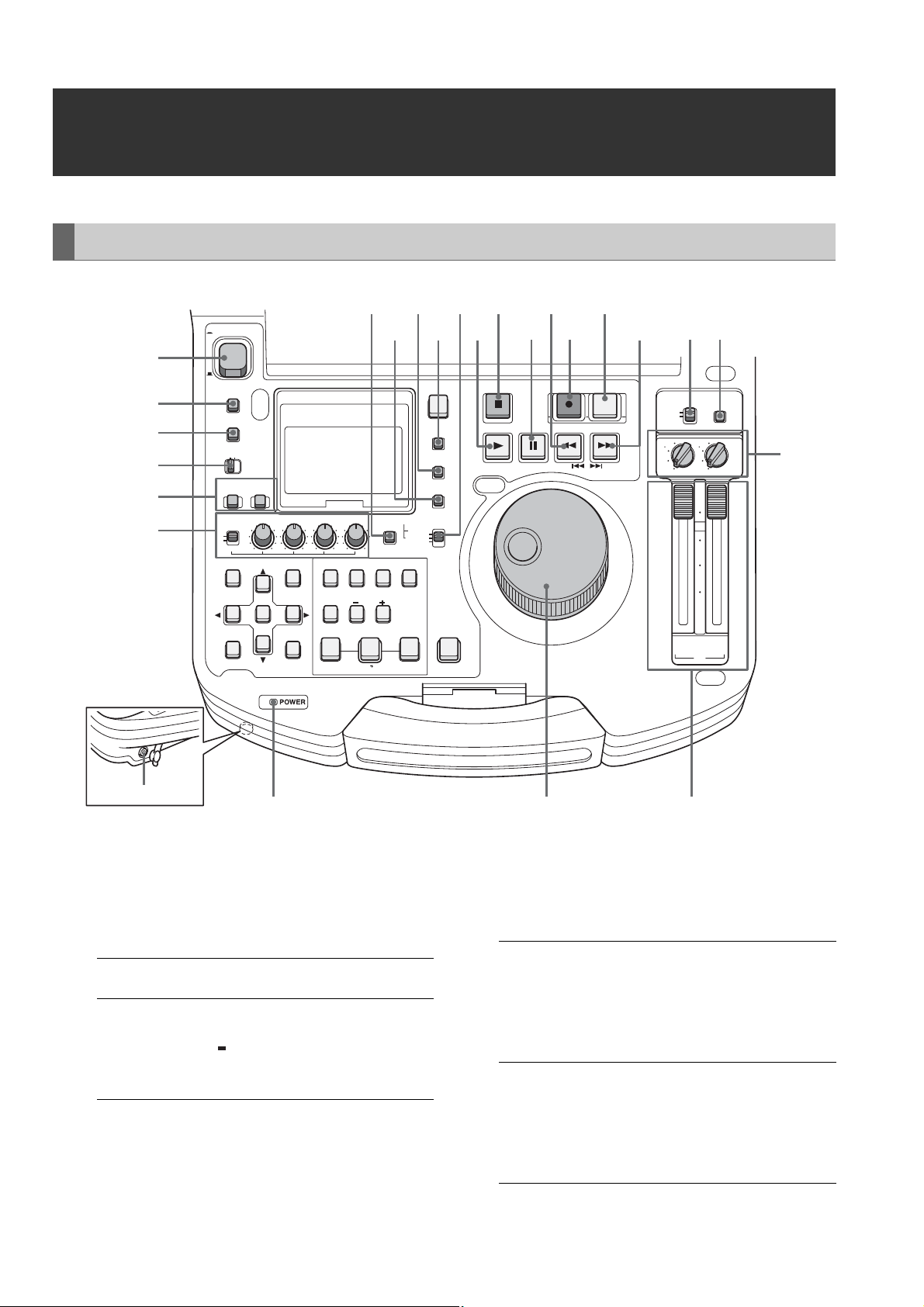
Audio and Video Controller
ON
POWER
18
202224
19
2123 15
17
16
14
1213 11
1
OFF
METER
2
3
FULL/FINE
MONITOR
SELECT
METER SELECT
CH 1-4 CH 5-8
4
INPUT SELECT
5
6
VIDEO AUDIO
CH 1 CH 2 CH 3 CH 4
REC
VAR
UNITY
THUMBNAIL
SET
MULTI
SEL
EXIT
CANCEL/PF
PLAYLIST
MENU
DIAG
OPERATION
EDIT MODE
LAST X
DELETE
SLOT CLIP
MARKER
VIDEO GO TO
A1A3A2
TRIM
SLOT SELECT
ENTRY
IN
CLIP LIST
PF1
PF2
TEXT
MEMO
A4
INT
REGEN
PRESET
A.DUB
MODE
OUT
ALL CLIP
PF3
PLAYER
SOURCE SELECT
COUNTER
RESET
NEW
TC PRESET
PROP
TCG
EXT
SHIFT
STOP
STILL/
PAUSE
PLAY
REVIEW
1 CLIP PLAY
PF4
PREV
REC
REW
PREVIEW
A.LEVEL REC
FF
NEXT
CONTROL
REMOTE
LOCAL
3
1 3
1
UNITY
MODE
4
2 4
2
UNITY
10
0
10
20
30
CH
CH
2/4
1/3
PB
10
Headphones jack
1. POWER switch
Turns the power on and off.
2. METER (FULL/FINE) selector button
Switches the scale of the audio level meter.
FULL mode: Selects the standard scale
(– ∞ to 0 dB range)
FINE mode: Selects a scale divided into 0.5 dB
increments.
“ ” indicates reference level (as
set in setup menu) on a scale
divided into 0.5 dB increments.
987
3. AUDIO MONITOR SELECT button
Switches the audio signals to be output to the MONITOR L/R
connectors and the headphones jack. Each press of the
button switches the output signals to the MONITOR L/R
connectors and the headphones jack as described below.
When the METER
SELECT switch is set to
CH 1 to 4:
When the METER
SELECT switch is set to
CH 5 to 8:
(selectable only with HD
format)
The L/R lamps in the audio level meter indicate which
signal is selected.
[CH1 / 2]➝[CH3 / 4]➝
[CH1 / 1]➝[CH2 / 2]➝
[CH3 / 3]➝[CH4 / 4]➝
[CH1+2 / 1+2]➝
[CH3+4 / 3+4]➝
[CH1+3 / 2+4]
[CH5 / 6]➝[CH7 / 8]➝
[CH5 / 5]➝[CH6 / 6]➝
[CH7 / 7]➝[CH8 / 8]➝
[CH5+6 / 5+6]➝
[CH7+8 / 7+8]➝
[CH5+7 / 6+8]
Introduction: Control Reference Guide
16
Page 17

4. METER SELECT switch
Switches to CH1-4 or CH5-8 in the audio meter and the
monitor.
5. INPUT SELECT buttons
Switch between video and audio input signals.
VIDEO: Press the VIDEO button to open a screen
for selecting input signal. Pressing the
button when the screen is open enables
selection of CMPST, HDSDI, SDSDI, 1394
or SG input. When SG is selected, the
signal switches to the internal signal
selected in setup menu No. 601 (VIDEO
INT SG).
Selecting composite or SD SDI when
setup menu No. 020 (SYS FORMAT) is set
to 1080i or 720p automatically up-converts
SD to HD when recording. The unit
indicates this as CMPST (U/C) and SDSDI
(U/C).
AUDIO: Press the AUDIO button to open a screen
for selecting input signal. Pressing the
button when the screen is open enables
selection of ANALOG, AES/EBU, SDI or
SG input.
◆ NOTE:
• When VIDEO is set to 1394, AUDIO is automatically set to
1394.
• The selected input item blinks when there is no input signal.
• Press the INPUT SELECT button once to show the current
setting. When you do not want to change the setting, press
the EXIT button or wait for 3 seconds to allow the display of
the current setting to vanish.
6. AUDIO REC VOL SEL switch
UNITY/VAR switch
UNITY: Records the audio signals at a fixed level
regardless of the positions of the audio
level controls.
VAR: Records audio signals at the level set with
the audio level controls.
Audio level controls
Use these controls to adjust the recording levels of the
audio signals (CH1/CH2/CH3/CH4). However, the
recording level cannot be adjusted during 1394 input.
8. Search dial
Use to search and check video.
➝Refer to “Jog and Shuttle Operations Using the
Search Dial” (page 36).
Hold down the SHIFT button and turn the search dial to
perform high-speed scrolling in the thumbnail screen.
➝Refer to “Thumbnail and Clip Management” (page
38).
9. Audio playback level controls
Adjust the playback level of audio signals (of channels
selected using the UNITY/VAR channel select switch).
However, they cannot adjust the playback level of
1394 output signals. CH5 to 8 are at all times played
back at a fixed level.
10.UNITY/VAR channel select switches
UNITY: Plays back audio signals at a fixed level
regardless of the positions of the audio
level controls.
1(2): Plays back and outputs audio CH1(2) at
the level adjusted using the audio level
controls to CH1(2) and at a fixed level to
CH3(4).
1+3
(2+4):
3(4): Plays back and outputs audio CH3(4) at
Plays back and outputs audio CH1(2) and
CH3(4) at the level adjusted using the
audio level controls to CH1(2) and CH3(4).
the level adjusted using the audio level
controls to CH3(4) and at a fixed level to
CH1(2).
11.MODE button
Switch to the USB device mode for connecting a
personal computer, to the network server mode,
browser mode or AVCHD mode (available only with
optional equipment).
Press this button to open the mode selection screen on
the LCD monitor and select the desired mode.
➝For details, refer to “Using USB or eSATA
Connectors” (PDF page 112).
➝Refer to “Connecting This Unit to a Network” (PDF
page 126).
➝Refer to “Operating the AVCHD Thumbnail Screens”
(PDF page 143).
Introduction
7. POWER indicator
Lights when the power is on.
Introduction: Control Reference Guide
17
Page 18

12.CONTROL switch
REMOTE:
LOCAL: Select this position to control the unit from
Select this position to control the unit
through AV/C commands via the 9-pin
REMOTE or IEEE1394.
the operation panel.
13.FF/NEXT buttons
FF button
Press to start fast forward playback. Select the speed
in setup menu No. 102 (FF. REW MAX).
NEXT (SHIFT + FF) button
Press this button during playback to move to the
beginning of the next clip or the beginning of a clip or
text memo. During playback of a recorder in playlist
mode, the beginning of the next video event is located.
The operation interrupted by this function is resumed
when clip beginning is located.
In the thumbnail display, press this button to move to
the last thumbnail.
14.PREVIEW/A LEVEL REC button
PREVIEW button
Press this button to preview (playback from the IN
point of set preroll time to 1 sec past the OUT point)
edit in playlist mode.
➝Refer to “Buttons Used in Playlist Operations” (PDF
page 82).
A LEVEL REC (SHIFT + PREVIEW) button
Adjust level of audio tracks.
➝Refer to “Buttons Used in Playlist Operations” (PDF
page 82).
15.REC button
Press this button and the PLAY button simultaneously
to start recording. During playback, press this button
to check EE mode video and audio on the monitor. (EE
mode is not available during IEEE1394 input) Press the
STOP button to return to the original video and audio.
In playlist mode, press this button to check edit results.
16.REW/PREV button
REW button
Press to rewind. Select the speed in setup menu No.
102 (FF. REW MAX).
PREV (SHIFT + REW) button
During playback, press this button to move to the
beginning of the current clip, the next clip or text
memo. During playback of a recorder in playlist mode,
the beginning of the previous video event is located.
The operation interrupted by this function resumes
when the beginning of a clip is located.
In the thumbnail display, press this button to move to
the first thumbnail.
17.STILL/PAUSE button
Press this button to engage the search mode and
display a still picture. In the search mode, you can use
the search dial for JOG and SHTL (shuttle) operations.
18.STOP button
Press this button to stop. When the setting in setup
menu No. 122 (STOP EE SEL) is PB, you can monitor
freeze pictures and when set to EE, you can monitor
input video.
19.PLAY/REVIEW/1 CLIP PLAY button
PLAY button
Press to start playback.
Press this button and the REC button simultaneously to
start recording.
1 CLIP PLAY (SHIFT + PLAY) button
In the thumbnail display, press this button to play back
the clip at the cursor location. During playback only the
STOP button is available.
REVIEW (SHIFT + PLAY) button
In playlist mode, press this button to review the event
at the cursor location.
➝Refer to “Buttons Used in Playlist Operations” (PDF
page 82).
Introduction: Control Reference Guide
18
Page 19

20.TCG switch
INT REGEN: The internal time code generator
synchronizes with the time code
read by the time code reader from
the P2 card. Select whether to make
TC or UB the REGEN in setup menu
No. 505 (TCG REGEN).
INT PRESET: Uses the internal time code
generator of this unit. Settings can
be preset on the operation panel
and the remote control panel.
➝Refer to “Time Code, User Bit and
CTL” (PDF page 185).
EXT: Uses the external time code input
from the TIME CODE IN connector
or video signal VITC, SLTC, SVITC
and IEEE1394 digital input
connectors. Select in setup menu
No. 507 (EXT TC SEL).
21.COUNTER button
Press to switch the counter display of the LCD panel.
Each press of this button changes the counter display
as follows: [CTL (relative position from the beginning)]
➝ [TC (read time code)] ➝ [UB (user bit of the read
time code)].
22.RESET/NEW button
RESET button
Press this button when the LCD panel counter is in the
CTL mode to reset the counter display to [0:00:00:00].
Hold down the TC PRESET button and press this
button when the LCD panel counter is in the TC mode
(read time code) or UB mode (user bit of the read time
code) to reset the time code generator.
When using the on-screen keyboard, use this button to
delete all text, IN/OUT points in playlists, etc.
NEW (SHIFT+RESET) button
Use these buttons in the playlist.
➝Refer to “Creating a New Playlist” (PDF page 87).
23.TC PRESET/PROP button
TC PRESET button
Use to set TC and UB values.
➝Refer to “Time Code, User Bit and CTL” (PDF page
185).
PROP (SHIFT + TC PRESET) button
In the thumbnail and playlist screen (when no menu is
displayed), press the SHIFT button and this button
simultaneously to show the property of a clip or an
event.
➝Refer to “Viewing and Revising Clip Information”
(PDF page 61).
24.TEXT MEMO/MARKER button
TEXT MEMO: Press this button during recording
and playback where you wish to
enter a text memo. In the thumbnail
screen, press this button to add a
text memo at the start of a clip.
➝For details, refer to “Attaching
Text Memos” (PDF page 56).
MARKER: In the thumbnail screen, while
pressing the SHIFT button, press
this button to turn shot mark display
of the clip at the pointer position on
and off.
➝For details, refer to “Attaching
Shot Marks” (PDF page 57).
Introduction
Introduction: Control Reference Guide
19
Page 20

GUI Operations
POWER
ON
18 16 15 14 13
17
OFF
METER
FULL/FINE
MONITOR
SELECT
METER SELECT
CH 1-4 CH 5-8
INPUT SELECT
VIDEO AUDIO
CH 1 CH 2 CH 3 CH 4
REC
VAR
UNITY
1
2
THUMBNAIL
3
EXIT
SET
MULTI
SEL
PLAYLIST
MENU
4
CANCEL/PF
DIAG
OPERATION
57
1. PLAY LIST button
Press to start or end playlist mode.
➝Refer to “Playlist Function” (PDF page 74).
PLAYER
SOURCE SELECT
COUNTER
RESET
NEW
TC PRESET
INT
REGEN
PRESET
A.DUB
MODE
OUT
ALL CLIP
PF3
EXT
PROP
TCG
SHIFT
PF4
TEXT
MEMO
MARKER
VIDEO GO TO
A1A3A2
EDIT MODE
LAST X
DELETE
IN
SLOT CLIP
PF1
6 9 10 11 12
TRIM
SLOT SELECT
ENTRY
CLIP LIST
8
A4
PF2
PREVIEW
A.LEVEL REC
STILL/
PAUSE
PREV
REC
REW
FF
NEXT
CONTROL
REMOTE
LOCAL
3
1 3
1
UNITY
MODE
4
2 4
2
UNITY
10
0
10
20
30
∞
CH
CH
2/4
1/3
PB
STOP
PLAY
REVIEW
1 CLIP PLAY
selects all track events with the same IN and OUT
points as the event at the cursor.
2. THUMBNAIL button
Press this button and the button lights, and the
thumbnail screen appears on the LCD monitor. Press
again to return to video playback and the button goes
out.
Setting setup menu No051 (GUI OUTPUT) allows you
to transfer the thumbnail screen and the playlist screen
to the video output.
3. Cursor buttons (b/a/4/5)
The four outer buttons are cursor buttons. Use them to
move the cursor in thumbnails, menus, events, etc. The
SET button at the center is used to select menu items
and clips.
In the thumbnail or playlist screen, hold down the
SHIFT button and press a cursor button to move the
cursor to the beginning or the end. Or hold down the
SHIFT button and press the SET button to select
multiple clips or events.
Holding down the SET button in the playlist screen,
4. EXIT/CANCEL/PF button
When the PLAYLIST/
THUMBNAIL buttons
are lit:
When the PLAYLIST/
THUMBNAIL buttons
are off:
Press this button to return
from clip property, card
status or HDD thumbnail to
the previous screen.
Selecting [EXIT] in a menu
has the same effect as
pressing the SET button.
Press the SHIFT button and
this button simultaneously
to cancel a selection.
Press this button to use the
7 (IN), 9 (ENTRY), 11 (OUT)
and 12 (SHIFT) buttons as
PF1 to PF4, respectively.
Press this button again
before pressing another
button and this mode will
close after a short interval.
➝Refer to “Making
changes using the PF
buttons” (page 44).
Introduction: Control Reference Guide
20
Page 21

5. MENU/DIAG/OPERATION button
MENU button
Press this button to open the setup menu, thumbnail or
playlist menus. Press again to return to the previous
screen.
➝Refer to “Moving Between Screens and Menu
Operations” (page 30).
Refer to “Setup” (page 43).
DIAG (SHIFT+MENU) button
When not in the thumbnail or playlist screen, press this
button to show information about this unit. Press again
to return to the previous screen. However, in the
thumbnail or playlist screen, it has the same effect as
pressing the OPERATION (SHIFT + MENU) button.
Information about this unit includes [VIDEO SYSTEM],
[WARNING], [HOURS METER], [UMID] and [DIF]. Use
the SET button or the right and left cursor buttons
(b/a) to switch among them.
[VIDEO SYSTEM]
screen:
[WARNING] screen: Shows warning
[HOURS METER]
screen:
[UMID] screen: Shows UMID information
[DIF] screen: Shows various information
OPERATION (SHIFT + MENU) button
In the thumbnail and playlist screen (when no menu is
displayed), press the SHIFT button and this button
simultaneously to show and select the [OPERATION]
menu.
Shows current system
frequency, recording
format, input and output
formats and other
information.
information.
Shows the unit serial
number, the number of
hours it has been on, and
the number of times it has
been switched on and off.
for the current video.
on the current DIF (the
IEEE 1394 interface).
7. IN/SLOT CLIP/PF1 button
IN button
Use this button to perform the following functions
during clip playback or when the unit is controlled
externally.
•IN+ENTRY
Press the ENTRY button and this button to set an IN
point.
•IN
Press this button to confirm a set IN point. “--:--:--:--”
is displayed when no point has been set.
• IN+RESET
Press the RESET button and this button
simultaneously to delete the current IN point.
•IN+GOTO
Press the GOTO button and this button
simultaneously to cue up to the set IN point.
SLOT CLIP (SHIFT + IN) button
In the thumbnail screen, each simultaneous press of
the SHIFT button and this button switches the clip
display between a specific SLOT or selected clip.
PF1 button
In recording/playback mode, press this button after
pressing the PF button to start the setup menu
operation registered in the PF1 button.
8. TRIM – /SLOT SELECT – button
SLOT SELECT – (SHIFT + TRIM –) button
Hold down the SHIFT button and this button
simultaneously to move to the previous recording slot
position. Pressing this button when the unit is in slot 1
results in a move to slot 6.
TRIM – button
Use this button to move to a hard disk partition.
➝Refer to “Displaying Clip Thumbnails on a Hard Disk”
(PDF page 121).
Use this function for trimming.
➝Refer to “Buttons Used in Playlist Operations” (PDF
page 82).
Introduction
6. LAST X/DELETE button
LAST X button
In the playlist mode, use this button to return a previous
editing operation.
➝Refer to “Buttons Used in Playlist Operations” (PDF
page 82).
DELETE (SHIFT + LAST X) button
In the thumbnail or playlist screen, press this button to
delete the selected clip or event.
Introduction: Control Reference Guide
21
Page 22

9. ENTRY/CLIP ➝ LIST/PF2 button
ENTRY button
During clip playback or control of an external device,
press the IN or OUT button simultaneous with this
button to set an IN or OUT point.
CLIP ➝ LIST (SHIFT + ENTRY) button
Clip load function
➝Refer to “Buttons Used in Playlist Operations” (PDF
page 82).
PF2 button
In recording/playback mode, press this button after
pressing the PF button to start the setup menu
operation registered in the PF2 button.
10.TRIM + /SLOT SELECT + button
SLOT SELECT + (SHIFT + TRIM+) button
Hold down the SHIFT button and this button
simultaneously to move to the previous recording slot
position. Pressing this button when the unit is in slot 6
results in a move to slot 1.
TRIM + button
Use this button to move to a hard disk partition.
➝Refer to “Displaying Clip Thumbnails on a Hard Disk”
(PDF page 121).
Use this function for trimming.
➝Refer to “Buttons Used in Playlist Operations” (PDF
page 82).
11.OUT/ALL CLIP/PF3 button
OUT button
Use this button to perform the following functions
during clip playback or when the unit is controlled
externally.
•OUT + ENTRY
Press the ENTRY button and this button to set an
OUT point.
•OUT
Press this button to confirm a set OUT point.
“--:--:--:--” is displayed when no point has been set.
• OUT + RESET
Press the RESET button and this button
simultaneously to delete the current OUT point.
•OUT + GOTO
Press the GOTO button and this button
simultaneously to cue up to the set OUT point.
ALL CLIP (SHIFT + OUT) button
In the thumbnail screen, press the SHIFT button and
this button simultaneously to return the clip display to
ALL.
PF3 button
In recording/playback mode, press this button after
pressing the PF button to start the setup menu
operation registered in the PF3 button.
12.SHIFT/PF4 button
SHIFT
Use this button together with the FF, REW and SET
buttons (short cut keys).
➝Refer to “List of Shortcuts” (PDF page 205).
PF4
In recording/playback mode, press this button after
pressing the PF button to start the setup menu
operation registered in the PF4 button.
13.PLAYER/ SOURCE SELECT button
PLAYER button
Use this button to control an external device or operate
a player in playlist mode.
• In modes other than thumbnail or playlist mode:
Switches to operation of an external device
(RS-422A). Pressing PLAY or other operation button
will remote control an external device and display
externally input video, audio and time code.
• In playlist mode:
Switches to player/recorder.
➝Refer to “Preparing for Playlist Creation” (PDF
page 86)., “Buttons Used in Playlist Operations”
(PDF page 82).
SOURCE SELECT (SHIFT + PLAYER) button
• In recording/playback mode:
Switches to operation of an IEEE1394 connected
device.
• In playlist mode:
Sets the source (interface) used as a player.
➝Refer to “Playlist Function” (PDF page 74).
14.GO TO/ A.DUB MODE button
GO TO button
Hold down this button and press the IN/OUT button to
cue up to an IN or OUT point.
◆ NOTE:
• Cue up may fail when the time code is not continuous. Be
sure to use a continuous time code.
A. DUB MODE (SHIFT + GOTO) button
Press this button to engage the A. DUB mode and
record voice-overs.
➝Refer to “Recording Voice-Overs” (PDF page 102).
Introduction: Control Reference Guide
22
Page 23

15.A2/A4 button
Use to select material for editing in the playlist mode
(audio channels 2 and 4).
➝Refer to “Buttons Used in Playlist Operations” (PDF
page 82).
16.A1/A3 button
Use to select target for editing in the playlist mode
(audio channels 1 and 3).
➝Refer to “Buttons Used in Playlist Operations” (PDF
page 82).
17.VIDEO / EDIT MODE button
Use to select material for editing (video) in the playlist
mode and select edit mode.
➝Refer to “Buttons Used in Playlist Operations” (PDF
page 82).
18.LCD panel
Displays the audio level meters and the time code.
➝Refer to “LCD Panel” (page 25).
Introduction
Introduction: Control Reference Guide
23
Page 24

Panel Control Unit and Card Slots
10
1
6
OFF ON
CARD LOCK
1. 9-inch Color LCD Monitor
Thumbnail screens facilitate video searches and
checks.
2. Card Lock
This lever locks the cards in place when the top panel
is closed. Set the lever to ON before closing the top
panel.
3. P2 Card Access LEDs
These LEDs indicate P2 card status.
➝For details, refer to “P2 card access LEDs and P2
card status” (page 33).
4. P2 Card Slots
Insert P2 cards into these slots.
Firmly insert the card until the EJECT button pops out.
After inserting a card, fold the EJECT button
downward.
9
8
7
6
5432
6. Stereo speakers
Outputs the audio monitor sound.
7. LEVEL control
Adjusts the sound volume of the internal speaker and
headphones.
8. BRIGHTNESS control
Adjusts the brightness of the LCD monitor.
However, it cannot adjust the brightness of time codes
and other superimposed indications.
9. BACKLIGHT switch
Switches the brightness of the LCD monitor backlight
as shown below.
LIGHT: Bright
DARK: Dark
OFF: Turns the LCD off
5. EJECT button
Use this button to remove a P2 card inserted in a P2
card slot. Raise the button and press it in firmly. Do not
use the EJECT button when a P2 card access LED
flashes orange.
➝For details, refer to “P2 card access LEDs and P2
card status” (page 33).
Introduction: Control Reference Guide
24
10.SUPER switch
Switches the super output as follows.
ON:
OFF: Does not output any superimposed
Superimposes the time code and other
information on video output set in the setup
menu No. 005 (SUPER) and LCD monitor.
information.
Page 25

LCD Panel
5
dB dB dB dB
0
4
3
2
-12
1
1
0
-20
-1
-2
-3
-30
-4
-40
-
∞
L R L R L R L R
CTL
TC
UB
1. Level meter
Indicates the level of audio signals for CH1, CH2, CH3
and CH4.
The input signal level of audio signals is indicated
during recording and when EE is selected. During
playback the meter indicates output signal levels.
Use the METER selector button to switch the audio
level display to FULL mode or FINE mode. Use the
setup menu No. 776 (REF LEVEL) to change the
reference level.
-1
-2
-3
-4
0
4
3
2
-12
1
0
-20
-30
-40
-
∞
U
1080i720p
DVCPRO
HD 50
SYSTEM
59.9450
AVC-I
4
3
Introduction
2
4. TV system display
Indicates the selected TV system. Use the SYSTEM
setting in setup menu No. 25 (SYSTEM FREQ) to
switch between 59.94 Hz, 50 Hz or other settings.
59.94:
50:
◆ NOTE:
• When a frequency other than 59.94 Hz and 50 Hz is
Lights when a 59.94 Hz system frequency is selected.
Lights when a 50 Hz system frequency is selected.
selected, also the SYSTEM indicator goes off.
FINE mode FULL mode
dB
dB
0
4
3
2
-12
1
0
-20
-1
-2
-3
-30
-4
-40
L R
Reference level
L R
2. Counter display
This function shows the counter and time codes.
It displays CTL (relative position from the beginning),
TC (read time code) and UB (user bit of the read time
code).
3. Format display
Indicates the set record format and the format of video
recorded on an inserted P2 card.
5. U lamp
In the EE mode, this lamp lights when an input signal
contains UMID information.
Lights during playback when the recording contains
UMID information.
Introduction: Control Reference Guide
25
Page 26

Rear Panel
1
SDI
OUT
DVCPRO/DV
9
11
VIDEO
REF VIDEO IN
TIME CODE AUDIO MON
IN
75
Ω
IN
AUTO
OUT
IN
OUT
L
CH1·2 CH3·4
R
AES/EBU
IN IN
OUT
85
13121014
R
E
M
O
T
E
OUT
7
2
345
1. SERIAL DIGITAL COMPONENT AUDIO and VIDEO
IN/OUT connectors
These connectors enable input and output of serial
digital component audio and video signals.
◆ NOTE:
• The input digital audio signals must be synchronized with
the video input signals. Otherwise, the audio signals will be
affected by noise.
• Use a 5C-FB or equivalent double-shielded cable to make
connections to the SERIAL DIGITAL COMPONENT
connector.
2. IEEE 1394 digital input/output
This is an IEEE1394 digital interface. It inputs/outputs
IEEE1394 compressed digital signals that comply with
the IEC61883-1, IEC61883-2 and SMPTE396M
standards. Use 6-pin connectors. This connector does
not support bus power.
◆ NOTE:
• Use a double-shielded cable to make connections to the
IEEE1394 digital input/output connector.
• AVC-Intra 50 and AVC-Intra 100 recording and playback
do not support input/output via the IEEE 1394 connector.
• No input or output is available via the IEEE1394 connector
when something other than 59.94 or 50 is selected in setup
menu No. 25 (SYSTEM FREQ).
3. ANALOG AUDIO OUT connectors
Output analog audio signals.
6
4. ANALOG AUDIO IN connectors/impedance
switches/CH2 input switches
Analog audio input connectors
The input impedance of CH1-2 to CH3-4 can be
switched. The LINE, MIC and 48V switches make it
possible to use CH2 as a microphone input.
LINE: Line input for audio input signals from
audio device
MIC: Audio input signal from microphone with
internal power supply (this unit does not
provide phantom microphone power).
+48 V: Audio input signal from microphone with
external power supply (this unit provides
phantom microphone power).
5. Fan
Cools this unit. Install the unit making sure that the air
vents are not blocked. If the fan stops due to a
breakdown, “E-10” will appear on the counter display.
While the unit will operate even when the fan has
stopped, it should be shut down immediately.
6. AC IN socket
Connect the supplied power cable to a power outlet.
7. DC IN socket
Connect a 12 V DC power supply here. Use an external
12 V DC, 4.8 A (15 A peak or more) DC power supply.
When the voltage goes below approx. 10.6 V, the
power supply of this unit shuts down (When setup
menu No. 180 (BATTERY SEL) is not set to “TYPE-A” or
Introduction: Control Reference Guide
26
Page 27

“TYPE-B”.). The unit does not automatically recover
when the power comes back on. First turn the POWER
switch off, wait a few seconds before turning the switch
back on.
Pin No. Signal
1 Ground
2—
3—
4 +12V
1
2
3
4
■ Use of external DC power supply
Make sure that the output voltage of the external DC
power supply meets the rated voltage of the unit
before making a connection.
The output current of the external DC power supply
should be large enough to provide the connected
unit with its total amperage needs with a reasonable
margin.
Use the following formula to calculate the total
amperage of the unit.
total power consumption ÷ voltage
When the power is turned on, a rush current occurs. If
the power supply is insufficient during this time, the
unit
may be damaged. Therefore, we recommend
using an external DC power supply that provides at
least twice the total power consumed by the unit. We
also recommend using the proper DC cable
recommended for your external DC power supply.
• When using an external power supply other than the
AC adapter, check the DC IN socket pin information
to ensure correct polarity. If a +12 V power supply
is accidentally connected to the GND terminal, this
could cause a fire or personal injury.
8. Remote control connector
This unit can be connected to an external controller to
enable remote operation of the unit or connect and
control an external device.
RS-422A REMOTE IN/OUT (9P)
Pin No. Signal
1 FRAME GROUND
2 TRANSMIT A
3 RECEIVE B
4 RECEIVE COMMON
5—
6 TRANSMIT COMMON
7 TRANSMIT B
8 RECEIVE A
9 FRAME GROUND
1
2
3
4
5
◆ NOTE:
• When using the AJ-YCX250G AVC codec board (optional),
AVCHD material cannot be used as a player even if it is
controlled by an external controller.
9. TIME CODE OUT connector
Outputs the playback time code during playback.
Outputs the time code generated by the internal time
code generator during recording.
10.TIME CODE IN connector
Use to record an external time code onto P2 cards.
◆ NOTE:
• The time code from the TIMECODE IN connector cannot be
input when 29.97 is set in setup menu No. 25 (SYSTEM FREQ).
Introduction
6
7
8
9
◆ NOTE:
• When using an external DC power supply, be sure to first
turn on the power to the DC power supply and then set the
POWER switch on this unit from OFF to ON. If the order of
the above procedure is reversed, this unit will malfunction
since the voltage of an external DC power supply rises
slowly. When the POWER switch of the unit is set to ON, do
not connect or remove a battery or a cable of an external
DC power that is on, to or from the DC IN connector of this
unit. For the same reason as above, failure to heed this
caution could cause the unit to malfunction.
• Inadvertently connecting an input of 18 V or more triggers
an internal protection circuit that shuts down the unit. The
unit will operate normally once the power voltage returns to
normal levels. Be sure not to connect an AC power supply
to this socket.
• When the external DC power supply is connected and set
to on, a minute amount of current will still flow even if the
POWER switch on this unit is set to OFF.
11.REF VIDEO IN connectors
Input connectors for HD and SD reference video signals.
◆ NOTE:
• It is recommended that this unit be used with a system that
inputs a reference video signal since video and audio
output signals may otherwise deteriorate.
• Input tri-level sync signals with both positive and negative
polarities as HD reference video signals. Input signals that
meet the input signal and data format.
➝ For information on the reference signal, refer to “Example
of Connections in 23.98/24/29.97/25 Hz Mode” (page 35).
• Input a black burst signal that complies with SMPTE170M
and ITU624-4 to use for SD reference video signals.
• When no cable is connected to REF VIDEO OUT connector,
the REF VIDEO IN connector is automatically terminated at
75 Ω. Connecting a cable to this connector releases
75 Ω termination.
• When 59-23, 60-24 or 60-25 is selected in setup menu
No. 25 (SYSTEM FREQ), synchronization is provided only
for playback HD reference signals.
Introduction: Control Reference Guide
27
Page 28
12.AUDIO MONITOR OUT connector
This connector outputs the audio signal (CH1 to CH8)
that is selected with the MONITOR button and the
METER SELECT switch.
13.DIGITAL AUDIO IN/OUT connectors
These connectors input and output digital audio
signals compliant with the AES/EBU standard.
14.ANALOG COMPOSITE VIDEO IN/OUT connectors
Input/output analog composite video signals.
• The following applies to video input via the IEEE 1394 digital
interface.
- In the EE mode, SDI, analog video output signals
and time codes become irregular. Do not use these
signals for recording.
• Unprocessed video and audio signals are output via the
IEEE 1394 digital interface during SLOW and STILL
playback. When monitored on another device, these video
and audio signals may sound different than when played
back on this unit. Do not start up any other application
program when this unit is connected to other devices during
nonlinear editing. Such applications could adversely affect
the video output by such a device during nonlinear editing.
IEEE 1394 Digital Interface
■ Basic Setup
Make sure that setup menu No. 882 (DIF IN CH) and No. 883
(DIF OUT CH) on this unit are set to “AUTO.”
◆ NOTE:
• Only signals that comply with the format selected in setup menu No.
020 (SYS FORMAT) can be input. When the SYS FORMAT is 480i
(576i at 50 Hz), operations are limited to setup menu No. 024 (REC
FMT (SD)) settings.
• The selected recording format and the format of a recording on an
inserted P2 card determine the output format.
• Select CH1/CH2 or CH3/CH4 as the output audio channels (in
DVCPRO/DV).
■ Precautions
• Connect this unit to only one other device.
• If the E-92 warning (1394 INITIAL ERROR) appears,
reconnect the connecting cable or turn the power off and
back on again.
• AV signals may be disrupted when connected devices are
turned on and off or when the interface cable is connected
or disconnected.
• It may take the system a few seconds to stabilize after
switching input signals or changing modes. Start recording
after the system has stabilized.
• The following applies to recordings made via the IEEE 1394
digital interface as well as to the signals it outputs.
- The audio level control knobs on the front panel do
not work.
- The settings in menu No. 680 (CC (F1) BLANK) and
No. 681 (CC (F2) BLANK) regarding blanking
periods are ignored, and no blanking is effectuated.
- Video and audio recording and EE type video and
audio of signal inputs other than 1x speed playback
signals are not guaranteed.
• Pressing the REC button during playback to switch to the EE
mode may interfere with the IEEE1394 digital interface. To
output EE mode, set setup menu No. 122 (STOP EE SEL) to
EE.
◆ NOTE:
Observe the following when connecting an IEEE 1394 cable
(separately sold). (An incorrect connection may damage this
unit or external devices.)
• Turn off all connected devices before connecting or disconnecting
IEEE1394 cables.
Connect all devices provided with a ground connector to ground (or
to a common ground).
• When connecting the unit to a device with a 4-pin connector,
connect the cable to the 6-pin connector on this unit first.
• Be sure to correctly connect an IEEE1394 cable to a connector.
• When connecting a cable to a 6-pin IEEE1394 connector, make sure
that it mates properly with the connector.
(This way)
IEEE1394
connector
IEEE1394
cable plug
(Not this way)
IEEE1394
connector
• When connecting this unit to an external device, first connect the
IEEE1394 cable to the external unit and then to this unit.
Connecting the cable to this unit first may damage it by the static
electricity generated.
• AVC-Intra 50 and AVC-Intra 100 recording and playback do not
support input/output via the IEEE 1394 connector.
• No input or output is available via the IEEE1394 connector when
something other than 59.94 or 50 is selected in setup menu No. 25
(SYSTEM FREQ).
• During AVCHD playback no output is made via the IEEE 1394
connectors. And AVCHD cannot be recorded when IEEE1394 input
is selected.
IEEE1394
cable plug
Introduction: Control Reference Guide
28
Page 29

Side Panel
eSATA
13452
HOST
2.0
U
S
B
DEVICE
L
A
N
Introduction
1. SD/SDHC Memory Card Slot / Access Lamp
Insert an SD/SDHC memory card.
Insert the card with the label side facing up and the
end with the corner cut off facing in. Push in the card
until it locks into place. To remove the card, first make
sure that the lamp is lit in green or the lamp is not
blinking in orange, then push it in the direction of
insertion to release the lock.
➝For recording and playback of optional AVCHD,
refer to “Using SD/SDHC Memory Cards” (PDF page
68).
◆ NOTE:
<Precautions in using SD/SDHC memory cards>
• Do not insert any cards other than SD/SDHC memory
cards.
• This unit uses only SD/SDHC memory cards that comply
with the SD/SDHC specifications. Other memory cards
such as MultiMediaCard cannot be used. When using a
miniSD memory card, be sure to use an adaptor dedicated
for use with the miniSD memory card to insert the card into
the SD Memory Card Slot.
- MultiMediaCard (MMC) is a registered trademark of
Infineon Technologies AG.
- The SDHC (SD High Capacity) card is a new standard,
established by the SD Card Association in 2006, for
large-scale memory cards with capacities above 2 GB.
• Cards that will be used on this unit should also be formatted
on this unit.
• This unit supports the following SD and SDHC memory
card capacities.
SD: 8 MB to 2 GB
SDHC: 4 GB to 32 GB
• For the latest information not available in the Operating
Instructions, visit the P2 support desk at the following Web
sites.
For English: https://eww.pavc.panasonic.co.jp/pro-av/
• For details on recording and playing back optional AVCHD,
refer to “Using an Optional AVCHD Board” (PDF page 140).
2. eSATA connector
Enables connection of a hard disk drive with an eSATA
connector using the unit as host device.
➝Refer to “Using This Unit With a Hard Disk” (PDF
page 114).
3. USB 2.0 HOST connector (Type A)
Enables connection of a variety of devices using the
unit as a USB host.
P2 store and other USB 2.0 compatible hard disks can
be connected.
➝Refer to “Using This Unit With a Hard Disk” (PDF
page 114).
4. USB 2.0 DEVICE connector (Type B)
Connect personal computers and other devices for
use in the USB device mode.
➝Refer to “Using USB or eSATA Connectors” (PDF
page 112).
◆ NOTE:
• Use double shielded cable for making connections to USB
2.0 connectors.
5. LAN connector
Connect to a 1000base-T, 100base-TX or 10base-T
network.
➝Refer to “Connecting This Unit to a Network” (PDF
page 126).
◆ NOTE:
• Use a shielded cable to connect to the LAN connector.
Introduction: Control Reference Guide
29
Page 30

Moving Between Screens and Menu Operations
Operating Modes
This unit provides the three operating modes described
below. Use the THUMBNAIL and PLAY LIST buttons to select
these modes. Lamps indicate which mode is currently
engaged.
There is also an external control mode for controlling
externally connected devices. The figure below shows a
schematic diagram of these modes.
Thumbnail mode Recording/playback mode
STOP/
THUMBNAIL
THUMBNAIL
PLAYER
SOURCE SELECT
THUMBNAIL PLAYLIST
SOURCE SELECT
PLAYER
Recording/
playback mode
Displays video and performs
recording or playback.
Thumbnail mode Shows thumbnails of clips and
manages clips.
Playlist mode Creates playlists.
External control
mode
In this mode, the unit controls an
external device connected to the
REMOTE connector and monitors
audio and video from this device.
THUMBNAIL PLAYLIST
PLAYER
PLAYER
SOURCE SELECT
PLAYER
PLAYLIST
THUMBNAIL
THUMBNAIL
PLAYLIST
External control mode
PLAYER
SOURCE SELECT
Off
On
THUMBNAIL PLAYLIST
PLAYER
SOURCE SELECT
PLAY/FF/
REW/SHTL
A. DUB
THUMBNAIL PLAYLIST
PLAY LIST
Playlist mode
A. DUB
PLAYER
SOURCE SELECT
PLAYER
SOURCE SELECT
THUMBNAIL
THUMBNAIL PLAYLIST
PLAYLIST
THUMBNAIL
PLAYER
THUMBNAIL
PLAY/FF/REW/SHTL
PLAY LISTPLAY LIST
THUMBNAIL
PLAYER
SOURCE SELECT
PLAYER
SOURCE SELECT
THUMBNAIL
THUMBNAIL PLAYLIST
PLAYLIST
PLAYER
Introduction: Moving Between Screens and Menu Operations
30
Page 31

Menu Operations
TC PRESET
VIDEO
AUDIO
In the playlist or thumbnail mode, press the MENU button to
open the menu.
In the recording mode, the setup menu appears.
➝Refer to “Setup” (page 43).
To perform menu operation, proceed as follows.
CH 1 CH 2 CH 3 CH 4
REC
VAR
UNITY
VIDEO GO TO
EXIT
SET
MULTI
SEL
PLAYLIST
MENU
DIAG
OPERATION
EDIT MODE
LAST X
DELETE
SLOT CLIP
THUMBNAIL
3
CANCEL/PF
IN
PF1
MARKER
A1A3A2
TRIM
SLOT SELECT
ENTRY
CLIP LIST
PF2
TEXT
MEMO
A4
INT
REGEN
PRESET
A.DUB
MODE
OUT
ALL CLIP
PF3
PROP
TCG
EXT
SHIFT
PF4
1,42
1 Press the MENU button to open the menu.
2 Use the cursor buttons to place the cursor on menu
items.
a appears when a lower level menu exists.
Introduction
◆ NOTE:
• Use the ▲ and ▼ buttons to move the cursor up and down.
• Press the a button or the SET button to open submenus.
• Press the b button or the EXIT button to return to a higher level.
3 Press the SET button.
◆ NOTE:
• Some menu items may display a confirmation dialog.
• Use the cursor buttons to select a process and press the SET
button.
• A check mark appears at the beginning of the process set by
the SET button.
4 Press the MENU button to exit the menu.
◆ NOTE:
• Some menu items, when selected, will automatically return you
to the previous screen.
Introduction: Moving Between Screens and Menu Operations
31
Page 32

Recording, Playback and P2 Card Handling
Insert a P2 Card
◆ NOTE:
• When you use this unit for the first time, be sure to set the internal
clock in setup menu No. 069 (CLOCK SET). (➝ PDF page 164)
1 Turn on the POWER switch of this unit.
2 Insert a P2 card in a P2 card slot, and push it in until
the EJECT button pops out.
O
FF
ON
CARD LOCK
①
3 Bend the protruding EJECT button downwards to the
right and set the card lock to ON.
②
OFF
ON
C
A
R
D
L
OC
K
①
• The P2 card access LEDs on this unit show P2 card status
when a P2 card is inserted.
➝For details on P2 card status, refer to “P2 card access LEDs
and P2 card status” (page 33).
Recording and Playback
To start recording after a stop in the recording mode, press
the REC button and the PLAY button simultaneously.
Recording starts on the P2 card whose access LED lights
orange. Press the STOP button to stop recording.
Press PLAY to start playback.
Recording cannot be started from the thumbnail/playlist
mode.
➝For details, refer to “Control Reference Guide” (page 16).
◆ NOTE:
• The P2 card access LED for a slot where a P2 card is inserted during
playback of a previously inserted card will remain off and the
second P2 card is not recognized. The second P2 card is
recognized when playback ends.
• A P2 card inserted in another slot during recording of a previously
inserted card will cause the P2 card access LED to flash and the
card will be recognized. Do not remove the P2 card from the slot
while it is being recognized.
• P2 cards are played back and recorded in the following slot order:
1 ➝ 2 ➝ 3 ➝ 4 ➝ 5 ➝ 6 ➝ 1
• When the power is turned on and the slot selected for recording at
the last power off contains the same P2 card, that slot will again be
selected for recording. If the slot does not contain a P2 card or
contains another P2 card, a card in a slot with the lowest number will
be selected for recording.
• Slots can be selected also during recording.
When a slot could not be selected, for example, at the start of
recording or right after changing the P2 card slot used for recording,
“SLOT SEL INVALID” appears on the LCD monitor. Ongoing
LOOPREC and VFR recording also prevent selection of P2 card
slots.
• When a P2 card becomes full during recording, a slot with a higher
number that contains a card with free space will be selected for
recording.
<Precaution in using P2 cards>
• Format P2 cards only on a P2 card device.
Introduction: Recording, Playback and P2 Card Handling
32
Page 33

P2 card access LEDs and P2 card status
P2 card access LED P2 card status
Green light Reading and writing are possible.
Orange light Reading and writing are possible.
The card is selected for recording
(including loop recording).
Flashes orange Reading or writing is being
performed.
The unit is in USB DEVICE mode
and is accessing a P2 card.
The unit is in LAN mode, and a P2
card can be accessed or is being
accessed.
◆ NOTE:
• Do not turn the unit off or remove a
P2 card during recording or when
the LED flashes orange.
Flashes rapidly in
orange
Flashes green The P2 card has no remaining
Off The P2 card is not properly
P2 card is being recognized.
memory capacity. Available only
for reading.
The write-protection switch on the
P2 card is set to [PROTECT].
Available only for reading.
formatted. Reformat the card on
this unit.
This card cannot be used in this
unit. Replace the card.
No P2 card has been inserted.
The unit is in the USB DEVICE
mode and is not accessing the P2
card.
1080-24PN
(Native)
720-59.94P/
*1
50P
720-30PN/
25PN (Native)
720-24PN
(Native)
*1: Includes recording of DVCPRO HD with pull-down at 30P, 24P and
25P.
---- Approx.
80 min.
Approx.
64 min.
Approx.
128 min.
Approx.
160 min.
Approx.
64 min.
Approx.
128 min.
Approx.
160 min.
Approx.
160 min.
Approx.
128 min.
Approx.
256 min.
Approx.
320 min.
SD mode
Video format
480-59.94i/
*3
576-50i
*2: For 2-channel audio recording
*3: Includes recording at 30P, 24P and 25P with pull-down.
Recording format and recording times
*2
DVCPRO 50 DVCPRO
Approx.
128 min.
Approx.
256 min.
DV
Approx.
256 min.
*2
◆ NOTE:
• This unit cannot use AJ-P2C002SG (2 GB) cards.
• The recording time of 32 GB, 16 GB and 8 GB P2 cards are 1/2, 1/
4 and 1/8, respectively of that provided by a 64 GB P2 card.
●
Visit the web site below and go to P2 support desk page for the
latest information on P2 card and SD/SDHC memory cards.
For English: https://eww.pavc.panasonic.co.jp/pro-av/
Dividing clips over 4 GB in length
A continuous recording that is longer than the durations given
below when an 8 GB P2 card is used in this unit will result in
the automatic division of the recording into different clips.
Even so, the recordings on the two clips can be handled as a
single clip in thumbnail operations (display, delete, repair,
copy, etc.) on a P2 device.
Such a recording may be handled as separate clips in
nonlinear editing software or on PCs.
Introduction
◆ NOTE:
• Detailed check of P2 card status is possible. Refer to “Checking
Card Status” on PDF page 71.
P2 card and recording times
Recording time on a single 64 GB P2 card
HD mode
Video format
1080-59.94/
*1
50i
1080-30PN/
25PN (Native)
Recording format and recording times
DVCPRO HD
Approx.
64 min.
---- Approx.
AVC-Intra100 AVC-Intra50
Approx.
64 min.
Approx.
128 min.
Approx.
64 min.
128 min.
Recording format Recording duration
DVCPRO HD Approx. 5 min.
DVCPRO50 Approx. 10 min.
DVCPRO/DV Approx. 20 min.
AVC-Intra50 Approx. 10 min.
AVC-Intra100 Approx. 5 min.
Introduction: Recording, Playback and P2 Card Handling
33
Page 34

Removing P2 Cards
◆ NOTE:
• Do not remove P2 cards during access or during recognition
directly after insertion (when the P2 card access LED flashes
orange).
1 Press the STOP button.
When the P2 card access LED of a card to be removed
flashes orange, press the STOP button to stop the
flashing.
2 Set the card lock to OFF and raise the EJECT button.
①
OFF
ON
CARD LOCK
②
3 Press the EJECT button to eject the P2 card.
OFF
ON
CARD LOCK
②
◆ NOTE:
• Removing a P2 card in the thumbnail screen automatically closes
the thumbnail screen.
• Do not remove P2 cards during access or during recognition
directly after insertion (when the P2 card access LED flashes
orange); otherwise the P2 cards may be damaged. If a P2 card by
any chance is removed during access, [E-30] appears on the LCD
monitor and the LCD panel displays the [AUTO OFF] warning. All P2
card access LEDs will flash rapidly in orange. Turn off the power,
and then turn it back on.
• The clips on a P2 card that was removed during access may no
longer be in the right order. Check the clips and perform the
necessary repair operation.
➝ For details, refer to “Repairing Bad Clips” (PDF page 60).
• Removing a P2 card during formatting will in most cases destroy the
formatting. Reformat the card after restarting the PC.
• In LAN mode, P2 cards must be available at all times and can
therefore not be removed. To remove a P2 card, return to the main
mode.
①
Preventing Accidental Deletion
Set the write-protection switch to [PROTECT] to prevent
accidental deletion of data recorded on a P2 card.
Write-protection
switch
PROTECT
Introduction: Recording, Playback and P2 Card Handling
34
◆ NOTE:
• Switching the write-protection switch during recording, playback or
other access operation will not take effect until after these access
operations (playback, recording, etc.) complete.
For the latest information on P2 cards and
SD memory cards
For the latest information not available in the Operating
Instructions of P2 cards and SD memory cards, visit the P2
support desk at the following Web sites.
For English: https://eww.pavc.panasonic.co.jp/pro-av/
Page 35

Connections
Example of Connections in 23.98/24/
29.97/25 Hz Mode
When playing back a card recorded at a frame rate of 24 fps
(25 fps), the unit is capable of converting the output to 1080/
24 PsF (1080/25 PsF or 1080/50i) for recording on an AJHD3700 series.
Shown in the figure below is an example of deck-to-deck
connections. Input the following reference signals as REF input.
AJ-HPM200
(source rear panel)
Reference signal
23.98 Hz mode: HD REF 47.95 Hz (interlace)
24 Hz mode: HD REF 48 Hz (interlace )
25 Hz (HD)/50 Hz (HD) mode: HD REF 50 Hz (interlace) or SD REF 50 Hz (inter lace)
29.97 Hz mode: HD REF 59.94 Hz (interlace) or SD REF 59.94 Hz (interlace)
HD SDI OUT
SDI
SDI
DVCPRO/DV
DVCPRO/DV
AJ-HD3700B
(recorder rear panel)
~
AC IN
75 Ω
termination OFF
VIDEO
VIDEO
REF VIDEO IN
TIME CODE AUDIO MON
REF VIDEO IN
TIME CODE AUDIO MON
IN
IN
75
75
?
?
AUTO
AUTO
IN
IN
OUT
OUT
OUT
OUT
IN
IN
OUT
OUT
AES/EBU
CH1·2 CH3·4
AES/EBU
CH1·2 CH3·4
L
L
R
R
IN IN
IN IN
OUT
OUT
HD SDI signal
HD
REF
signal
FUSE
125V 5A
SIGNAL
GND
SD
REF
signal
123
SD
HD
ON
ON
75
75
OFF
SD
AUDIO IN
AUDIO OUT
INPUT
OUTPUT
REMOTE
OUT
OFF
SD
HD
REMOTE
IN
CH 1 CH 2 CH 3 CH 4 CH 5
CH 1 CH 2 CH 3 CH 4
PUSHPUSHPUSHPUSHPUSHPUSHPUSH
REMOTE IN/OUT
R
R
E
E
M
M
O
O
T
T
E
E
OUT
OUT
Remote
signal (9P)
REMOTE
IN/OUT
IN
(
)
SUPER
ACTIVE
THROUGH
HCHCHCHC
SPARE
HCHCHCHC
OIDUALATIGIDTUOFER
REMOTE
IN/OUT
CONTROL
PANEL
TIME CODE
IN
OUT
PUSH
MONITOR
CUE L R
OUT1
OUT2
MONITOR
(
CONTROL
)
SUPER
V/A
HD SDI IN
HDSDISDSDIWFMVIDEO OUTREF IN
OUT
IN
1
ACTIVE
THROUGH
OUT
2
OUT
3
MONITOR
(
)
SUPER
RS-232C
PARALLEL
IN/OUT
(
)
50P
• In 23.98 Hz mode, the composite monitor video signal output by the
ANALOG COMPOSITE MONITOR OUT connector does not include
VITC signals.
• For details on compatible input and output formats, refer to “List of
Compatible Input and Output Formats” (PDF page 190).
• In 23.98/24 Hz mode, HD SDI output is delayed by approximately 2
frames relative to analog VIDEO output.
• Composite video is not output in 24 Hz mode.
Example of Connections for Remote Control
These connections make it possible to send commands via
the remote control connector to enable remote control of
external devices. The playlist mode allows control of the
source device to capture video directly to the timeline.
Shown in the figure below is an example of deck-to-deck
connections.
Set the CONTROL switch on the front panel of the external
device to REMOTE.
Set the CONTROL switch on the front panel of this unit to LOCAL.
AJ-HD1400, etc.
(source rear panel)
VIDEO OUT
HD/SD REF IN
AJ-HPM200
(recorder
rear panel)
TC
PUSH
PUSH
AUDIO OUT
L
CH1
MONITOR
IN
OUT
CH2
PUSH
PUSH
R
HD/SDI
IN
OUT1
OUT2
SD/SDI
DVCPRO
/DV
Audio and video input signals
AUDIO IN
CH1
ENCODER
REMOTE
(SUPER)
Y
1
P
B
P
R
2
L
AUDIO
CH2
MON
OUT
R
R
E
M
O
T
E
DC OUT
12V 250mA
FUSE 250V T2.5AH
F1
AC IN
SIGNAL
GND
DC IN
Remote
Introduction
75 Ω
termination ON
HD REF IN
75 Ω
termination
ON
SD REF IN
Video monitor
◆ NOTE:
• Synchronization with REF input at start of playback in 23.98/24 Hz
mode may distort the first number of frames and mute sound output.
Note that movement in HD SD video output at speeds other than 1x
may look unnatural.
SDI
DVCPRO/DV
VIDEO
REF VIDEO IN
TIME CODE AUDIO MON
IN
75
?
IN
OUT
AUTO
OUT
IN
OUT
AES/EBU
CH1·2 CH3·4
L
R
OUT
R
IN IN
E
M
O
T
E
OUT
Introduction: Connections
35
Page 36

Jog and Shuttle Operations Using the Search Dial
The search dial is used to search and check video.
Each press of the dial alternates it between SHTL mode and
JOG mode.
Jog Mode
1 Press the search dial so that it remains pressed in.
The jog mode is now engaged.
When the power is turned on, the search dial will not operate
unless it is first returned to the STILL position.
2 Turn the search dial.
The dial’s click stops are released and playback is
performed at the speed the dial (–1 to +1×) is turned.
When the dial stops turning, the video becomes a still
picture.
3 To go to another mode from the jog mode, press the
button of the desired mode.
◆ NOTE:
• In the factory default setting, turning the search dial engages
the direct search mode for immediate access to a search mode
(jog mode or shuttle mode).
• You can select [KEY] in setup menu No. 100 (SEARCH ENA) so
that the unit will not engage the search mode unless you press
the STILL/PAUSE button.
• In the AVCHD mode, not like during P2 card playback, a smooth
playback is not possible.
➝ Refer to “Playing Back AVCHD Clips” (PDF page 151).
Shuttle Mode (SHTL Mode)
1 Press the search dial to release it.
This engages the shuttle mode.
When the power has just been turned on, turn the search
dial to its center position.
2 Press the STILL/PAUSE button.
3 Turn the search dial.
The playback picture speed changes from 0 to ±16×
depending on dial position.
Use setup menu No. 101 (SHTL MAX) to set maximum
speed to ±8, ±16, ±32, ±60 or ±100×. Centering the dial
allows you to view still pictures.
4 To go to another mode from the shuttle mode, press
the STOP button or other button.
◆ NOTE:
• The playback audio is audible at speeds in the range –10 to
+10× from the audio monitor output.
• The playback audio in the search mode contains noise.
• Playing back a clip that spans a multiple of P2 cards at speeds
faster than ±1× may break up the sound in the transition to
Introduction: Jog and Shuttle Operations Using the Search Dial
36
Page 37

another card; this is normal and not indicative of a malfunction.
• Playing back a clip at speeds faster than –10× may break up the
sound; this is normal and not indicative of a malfunction.
• Movement in an AVC-Intra 1080/23.98p recording played back
at +1.0 in shuttle mode may look unnatural.
• In the AVCHD mode, not like during P2 card playback, a smooth
playback is not possible.
➝ Refer to “Playing Back AVCHD Clips” (PDF page 151).
Introduction
Introduction: Jog and Shuttle Operations Using the Search Dial
37
Page 38

Clip Management
Thumbnail and Clip Management
16 19 8 15 147171
7
43218
This unit provides a thumbnail screen for managing clips. A
clip is a single data item that contains video, audio, metadata
and other additional information. Normally, a clip is one shot
generated from the start of recording until recording stops. A
shot that spans multiple P2 cards is handled as a single clip.
The thumbnail screen displays a list of thumbnails of the
recorded clips. These thumbnails allow you check and also
perform the following clip management operations.
• Play back, copy, delete and repair clips
• Attach text memos in clips
• Check and delete text memos
• Display and delete shot marks
• Format P2 cards
• Show clip property
• Show P2 card status
6
9 10 11 12 13
5
◆ NOTE:
• Thumbnails are generated from part of the captured video and
therefore appear rougher than the actual video.
Clip Management: Thumbnail and Clip Management
38
Page 39

Thumbnail Screen Names and Functions
1. Display status
Display status indicates the type of thumbnails
displayed on the screen.
ALL: All clips
SAME FORMAT: Clips with the same format
as the system
SELECT: Clips selected with the SET
button
MARKER: Clips with shot markers
TEXT MEMO: Clips with text memo data
SLOTn: Clips on P2 card in slot No.
n
PROPERTY: Detailed clip information
P2/REMAIN: Media information (amount
of remaining space)
P2/USED: Media information (amount
of space used)
META DATA: Set meta data
➝For details on how to change display, refer to
“Switching the type of information that is displayed”
(PDF page 50).
2. Record mode
Indicates the record mode of the clip at the cursor
position.
3. System format
Indicates the recording format of the clip at the cursor
position.
6. Time display
The following data is displayed: the TC (time code)/UB
(user bit) at the start of clip recording/time of shooting/
day of shooting/date and time of shooting/clip name/
the user clip name/slot number.
➝Refer to “Setting items to display” (PDF page 51).
7. Thumbnail
Shows the thumbnails recorded for each clip. The
EXCH.THUMBNAIL function allows you to replace this
thumbnail.
➝Refer to “Thumbnail Editing” (PDF page 53).
8. Clip no.
Indicates the numbers assigned to P2 card clips,
which are normally assigned starting in order from the
earliest shooting date. Numbers of clips that cannot
be played back are shown in red. The SORT function
allows you to change the order the clips appear.
➝Refer to “Setting items to display” (PDF page 51).
M
9. Shot mark indicator
Indicates that a shot mark has been attached to a clip.
P
10. Proxy indicator
Indicates that a clip contains a proxy attached using
the AJ-HPX2700, AJ-HPX3700 or other camera.
This unit cannot record proxies.
Clip Management
4. Duration
Indicates the length (duration) of the clip at the cursor
location and the rough location of current playback.
When resume is set to on (➝ Refer to “Setting items to
display” (PDF page 51)) and the playback start
position is not the beginning of the clip, the rough
location of the playback position is displayed.
5. Selected number of clips
Indicates the number of selected clips and the total
number of clips.
T
11. Text memo indicator
Indicates a clip that contains text memo data.
E
12. Edit Copy indicator
Indicates an edit-copied clip.
13. Wide indicator
W
Indicates a clip recorded in the 16:9 aspect ratio. This
is not indicated for an HD format clip.
!
14. Incomplete clip indicator
Indicates a clip spanning multiple P2 cards where one
of the cards that contain part of the clip has not been
inserted.
Clip Management: Thumbnail and Clip Management
39
Page 40

X ?
15. Bad clip Unknown clip indicator
Indicates a clip that became defective because the
power was shut down during recording or was
damaged for some other reason. Clips with the yellow
bad clip indicator can sometimes be repaired.
➝Refer to “Repairing Bad Clips” (PDF page 60).
Clips with the red bad clip indicator cannot be repaired
and should be deleted. If deleting is not possible,
format the P2 card.
Instead of , appears to indicate that a clip is not
in the P2 standard format.
X ?
16.P2 card slot, hard disk and LAN status
P2 card, USB or eSATA hard disk drive and LAN status
is indicated as shown below.
USB
123 4 5 6
-
11 6166
(white)
1
(yellow)
■ Hard disk status display
USB
Hard disk drives are indicated as USB or eSATA
depending on their interface.
USB
(gray)
USB
The numbers of P2 card slots that contain
a P2 card are indicated in white.
The number of the P2 card slot of the P2
card that contains the clip at the cursor
position is indicated in yellow. When a
clip spans multiple P2 cards, the
numbers of all the slots housing cards
that contain the clip are indicated.
◆ NOTE:
A slot number with a pink frame indicates
either of the following conditions for an
inserted P2 card.
• [RUN DOWN CARD]
The maximum number of overwrites has
been exceeded.
• [DIR ENTRY NG CARD]
The P2 card directory structure does not
conform to standard specifications.
eSATA
Gray indicates that the hard disk drive is
not connected.
White indicates that the hard disk drive is
available.
eSATA
USB
(red)
■ LAN status display
Indicates that the unit is connected to a LAN.
(gray)
(white)
(yellow)
(red)
Red indicates that a hard disk drive is
connected but is not available.
Gray indicates that the LAN is set to
DISABLE.
White indicates that the LAN is set to
ENABLE.
Yellow indicates that a LAN cable is
connected and that the network is
running.
Red indicates a problem occurred in the
unit. Consult your supplier.
17.Status message
Shows messages indicating processing status. For
example, screen updating shows an [UPDATING] text
message and a rotating icon.
W
18.Simple property display
Displays the properties of clips at the cursor location.
A menu allows you to select the information that will
appear.
➝Refer to “Selecting items to be displayed as
properties” (PDF page 52).
◆ NOTE:
• When there are more characters than can be displayed, only
those that can be displayed appear and the remaining
characters are omitted.
19.Thumbnail scroll bar
Indicates the location of the currently displayed
thumbnail among displayed thumbnails.
(white)
USB
(yellow)
Clip Management: Thumbnail and Clip Management
40
Yellow indicates that clips on the hard
disk drive clips appear as thumbnails.
Page 41

Cursor operations in thumbnail screen
Use the up, down, right and left cursor buttons to move the
cursor.
◆ NOTE:
• The search dial also allows you to move the cursor.
■ High-speed cursor movement and jumping
• Hold down the SHIFT button and press the up or down
cursor button to move the cursor to the first or last clip.
• Hold down the SHIFT button and turn the search dial. The
thumbnails change to blue and only the scroll bar moves to
allow high-speed movement between cursor pages.
Clip Management
Clip Management: Thumbnail and Clip Management
41
Page 42

Thumbnail Menu
THUMBNAIL MENU
THUMBNAIL ALL CLIP (➝PDF page 50)
SAME FORMAT CLIPS (➝PDF page 50)
SELECTED CLIPS (➝PDF page 50)
MARKED CLIPS (➝PDF page 50)
TEXT MEMO CLIPS (➝PDF page 50)
SLOT CLIPS (➝PDF page 50)
SETUP (➝PDF page 51)
OPERATION DELETE (➝PDF page 59)
FORMAT (➝PDF page 68)
REPAIR CLIP (➝PDF page 60)
RE-CONNECTION (➝PDF page 60)
COPY (➝PDF pages 117, 121, 133)
EXCH. THUMBNAIL (➝PDF page 53)
PROPERTY CLIP PROPERTY (➝PDF page 61)
CARD STATUS (➝PDF page 72)
DEVICE (➝PDF page 68)
PROPERTY SETUP (➝PDF page 71)
SYSTEM INFO (➝PDF page 207)
META DATA LOAD (➝PDF page 66)
RECORD (➝PDF page 67)
USER CLIP NAME (➝PDF page 64)
INITIALIZE (➝PDF page 67)
PROPERTY (➝PDF page 66)
HDD (USB) EXPORT (➝PDF page 116)
EXPLORE (➝PDF page 118)
SETUP (➝PDF page 121)
HDD (eSATA) EXPORT (➝PDF page 116)
EXPLORE (➝PDF page 118)
SETUP (➝PDF page 121)
NETWORK EXPORT (➝PDF page 135)
EXPLORE (➝PDF page 131)
SETUP (➝PDF pages 127, 128)
STATUS (➝PDF page 130)
TOOLS (➝
INITIALIZE (➝PDF page 130)
PDF page 130)
Clip Management: Thumbnail and Clip Management
42
Page 43

Setup
Unit Setup
The settings for this unit consist of SYSTEM, BASIC, OPERATION, INTERFACE, TIME CODE, VIDEO, AUDIO, DIF and MENU.
The SYSTEM setting values are stored in the SYSTEM file. The other setting values are stored in the user setting file. Up to five
user files (USER1 to USER5) can be saved. These settings (up to 4 files) can be written to and loaded from SD memory cards.
System Basic Operation Interface TimeCode Video Audio DIF Menu
System
file
SHIFT+REW (b)
SHIFT+FF (a)
SHIFT+FF (a)
USER1
SHIFT+REW (b)
A10 CARD READ A11 CARD WRITE
User settings file
SHIFT+FF (a)SHIFT+FF (a) SHIFT+FF (a)
USER2 USER3 USER4 USER5
SHIFT+REW (
SHIFT+REW (b)
a
SHIFT+FF (
SD
memory
card
)
b
)SHIFT+REW (b)SHIFT+REW (b)
Setup
This unit can possess up to five user files, each of which can
be selected from a menu setting.
Setting values can be changed as necessary.
➝For details on change operations, refer to “Changing
Settings” (page 44).
After a change, the content of USER1 can be saved (copied)
to USER2 to USER5.
➝For details, refer to “Setup menu No. A01 (SAVE)” (PDF
page 181).
SETUP menu settings can be saved to and loaded from an SD
memory card.
➝For details, refer to “Setup menu No. A10 (CARD READ)
(PDF page 182), A11 (CARD WRITE) (PDF page 182)”.
Automatic Loading of User Setting File at
Power up
You can specify the user setting files that will be loaded in
USER1 at power up. You can also decide to use the same
settings as last time.
➝For details, refer to “Setup menu No. A02 (P.ON LOAD)”
(PDF page 181).
Setup: Unit Setup
43
Page 44

Changing Settings
TC PRESET
The menus superimposed on the LCD monitor and a monitor (when the SUPER switch on the right side of the LCD monitor is
set to “ON”) connected to the VIDEO OUT or SDI OUT connector make it possible to change settings.
Change Operations
4 Change set values.
5
2,3,4
5
1,5
OFF
METER
FULL/FINE
MONITOR
SELECT
METER SELECT
CH 1-4 CH 5-8
INPUT SELECT
VIDEO AUDIO
REC
VAR
UNITY
THUMBNAIL
EXIT
CANCEL/PF
CH 1 CH 2 CH 3 CH 4
PLAYLIST
VIDEO
EDIT MODE
SET
LAST X
DELETE
MULTI
SEL
IN
MENU
DIAG
SLOT CLIP
OPERATION
PF1
MARKER
A1A3A2
TRIM
SLOT SELECT
ENTRY
CLIP LIST
PF2
TEXT
MEMO
A4
SOURCE SELECT
INT
REGEN
PRESET
EXT
GO TO
A.DUB
MODE
OUT
ALL CLIP
PF3
PLAYER
COUNTER
RESET
NEW
TC PRESET
PROP
TCG
SHIFT
PF4
3 4 2,3
STILL/
PAUSE
REC
REW
PREV
STOP
PLAY
REVIEW
1 CLIP PLAY
PREVIEW
A.LEVEL REC
FF
NEXT
Select the item to change, hold down the STILL/PAUSE
button and turn the search dial or press the left or right
cursor button (b/a) to change the setting.
• Turn the dial clockwise (or press the right cursor button
(a)) to increment the set number and turn it
counterclockwise (or press the left cursor button (b)) to
decrement it.
• Release the STILL/PAUSE button after making the
change.
• In the SHTL mode, set the search dial to the center
position or items will move.
• Repeat the operations described in steps 3 and 4 when
there are more items to change.
3,42
1 Press the MENU button.
The setup menu screen appears on the LCD monitor and
the counter display indicates the setup menu number.
2 Select the file to change.
Hold down the SHIFT button and press the right cursor
button (a) or the FF button to go to the next file, press
the left cursor button (b) or the REW button to go to
the previous file.
3 Select items to change.
Turn the search dial or press the up or down cursor button
(▲/▼) to move the cursor (*) to the item you want to
change.
• Use the search dial in JOG mode.
• Turn the dial clockwise to increment item numbers
(001➝002➝003➝004➝) and counterclockwise to
decrement them.
• To switch to the next item, hold down the PLAY
button and press the FF button or the + button. To
switch to a previous item, hold down the PLAY button
and press the REW button or the – button.
5 Finalize the change.
Press the MENU button.
In the confirmation message that appears, press the SET
button to accept the change or press the EXIT button to
cancel it. The menu closes after this operation.
Making changes using the PF buttons
VIDEO AUDIO
CH 1 CH 2 CH 3 CH 4
REC
VAR
UNITY
THUMBNAIL
EXIT
CANCEL/PF
SET
MULTI
SEL
PLAYLIST
MENU
DIAG
OPERATION
EDIT MODE
SLOT CLIP
VIDEO GO TO
LAST X
DELETE
IN
PF1
MARKER
A1A3A2
TRIM
SLOT SELECT
ENTRY
CLIP LIST
PF2
1,3 2
You can assign four of the items that are most often changed
to the PF buttons to enable quick changes of the setting
values.
TEXT
MEMO
A4
INT
REGEN
PRESET
A.DUB
MODE
OUT
ALL CLIP
PF3
PROP
TCG
EXT
SHIFT
PF4
Setup: Changing Settings
44
Page 45

Assign a setting item to the PF button and perform the
OFF
METER
FULL/FINE
MONITOR
SELECT
METER SELECT
INPUT SELECT
REC
THUMBNAIL
SET
MENU
IN
ENTRY
SLOT CLIP
PF1
ALL CLIP
PF3
SHIFT
PF4
CLIP LIST
PF2
SLOT SELECT
LAST X
TRIM
DELETE
VIDEO GO TO
OUT
EDIT MODE
A.DUB
MODE
A1A3A2
A4
DIAG
OPERATION
EXIT
CANCEL/PF
MULTI
SEL
CH 1 CH 2 CH 3 CH 4
TEXT
MEMO
TCG
TC PRESET
PROP
RESET
COUNTER
PLAYER
STOP
STILL/
PAUSE
PREVIEW
A.LEVEL REC
REW
REC
FF
PREV
NEXT
PLAY
REVIEW
1 CLIP PLAY
SOURCE SELECT
NEW
INT
REGEN
PRESET
EXT
MARKER
VAR
UNITY
VIDEO AUDIO
CH 1-4 CH 5-8
MODE
CONTROL
REMOTE
LOCAL
UNITY
4
2
2 4
UNITY
3
1
1 3
PB
∞
CH
30
10
0
10
20
2/4CH1/3
following operation to change setting values.
➝For details on how to assign items to the PF button, refer to
“Setup menu No. A04 to A07 (PF1 ASSIGN to PF4 ASSIGN)”
(PDF page 182).
2 Press the PF button (1 to 4) required to bring up the
item to change.
Each press of the button updates the setting value.
3 Press the PF (EXIT) button to end changing settings.
1 Press the PF (EXIT) button.
Registered items appear on the LCD monitor.
Using a Lock to Protect the User Setting File
You can lock the system files and user setting files (USER2 to
USER5) to prevent inadvertent changes.
➝For details on releasing the system file lock setting, refer to
“Setup menu No. 30 (MENU LOCK)” (PDF page 159).
➝For details on releasing the user file lock setting, refer to
“Setup menu No. A03 (MENU LOCK)” (PDF page 182).
Returning to Factory Defaults (Initial Settings)
When the menu is open, you can return the content of the user
setting file that appear on the screen to its factory defaults.
◆ NOTE:
• The change process is automatically disengaged if left idle for
5 seconds.
• The PF button is not available in the thumbnail and playlist
modes.
Setup
◆ NOTE:
• Files can be loaded from the SD memory card even if they are
locked. The status after load operation depends on the setting
defined by the loaded data.
2 Press the SET button.
◆ NOTE:
• This operation returns the content of the user setting file displayed
on the screen to its factory defaults. The setting files of other users
are not affected.
• System settings cannot be returned to their factory defaults when a
system file is open. Other settings are returned to their factory
defaults.
• Settings cannot be returned to their factory defaults when MENU
LOCK is engaged. Set MENU LOCK to OFF.
1
PLAYLIST
1 Press the RESET button when the menu is open.
2
Setup: Changing Settings
45
Page 46

Setup Menu
SETUP MENU
SYSTEM 12 SYS H(HD)
(➝PDF page 158) 001 LOCAL ENA 14 SYS SC(SD)
BASIC 003 REMAIN SEL 18 SCH COAR(SD)
(➝PDF page 160) 005 SUPER 19 SCH FINE(SD)
OPERATION 170 AVCHD REC
(➝PDF page 166) 180 BATTERY SEL
INTERFACE 202 ID SEL 182 TYPE-A END
(➝PDF page 169) 183 TYPE-B NEAR
002 CTL DISP 15 SYS H(SD)
006 DISPLAY SEL 20 AV PHASE
007 CHARA H-POS 25 SYSTEM FREQ
008 CHARA V-POS 26 HD SYS H ADV
009 CHARA TYPE 30 MENU LOCK
020 SYS FORMAT
024 REC FMT(SD) 100 SEARCH ENA
025 REC FMT(HD) 101 SHTL MAX
026 PLY LST FMT 102 FF.REW MAX
028 AVCHD FMT 103 SEEK SEL
031 OUT REF 104 REF ALARM
032 REC REF 108 PLAY DELAY
040 VFR REC 122 STOP EE SEL
041 LOOP REC 147 WFM DISP
050 P.ON GUI 148 WFM POS.
051 GUI OUTPUT 155 AUTO REC
069 CLOCK SET 160 REPEAT PLAY
181 TYPE-A NEAR
184 TYPE-B END
TIME CODE 500 VITC BLANK
(➝PDF page 169) 501 VITC POS-1
502 VITC POS-2
504 RUN MODE
505 TCG REGEN
507 EXT TC SEL
508 BINARY GP
509 PHASE CORR
510 TCG CF FLAG
511 DF MODE
512 TC OUT REF
513 VITC OUT
514 HD EMBD VITC
515 HD EMBD LTC
518 VITC GEN
519 UB OUT SEL
Setup: Changing Settings
46
Page 47

VIDEO 601 VIDEO INT SG
(➝PDF page 172) 602 SDI IN MODE
620 DOWNCON MODE
AUDIO 701 CH1 IN LV 621 UPCONV MODE
(➝PDF page 177) 702 CH2 IN LV 626 D/C ENH H
703 CH3 IN LV 627 D/C ENH V
704 CH4 IN LV 638 IN U/C MODE
706 CH1 OUT LV 643 OUT MODE SEL
707 CH2 OUT LV 645 WIDE SELECT
708 CH3 OUT LV 650 STYLE
709 CH4 OUT LV 651 HUE STYLE(SD)
725 REC CH1 653 Y LVL(HD)
726 REC CH2 654 Pb LVL(HD)
727 REC CH3 655 Pr LVL(HD)
728 REC CH4 656 BK LVL(HD)
731 PB FADE 658 Y LVL(SD)
732 EMBEDDED AUD 659 Pb LVL(SD)
772 MON FILTER 660 Pr LVL(SD)
774 AVCHD A CH 661 BK LVL(SD)
775 25M REC CH 662 V LEVEL
776 REF LEVEL 663 C LEVEL
777 CH2 MIC PWR 664 HUE / C PHASE
778 AUD OUT DLY 665 SETUP / BK LVL
782 EMBD CH SEL 669 SETUP
785 PB MIX 673 CONTRAST
790 VOL SEL 676 BLK CLIP
793 A DUB PB MIX 677 LCD ASPECT
797 A DUB MONI 680 CC (F1) BLANK
681 CC (F2) BLANK
DIF 880 DIF SPEED 684 EDH(SD)
(➝PDF page 180) 882 DIF IN CH 685 ESR MODE(SD)
883 DIF OUT CH 688 CC REC
886 DIF CONFIG 689 COMP MODE
890 DIF AUD OUT 690 UMID REC
691 UMID GEN
MENU A00 LOAD 692 UMID POS
(➝PDF page 181) A01 SAVE 693 GAMMA SEL
A02 P.ON LOAD
A03 MENU LOCK
A04 PF1 ASSIGN
A05 PF2 ASSIGN
A06 PF3 ASSIGN
A07 PF4 ASSIGN
A10 CARD READ
A11 CARD WRITE
A12 CARD FORMAT
Setup
Setup: Changing Settings
47
Page 48

Error Messages
FULL/FINE
When a warning occurs in this unit, the error number is
indicated on the counter display. Open the DIAG menu to
view a description of the error on the counter display or a LCD
monitor. When an operational malfunction occurs in the unit,
an error number will flash on the counter display.
Superimposed display
T R 00:00:00:00
EJECT
Normal screen
Front
display
DIAG-MENU DIF STATUS 2
<INPUT> <OUTPUT>
FMT
RATE
N/P
CHN 63
SPEED
STAT S TOP
VIDEO
AUDIO
DIF data indication 2
FMT
RATE
N/P
CHN
SPEED
START
VIDEO
AUDIO
HD100
NTSC
400
DIAG-MENU
FREQ
REC FMT
INPUT
OUTPUT
REF
Shows video system information
1X
63
OK
OK
OK
DIAG-MENU WARNING 0/0
NO WARNING
VIDEO SYSTEM
59.94
DVCPRO HD
1080/59i
1080/59i
1080/59i
HD 59
DIAG menu
This menu shows deck information. Deck information includes
“WARNING” information, serial No., “HOURS METER” (usage
time) information and “UMID” (Unique Material Identifier)
information. A DIAG menu appears on the display monitor
when the LCD monitor is connected to the ANALOG
COMPOSITE MONITOR OUT connector on the LCD monitor
and rear panel of the unit.
Opening the DIAG menu
MONITOR
SELECT
METER SELECT
CH 1-4 CH 5-8
INPUT SELECT
VIDEO AUDIO
CH 1 CH 2 CH 3 CH 4
REC
VAR
UNITY
PLAYLIST
SET
MULTI
SEL
MENU
DIAG
OPERATION
VIDEO GO TO
EDIT MODE
LAST X
DELETE
IN
SLOT CLIP
PF1
THUMBNAIL
2
EXIT
CANCEL/PF
MARKER
A1A3A2
TRIM
SLOT SELECT
ENTRY
CLIP LIST
PF2
TEXT
MEMO
A4
SOURCE SELECT
COUNTER
INT
REGEN
PRESET
EXT
A.DUB
MODE
OUT
ALL CLIP
PF3
RESET
NEW
TC PRESET
PROP
TCG
SHIFT
PF4
PLAY
REVIEW
1 CLIP PLAY
STILL/
PAUSE
REW FF
PREV
NEXT
DIAG-MENU DIF STATUS 1
NODE CNT
MY ID
ROOT ID
IRM ID
RCV ID
GAP CNT
EUI-64
1
0
0
0
0
63
0080458200000000
Warning information display
DIF data indication 1
DIAG-MENU UMID INFO
MATNO
00001234005678BA
00B0458201000001
COPY
0
JPN :ORG :USER
OWNR
POS
DATE
JAN-28-02
23:30:30 +03:00
TIME
UMID information display
DIAG-MENU HOURS METER
H00 OPERATION 0h
H30 POWER ON 0T
END
Hours meter information display
Press DIAG button(SHIFT+MENU)
Press the SET button or the right cursor button (a)
Press the left cursor button (b)
1,3
1 Press the DIAG (SHIFT + MENU) button.
The DIAG menu appears on the monitor screen and the
message appears on the counter display.
2 Press the SET button or the left or right cursor button
(b/a).
Each press of the button changes the display between
“WARNING”, “HOURS METER” and “UMID INFO”, etc.
3 Press the DIAG button.
You return to the original display.
Error Messages
48
Page 49

WARNING Information Display
• A warning message is displayed whenever a warning occurs.
When no warnings have been detected, “NO WARNING” is displayed.
• When multiple warnings occur, turn the search dial to check the descriptions of each warning.
If “T&S&M” is selected in setup menu No. 006 (DISPLAY SEL), a message appears in the mode display whenever a warning
or error occurs.
Monitor display Description Deck operation Counter display
Displayed while clip information is being read or when clip configuration has
changed. No operations can be performed while this display is on the screen.
BUSY
CANNOT A.DUB
CANNOT LOOP
REC
CANNOT PLAY
CANNOT REC
CANNOT REC SD
CHECK SD
INT SG
INVALID IN/OUT
POINT
INVALID TRACK
SELECT
[Meaning]
• A card has been inserted or removed.
• Updating is in progress
• Recording post processing is in progress
• Other causes
Displayed when audio voice-over cannot be recorded on a P2 card.
[Meaning]
• An attempt was made to record on a card that could not be used.
• An attempt was made to record when no card was inserted
Appears in LOOP REC mode when P2 card recording is not available.
[Meaning]
• An attempt was made to record to a write protected disk.
• An attempt was made to record on a card with no free space available.
• An attempt was made to record on a card that could not be used.
• Card status changed during recording.
• Recording was attempted when the unit was BUSY.
Displayed when playback was interrupted due to a clip error or other factor.
[Meaning]
• An attempt was made to play a clip when no clips were present.
• An attempt was made to play back a card that cannot be used
• The card could not be played back or playback stopped for some other reason
• Playback was attempted when the unit was BUSY.
Displayed when data cannot be recorded on a P2 card.
[Meaning]
• An attempt was made to record to a write protected disk.
• An attempt was made to record data on a card with no more free memory space
on it.
• An attempt was made to record on a card with no free space available.
• Card status changed during recording.
• Recording was attempted when the unit was BUSY.
• VFR recording started but no active frame data was input.
Displayed when a memory card is protected, there is not enough space or
recording in PH/HA mode is not available.
(When an AJ-YCX250G AVCHD codec board (optional) is installed.)
Displayed when a non-compatible SD memory card, non-standard management
information or mismatched thumbnail data was recognized.
(When an AJ-YCX250G AVCHD codec board (optional) is installed.)
Displayed for the first two seconds when the REC button is pressed to enter the
EE mode and the INPUT SELECT VIDEO button or the INPUT SELECT AUDIO
button is set to SG.
Displayed when an attempt was made to set an IN or OUT point in a location
where such points cannot be set.
Displayed when no audio track is selected or 3 or more channels are selected in
a voice-over recording on a P2 card.
Only 2 channels can be recorded in a voice-over recording.
Operation
continues
Operation
continues
STOP CANTLREC
STOP CANTPLAY
STOP CANT REC
Operation
continues
Operation
continues
Operation
continues
Operation
continues
Operation
continues
BUSY
CANTADUB
CANT REC
CHK SD
INT SG
Counter value
CANTADUB
Error Messages
Error Messages
49
Page 50

Monitor display Description Deck operation Counter display
LACK OF REC
CAP.
MARK ON/OFF
MAX. EVENTS
NEED TO REPAIR SDDisplayed when an SD memory card that needs to be repaired is detected.
NO INPUT
PL FILE NOT
FOUND
REC LIMIT SD
REPAIRING SD
R-OUT NOT
AVAILABLE
SLOT SEL
INVALID
TEXT MEMO
TEXT MEMO
INVALID
WRITE
PROTECTED
Displayed when a voice-over recording is attempted on a P2 card or when
external device is selected for a player of the playlist and the REC button is
pressed to start recording, while there is not enough free space on the card.
Displayed for two seconds when a shot mark is added or deleted. Operation
The number of events that can be registered on the playlist has been reached. Operation
(When an AJ-YCX250G AVCHD codec board (optional) is installed.)
Displayed for the first two seconds when the REC button is pressed to enter the
EE mode and the INPUT SELECT button is set to a connector with no output
except for analog audio signals.
Displayed when a voice-over recording is attempted on a P2 card and there is no
playlist file.
Displayed when recording cannot continue because there is no space or
because a 12-hour recording has been completed.
(When an AJ-YCX250G AVCHD codec board (optional) is installed.)
Displayed when an SD memory card clip is being repaired.
(When an AJ-YCX250G AVCHD codec board (optional) is installed.)
Displayed when an attempt was made to use a recorder OUT point during insert
editing in playlist mode.
Displayed when the SLOT SELECT +/– button was pressed while it is not possible
to switch P2 card recording slot.
Displayed for two seconds when a text memo is added. Operation
Appears when there are already 100 text memos and no more memos can be
added.
Appears when a voice-over recording is attempted on a write-protected P2 card. Operation
Operation
continues
continues
continues
Operation
continues
Operation
continues
Operation
continues
Operation
continues
Operation
continues
Operation
continues
Operation
continues
continues
Operation
continues
continues
CANTADUB
MARK ON /
MARK OFF
Counter value
ND REP
NO INPUT
CANTADUB
LIMIT SD
REPAIR
Counter value
INVALID
TEXT MEMO
INVALID
CANTADUB
WARNING information
If “E- * * ” Iights in the monitor display, hold down the SHIFT button and press the MENU button to open the DIAG-MENU and
read the warning information.
Display
No Character code
04 UNKNOWN SIG
10 FAN STOP
11 NOT 1× 25M SIG
12 NOT 1× 50M SIG
14 NO MATCH SIG
15 NOT 1× DV SIG
16 INVALID VIDEO SIG
Displayed when a signal input from the 1394 interface is not a DVCPRO or DV format
signal.
Displayed when the fan motor stops. Operation
Displayed when a signal input from the 1394 interface is not a DVCPRO (25 Mbps) 1×
normal speed transfer signal.
Displayed when a signal input from the 1394 interface is not a DVCPRO50 (50 Mbps) 1×
normal speed transfer signal.
Displayed when signal input via the 1394 interface differs from the system format set on
this unit.
Displayed when a signal input from the 1394 interface is not a DV (25 Mbps) 1× normal
speed transfer signal.
Displayed when the compressed video data of a signal input from the 1394 interface is
irregular.
Description Deck operation
Recording is
disabled
continues
Recording is
disabled
Recording is
disabled
Recording is
disabled
Recording is
disabled
Recording is
disabled
Error Messages
50
Page 51

Display
No Character code
17 INVALID AUDIO SIG
18 INVALID TC SIG
21 REC WARNING
26
49 LAN ERROR
50 BATTERY EMPTY
70
71
75 HDD INTERMITTENT
90 NOT 1× 100M SIG
91 COPY PROTECTED
92 1394 INITIAL ERROR Displayed when the 1394 interface connection is irregular.
CARD
ERROR<******>
DIR NG
CARD<******>
RUNDOWN
CARD<******>
Displayed when the audio data of a signal input from the 1394 interface is irregular. Operation
Displayed when the time code data of a signal input from the 1394 interface is irregular. Operation
Displayed when a video or audio error occurs during recording.
To continue operation, turn the power off and then back on again.
Displayed when data was corrupted due to a P2 card error during recording.
This error is displayed after recording ends and remains on until the start of the next
operation. This error is not displayed during playback. (* indicates the slot number where
the error occurred.)
Replace the P2 card in the slot where the error occurred.
Displayed when a LAN connection or disconnection failed. Power off, then power up
again before use.
Should E-49 appear again, consult your supplier.
Displayed when a drop in the backup battery voltage for the internal clock is detected at
power on. Replace the internal battery.
The P2 card directory structure is not supported. (* indicates the slot number where the
error occurred.) Make a quick backup of card data and format the card.
The maximum number of overwrites has been exceeded. (* indicates the slot number
where the error occurred.) This P2 card should be replaced.
Displayed for 3 seconds when a dropout due to reduced hard disk performance occurs
during hard disk playback for monitoring purposes.
Use a faster hard disk.
Displayed when a signal input from the 1394 interface is not a DVCPRO HD (100 Mbps)
1× normal speed transfer signal.
Displayed when DV format recording is available and the copy guard signal input via the
1394 interface is in the copy inhibit mode.
Description Deck operation
*5
23.98Hz 24Hz 59-23Hz 60-24Hz 60-25Hz
Appears during playback when the time code has been recorded in drop frame mode.
The video output is distorted and audio output is muted at the drop point of the time code.
Check the playback clip. Playing back a 24p frame-rate clip requires that the time code
93 INVALID TC MODE
INVALID EMBEDDED
95
96
TC
INVALID TC
SEQUENCE
be recorded in non-drop frame mode. Appears when the time code in an HD SDI input is
in the drop frame mode during EE or recording. Normal recording will not be possible
under these conditions. Check signal input to the unit. Set the input time code to non-drop
frame mode. (Appears when 23.98, 24, 59-23, 60-24 or 60-25 is set in setup menu No. 25
(SYSTEM FREQ).)
Displayed while synchronizing recorded video frames to the time code of a signal input
to the HD SDI connector when that time code is not advancing at 1× normal speed. (When
“SLTC” is selected in setup menu No. 032 (REC REF) or 29.97, 59-23, 60-24, 25 or 60-25
is selected in setup menu No. 25 (SYSTEM FREQ).)
Appears during playback when frame rate data in user bit cannot be detected or when
the playback time code is not continuous. The video output is distorted and audio output
is muted in sections where the time code is not continuous. Check the playback clip.
Appears during EE or recording when frame rate data cannot be detected in the user bit
data in an HD SDI input or when the input time code is not continuous. Normal recording
will not be possible under these conditions. Check signal input to the unit. Input signals
with a matching time code and pull-down sequence (Appears when 23.98, 24, 59-23, 60-
24 or 60-25 is set in setup menu No. 25 (SYSTEM FREQ).)
only
continues
continues
STOP
STOP
STOP
Operation
continues
Operation
continues
Operation
continues
Operation
continues
Recording is
disabled
Recording is
disabled
*4
Operation
continues
Operation
continues
Operation
continues
*1
*2
Error Messages
*3
◆ NOTE:
*1: This warning appears only during recording. Then the audio is recorded mute.
*2: This warning appears only during recording. The internally generated time code is recorded.
*3: Operation continues but normal recording or playback may not be possible.
*4: This warning appears at any time. This error disables input to the digital video interface.
*5: “E-50” appears when the backup battery is depleted. Consult your supplier for information on a store that can provide you with a new battery
(CR2032 or the equivalent). Be sure to use setup menu No. 069 (CLOCK SET) to set the clock after battery replacement.
Error Messages
51
Page 52

Display
No Character code
97 NO ACTIVE FRAME
98
INVALID FRAME
RATE
Appears when active frame data cannot be detected in the user bits in the HD SDI input
during EE or recording. Normal recording will not be possible under these conditions.
Check signal input to the unit. The input signal must contain the active frame data from a
variable frame-rate camera. (Appears when 29.97, 59-23, 60-24 or 60-25 is set in setup
menu No. 25 (SYSTEM FREQ) and setup menu No 040 (VFR REC) is set to ON.)
Appears when active frame data detected from the user bit in the HD SDI input during EE
and recording exceeds 50p. Normal recording is not possible under these conditions.
When SYSTEM FREQ is set to 60-25, set the frame rate on a variable frame-rate camera
to 50p or less. Appears when SYSTEM FREQ is set to 60-25 and VFR REC is set to ON.
Description Deck operation
Recording is
disabled
Operation
continues during
recording
Operation
continues
◆ NOTE:
*6: An attempt to start recording causes the button to temporarily light. It goes out a few seconds later and no recording is made.
The following warning messages appear when an incorrect operation is attempted in the thumbnail playlist screen.
Item Message Description Measure
Cannot access gateway server. Check if LAN setup is correct.
Restore media and clips to normal state before
or for other reasons.
User name or password in not entered correctly. Enter user name or password correctly.
A thumbnail containing a grayed out text memo that
cannot be generated is not available for editing.
FTP server cannot be found. Check if FTP client URL is correct.
A clip that does not span multiple cannot be
reconnected.
Some of the selected clip could not be repaired.
A network setup file with the same file name
exists on the SD memory card.
The set IP address is used on another device. Consult the network administrator, and set another
There is not enough recording capacity left on the
card.
allow attachment of shot marks.
A clip cannot be copied to the card storing the
original clip.
access. When displayed during network operation,
check LAN setup, make sure the LAN cable is
correctly connected and check that your network
environment is functioning properly.
Edit settings or content to enable thumbnail display.
correctly connected and check that your network
environment is functioning properly.
Check selected content.
Save to a different name.
IP address.
Insert a card with sufficient recording capacity.
correct.
Insert all cards that contain the clip.
Copy the selected clip to a card that does not
contain the original clip.
Thumbnail
CANNOT ACCESS
GATEWAY!
CHECK LAN SETTING
CANNOT ACCESS! Data cannot be accessed because it is corrupted
CANNOT ADD! NO
INPUT
CANNOT CHANGE!
CANNOT CONNECT! Connection to the network cannot be established. Check LAN setup, make sure the LAN cable is
CANNOT DELETE! Contents version mismatch prevents deletion. Match devices and contents version.
CANNOT FIND
FTP-SERVER!
CANNOT FORMAT! P2 card problem prevents formatting. Check P2 card.
CANNOT
RE-CONNECT!
CANNOT REPAIR IN
SELECTION!
CANNOT REPAIR! Selected content cannot be repaired. Check selected content.
CANNOT SAVE!
FILE NAME IN USE
CARD FULL! The P2 or SD memory card is full. Insert media with sufficient capacity.
INVALID VALUE! Entered data was invalid. Enter data in a valid range.
IP ADDRESS IS
USED!
LACK OF REC
CAPACITY!
LOGIN FAILED! Login to destination FTP server failed. Check if user ID and password for the FTP client are
MISSING CLIP! All cards that contain the clip must be inserted to
NO CARD! No P2 or SD memory card is inserted. Insert compatible media.
NO CONTENTS! No P2 data in the connected network folder. Connect to a folder that contains P2 data.
NO COPY TO SAME
CARD!
NO INPUT! No data is input. Set after making input.
*6
Error Messages
52
Page 53

Item Message Description Measure
NO SD CARD! No SD memory card is inserted. Insert an SD memory card.
Thumbnail
Hard disk
On-screen
keyboard
NOT SELECTED! An attempt was made to delete an unselected
clip.
PING FAILED!
CHECK LOG or
SET FTP-URL
SAME CLIP IS
SELECTED!
TOO MANY CLIPS! Too many clips are selected. Reduce the number of selected clips.
UNKNOWN
CONTENTS
FORMAT!
UNKNOWN DATA! The metadata character code is invalid. Use UTF-8 for the metadata character code. Use the
USER CLIP NAME
MODIFIED!
WRITE PROTECTED! The P2 or SD memory card is write protected. Insert write-enabled media.
CANNOT ACCESS
CARD!
CANNOT ACCESS
TARGET!
CANNOT COPY!
FORMAT HDD TO
FAT
CANNOT FORMAT! The hard disk cannot be initialized. Connect another hard disk drive.
CANNOT
RECOGNIZE HDD!
CANNOT SELECT!
MAX.6 PARTITIONS
CARD IS EMPTY!
CANNOT COPY!
FORMAT P2 CARD! Importing is not possible to a P2 card containing
HDD CAPACITY
FULL!
HDD
DISCONNECTED!
MISMATCH
COMPONENT!
P2 CARD IS
UNFORMATTED!
TOO MANY
PARTITIONS!
TOO MANY
TARGETS!
UNKNOWN DEVICE
CONNECTED!
VERIFICATION
FAILED!
CANNOT CHANGE! An attempt was made to change PERSON when
CANNOT SET!
INVALID VALUE!
PING failed. Check if LAN setup, FTP client URL and LAN cable
The selected clips contain multiple copies of the
same clip (duplicated using COPY).
This warning appears when data not compatible
with the unit is detected.
Characters in the clip name had to be deleted in
adding the counter value.
An error occurred during P2 card access. Check P2 card.
An error occurred during hard disk access. Check hard disk status and connection.
Clips cannot be copied to hard disk without
partitions.
The destination target cannot be properly
recognized.
It is not possible to mount more than 6 hard disk
partitions simultaneously.
The P2 selected for copying is empty. Copying is not performed since the card is empty.
clips.
Not enough space left on the hard disk. There is not enough space on the connected hard
The unit is not connected to a hard disk. Reconnect the USB cable. If the hard disk does not
Copying is not possible since the model numbers
of the two cards differ.
The P2 card is not formatted. Use a formatted P2 card.
There are too many partitions. Hard disks can handle up to 23 partitions. Use a new
Multiple devices are connected. Disconnect devices, turn off the unit and turn it back
The connected DVD drive is not compatible. Disconnect devices, turn off the unit and turn it back
The compare check after copying failed. Copy the data again.
no text memo had been entered.
The entered value is invalid. Enter a valid value.
Select the clip you want to delete.
connection are correct.
Multiple copies of the same clip (duplicated using
COPY) cannot be simultaneously copied. Deselect
all identical copies from the selected clips.
Match devices and contents version.
viewer to enter correct characters.
The user clip name plus the counter value can only
contain up to 100 bytes. Characters in the clip name
are automatically deleted when the total exceeds
100 bytes.
Format using a FAT format or export data from a P2
card to create a partition.
Reboot the hard disk or connect a different hard
disk.
Cancel some of the selected partitions.
Format the P2 card.
disk. Use a new hard disk or formatted hard disk.
operate normally, turn it off and turn it back on again.
Use a P2 card with the same model number or
import video in clip units.
hard disk or formatted hard disk.
on again.
on again.
First enter a text memo.
Error Messages
Error Messages
53
Page 54

Item Message Description Measure
CANNOT FIND CLIP! Specified clip could not be found. Insert the card with the clip.
Playlist
CANNOT FIND SAME
FORMAT!
CANNOT MOVE! Move operation is not possible. Select a consecutive area.
CANNOT OPERATE
AT “RED” EVENT!
CANNOT OPERATE
WITH EXTERNAL
PLAYER
CANNOT OPERATE:
"RED" A.DUB EVENT
INCLUDED
CANNOT OPERATE:
A.DUB EVENT
INCLUDED
CANNOT OPERATE:
BLANK EVENT
INCLUDED
CANNOT OPERATE:
BLANK VIDEO
EVENT INCLUDED
CANNOT OPERATE:
COLLAPSE CLIP
INCLUDED
CANNOT OPERATE:
DIFFERENT ASPECT
RATIO INCLUDED
CANNOT OPERATE:
DIFFERENT
REFERRED
POSITION
CANNOT OPERATE:
ILLEGAL EVENT
INCLUDED
CANNOT OPERATE:
INTERNAL MEMORY
IS FULL
CANNOT OPERATE:
INVALID AUDIO FILE
CANNOT OPERATE:
MULTI FORMAT
INCLUDED
CANNOT OPERATE:
MULTI SOURCE
INCLUDED IN
SELECTED EVENTS
CANNOT OPERATE:
PLAYLIST FILE IS
NOT FOUND
CANNOT OPERATE:
PLAYLIST IS NOT
SAVED
CANNOT OPERATE:
UNMATCH INPOINT
There are no clips in a matching playlist format. Use clips that match the playlist format.
Not allowed in a playback disable (marked red)
event.
A.DUB is not available when an external player is
used.
Since the selected events include a red A.DUB
event, operation is not possible.
Since the selected events include an A.DUB
event, operation is not possible.
Since the selected events include a blank event,
operation is not possible.
Since the selected events include a blank video
event, operation is not possible.
Some of the clips are abnormal. Use normal clips only.
There are clips with different aspect ratios. Aspect ratios cannot be mixed. Use only clips with
Since the location of the clip referenced by the
event differs, operation is not possible.
There are illegal events. Change the illegal events to the correct status.
Internal memory is full and no new audio level
values can be added.
This audio file cannot be used. A playlist file with 24-bit audio data cannot be
The files are not in the same format. Playlist files in different formats cannot be loaded.
Since the selected event references multiple
clips, operation is not possible.
No playlist file could be found. Insert a card with a playlist file.
The playlist has not been saved. Save the playlist.
Since there is a track with a non-matching source
IN point, operation is not possible.
An illegal operation was attempted in a disabled
event. Use a playback enable event or insert a card
with suitable clips.
Select a P2 card as a player.
Remove the red A.DUB event from the selection.
Remove the A.DUB event from the selection.
Remove the blank event from the selection.
Remove the blank video event from the selection.
There may also be a bad clip at the location where
the data is copied to.
the same aspect ratio.
Select only events whose source clips have the
same time code.
Use the UNITY level to delete existing audio level or
delete the event to which an audio level was added.
loaded.
Select only events that reference the same clip.
Match up the IN points of all tracks.
Error Messages
54
Page 55

Item Message Description Measure
Playlist
CANNOT OPERATE:
UNMATCH INSERT
POINTS
CANNOT OPERATE:
UNMATCH
OUTPOINT
CAPTURE
INCOMPLETED
DIFFERENT
FORMAT!
DIFFERENT
PLAYLIST VERSION!
DIFFERENT SYSTEM
FREQUENCY!
DURATION
LIMITATION!
ILLEGAL FILE! The playlist is not in a format that can be loaded
LACK OF REC
CAPACITY!
NO CARD! The specified card does not exist. Insert the card before attempting to process it.
NO FILE! The specified file does not exist. Use SAVE AS to save or insert a normally operating
NO SPACE! There is not enough space on the card.
NOT AVAILABLE
FORMAT!
NOT SELECTED! No clip is selected. Select the clip in the player thumbnail screen.
NUMBER OF EVENT
LIMITATION!
NUMBER OF FILE
LIMITATION!
READ ONLY
PLAYLIST VERSION!
R-OUT POINT IS NOT
AVAILABLE IN
INSERT MODE
WRITE PROTECTED! The specified card is write protected. Insert write-enabled media.
Since there is a track with a non-matching
destination points, operation is not possible.
Since there is a track with a non-matching source
OUT point, operation is not possible.
A capture from an external player failed to
capture the entire clip, but registered what was
captured.
The playlist being edited and the event and clip
selected for importing are in a different playlist
format (codec or frame rate).
The playlist contains files in different versions. Playlist files in a different version cannot be
Some files have a different system frequency. Use only files with the same system frequency.
The selected process cannot be performed
because playlist duration exceeds 24 hours.
into the unit.
The card selected for Edit Copy does not have
enough capacity.
Cannot edit data in the current format. Use a compatible playlist format.
The number of events on a track has reached the
upper limit.
The number of playlist files has reached the
upper limit.
The playlist file is opened as read only because it
is in a different version.
An insert edit cannot use a recorder OUT point. Select some point other than the recorder OUT point
Match up the destination points of all tracks.
Match up the OUT points of all tracks.
When OUT points are displaced due to intermittent
time codes, for example, trimming could be used to
revise.
Use clips in a matching playlist format.
imported.
Delete data to reduce the duration to less than 24
hours to process.
Use a playlist file in a format that can be loaded into
the unit.
Insert a card with sufficient capacity.
card.
The upper limit of the number of events on each
track is 100. Operate within this limit.
One card can store up to 999 playlist files. Delete
files no longer needed or use a new card.
Playlists created on the AJ-SPD850, AJ-HPM100,
AJ-HPM110 or AJ-HPS1500 can only be opened as
read only files. To edit such files on this unit save
them out.
in editing.
Error Messages
Error Messages
55
Page 56

Error information
Error
No. Message
E-30 TURN POWER OFF
E-37 COMM ERROR
E-38 SYSTEM ERROR
E-55 OPT SYS ERROR
E-56 OPT NOT RESPONSE
E-57 OPT HALT
E-BA BATTERY Appears when the input DC voltage is below the undercut voltage. STOP
Displayed when an error occurs in reading and writing card data.
To continue operation, turn the power off and then back on again.
Displayed when a system controller command was not complied to.
To continue operation, turn the power off and then back on again.
Displayed when the fan motor stops.
To continue operation, turn the power off and then back on again.
Displayed when an AJ-YCX250G AVCHD codec board (optional) malfunctions. Turn
the power off and then back on again.
Displayed when an AJ-YCX250G AVCHD codec board (optional) does not respond
to communications. Turn the power off and then back on again.
Displayed when communications from an AJ-YCX250G AVCHD codec board
(optional) cannot be updated. Turn the power off and then back on again.
Description Operation
STOP
STOP
STOP
STOP
STOP
STOP
AVCHD warning information (when the AJ-YCX250G AVCHD codec board (optional) is
installed)
The following lists major warning messages displayed on the LCD monitor and viewfinder. For details on other warning
messages, follow the instructions given in the messages.
Message Description
CANNOT BE USED DUE TO INCOMPATIBLE DATA. This data conforms to a different standard and cannot be used.
CANNOT PLAY. Cannot play.
CANNOT SELECT MORE CLIPS. Too many clips selected to delete.
CANNOT SET. THE NUMBER OF INDEXES HAS EXCEEDED THE
MAXIMUM LIMIT.
CARD ERROR. PLEASE REFORMAT. Formatting failed. This card must be reformatted.
CHECK CARD. Check the card.
CONTROL DATA ERROR HAS BEEN DETECTED. A control data error was detected.
NO CARD No card is inserted.
NO FILE. The metadata file cannot be found.
REPAIR CLIP? Repair clip?
THE CLIP IS PROTECTED. PLEASE CANCEL PROTECTION. The clip is protected. Cancel protection.
THUMBNAIL DATA ERROR IS DETECTED. A thumbnail data error was detected.
UNABLE TO FORMAT. Cannot be formatted.
WRITE PROTECT The card is write protected.
Cannot make settings since the number of indexes exceeds the limit
Error Messages
56
Page 57

■ Error indication
These messages appear when malfunctions occur with the unit or an SD memory card. If the problem cannot be solved by
turning the unit off and turning it back on, try replacing the card as directed, or consult your supplier.
Message Description
CANNOT RECORD Indicates that an error occurred during shooting.
REC WARNING Indicates that an error occurred during recording. Rerecord the card. If the warning still persists, contact your
supplier.
Turn the power off if the warning continues.
SYSTEM ERROR
TURN POWER OFF
Indicates that a system error occurred. Turn the power off and then turn it back on again.
If this message occurred during SD memory card access, for example when a clip was deleted, the SD
memory card may be damaged. Replace the SD card with a new one.
Use the AVCCAM Restorer, a repair utility, if this message is output during a repair.
➝ › Refer to “Recovery of SD memory cards” (PDF page 142).
Continuous playback of multiple clips may not be smooth in the transition between clips.
In the following cases, playback may stop briefly in the transition between clips during continuous playback of multiple clips.
■ Multiple recording formats
Recording mode = PH mode
Playback format = 1080/60i (30P)
Error Messages
Recording format
PH 1080/60i
Plays back smoothly.
Recording format
PH 1080/60i
■ Multiple recording modes
Recording format = 1080/60i
Playback format = 1080/60i (30P)
Recording format
PH 1080/60i
Video stops briefly during the switch between clips.
Recording format
HA 1080/60i
■ When there are clips shorter than 3 seconds
Recording that is 3
seconds or longer
Recording shorter
than 3 seconds
Recording format
PH 720/60P
This format does not match
the playback format and will
not be played back.
Recording format
HE 1080/60i
Recording that is 3
seconds or longer
Recording format
HA 1080/60i
Recording format
PH 1080/60i
Video stops briefly during
the switch between clips.
Recording format
HG 1080/60i
Playback is smooth when going from
HA mode to HG mode and from HG
mode to HA mode.
Plays back smoothly. Video stops briefly during the transition between clips.
Error Messages
57
Page 58

GENERAL
Specifications
Power supply: 100-240 V AC, 50/60 Hz, 60 W
12 V DC, 4.8 A (full options)
indicates safety information.
Operating ambient temperature:
0 °C to 40 °C (32 °F to 104 °F)
Operating ambient humidity:
10 % to 80 % (no condensation)
Ambient storage temperature:
–20 °C to 50 °C (–4 °F to 122 °F)
Mass: 6.6 kg (14.55 lb)
Dimensions (W × H × D):
301 mm × 120 mm × 412 mm
7
(11
/8 inches × 43/4 inches × 161/4 inches)
(not including the support legs)
Recording format: AVC-Intra100/AVC-Intra50/DVCPRO HD/
DVCPRO50/DVCPRO/DV/AVCHD
selectable
Recording video signal:
1080/59.94i, 1080/23.98p, 1080/24p,
1080/29.97p, 1080/25p, 1080/50i,
720/59.94p, 720/50p, 480/59.94i, 576/50i
Recording audio signal:
AVC-Intra100/AVC-Intra50/
DVCPRO HD: 48 kHz 16bits 8CH
DVCPRO50: 48 kHz 16bits 4CH
DVCPRO/DV:48 kHz 16-bits 2/4 channels
selectable
*1: When an AJ-YCX250G AVCHD codec board (optional) is installed.
*1
Recording times:
Card Recording format
8 GB X 1
16 GB X 1
32 GB X 1
64 GB X 1
AVC-Intra100/
DVCPRO HD
Approx. 8 minutes Approx. 16 minutes Approx. 32 minutes
Approx. 16 minutes Approx. 32 minutes Approx. 64 minutes
Approx. 32 minutes Approx. 64 minutes Approx. 128 minutes
Approx. 64 minutes Approx. 128 minutes Approx. 256 minutes
AVC-Intra50/
DVCPRO50
DVCPRO/DV
◆ NOTE:
• All of the above times apply when single clips are recorded
continuously one after the other on the P2 card.
• Depending on the number of the clips to be recorded, the
recordable time may be shorter than the times given above.
VIDEO
DIGITAL VIDEO
Sampling frequencies:
Quantizing:
Specifications
58
AVC-Intra100/ DVCPRO HD:
(59.94Hz)
Y: 74.1758 MHz
P
B/PR: 37.0879 MHz
(50Hz)
Y: 74.2500 MHz
P
B/PR: 37.1250 MHz
DVCPRO50:
Y: 13.5 MHz
P
B/PR:6.75 MHz
DVCPRO:
Y: 13.5 MHz
P
B/PR: 3.375 MHz
AVC-Intra100/AVC-Intra50: 10bits
DVCPRO HD/DVCPRO50/DVCPRO/DV: 8bits
Video compression method:
AVC-Intra100/AVC-Intra50:
MPEG-4 AVC/H.264 Intra Profile
DVCPRO HD:
DV-Based Compression (SMPTE 370M)
DVCPRO50/ DVCPRO:
DV-Based Compression (SMPTE 314M)
DV:
DV Compression (IEC61834-2)
Color sampling: AVC-Intra100:
Y : P
B : PR = 4 : 2 : 2
Page 59

Resolution:
AVC-Intra 100:
1920 × 1080 (1080/59.94i, 1080/50i)
1280 × 720 (720/59.94p, 720/50p)
AVC-Intra 50:
1440 × 1080 (1080/59.94i, 1080/50i)
960 × 720 (720/59.94p, 720/50p)
VIDEO INPUT
Analog composite input:
BNC × 1 (VIDEO IN), 1.0 V[P-P] (75 Ω)
Reference input: Automatic switching of black burst/HD 3
value SYNC, BNC × 1 (loop through × 1),
automatic 75 Ω termination provided
SDI input: BNC × 1, complies with SMPTE 292M/
296M/299M during HD SDI input, complies
with SMPTE 259M-C/272M-A, ITU-R BT.6564 during SD SDI input
VIDEO OUTPUT
SD analog composite output:
BNC × 1
AUDIO
HD SDI/SD SDI output (switchable):
BNC×1, complies with SMPTE 292M/296M/
299M during HD serial digital output, complies
with SMPTE 259M-C/272M-A, ITU-R BT.656-4
during SD serial digital output
VIDEO ADJUSTMENT RANGES
Video output gain: Can be set to -∞ to +3 dB or -∞ to +6 dB
depending on menu
Video output chroma gain:
-∞ to +3 dB
Video output HUE (chroma phase):
±30°
Video output setup level:
±10 %
Video output sync phase:
±15 µs
Video output SC phase:
±180°
Specifications
DIGITAL AUDIO
Sampling frequencies:
48 kHz (synchronous with video)
Quantizing: 16 bits
Frequency response:
20 Hz to 20 kHz ±1.0 dB
(at the reference level)
Dynamic range: Better than 85 dB
(1 kHz emphasis off, “A” weighted)
Distortion: Less than 0.1 %
(1 kHz, emphasis off, reference level)
Crosstalk: Less than –80 dB
(1 kHz, between 2 channels)
Headroom: 12/18/20 dB selectable
De-emphasis: T1 = 50 µs, T2 = 15 µs (auto on/off)
AUDIO INPUT
Analog input (CH1, CH2, CH3, CH4):
XLR × 4, 600 Ω/high impedance selectable
(factory setting: high impedance)
+4/0/–3/–20 dBu selectable
Only CH2 input can be switched between
LINE/MIC/MIC +48 V
MIC: –60 dBu
MIC+48V: Phantom +48V supported, –60 dBu
Digital input: BNC × 2 (CH1/2, CH3/4)
AES/EBU format SMPTE276M
SDI input: BNC × 1, complies with SMPTE 292M/296M/
299M during HD SDI input, complies with
SMPTE 259M-C/272M-A (480/59.94i), ITU-R
BT.656-4 (576/50i) during SD SDI input
AUDIO OUTPUT
Analog output (CH1, CH2, CH3, CH4):
XLR × 4, low impedance,
+4/0/–3/–20 dBu selectable
Digital output: BNC × 2
(CH1/2, CH3/4)
AES/EBU format SMPTE276M
SDI output: BNC × 1, complies with SMPTE 292M/296M/
299M during HD SDI input, complies with
SMPTE 259M-C/272M-A (480/59.94i), ITU-R
BT.656-4 (576/50i) during SD SDI input
Monitor output: Pin jacks × 2, –8 dBV, 600 Ω
Headphones: Stereo mini jack (3.5 mm diameter), 8 Ω,
variable level
Specifications
59
Page 60

Other input/output
Time code input: BNC × 1, 0.5 V[P-P] to 8.0 V[P-P], 10 kΩ
Time code output: BNC × 1, 2.0 V[P-P] ±0.5 V[P-P],
low impedance
RS-422A input/output:
D-sub 9pin, RS-422A interface
IEEE1394 input/output:
IEEE1394 6pin × 1
400/200/100 Mbps selectable
Complies with IEEE1394-1995
Complies with IEC61883-Part1,Part2
Complies with SMPTE 396M
AV/C Command Set supported
USB 2.0: Host × 1, Device × 1
LAN: 1000BASE-T/100BASE-TX/10BASE-T × 1
eSATA: eSATA 3Gbit port × 1
Inrush current, measured according to European standard
EN55103-1: 20.5 A
Specifications
60
Mass and dimensions are approximate values.
Specifications are subject to change without notice.
Page 61

MEMO
61
Page 62

Information for Users on Collection and Disposal of Old Equipment and used Batteries
These symbols on the products, packaging, and/or accompanying documents mean that used electrical and electronic
products and batteries should not be mixed with general household waste.
For proper treatment, recovery and recycling of old products and used batteries, please take them to applicable collection
points, in accordance with your national legislation and the Directives 2002/96/EC and 2006/66/EC.
By disposing of these products and batteries correctly, you will help to save valuable resources and prevent any potential
negative effects on human health and the environment which could otherwise arise from inappropriate waste handling.
For more information about collection and recycling of old products and batteries, please contact your local municipality, your
waste disposal service or the point of sale where you purchased the items.
Penalties may be applicable for incorrect disposal of this waste, in accordance with national legislation.
For business users in the European Union
If you wish to discard electrical and electronic equipment, please contact your dealer or supplier for further information.
Information on Disposal in other Countries outside the European Union
These symbols are only valid in the European Union. If you wish to discard these items, please contact your local authorities
Cd
or dealer and ask for the correct method of disposal.
Note for the battery symbol (bottom two symbol examples):
This symbol might be used in combination with a chemical symbol. In this case it complies with the requirement set by the
Directive for the chemical involved.
Panasonic Broadcast & Television Systems Company
Unit Company of Panasonic Corporation of North America
Executive Office: One Panasonic Way 4E-7, Secaucus, NJ 07094 Tel: 201-348-7000
Eastern Zone: One Panasonic Way 4E-7, Secaucus, NJ 07094 Tel: 201-348-7196
Southeast Region: Tel: 201-392-6151
Western Zone: 3330 Cahuenga Blvd W., Los Angeles, CA 90068 Tel: 323-436-3608
Government Marketing Department:
One Panasonic Way 2E-10, Secaucus, NJ 07094 Tel: 201-348-7587
Broadcast PARTS INFORMATION & ORDERING:
9:00 a.m. – 5:00 p.m. (EST) Tel: 800-334-4881/24 Hr. Fax: 800-334-4880
Emergency after hour parts orders Tel: 800-334-4881
e-mail: PBTSparts@us.panasonic.com
TECHNICAL SUPPORT: Emergency 24 Hour Service Tel: 800-222-0741
e-mail: PBTSCservice@us.panasonic.com
Panasonic Canada Inc.
5770 Ambler Drive, Mississauga, Ontario L4W 2T3 Tel: 905-624-5010
Panasonic de México S.A. De C.V.
Casa Matriz: Moras No.313 Col. Tlacoquemecatl Del Valle Del.Benito Juárez México, D.F., C.P.03200
Tel: 55-5488-1000 Fax: 55-5575-6783
Panasonic Latin America, S.A.
P.O.Box 0816-03164 Panama, Republic of Panama Tel: +507-229-2955 Fax: 507-229-5352
Panasonic do Brasil Ltda.
Rua Cubatão, 320-6o andar-Paraíso CEP 04013-001- São Paulo -SP Tel: 11-3889-4000 Fax: 11-3889-4004
Professional & Broadcast IT Systems Business Unit Europe
Panasonic AVC Systems Europe a Division of Panasonic Marketing Europe GmbH
Hagenauer Str. 43, 65203 Wiesbaden-Biebrich Deutschland Tel: +49-611-235-481
Panasonic Systems Asia Pacific (Broadcast Regional Operation Center)
2 Jalan Kilang Barat, Panasonic Building, Singapore 159346 Tel: +65-6270-0110
© Panasonic Corporation 2009
P E
 Loading...