

Page 1
■ This product is eligible for the P2HD 5 Year
Warranty Repair Program. For details,
see page 12.
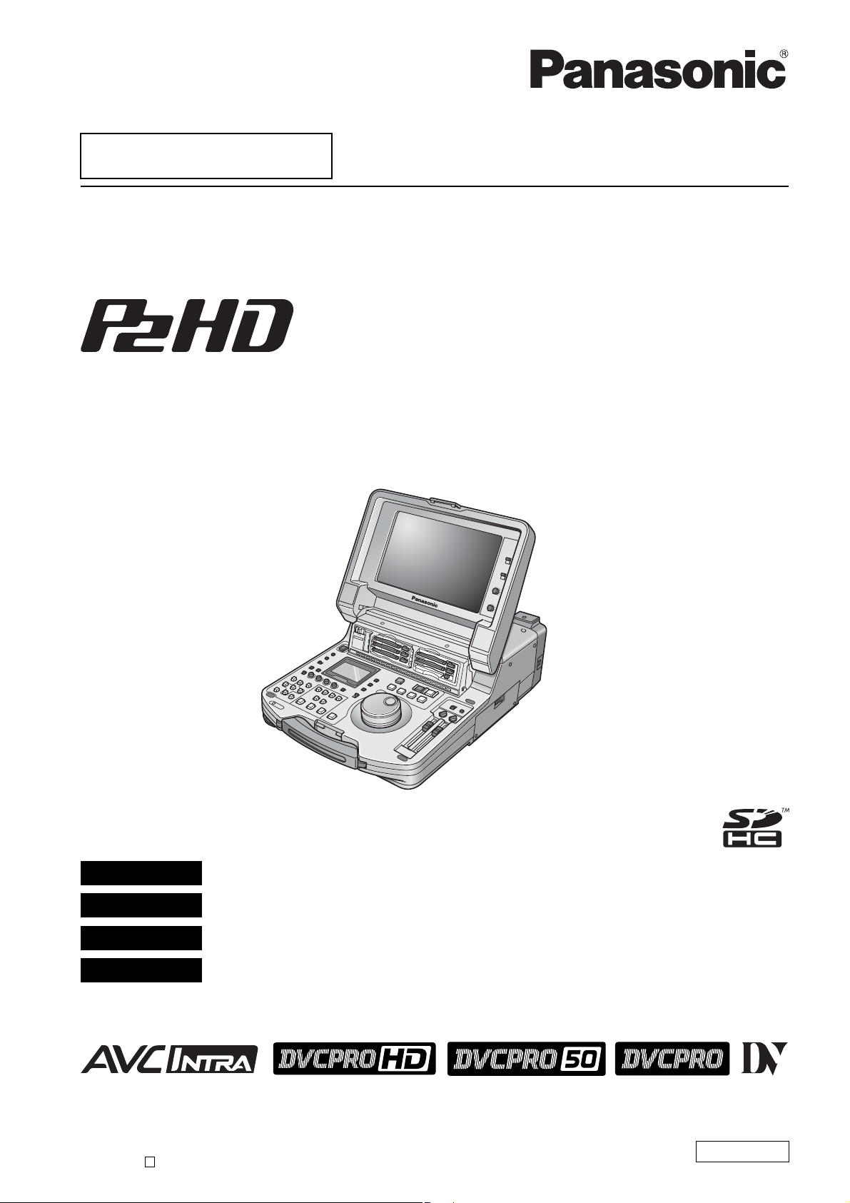
Memory Card Portable Recorder/Player
Operating Instructions
Model No. AJ-HPM110P
Model No. AJ-HPM110E
DEUTSCH Für Erlauterungen in Deutsch, konsultieren Sie bitte die mitgelieferte CD-ROM.
FRANÇAIS Pour des explications en français, veuillez vous reporter au CD-ROM fourni.
ITALIANO Per le istruzioni in italiano, vedere il CD-ROM in dotazione.
ESPAÑOL Para la explicación en español, consulte el CD-ROM uministrado.
Before operating this product, please read the instructions carefully and save this manual for future use.
• AVC-Intra capability is available when the optional AVC-Intra Codec board AJ-YBX200G is installed to the unit.
S1207T0 -P
Printed in Japan
D
ENGLISH
VQT1Q19
Page 2
Read this first!
For AJ-HPM110P
■ THIS EQUIPMENT MUST BE GROUNDED
To ensure safe operation, the three-pin plug must be
inserted only into a standard three-pin power outlet which is
effectively grounded through normal household wiring.
Extension cords used with the equipment must have three
cores and be correctly wired to provide connection to the
ground. Wrongly wired extension cords are a major cause
of fatalities.
The fact that the equipment operates satisfactorily does not
imply that the power outlet is grounded or that the
installation is completely safe. For your safety, if you are in
any doubt about the effective grounding of the power outlet,
please consult a qualified electrician.
CAUTION:
THE MAINS PLUG OF THE POWER SUPPLY
CORD SHALL REMAIN READILY OPERABLE.
THE AC RECEPTACLE (MAINS SOCKET
OUTLET) SHALL BE INSTALLED NEAR THE
EQUIPMENT AND SHALL BE EASILY
ACCESSIBLE.
TO COMPLETELY DISCONNECT THIS
EQUIPMENT FROM THE AC MAINS,
DISCONNECT THE MAINS PLUG FROM THE AC
RECEPTACLE.
WARNING:
• TO REDUCE THE RISK OF FIRE OR SHOCK
HAZARD, DO NOT EXPOSE THIS EQUIPMENT
TO RAIN OR MOISTURE.
• TO REDUCE THE RISK OF FIRE OR SHOCK
HAZARD, KEEP THIS EQUIPMENT AWAY
FROM ALL LIQUIDS. USE AND STORE ONLY
IN LOCATIONS WHICH ARE NOT EXPOSED TO
THE RISK OF DRIPPING OR SPLASHING
LIQUIDS, AND DO NOT PLACE ANY LIQUID
CONTAINERS ON TOP OF THE EQUIPMENT.
CAUTION:
TO REDUCE THE RISK OF FIRE OR SHOCK
HAZARD AND ANNOYING INTERFERENCE,
USE THE RECOMMENDED ACCESSORIES
ONLY.
CAUTION:
TO REDUCE THE RISK OF FIRE OR SHOCK
HAZARD, REFER MOUNTING OF THE
OPTIONAL INTERFACE BOARDS TO
QUALIFIED SERVICE PERSONNEL.
CAUTION:
This apparatus can be operated at a voltage in
the range of 100 – 240 V AC.
Voltages other than 120 V are not intended for
U.S.A. and Canada.
Operation at a voltage other than 120 V AC may
require the use of a different AC plug. Please
contact either a local or foreign Panasonic
authorized service center for assistance in
selecting an alternate AC plug.
CAUTION:
In order to maintain adequate ventilation, do not
install or place this unit in a bookcase, built-in
cabinet or any other confined space. To prevent
risk of electric shock or fire hazard due to
overheating, ensure that curtains and any other
materials do not obstruct the ventilation.
indicates safety information.
2
The rating plate is on the underside of this
equipment.
Page 3
Read this first! (continued)
For AJ-HPM110P
IMPORTANT SAFETY INSTRUCTIONS
1) Read these instructions.
2) Keep these instructions.
3) Heed all warnings.
4) Follow all instructions.
5) Do not use this apparatus near water.
6) Clean only with dry cloth.
7) Do not block any ventilation openings. Install in accordance with the manufacturer’s instructions.
8) Do not install near any heat sources such as radiators, heat registers, stoves, or other apparatus (including amplifiers) that
produce heat.
9) Do not defeat the safety purpose of the polarized or grounding-type plug. A polarized plug has two blades with one wider
than the other. A grounding-type plug has two blades and a third grounding prong. The wide blade or the third prong are
provided for your safety. If the provided plug does not fit into your outlet, consult an electrician for replacement of the
obsolete outlet.
10)Protect the power cord from being walked on or pinched particularly at plugs, convenience receptacles, and the point where
they exit from the apparatus.
11)Only use attachments/accessories specified by the manufacturer.
12) Use only with the cart, stand, tripod, bracket, or table specified by the manufacturer, or sold with the apparatus.
When a cart is used, use caution when moving the cart/apparatus combination to avoid injury from tip-over.
13)Unplug this apparatus during lightning storms or when unused for long periods of time.
14)Refer all servicing to qualified service personnel. Servicing is required when the apparatus has been damaged
in any way, such as power-supply cord or plug is damaged, liquid has been spilled or objects have fallen into
the apparatus, the apparatus has been exposed to rain or moisture, does not operate normally, or has been dropped.
S3125A
Notice (U.S.A. only):
This product has a fluorescent lamp that contains mercury. Disposal may be regulated in your community
due to environmental considerations. For disposal or recycling information, please contact your local
authorities, or the Electronic Industries Alliance: http://www.eiae.org.
IMPORTANT
Unauthorized recording of copyrighted television programmes, video tapes and other materials may
infringe the rights of copyright holders and contravene copyright laws.
<For USA-California Only>
This product contains a CR Coin Cell Lithium Battery which contains Perchlorate Material - special
handling may apply.
See www.dtsc.ca/gov/hazardouswaste.perchlorate.
3
Page 4

Read this first! (continued)
For AJ-HPM110P
FCC NOTICE (U.S.A.)
Declaration of Conformity
Model Number: AJ-HPM110P
Trade Name: PANASONIC
Responsible Party: Panasonic Corporation of North America
One Panasonic Way, Secaucus, NJ07094
Support contact: Panasonic Broadcast & Television Systems Company
1-800-524-1448
This device complies with Part 15 of FCC Rules.
Operation is subject to the following two conditions:
(1)This device may not cause harmful interference, and (2) this device must accept any interference received, including
interference that may cause undesired operation.
To assure continued compliance, follow the attached installation instructions and do not make any unauthorized
modifications.
Note:
This equipment has been tested and found to comply with the limits for a class B digital device, pursuant to Part 15 of the
FCC Rules. These limits are designed to provide reasonable protection against harmful interference in a residential
installation. This equipment generates, uses, and can radiate radio frequency energy, and if not installed and used in
accordance with the instructions, may cause harmful interference to radio communications. However, there is no guarantee
that interference will not occur in a particular installation. If this equipment does cause harmful interference to radio or
television reception, which can be determined by turning the equipment off and on, the user is encouraged to try to correct
the interference by
one of the following measures:
• Reorient or relocate the receiving antenna.
• Increase the separation between the equipment and receiver.
• Connect the equipment into an outlet on a circuit different from that to which the receiver is connected.
• Consult the dealer or an experienced radio/TV technician for help.
The user may find the booklet “Something About Interference” available from FCC local regional offices helpful.
Warning:
To assure continued FCC emission limit compliance, the user must use only shielded interface cables when connecting to
host computer or peripheral devices. Also, any unauthorized changes or modifications to this equipment could void the
user’s authority to operate this device.
4
Page 5
Read this first! (continued)
For AJ-HPM110E
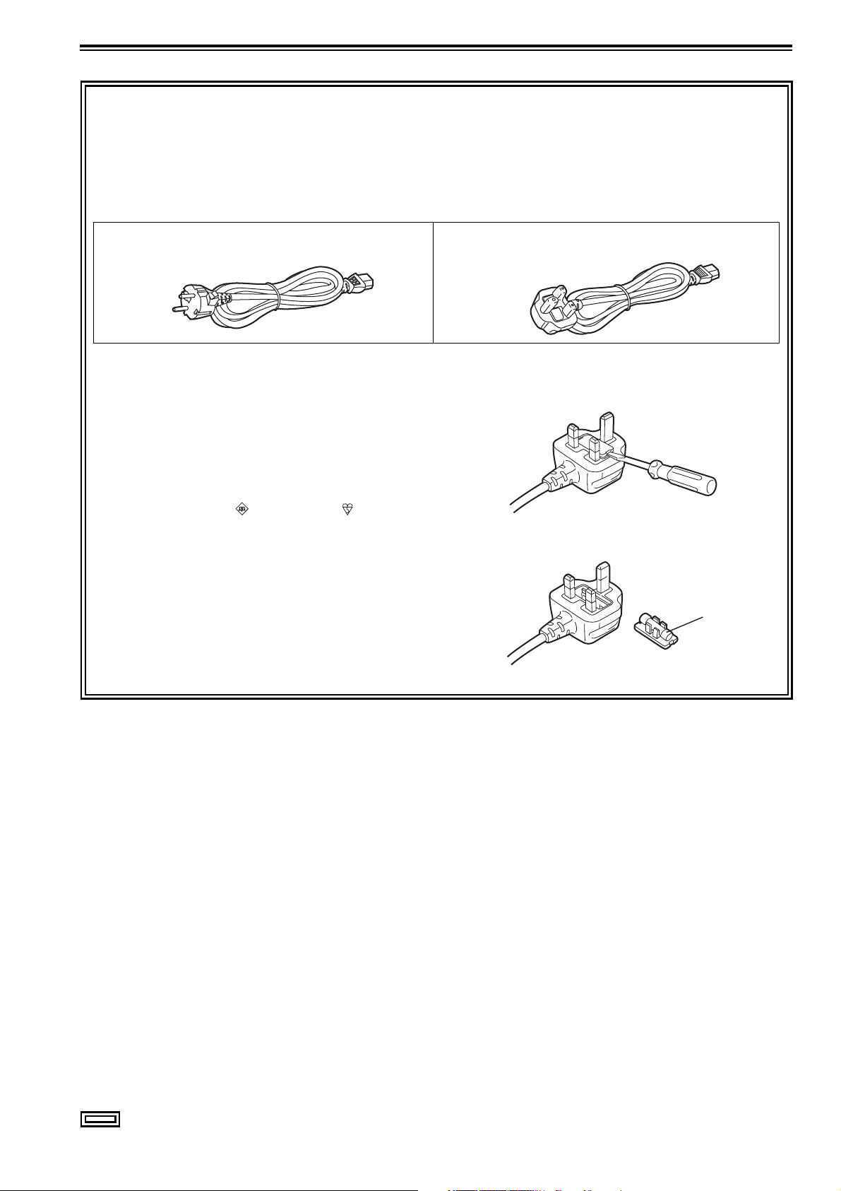
Caution for AC Mains Lead
FOR YOUR SAFETY PLEASE READ THE FOLLOWING TEXT CAREFULLY.
This product is equipped with 2 types of AC mains cable. One is for continental Europe, etc. and the other one is only for
U.K.
Appropriate mains cable must be used in each local area, since the other type of mains cable is not suitable.
FOR CONTINENTAL EUROPE, ETC.
Not to be used in the U.K.
FOR U.K. ONLY
This appliance is supplied with a moulded three pin mains
plug for your safety and convenience.
A 13 amp fuse is fitted in this plug.
Should the fuse need to be replaced please ensure that the
replacement fuse has a rating of 13 amps and that it is
approved by ASTA or BSI to BS1362.
Check for the ASTA mark or the BSI mark on the body
of the fuse.
If the plug contains a removable fuse cover you must ensure
that it is refitted when the fuse is replaced.
If you lose the fuse cover the plug must not be used until a
replacement cover is obtained.
A replacement fuse cover can be purchased from your local
Panasonic Dealer.
FOR U.K. ONLY
How to replace the fuse
1.Open the fuse compartment with a screwdriver.
2.Replace the fuse.
Fuse
indicates safety information.
5
Page 6
Read this first! (continued)
For AJ-HPM110E
■ THIS EQUIPMENT MUST BE EARTHED
To ensure safe operation, the three-pin plug must be
inserted only into a standard three-pin power point which is
effectively earthed through normal household wiring.
Extension cords used with the equipment must have three
cores and be correctly wired to provide connection to the
earth. Wrongly wired extension cords are a major cause of
fatalities.
The fact that the equipment operates satisfactorily does not
imply that the power point is earthed or that the installation
is completely safe. For your safety, if you are in any doubt
about the effective earthing of the power point, please
consult a qualified electrician.
■ DO NOT REMOVE PANEL COVERS BY
UNSCREWING THEM.
To reduce the risk of electric shock, do not remove the
covers. No user serviceable parts inside.
Refer servicing to qualified service personnel.
WARNING:
• TO REDUCE THE RISK OF FIRE OR SHOCK
HAZARD, DO NOT EXPOSE THIS EQUIPMENT
TO RAIN OR MOISTURE.
• TO REDUCE THE RISK OF FIRE OR SHOCK
HAZARD, KEEP THIS EQUIPMENT AWAY
FROM ALL LIQUIDS. USE AND STORE ONLY
IN LOCATIONS WHICH ARE NOT EXPOSED TO
THE RISK OF DRIPPING OR SPLASHING
LIQUIDS, AND DO NOT PLACE ANY LIQUID
CONTAINERS ON TOP OF THE EQUIPMENT.
CAUTION:
TO REDUCE THE RISK OF FIRE OR SHOCK
HAZARD AND ANNOYING INTERFERENCE,
USE THE RECOMMENDED ACCESSORIES
ONLY.
CAUTION:
TO REDUCE THE RISK OF FIRE OR SHOCK
HAZARD, REFER MOUNTING OF THE
OPTIONAL INTERFACE BOARDS TO
QUALIFIED SERVICE PERSONNEL.
CAUTION:
In order to maintain adequate ventilation, do not
install or place this unit in a bookcase, built-in
cabinet or any other confined space. To prevent
risk of electric shock or fire hazard due to
overheating, ensure that curtains and any other
materials do not obstruct the ventilation.
CAUTION:
THE MAINS PLUG OF THE POWER SUPPLY
CORD SHALL REMAIN READILY OPERABLE.
THE AC RECEPTACLE (MAINS SOCKET
OUTLET) SHALL BE INSTALLED NEAR THE
EQUIPMENT AND SHALL BE EASILY
ACCESSIBLE.
TO COMPLETELY DISCONNECT THIS
EQUIPMENT FROM THE AC MAINS,
DISCONNECT THE MAINS PLUG FROM THE AC
RECEPTACLE.
The rating plate is on the underside of this
equipment.
IMPORTANT
Unauthorized recording of copyrighted television programmes, video tapes and other materials may
infringe the rights of copyright holders and contravene copyright laws.
Operating precaution
Operation near any appliance which generates strong magnetic fields may give rise to noise in the video and audio signals.
If this should be the case, deal with the situation by, for instance, moving the source of the magnetic fields away from the unit
before operation.
Attention
Battery is used for the memory back-up in the
product.
At the end of its useful life, you should not throw it
away.
Instead, hand it in as small chemical waste.
indicates safety information.
Attentie
Voor het reservegeheugen van het apparaat
wordt gebruik gemaakt van een batterij.
Wanneer de batterij uitgeput is, mag u deze niet
gewoon weggooien, maar dient u hem als klein
chemisch afval weg te doen.
6
Page 7

Contents
Accessories ...............................................................................................12
Included Accessories ................................................................................. 12
Optional Accessories .................................................................................. 12
Opening and Closing the Top Panel ..........................................................13
Introduction Features .....................................................................................................14
Control Reference Guide ...........................................................................17
Audio and Video Controller ......................................................................... 17
GUI Operations ...........................................................................................21
Panel Control Unit and Card Slots .............................................................. 24
LCD Panel ................................................................................................... 25
Rear Panel ................................................................................................... 26
Side Panel ...................................................................................................30
Moving Between Screens and Menu Operations .......................................31
Operating Modes ........................................................................................31
Menu Operations .........................................................................................32
Using the On-screen Keyboard ..................................................................33
Using the Full Keyboard .............................................................................. 33
Using the Ten Keypad ................................................................................ 33
Recording, Playback and P2 Card Handling ..............................................34
Insert a P2 Card .......................................................................................... 34
Recording and Playback .............................................................................34
LOOP REC Function .................................................................................... 35
Removing P2 Cards .................................................................................... 36
Preventing Accidental Deletion ................................................................... 37
Connections ...............................................................................................38
Example of connections in 23.98/24/29.97/25 Hz mode ............................38
Example of connections for remote control ................................................ 38
Recording From a Variable Frame-Rate Camera ......................................39
Recording HD SDI output signals from a variable frame-rate camera as
720/23.98p ............................................................................................. 39
Recording HD SDI signals output by an HD camera as 1080/23.98p
(requires optional accessories) ............................................................. 40
Jog and Shuttle Operations Using the Search Dial ....................................41
Jog Mode ....................................................................................................41
Shuttle Mode (SHTL Mode) ......................................................................... 41
Clip Management Thumbnail and Clip Management ..............................................................42
Thumbnail Screen Names and Functions ................................................... 43
Changing Thumbnail Display ...................................................................... 45
Thumbnail editing ........................................................................................ 47
Selecting Clips ...........................................................................................48
Playing Back Clips .....................................................................................49
Playing Back Single Clips ...........................................................................49
Attaching Text Memos and Shot Marks .....................................................50
Attaching Text Memos ................................................................................ 50
7
Page 8

Attaching Shot Marks .................................................................................. 51
Copying Clips ............................................................................................ 52
Deleting Clips ............................................................................................ 53
Repairing and Reconnecting Clips ............................................................ 54
Repairing Bad Clips .................................................................................... 54
Reconnecting Incomplete Clips .................................................................. 54
Viewing and Revising Clip Information ..................................................... 55
Viewing Clip Information ............................................................................. 55
Revising Clip Metadata ............................................................................... 56
Attaching Metadata to Clips ...................................................................... 58
Preparing a Metadata Upload File .............................................................. 58
Setup to Attach Metadata ........................................................................... 58
Loading Set Metadata Values .....................................................................60
Recording Clips Containing Metadata ........................................................61
Formatting P2 Cards ................................................................................. 63
Checking Card Status ............................................................................... 64
Selecting Information to Display .................................................................64
Displaying Card Status Information ............................................................. 65
Using Play List Play List Function ...................................................................................... 67
Play List Screen Names and Functions ......................................................68
Buttons Used in Play List Operations ..........................................................70
Stop Mode Setup ........................................................................................73
Creating Play Lists .................................................................................... 74
Preparing New Play Lists ............................................................................ 74
Audio Channel Replacement During Editing .............................................. 75
Registering Events for Selected Clips .........................................................75
Registering Events From Video ...................................................................76
Importing and Adding to Existing Play List Files .........................................77
Saving Play Lists ....................................................................................... 78
Naming Play Lists ........................................................................................78
Saving a Play List to a P2 Card ................................................................... 78
Editing Play Lists ....................................................................................... 80
Opening an Existing Play List File ............................................................... 80
Changing Event IN and OUT Points ............................................................81
Trimming Events ..........................................................................................81
Changing Event Order ................................................................................ 82
Deleting Events ...........................................................................................83
Saving Events ..............................................................................................84
Deleting Play Lists .................................................................................... 85
Overwrite Editing of Play Lists .................................................................. 86
Preparing for Event Overwriting .................................................................. 86
Copying Event Audio to EXTRA track ......................................................... 87
Selecting Write Location and Audio/Video to Import ..................................87
Temporary Registration and Revision of Events ......................................... 88
Previewing and Adjusting Sound Volume ................................................... 89
Finalizing Overwrite Editing .........................................................................89
Recalling Events .......................................................................................... 90
8
Page 9

Audio Split Editing ......................................................................................91
Registering From Video ............................................................................... 92
Adding and Registering Audio Split Point (Changing Registered Point) .... 93
Trimming the Audio Split Point ....................................................................93
Cancelling an Audio Split Setting ................................................................94
Simplified Voice-Over ................................................................................95
Preparing for Voice-Over ............................................................................95
Voice-Over From Still Image Status ............................................................ 96
Voice-Over From Playback Status .............................................................. 96
Displaying Voice-Over Events .....................................................................97
Changing the Trimming of Audio Recording Location ................................ 97
Viewing Event Information .........................................................................98
Indicating Event Property ............................................................................ 98
Event Review ............................................................................................... 99
Playing Back Play Lists ............................................................................100
Setting the Playback Time Code (TC) .......................................................100
Playing Back the Play List .........................................................................101
Creating New Clips From the Play List (Edit Copy) .................................102
Using USB Connectors and
SD/SDHC Memory Cards
Using USB Connectors ............................................................................103
Using the Unit as a USB Host ................................................................... 103
Using the Unit as a USB Device ............................................................... 103
Connecting a PC to This Unit ...................................................................104
Switching to USB Device Mode ................................................................ 104
Using This Unit With a Hard Disk .............................................................105
Supported Hard Disks ............................................................................... 105
Switching to USB Host Mode .................................................................... 106
Formatting Hard Disks ..............................................................................106
Exporting to a Hard Disk in Card Units ..................................................... 107
Displaying Hard Disk Information (Explorer Screen) ................................ 108
Displaying Clip Thumbnails on a Hard Disk .............................................109
Importing Data from the Hard Disk to a P2 Card ......................................110
Using SD/SDHC Memory Cards ..............................................................111
Displaying Miscellaneous SD Memory Card Information ..........................111
Formatting SD Memory Cards ...................................................................111
External Remote Control ..........................................................................113
Remote operation of external devices ...................................................... 113
Automatic Recording of Cards .................................................................. 114
Setup Unit Setup ................................................................................................115
Changing Settings ...................................................................................116
Change Operations ................................................................................... 116
Using a Lock to Protect the User Setting File ........................................... 117
Returning to Factory Defaults (Initial Settings) .......................................... 117
Item Settings ............................................................................................118
SYSTEM ..................................................................................................... 118
BASIC ........................................................................................................ 120
9
Page 10

OPERATION .............................................................................................. 125
INTERFACE ...............................................................................................127
TIME CODE ............................................................................................... 128
VIDEO ........................................................................................................ 130
AUDIO ....................................................................................................... 135
DIF .............................................................................................................138
MENU ........................................................................................................ 139
Saving Menu Settings to SD Memory Cards .............................................140
Time Code, User Bit and CTL ................................................................. 142
Superimpose Screen .............................................................................. 146
List of Compatible Input and Output Formats ......................................... 147
Audio V Fade Function ........................................................................... 149
Audio Recording Channels Selection ..................................................... 150
Audio Recording Channels ....................................................................... 150
For Long and Trouble-Free
Operation
Condensation .......................................................................................... 151
Maintenance ........................................................................................... 151
Error Messages ....................................................................................... 152
WARNING information display ..................................................................153
“HOURS METER” information display .......................................................159
List of Shortcuts ......................................................................................... 160
Updating the Firmware in This Unit ......................................................... 162
Handling P2 Card Recording .................................................................. 163
Specifications ....................................................................................................................................................... 164
Menu index ........................................................................................................................................................... 167
10
Page 11

■ Information on software for this product
1. Included with this product is software licensed under the GNU General Public License (GPL) and GNU Lesser General Pub-
lic License (LGPL), and users are hereby informed that they have the right to obtain, change and redistribute the source
codes of this software.
Details on GPL and LGPL can be found on the installation CD provided with the unit. Refer to the folder called “LDOC”.
(Details are given in the original (English-language) text.)
To obtain the source codes, go to the following home page:
https://eww.pavc.panasonic.co.jp/pro-av/
The manufacturer asks users to refrain from directing inquiries concerning the source codes they have obtained and other
details to its representatives.
2. Included with this product is software which is licensed under MIT-License.
Details on MIT-License can be found on the installation CD provided with the unit. Refer to the folder called “LDOC”.
(Details are given in the original (English-language) text.)
■ Panasonic makes no guarantees for your recordings
Please understand that Panasonic makes no guarantees for your recordings in cases where images and/or sound were not re-
corded as you intended due to problems with this unit or P2 cards.
■ What to remember when throwing memory cards away or transferring them to others
Formatting memory cards or deleting data using the functions of the unit or a computer will merely change the file management
information: it will not completely erase the data on the cards. When throwing these cards away or transferring them to others,
either physically destroy them or use a data deletion program for computers (commercially available) to completely erase the
data. Users are responsible for managing the data on their memory cards.
■ Place of Installation
Do not install this unit in a location exposed to direct sunlight as this may deform the cabinet or damage the LCD screen.
■ Liquid crystal displays
• While 99.99% or more of the pixels on an LCD screen will function normally, 0.01% may either be dead or constantly lit (seen
as red, blue or green dots). This is not a malfunction.
• There may be some unevenness on the screen depending on the image displayed.
• Wiping or rubbing the LCD screen with a rough cloth may damage it.
• Leaving an unchanging image on the screen for a long period of time may create a temporary afterimage (burn-in).
• LCD response and brightness vary with ambient temperature.
• In a high-temperature and high-humidity location, the LCD panel characteristics may change and result in uneven image quality.
*SDHC logo is a trademark.
11
Page 12

Accessories
Included Accessories
Power cord ................................................... 1 (AJ-HPM110P)
2 (AJ-HPM110E)
CD-ROM ................................................................................ 1
Ferrite core* ........................................................................... 4
* Attach a ferrite core at each cable end when making cable connections to the USB2.0 connector.
Optional Accessories
• AVC-Intra Codec board
AJ-YBX200G
◆ NOTE:
• Do not use optional boards other than the above product.
Accessories
12
P2HD 5 Year Warranty Repair Program*
1
Thank you for purchasing this Panasonic P2HD device.
Register as a user for this device to receive a special service warranty up to five years of free warranty repairs.
Customers who register as users on the website will receive a extended warranty repair valid for
up to five years.
1st year 2nd year 3rd year 4th year 5th year
P2HD device
*1: Please note that this extended warranty is not available in some countries/regions see web site below for details. *2: Not all models eligible
for extended warranty coverage. *3: The basic warranty period may vary depending on the country/region see enclosed warranty for warranty
coverage. *4: Not all repair work is covered by this extended warranty see enclosed warranty card for warranty coverage. *5: The maximum
warranty period may be adjusted depending on the number of hours the device has been used.
2
*
Basic warranty
3
*
Extended warranty repair
4
*
5
*
Free 5 years of Warranty Repairs
Make sure to save the “Registration Notice” e-mail
Purchase
P2 product
Register online
within 1 month
“Registration Notice”
e-mail sent
during the warranty period.
Details about user registration and the extended warranty: http://panasonic.biz/sav/pass_e
Please note, this is a site that is not maintained by Panasonic Canada Inc. The Panasonic Canada Inc. privacy policy does not apply and is not applicable in relation
to any information submitted. This link is provided to you for convenience.
Page 13
Opening and Closing the Top Panel
◆NOTE
• Take care to avoid pinching your fingers when opening and
closing the top panel.
• Check that the card lock is set to on before closing the top
panel. Be sure to set the card lock to on before closing the
top panel. Never use force to close it when the lock is not
set to on as this will damage the unit.
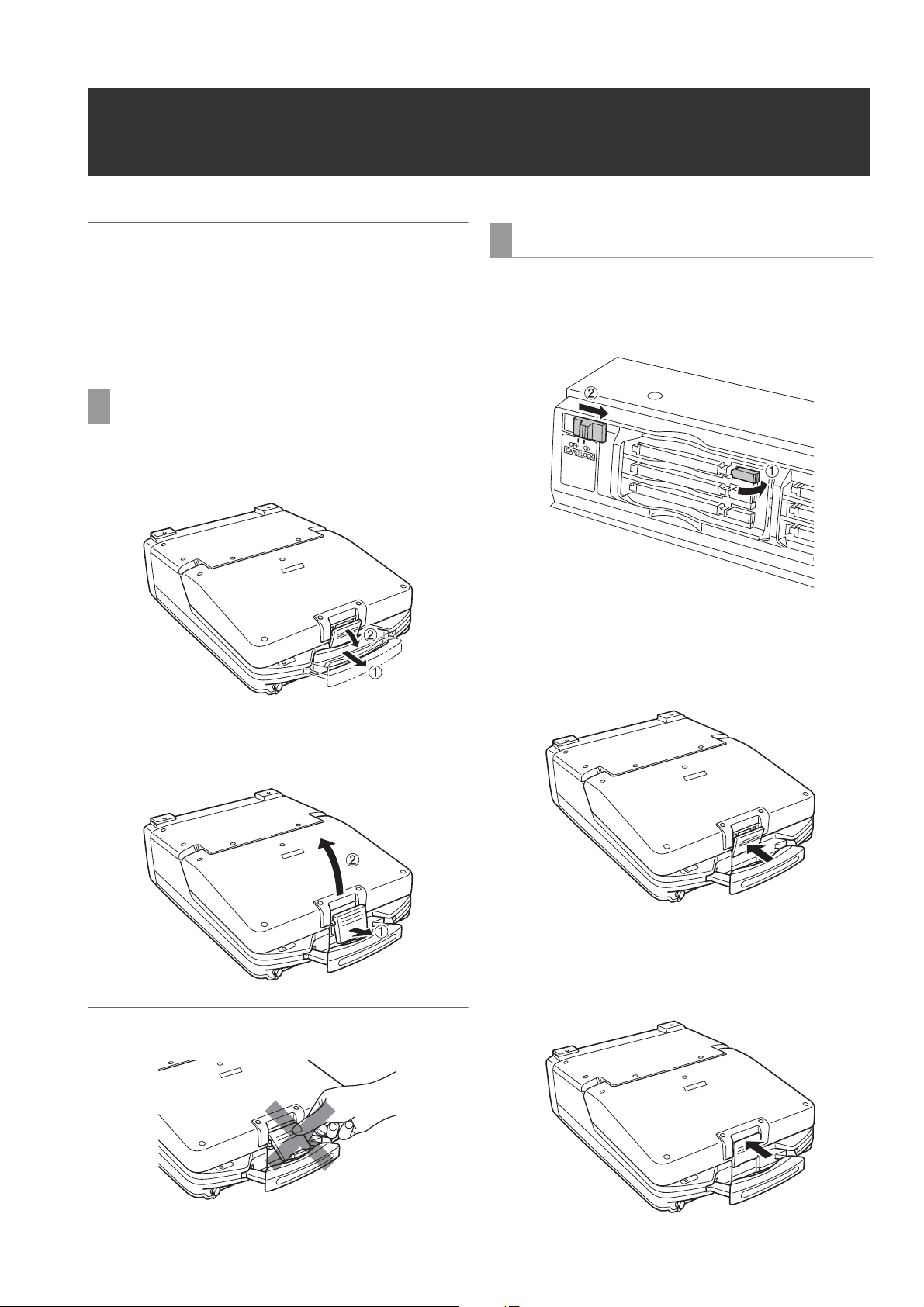
Opening the Top Panel
1 Pull out the handle, then pull the top of the lever to-
wards you to release the lock.
Closing the Top Panel
1 Make sure the EJECT button is folded downwards.
If not folded, fold the EJECT button to the right and set the
card lock to on.
2 Close the top panel and engage the bottom of the le-
ver with the receptacle in the lower portion of the pan-
el assembly.
2 Free the bottom of the lever. Then hold the top panel
and raise it to open.
◆NOTE
• Do not expose the lever to excessive force.
3 While making sure that the bottom of the lever has
been properly seated, press the top of the lever to-
wards the rear to lock it.
Opening and Closing the Top Panel
13
Page 14
Introduction
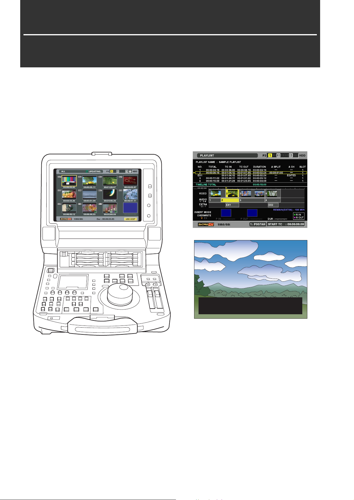
Features
The AJ-HPM110 is a portable memory card recorder/player equipped with six P2 card (*) slots and a 9-inch color LCD monitor.
Capability to record and play back audio and video in the compressed DVCPRO HD, DVCPRO50, DVCPRO/DV and AVC-Intra
(option) formats on six P2 cards (*) allows you to use the unit like a conventional editing VTR player. The AJ-HPM110 comes
with the following features.
MEMO: A memory card with the “P2” logo (for example, the separately sold AJ-P2C032RG) is referred to as a “P2 card” in this
manual.
T C R 0 0 : 0 1 : 2 3 : 0 1 E V 9 9
P S T O P
Introduction: Features
14
Page 15
■ Connecting a P2 Card Camera
A P2 card recorded in a P2 camera recorder plugs directly
into a PC card slot in this unit for immediate access. The P2
card is a semiconductor memory card that Panasonic
developed for professional AV use.
● P2 card and recording times
Recording time on a single 32 GB P2 card
HD mode
Video format
1080-59.94/
*2
50i
1080-30PN/
25PN (Native)
1080-24PN
(Native)
720-59.94P/
*2
50P
720-30PN/
25PN (Native)
720-24PN
(Native)
*1 Assumes installation of an AJ-YBX200G AVC-Intra Codec board.
*2 Includes recording of DVCPRO HD with pull-down at 30P, 24P and
25P.
Recording format and recording times
DVCPRO HD
Approx.
32 min.
---- Approx.
---- Approx.
Approx.
32 min.
Approx.
64 min.
Approx.
80 min.
AVC-Intra100*1AVC-Intra50
Approx.
32 min.
Approx.
64 min.
Approx.
32 min.
64 min.
Approx.
40 min.
Approx.
32 min.
Approx.
64 min.
Approx.
80 min.
80 min.
Approx.
64 min.
Approx.
128 min.
Approx.
160 min.
*1
SD mode
Video format
480-59.94i/
*4
576-50i
*3 For 2-channel audio recording
*4 Includes recording at 30P, 24P and 25P with pull-down.
Recording format and recording times
*3
DVCPRO 50 DVCPRO
Approx.
64 min.
Approx.
128 min.
DV
Approx.
128 min.
*3
◆ NOTE:
• This unit supports the following P2 cards.
·AJ-P2C004HG(4GB)
·AJ-P2C008HG(8GB)
·AJ-P2C016RG(16GB)
·AJ-P2C032RG(32GB)
(These are the card types that will available in January 2008. This
is subject to change with the introduction of cards of higher
capacity.)
This unit cannot use AJ-P2C002SG (2 GB) cards.
• The recording time of 16 GB, 8 GB and 4 GB P2 cards are 1/2, 1/4
and 1/8, respectively of that provided by a 32 GB P2 card.
■ Frame rate conversion
Recording input from variable frame-rate cameras at 24PN
(Native), the unit is also capable of playing back cards
recorded at 24 fps and converting the output to 1080/24 PsF.
It can also record input from a variable frame-rate camera at
25PN (Native).
◆ NOTE:
• Do not use cards that have been edited or contain clips shot in
different formats as the loss of management data may prevent
normal playback.
■ Native recording
The unit provides support for native recording, a mode that
records only active frames. This provides longer recording
time when a VariCam, AJ-HPX2000/2100 or AJ-HPX3000 is
connected to the HD-SDI IN connector. Variable frame rate
(VFR) recording becomes possible by connecting a VariCam.
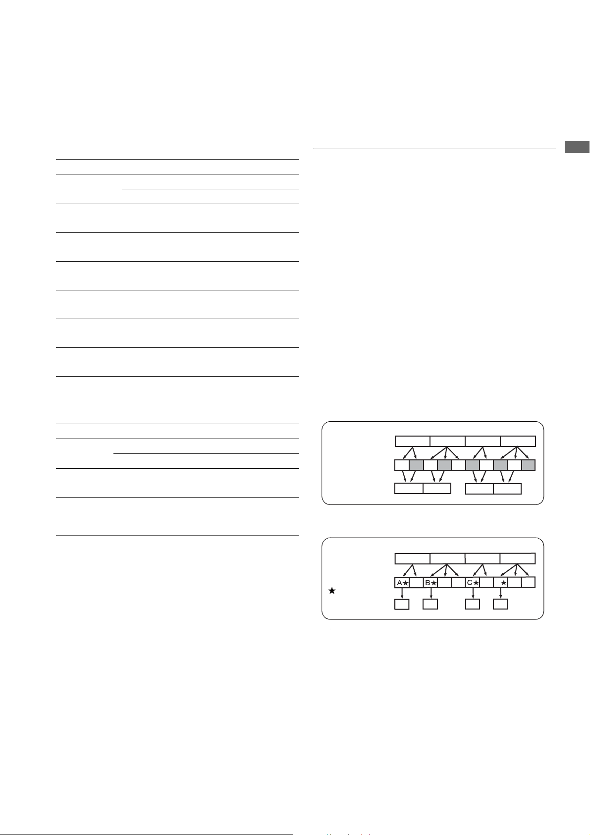
● Native recording defined
Native recording extracts only the active frames during 1080i
AVC-Intra (requires optional board) recording as well as 720P
DVCPRO HD and AVC-Intra (requires optional board)
recording. At 720P, this lengthens the recording time 2 to 2.5
times over pull-down recording.
Even during native recording at a system frequency of 59.94
Hz or 50 Hz, the unit will still produce pull-down output.
Example of 1080-24PN (Native)
Camera video
2:3 pull-down
Recording
Example of 720-24PN (Native)
Camera video
2:3 pull-down
Active frames
Recording
Ao Ae Bo Be Bo Ce Co De Do De
A C
A
■ Film-style cine-like gamma correction
The unit is capable of correcting video shot using the film-style
cine-like gamma mode provided by variable frame rate
cameras to create film-quality video.
BA C D
BA
B
BB
BA
C
DC
D
CD D D
D
Introduction
●
Visit the web site below and go to P2 support desk page for the
latest information on P2 card and SD/SDHC memory cards.
English: https://eww.pavc.panasonic.co.jp/pro-av/
■ 9-inch Wide LCD Monitor
A 9-inch wide LCD monitor is provided for ease of viewing HD
video.
Introduction: Features
15
Page 16

■ Dial Jog/Dial Shuttle
*1
The jog provides slow playback
+1.0.
The shuttle allows high-speed forward and reverse playback
up to 100 times normal speed. At speeds up to 10x, the sound
is also audible.
*1 When 59.94, 50, 29.97, 25 or 60-25 is selected in setup menu No.
25 SYSTEM FREQ.
■ Thumbnails for Managing Clips Visually
The 9-inch color LCD monitor on the front panel displays clips
(thumbnails) that represent P2 card content. Settings can be
made to show only specific clips in the thumbnail screen.
Clips selected from the thumbnail list can be played back
immediately, shot marks can be added, file data regarding the
clips can be confirmed and added and other clip
management operations are also available.
<About clips>
A clip is a single data item that contains video, audio,
metadata and other additional information. Normally, a clip is
one shot generated from the start of recording until recording
stops. However, when a shot spans multiple P2 cards, the
video on each card is handled as an independent clip. The
image at the start of recording appears in the thumbnail
screen as a representative image of that clip.
at rates between -1.0 to
■ Support for 59.94 Hz, 50 Hz, 23.98 Hz, 24 Hz and
25 Hz HD/SD
This unit can record and play back 59.94 Hz, 50 Hz, 23.98 Hz,
24 Hz and 25 Hz HD and SD video.
It can also handle analog video, SDI as well as IEEE1394 input
and output.
■ High-quality 8-channel digital audio
8-channel PCM audio where each channel (HD SDI has 8
independent channels while the analog interface has 4
independent channels) can be recorded separately or mixed.
■ Built-in up and down cross conversion
Built-in up and down cross conversion playback function is
provided as standard.
■ Menu-based Setup
Perform setup while viewing the setup menus on the 9-inch
color LCD monitor of this unit or a monitor TV display.
■ Hard Disk connection permits saving card data
to disk
Card data can be saved onto a hard disk that is equipped with
a USB 2.0 interface. Data stored on HDD can be written back
to a card. A USB 2.0 connection with a PC allows you to use
P2 cards inserted in the slots on this unit as mass storage.
This setup provides direct nonlinear editing.
■ Control of external devices
The RS-422A and IEEE1394 interfaces enable control of a
connected device. RS-422A enables automatic capture of
audio and video by specifying IN/OUT on an external device.
■ Creating Play Lists and the Playback Function
You can select video and audio recorded on the P2 cards
installed in the unit for playback in the desired order.
● A wealth of play list editing functions
• Audio IN point split: The play list makes it possible to move
the audio IN point forward or backward relative to the video
IN point.
• Voice-over: Separately recorded audio data can replace an
audio segment on one or two channels during playback.
• AV overwrite editing: This feature allows you to overwrite
edit and play back any audio and video segment (for 2
channels) on the play list.
■ Time code/Player function for editing provided
This unit has a built-in TCG (time code generator) and TCR
(time code reader). In addition to the internal time code,
external time code input or a VITC input signal can be
recorded as the time code.
The unit can also be used as a player for an editing system
using RS-422A.
■ AVC-Intra Codec Option Supported
The addition of an optional AVC-Intra Codec board AJ-
YBX200G will enable use of the AVC-Intra Codec.
Introduction: Features
16
Page 17
Control Reference Guide
PC
CONTROL
REMOTE
LOCAL
UNITY
4
2
2 4
UNITY
3
1
1 3
PB
CH
30
10
0
10
20
2/4
CH
1/3
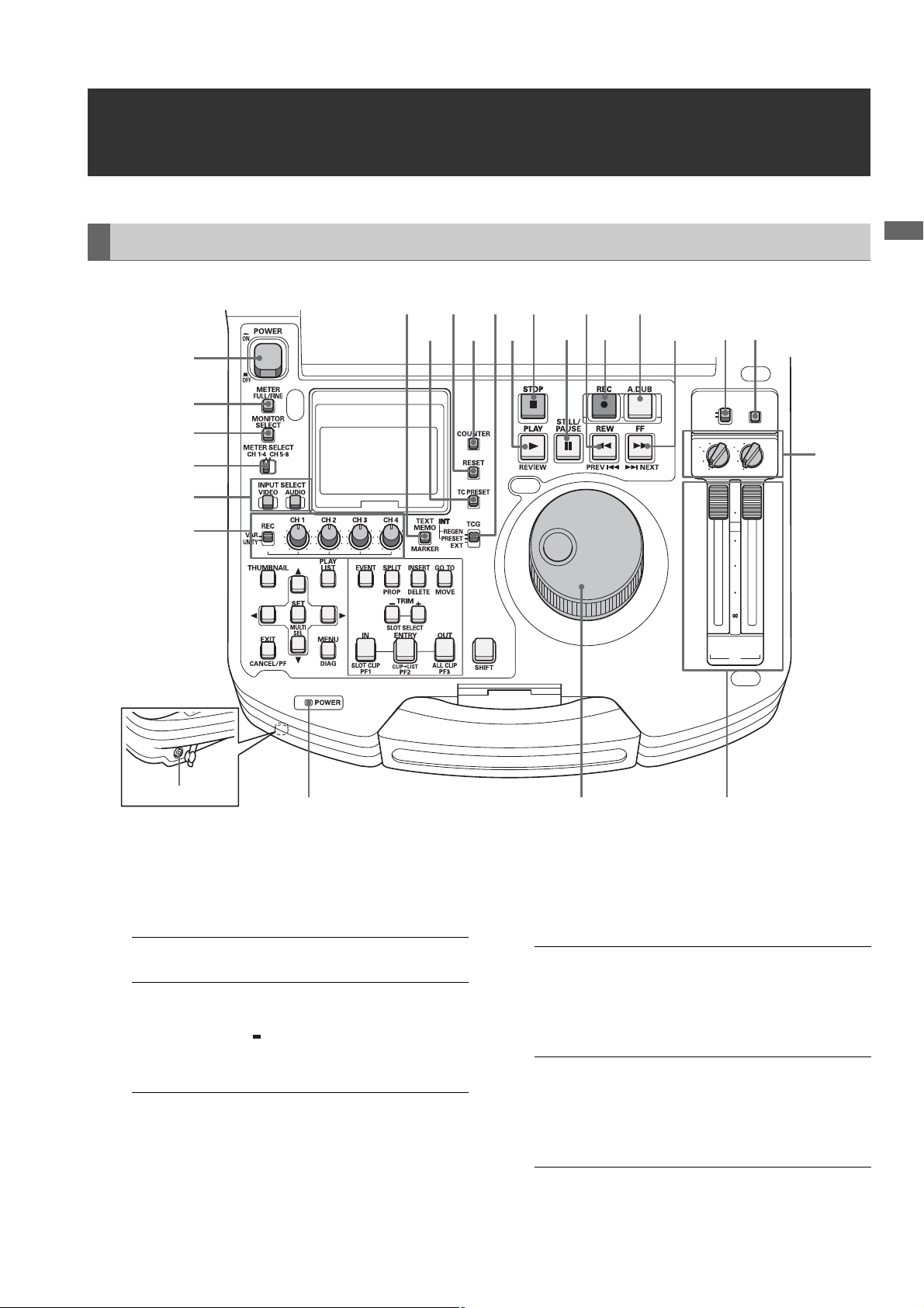
Audio and Video Controller
1
2
3
4
5
6
18
202224
19
2123 15
16
17
Introduction
14
1213 11
10
Headphones connector
1. POWER switch
Turns the power on and off.
2. METER (FULL/FINE) selector button
Switches the scale of the audio level meter.
FULL mode: Selects the standard scale
(– ∞ to 0 dB range)
FINE mode: Selects a scale divided into 0.5 dB
increments.
“ ” indicates reference level (as
set in setup menu) on a scale
divided into 0.5 dB increments.
3. AUDIO MONITOR SELECT button
Switches the audio signals to be output to the MONITOR L/R
connectors and the headphones jack. Each press of the
button switches the output signals to the MONITOR L/R
connectors and the headphones jack as described below.
When the METER
SELECT switch is set to
CH 1 to 4:
When the METER
SELECT switch is set to
CH 5 to 8:
(selectable only wi th HD
format)
The L/R lamps in the audio level meter indicate which
[CH1 / 2]➝[CH3 / 4]➝
[CH1 / 1]➝[CH2 / 2]➝
[CH3 / 3]➝[CH4 / 4]➝
[CH1+2 / 1+2]➝
[CH3+4 / 3+4]
[CH5 / 6]➝[CH7 / 8]➝
[CH5 / 5]➝[CH6 / 6]➝
[CH7 / 7]➝[CH8 / 8]➝
[CH5+6 / 5+6]➝
[CH7+8 / 7+8]
signal is selected.
987
Introduction: Control Reference Guide
17
Page 18

4. METER SELECT switch
Switches to CH1-4 or CH5-8 in the audio meter and the
monitor.
5. INPUT SELECT buttons
Switch between video and audio input signals. You
can also switch the input signals to internal signals
selected in setup menu No. 601 (VIDEO INT SG).
VIDEO: Each press of the VIDEO button switches
the input video signal in the following
order: [CMPST] ➝ [SDI] ➝ [1394] ➝ [SG].
When SG is selected, the signal switches
to the internal signal selected in setup
menu No. 601 (VIDEO INT SG).
AUDIO: Each press of the AUDIO button switches
the input audio signal in the following
order: [ANALOG] ➝ [SDI] ➝ [SG]. When
VIDEO is set to 1394, AUDIO is forcibly set
to 1394.
◆ NOTE:
• Switching of input signals is not available when the
THUMBNAIL and PLAY LIST buttons are on.
• The INPUT TRACK setting is available in overwrite mode
when the PLAY LIST button is on.
➝For details, refer to “Setting Tracks for Overwriting”
(page 87).
6. AUDIO REC VOL SEL switch
UNITY/VAR switch
UNITY: Records the audio signals at a fixed level
regardless of the positions of the audio
level controls.
VAR: Records audio signals at the level set with
the audio level controls.
9. Audio playback level controls
Adjust the playback level of audio signals (of channels
selected using the UNITY/VAR channel select switch).
However, they cannot adjust the playback level of
1394 output signals. CH5 to 8 are at all times played
back at a fixed level.
10.UNITY/VAR channel select switches
UNITY: Plays back audio signals at a fixed level
regardless of the positions of the audio
level controls.
1(2): Plays back and outputs audio CH1(2) at
the level adjusted using the audio level
controls to CH1(2) and at a fixed level to
CH3(4).
1+3
(2+4):
3(4): Plays back and outputs audio CH3(4) at
Plays back and outputs audio CH1(2) and
CH3(4) at the level adjusted using the
audio level controls to CH1(2) and CH3(4).
the level adjusted using the audio level
controls to CH3(4) and at a fixed level to
CH1(2).
11.PC button
Switches between the USB host mode for connecting
to a hard disk drive and the USB device mode for
connecting to a personal computer.
Press this button to open the mode selection screen on
the LCD monitor and select the desired mode.
➝For details, refer to “Using USB Connectors” (page
103).
12.CONTROL switch
Use this switch to enable remote control of this unit via
the 9-pin REMOTE.
Audio level controls
Use these controls to adjust the recording levels of the
audio signals (CH1/CH2/CH3/CH4). However, the
recording level cannot be adjusted during 1394 input.
7. POWER indicator
Lights when the power is on.
8. Search dial
Use to search and check video. Each press of the dial
alternates it between SHTL (shuttle) mode and JOG
mode. When the power is turned on, the search dial will
not operate unless it is first returned to the STILL
position.
Introduction: Control Reference Guide
18
13.FF/NEXT buttons
Press to fast forward. Select the speed in setup menu
No. 102 (FF. REW MAX). In the playback mode, hold
down the SHIFT button and press the FF button to
move to the beginning of the next clip.
During GUI display (thumbnail display and play list
display), hold down the SHIFT button and press the FF
button to move to the last thumbnail or event.
14.A. DUB button
Press this button to make a voice over recording in the
play list mode, or to overwrite copy an event audio to
an EXTRA track.
Page 19

➝For details, refer to “Simplified Voice-Over” (page
95), and “Copying Event Audio to EXTRA track”
(page 87).
15.REC button
Press this button and the PLAY button simultaneously
to start recording. Press this button during playback
mode to check EE mode video and audio on the
monitor (EE mode is not available during IEEE1394
input). Press the STOP button to return to the original
video and audio.
To start AUTO CAPTURE when the unit is controlled
from an external device, hold down the SHIFT button
and press the REC button.
➝Refer to “External Remote Control” (page 113).
16.REW/PREV button
Press to rewind. Select the speed in setup menu No.
102 (FF. REW MAX).
During playback, hold down the SHIFT button and
press the REW button to move to the beginning of the
current or previous clip.
During GUI display (thumbnail display and event list
display), hold down the SHIFT button and press the
REW button to move to the first thumbnail or event.
20.TCG switch
INT REGEN: The internal time code generator
synchronizes with the time code
read by the time code reader from
the P2 card. Select whether to make
TC or UB the REGEN in setup menu
No. 505 (TCG REGEN).
INT PRESET: Uses the internal time code
generator of this unit. Settings can
be preset on the operation panel
and the remote control panel.
➝Refer to “Time Code, User Bit and
CTL” (page 142).
EXT: Uses the external time code input
from the TIME CODE IN connector
or video signal VITC, SLTC, SVITC
and IEEE1394 digital input
connectors. Select in setup menu
No. 507 (EXT TC SEL).
21.COUNTER button
Press to switch the counter display of the LCD panel.
Each press of this button changes the counter display
as follows: [CTL (relative position from the beginning)]
➝ [TC (read time code)] ➝ [UB (user bit of the read
time code)].
Introduction
17.STILL/PAUSE button
Press this button to engage the search mode and
display a still picture. In the search mode, you can use
the search dial for JOG and SHTL (shuttle) operations.
18.STOP button
Press this button to stop. When the setting in setup
menu No. 122 (STOP EE SEL) is PB, you can monitor
still pictures and when set to EE, you can monitor input
video.
19.PLAY/REVIEW button
Press to start playback.
Press this button and the REC button simultaneously to
start recording.
When the play list is displayed, hold down the SHIFT
button and press this button to review (playback
starting 3 seconds before the IN point continuing to 1
second beyond the OUT point) an event at the pointer
position. The overwrite edit mode permits preview of
unfinalized events.
To play back the clip at the cursor location in the
thumbnail screen, hold down the SHIFT button and
press this button.
22.RESET button
Press this button when the LCD panel counter is in the
CTL mode to reset the counter display to [0:00:00:00].
Hold down the TC PRESET button and press this
button when the LCD panel counter is in the TC mode
(read time code) or UB mode (user bit of the read time
code) to reset the time code generator.
When using the on-screen keyboard, use this button to
delete all text, IN points in play lists, etc.
23.TC PRESET button
Set the TC (read time code) or UB (user bit of read time
code) value.
To make a setting, first press this button to change the
flashing digits. However, this function is not available
while in thumbnail mode, play list mode, and USB host
mode.
Introduction: Control Reference Guide
19
Page 20

24.TEXT MEMO/MARKER button
TEXT MEMO: Press this button during recording
and playback where you wish to
enter a text memo. In the thumbnail
screen, press this button to add a
text memo at the start of a clip.
➝For details, refer to “Attaching
Text Memos” (page 50).
MARKER: In the thumbnail screen, while
pressing the SHIFT button, press
this button to turn marker display of
the clip at the pointer position on
and off.
➝For details, refer to “Attaching
Shot Marks” (page 51).
Introduction: Control Reference Guide
20
Page 21
GUI Operations
PC
CONTROL
REMOTE
LOCAL
UNITY
4
2
2 4
UNITY
3
1
1 3
PB
CH
30
10
0
10
20
2/4
CH
1/3
1
2
3
4
15
16 14 13 12
Introduction
56
7 8 91011
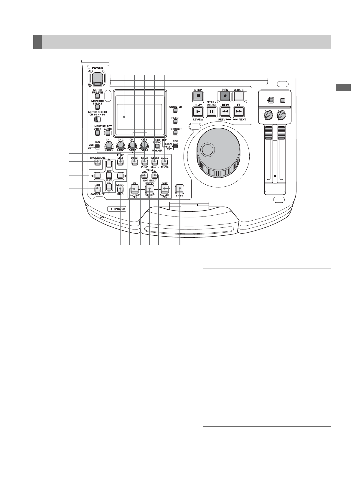
1. PLAY LIST button
Press to create play lists or to play a created play list.
The PLAY LIST button lights and the play list screen
appears on LCD panel or on a monitor output image.
Press again to exit the play list screen. The PLAY LIST
button goes off.
A play list menu setting makes it possible to select
whether ending playback in the play list screen should
return you to the play list screen or show a still image.
2. THUMBNAIL button
Press this button and the THUMBNAIL button lights
and the thumbnail screen appears on LCD panel or on
a monitor output image. Press again to exit the
thumbnail screen and return to the previous screen.
The THUMBNAIL button goes out.
3. Cursor buttons
The four outer buttons are cursor buttons and the
center button is the SET button. Use them to move the
cursor in menus, thumbnails, events, etc. to select
items.
4. EXIT/CANCEL/PF button
When the PLAY LIST/
THUMBNAIL buttons
are lit:
When the PLAY LIST/
THUMBNAIL buttons
are off:
Press to return to the
thumbnail display from
property. Selecting [EXIT]
in a menu has the same
effect as pressing the SET
button.
Hold down the SHIFT
button and this button
simultaneously to cancel
an action (for example,
canceling the selection of
an item).
Press this button and
buttons 6, 8 and 10 will
function as the PF1, PF2
and PF3 keys. Press this
button again before
pressing another button to
exit this mode.
Introduction: Control Reference Guide
21
Page 22

5. MENU/DIAG button
MENU button
Press this button to open the MENU. Press again to
return to the previous screen.
DIAG (SHIFT+MENU) button
Press to show information about this unit. Press again
to return to the previous screen. However, this function
is not available while thumbnails or play lists are
displayed.
Information about this unit includes [VIDEO SYSTEM],
[HOURSMETER], [WARNING], [UMID] and [DIF]. Use
the SET button or cross cursor buttons to switch
among them.
[VIDEO SYSTEM]
screen:
[WARNING] screen: Shows warning
[HOURS METER]
screen:
[UMID] screen: Shows UMID information
[DIF] screen: Shows various information
Shows current system
frequency, recording
format, input and output
formats and other
information.
information.
Shows the unit serial
number, the number of
hours it has been on, and
the number of times it has
been switched on and off.
for the current video.
on the current DIF (the
IEEE 1394 interface).
6. IN/SLOT CLIP/PF1 button
Use these functions to create play lists. Press the
ENTRY button and this button simultaneously when
registering an event (when the PLAY LIST button and
the EVENT button are both on) to set an event IN point.
Hold down this button and press the RESET button to
cancel the IN point of the selected event.
➝Refer to the Section “Using Play List” (page 67).
• Press the SHIFT button and this button
simultaneously while thumbnails are displayed to
switch the clip display between SELECTED and
specific SLOT.
• Press the ENTRY button and this button
simultaneously when the PLAY LIST button is off to
register a cue-up point.
• Press this button after the PF button when the
THUMBNAIL and PLAY LIST buttons are off to obtain
access to the setup menu registered using the PF1
button.
7. TRIM–/SLOT SELECT– button
Hold down the IN, OUT or SPLIT button and press this
button in play list mode to shift the IN, OUT and SPLIT
points 1 frame backward (4 frames at 24PN).
Hold down the SHIFT button and this button
simultaneously when the PLAY LIST button is off to
move to the previous recording slot position.Pressing
this button when the unit is in slot 1 results in a move to
slot 6.
8. ENTRY/CLIP (LIST/PF2 button)
Use these functions to create play lists.
Pressing the IN, OUT or SPLIT button simultaneous
with this button while registering an event (the PLAY
LIST and EVENT buttons are on), allows you to set the
IN, OUT and SPLIT points.
• Pressing the SHIFT button simultaneous with this
button in the play list mode allows you to add a clip
selected from a thumbnail display to the play list.
• Press this button after the PF button when the
THUMBNAIL and PLAY LIST buttons are off to obtain
access to the setup menu registered using the PF2
button.
9. TRIM+/SLOT SELECT+ button
Hold down the IN, OUT or SPLIT button and press this
button in play list mode to shift the IN, OUT and SPLIT
points 1 frame forward (4 frames at 24PN).
While the PLAY LIST button is off, hold down the SHIFT
button and this button simultaneously to move to the
previous recording slot position. Pressing this button
when the unit is in slot 6 results in a move to slot 1.
10.OUT/ALL CLIP/PF3 button
Use these functions to create play lists. Press the
ENTRY button and this button simultaneously when
registering an event (when the PLAY LIST button and
the ENTRY button are both on) to set an event OUT
point.
Hold down this button and press the RESET button to
cancel the OUT point of the selected event.
➝For details, refer to “Using Play List” (page 67).
• Press the SHIFT button and this button
simultaneously while thumbnails are displayed to
return the clip display to ALL.
• Press the ENTRY button and this button
simultaneously when the PLAY LIST button is off to
register a cue-up point.
Introduction: Control Reference Guide
22
Page 23

• Press this button after the PF button when the
THUMBNAIL and PLAY LIST buttons are off to obtain
access to the setup menu registered using the PF3
button.
11.SHIFT button
Use this button together with the FF, REW and SET
buttons.
12.GO TO/MOVE button
Use this button to move the IN, OUT, or SPLIT point of
events registered in a play list. It can also be used for
CUE UP when the THUMBNAIL and PLAY LIST buttons
are off. Hold down the IN/OUT button and press the
GO TO button to move and cue up to the IN and OUT
points. Hold down the SHIFT button and press this
button in the play list mode to move events.
➝For details, refer to “Using Play List” (page 67).
13.INSERT/DELETE button
Use this button to insert a new event between events in
the play list (when set to the insert edit mode).
Also use to select audio and video to overwrite event
audio and video (when set to the overwrite edit mode).
Hold down the SHIFT button and press this button
(DELETE) when thumbnails are displayed to delete a
selected clip.
In the play list, hold down the SHIFT button and press
this button to delete a selected event.
➝For details, refer to “Using Play List” (page 67).
The DELETE button allows you to perform on-screen
keyboard and file delete operations.
Use the EVENT button to enable control of an external
device connected to the unit via the RS-422A or
IEEE1394 interface when the THUMBNAIL and PLAY
LIST buttons are off.
➝Refer to “External Remote Control” (page 113).
16.LCD panel
➝For details, refer to “LCD Panel” (page 25).
Introduction
14.SPLIT/PROP button
Press the ENTRY button and this button simultaneously
in the play list register mode to register an event after
shifting the audio IN point relative to the video IN point.
Press the SHIFT button and this button simultaneously
during thumbnail, or play list display (when no menu is
displayed) to show the property of a clip or an event.
15.EVENT button
Press this button when the PLAY LIST button is on to
light the EVENT button. This engages the play list event
register/edit modes and allows you to set the IN, OUT,
and SPLIT points.
Press again to exit the event register/edit mode and
return to the previous screen. The EVENT button goes
out.
Introduction: Control Reference Guide
23
Page 24
Panel Control Unit and Card Slots
10
1
6
OFF ON
CARD LOCK
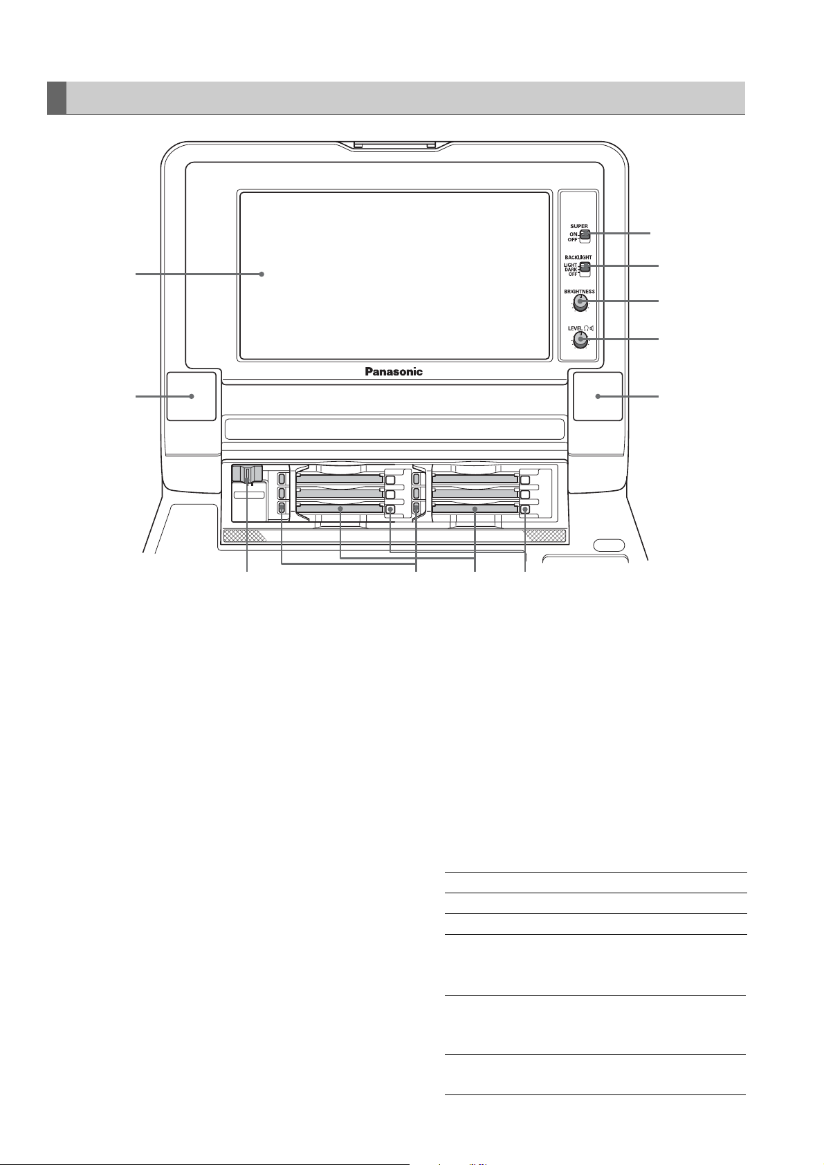
1. 9-inch Color LCD Monitor
Thumbnail screens facilitate video searches and
checks.
2. Card Lock
This lever locks the cards in place when the top panel
is closed. Set the lever to ON before closing the top
panel.
3. P2 Card Access LEDs
These LEDs indicate P2 card status.
➝For details, refer to “P2 Card Access LEDs and P2
Card Status” (page 35).
4. P2 Card Slots
Insert P2 cards into these slots.
Firmly insert the card until the EJECT button pops out.
After inserting a card, fold the EJECT button
downward.
9
8
7
6
5432
6. Stereo speakers
Outputs the audio monitor sound.
7. LEVEL control
Adjusts the sound volume of the internal speaker and
headphones.
8. BRIGHTNESS control
Adjusts the brightness of the LCD monitor.
However, it cannot adjust the brightness of time codes
and other superimposed indications.
9. BACKLIGHT switch
Switches the brightness of the LCD panel backlight as
shown below.
LIGHT: Bright
DARK: Dark
OFF: Turns the LCD off
5. EJECT button
Use this button to remove a P2 card inserted in a P2
card slot. Raise the button and press it in firmly. Do not
use the EJECT button when a P2 card access LED
flashes orange.
➝For details, refer to “P2 Card Access LEDs and P2
Card Status” (page 35).
Introduction: Control Reference Guide
24
10.SUPER switch
Switches the super output as follows.
ON: Outputs the time code and other
superimposed information to the LCD
monitor and monitor output image.
OFF: Does not output any superimposed
information.
Page 25
LCD Panel
6
dB dB dB dB
0
4
3
2
-12
1
1
0
-20
-1
-2
-3
-30
-4
-40
-
∞
L R L R L R L R
CTL
TC
UB
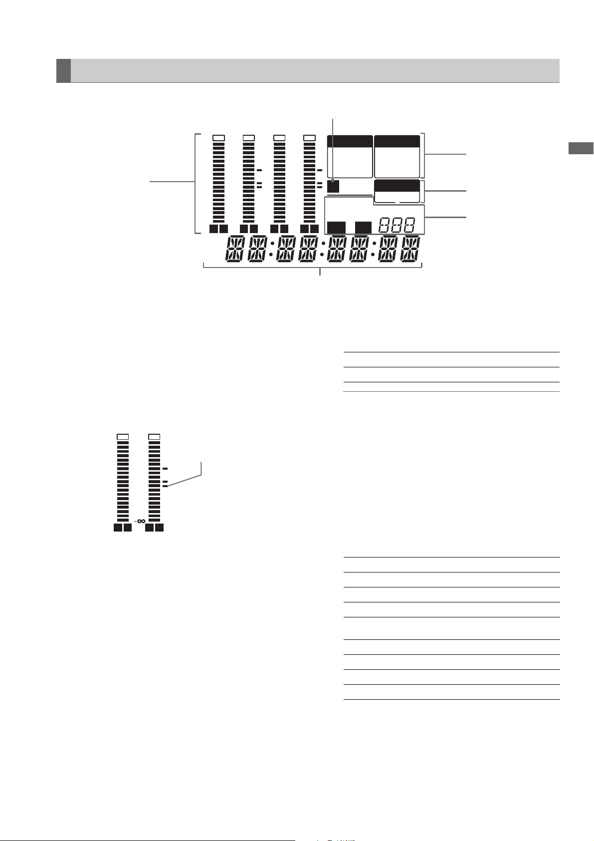
1. Level meter
Indicates the level of audio signals for CH1, CH2, CH3
and CH4.
The input signal level of audio signals is indicated
during recording and when EE is selected. During
playback the meter indicates output signal levels.
Use the METER selector button to switch the audio
level display to FULL mode or FINE mode. Use the
setup menu to change the reference level.
dB
0
-12
-20
-30
-40
FULL modeFINE mode
Reference level
LR
dB
4
3
2
1
0
-1
-2
-3
-4
LR
-1
-2
-3
-4
0
4
3
2
-12
1
0
-20
-30
-40
-
∞
VIDEO
CMPST
SDI
1394SG
U
1080i720p
DVCPRO
HD 50
AUDIO
ANALOG
SDI
1394SG
SYSTEM
59.9450
AVC-I
5
4
3
Introduction
4. TV system display
Indicates the selected TV system. Use the SYSTEM
setting in setup menu No. 25 SYSTEM FREQ to switch
between 59.94 Hz, 50 Hz or other settings.
59.94:
50:
Lights when a 59.94 Hz system frequency is selected.
Lights when a 50 Hz system frequency is selected.
◆ NOTE:
• When a frequency other than 59.94 Hz and 50 Hz is
selected, also the SYSTEM indicator goes off.
5. INPUT SELECT display
Indicates selected VIDEO and AUDIO status. Except
for analog audio signals, the indicator flashes when
there is no input for the selected signal.
When SDI input is selected, this display flashes if the
input signal is not compatible with the system format.
2. Counter display
This function shows the counter and time codes.
It displays CTL (relative position from the beginning),
TC (read time code) and UB (user bit of the read time
code).
3. Format display
Indicates the set record format and the format of video
recorded on an inserted P2 card.
VIDEO
CMPST: Analog composite video input signals
SDI: Serial digital video input signals
1394: IEEE1394 input signals
SG: Internal reference signals
AUDIO
ANALOG: Analog audio input signals
SDI: Serial digital audio input signals
1394: IEEE1394 input signals
SG: Internal reference signals
6. U lamp
In the EE mode, this lamp lights when an input signal
contains UMID information.
Lights during playback when the recording contains
UMID information.
Introduction: Control Reference Guide
25
Page 26
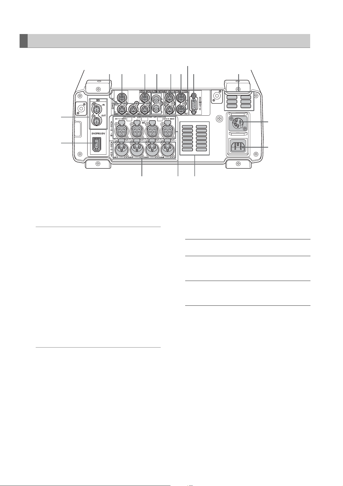
Rear Panel
9
85
101112131415
1
2
345
1. SERIAL DIGITAL COMPONENT AUDIO and VIDEO
IN/OUT connectors
These connectors enable input and output of serial
digital component audio and video signals.
◆ NOTE:
• The input digital audio signals must be synchronized with
the video input signals. Otherwise, the audio signals will be
affected by noise.
• Use a 5C-FB or equivalent double-shielded cable to make
connections to the SERIAL DIGITAL COMPONENT
connector.
2. IEEE 1394 digital input/output
This is an IEEE1394 digital interface. It inputs/outputs
IEEE1394 compressed digital signals that comply with
the IEC61883-1, IEC61883-2 and SMPTE396M
standards. Use 6-pin connectors. This connector does
not support bus power.
◆ NOTE:
• Use a double-shielded cable to make connections to the
IEEE1394 digital input/output connector.
• AVC-Intra 50 and AVC-Intra 100 (optional) recording and
playback do not support input/output via the IEEE 1394
connector.
• No input or output is available via the IEEE1394 connector
when something other than 59.94 or 50 is selected in setup
menu No. 25 SYSTEM FREQ.
7
6
4. ANALOG AUDIO IN connectors/impedance
switches/CH2 input switches
Analog audio input connectors
The input impedance of CH1-2 to CH3-4 can be
switched. The LINE, MIC and 48V switches make it
possible to use CH2 as a microphone input.
LINE: Line input for audio input signals from
audio device
MIC: Audio input signal from microphone with
internal power supply (this unit does not
provide phantom microphone power).
+48 V: Audio input signal from microphone with
external power supply (this unit provides
phantom microphone power).
5. Fan
Cools this unit. Install the unit making sure that the air
vents are not blocked. If the fan stops due to a
breakdown, “E-10” will appear on the counter display.
While the unit will operate even when the fan has
stopped, it should be shut down immediately.
6. AC IN socket
Connect the supplied power cord to a power outlet.
3. ANALOG AUDIO OUT connectors
Output analog audio signals.
Introduction: Control Reference Guide
26
Page 27
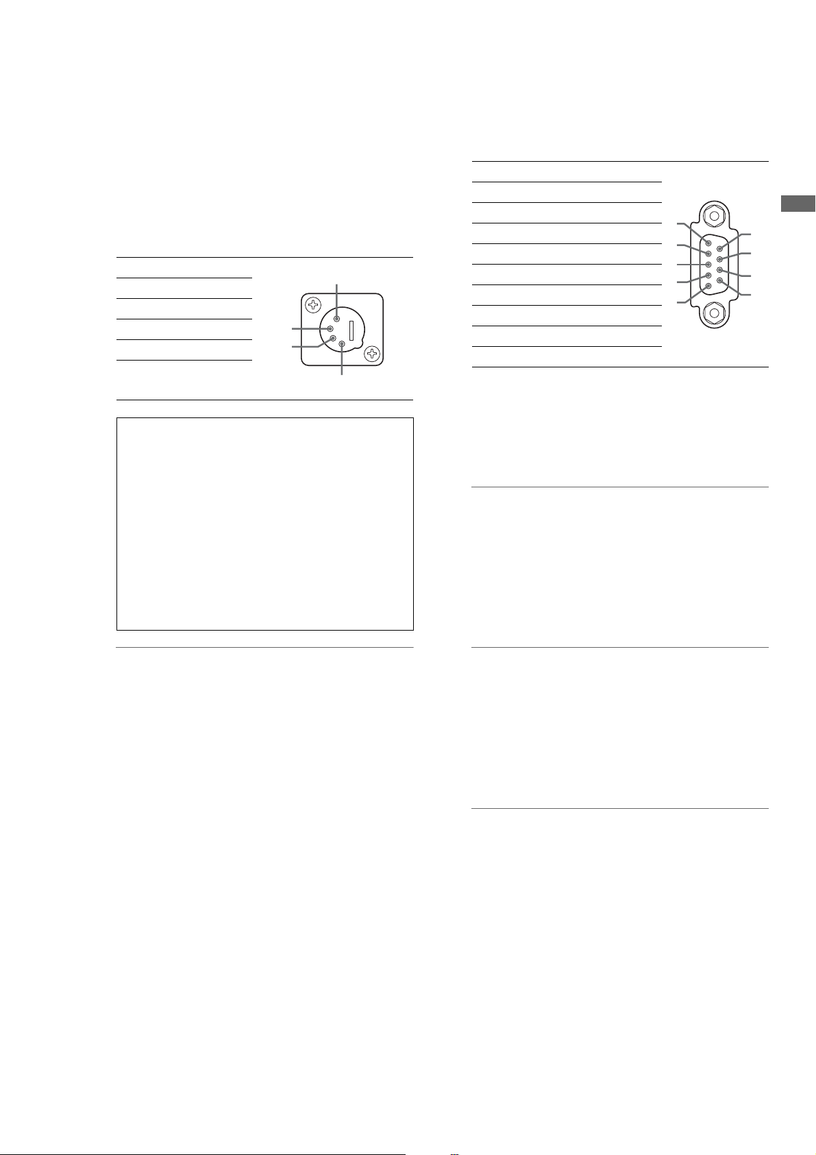
7. DC IN socket
Connect a 12 V DC power supply here. Use an external
12 V DC, 4.8 A (15 A peak or more) DC power supply.
When the voltage goes below approx. 10.6 V, the
power supply of this unit shuts down (when menu No.
180 BATTERY SEL is not “TYPE-A” or “TYPE-B”). The
unit does not automatically recover when the power
comes back on. First turn the POWER switch off, wait a
few seconds before turning the switch back on.
Pin No. Signal
1 Ground
2—
3—
4+12V
Be sure to check the rating of any external DC power
supply you intend to use to confirm that it is
compatible with this unit. Also check the pin
arrangement of the DC OUT socket of an external DC
power supply with the DC IN socket of this unit to
make sure the polarity is right.
Erroneously applying +12 V to the GND terminal
could cause a fire or lead to injuries.
Connecting a cord with incorrect polarity to the DC IN
connector of another device that is also connected to
this unit could lead to fire or injury.
2
3
8. Remote control connector
This unit can be connected to an external controller to
enable remote operation of the unit.
RS422A REMOTE IN/OUT (9P)
Pin No. Signal
1 FRAME GROUND
2 TRANSMIT A
3 RECEIVE B
4 RECEIVE COMMON
1
5—
6 TRANSMIT COMMON
7 TRANSMIT B
8 RECEIVE A
9 FRAME GROUND
1
2
3
4
5
Introduction
6
7
8
9
4
9. TIME CODE OUT connector
Outputs the playback time code during playback.
Outputs the time code generated by the internal time
code generator during recording.
◆ NOTE:
The TIMECODE OUT connector does not output a time
code when 23.98, 24, 29.97, 59-23, 60-24, 25 or 60-25
is set in setup menu No. 25 SYSTEM FREQ.
10.TIME CODE IN connector
Use to record an external time code onto P2 cards.
◆ NOTE:
• When using an external DC power supply, be sure to first
turn on the power to the DC power supply and then turn on
the POWER switch on this unit. If the order of the above
procedure is reversed, this unit will malfunction since the
voltage of an external DC power supply rises slowly.
• Inadvertently connecting an input of 18 V or more triggers
an internal protection circuit that shuts down the unit. The
unit will operate normally once the power voltage returns to
normal levels. Be sure not to connect an AC power supply
to this socket.
• When the external DC power supply is connected and set
to on, a minute amount of current will still flow even if the
POWER switch on this unit is set to OFF.
◆ NOTE:
The time code from the TIMECODE IN connector
cannot be input when 23.98, 24, 29.97, 59-23, 60-24,
25 or 60-25 is set in setup menu No. 25 SYSTEM FREQ.
11.REF VIDEO IN connectors
Input connectors for HD and SD reference video signals.
◆ NOTE:
• It is recommended that this unit be used with a system that
inputs a reference video signal since video and audio
output signals may otherwise deteriorate.
• Input tri-level sync signals with both positive and negative
polarities as HD reference video signals. Input signals that
meet the input signal and data format.
➝For information on the reference signal, refer to
“Example of connections in 23.98/24/29.97/25 Hz
mode” (page 38).
• Input a black burst signal that complies with SMPTE170M
and ITU624-4 to use for SD reference video signals.
Introduction: Control Reference Guide
27
Page 28

• When no cable is connected to REF VIDEO OUT connector,
the REF VIDEO IN connector is automatically terminated at
75 Ω. Connecting a cable to this connector releases
75 Ω termination.
• When 59-23, 60-24 or 60-25 is selected in setup menu
No. 25 SYSTEM FREQ, synchronization is provided only for
playback HD reference signals.
12.AUDIO MONITOR OUT connector
This connector outputs the audio signal (CH1, CH2,
CH3 and CH4) that is selected with the MONITOR
SELECT button.
13.ANALOG COMPOSITE MONITOR OUT connector
Outputs analog composite monitor video signals.
14.ANALOG COMPOSITE VIDEO IN connector
Inputs analog composite video signals.
15.ANALOG COMPONENT VIDEO OUT connectors
Inputs analog composite video signals during output
of HD signals. When SD is selected as the output
signal, three composite signals are output.
Setup menu 643 OUT MODE SEL determines the
signals that are output.
◆ NOTE:
• Use only shielded cable for cables (except the AC cable)
that are connected to the rear panel. Cables connected to
serial digital signal connectors (SDI IN/OUT connectors)
should be double shielded cables.
IEEE 1394 Digital Interface
■ Basic Setup
Make sure that setup menu No. 882 DIF IN CH and No. 883
DIF OUT CH on this unit are set to “AUTO.”
◆ NOTE:
• Only signals that comply with the format selected in setup menu No.
020 SYS FORMAT can be input. When the SYS FORMAT is 480i
(576i at 50 Hz), operations are limited to setup menu No. 024 REC
FMT (SD) settings.
• The selected recording format and the format of a recording on an
inserted P2 card determine the output format.
* Select CH1/CH2 or CH3/CH4 as the output audio channels (in
DVCPRO/DV).
• AV signals may be disrupted when connected devices are
turned on and off or when the interface cable is connected
or disconnected.
• It may take the system a few seconds to stabilize after
switching input signals or changing modes. Start recording
after the system has stabilized.
• The following applies to recordings made via the IEEE 1394
digital interface as well as to the signals it outputs.
- The audio level control knobs on the front panel do
not work.
- The settings in menu No. 680 and 681 regarding
blanking periods are ignored.
- Video and audio recording and EE type video and
audio of signal inputs other than 1x speed playback
signals are not guaranteed.
• The following applies to video input via the IEEE 1394 digital
interface.
- In the EE mode, SDI, analog video output signals
and time codes become irregular. Do not use these
signals for recording.
• Unprocessed video and audio signals are output via the
IEEE 1394 digital interface during SLOW and STILL
playback. When monitored on another device, these video
and audio signals may sound different than when played
back on this unit. Do not start up any other application
program when this unit is connected to other devices during
nonlinear editing. Such applications could adversely affect
the video output by such a device during nonlinear editing.
◆ NOTE:
Observe the following when connecting an IEEE 1394 cable
(separately sold). (An incorrect connection may damage this
unit or external devices.)
• Turn off all connected devices before connecting or disconnecting
IEEE1394 cables.
Connect all devices provided with a ground connector to ground (or
to a common ground).
• When connecting the unit to a device with a 4-pin connector,
connect the cable to the 6-pin connector on this unit first.
• Be sure to correctly connect an IEEE1394 cable to a connector.
• When connecting a cable to a 6-pin IEEE1394 connector, make sure
that it mates properly with the connector.
■ Precautions
• Connect this unit to only one other device.
• If the E-92 warning (1394 INITIAL ERROR) appears,
reconnect the connecting cable or turn the power off and
back on again.
Introduction: Control Reference Guide
28
Page 29
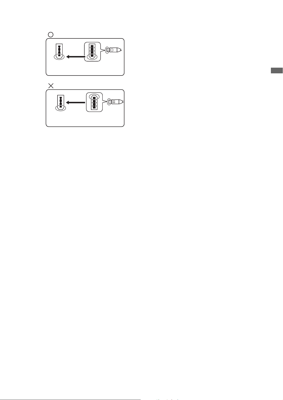
(This way)
IEEE1394
connector
IEEE1394
cable plug
(Not this way)
IEEE1394
connector
• When connecting this unit to an external device, first connect the
IEEE1394 cable to the external unit and then to this unit.
Connecting the cable to this unit first may damage it by the static
electricity generated.
• AVC-Intra 50 and AVC-Intra 100 (optional) recording and playback
do not support input/output via the IEEE 1394 connector.
• No input or output is available via the IEEE1394 connector when
something other than 59.94 or 50 is selected in setup menu No. 25
SYSTEM FREQ.
IEEE1394
cable plug
Introduction
Introduction: Control Reference Guide
29
Page 30
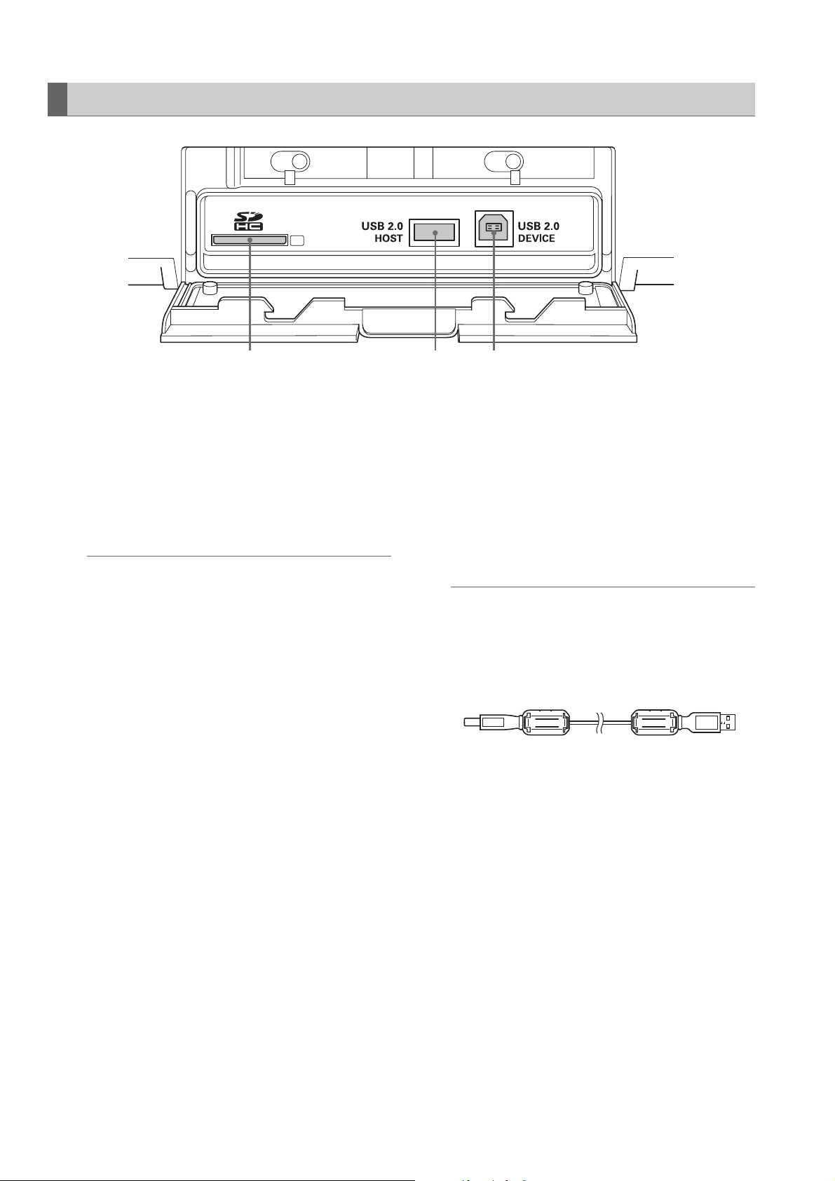
Side Panel
213
1. SD/SDHC Memory Card Slot
Insert an SD/SDHC memory card.
Insert the card with the label side facing up and the
end with the corner cut off facing in. Push in the card
until it locks into place. To remove the card, first make
sure that the lamp is not on, then push it in the direction
of insertion to release the lock.
◆ NOTE:
<Precautions in using SD/SDHC memory cards>
• Do not insert any cards other than SD/SDHC memory
cards.
• This unit uses only SD/SDHC memory cards that comply
with the SD/SDHC specifications. Other memory cards
such as MultiMediaCard cannot be used. When using a
miniSD card, be sure to use an adaptor dedicated for use
with the miniSD card to insert the card into the SD Memory
Card Slot.
* MultiMediaCard (MMC) is a registered trademark of
Infineon Technologies AG.
* The SDHC (SD High Capacity) card is a new standard,
established by the SD Card Association in 2006, for
large-scale memory cards with capacities above 2 GB.
• To format an SD card on a PC, use the following software
that can be downloaded from the support sites listed
below.
• This unit supports the following SD and SDHC memory
card capacities.
SD (8 MB to 2 GB): 8 MB, 16 MB, 32 MB, 64 MB, 128 MB,
256 MB, 512 MB, 1 GB, 2 GB
SDHC (4 GB to 16 GB): 4 GB, 8 GB, 16 GB
• For the latest information not available in the Operating
Instructions, visit the P2 support desk at the following Web
sites.
For English: https://eww.pavc.panasonic.co.jp/pro-av/
• The term “SD memory card” will be used below as a
generic for SD and SDHC memory cards.
2. USB 2.0 connector (Type A)
Connect P2 store and USB 2.0 compliant hard disk
drives for use in the USB host mode.
➝Refer to “Using USB Connectors” (page 103).
3. USB 2.0 connector (Type B)
Connect personal computers and other devices for
use in the USB device mode.
➝Refer to “Using USB Connectors” (page 103).
◆ NOTE:
• Use double shielded cable for making connections to USB
2.0 connectors.
• Attach the supplied ferrite cores near the cable connector
at each cable end when making cable connections to the
USB 2.0 connector.
Introduction: Control Reference Guide
30
Page 31

Moving Between Screens and Menu Operations
Operating Modes
This unit provide the three operating modes described below.
Use the THUMBNAIL and PLAY LIST buttons to select these
modes. Lamps indicate which mode is currently engaged.
PLAY LIST
Recording and playback modes
TCR 00 : 00 : 20 : 29
THUMBNAIL
Thumbnail mode
THUMBNAIL
PLAY LIST
EVENT
Recording and
playback modes
Displays video and performs
recording or playback.
Thumbnail mode Shows thumbnails of clips and
manages clips.
Play list mode Creates play lists. The play list
mode also provides the event
register mode screen (the PLAY
LIST and EVENT lamps light).
Off
On
Blinking
Stop
(STOP)
T C R 0 0 : 0 0 : 2 0 : 2 9
Playback (PB)
(PLAY, STILL,
FF, REW)
T C R 0 0 : 0 1 : 2 3 : 0 1 E V 9 9
S T O P
P L A Y
Introduction
Event register/edit modes
T C R 0 0 : 0 0 : 0 0 : 0 0 E V 0 1
P S T O P
Press STOP in STOP MODE =
RETURN to return to the play list
T C R 0 0 : 0 0 : 2 0 : 2 9
R P L A Y
When STOP MODE = STAY,
Press the EXIT or PLAYLIST button in the STOP mode to return to the play list.
INSERT, EVENT
Press IN/OUT/
SPLIT + ENTRY
to register or edit
an event.
STOP MODE
= upon RETURN: STOP
STOP MODE
= upon STAY: EXIT or
PLAYLIST
Playback(PB)
(PLAY, STILL, FF, REW)
THUMBNAILPLAY LIST
Play list
mode
Zoom in and zoom
out the timeline
Register the selected clip to an event
by pressing SHIFT + ENTRY.
INSERT
(upon OVERWRITE)
EVENT
Overwrite edit mode
T C R 0 0 : 0 0 : 0 0 : 0 0 E V 0 1
P S T O P
Introduction: Moving Between Screens and Menu Operations
31
Page 32

Menu Operations
Press the MENU button in each mode to open the menu.
Perform menu operations as described below.
3
1,42
1 Press the MENU button to open the menu.
2 Use the cursor buttons to place the cursor on menu
items.
◆ NOTE:
• Press the ▲ and ▼ buttons to move the cursor up and down.
• Press a to open a submenu.
• Press b or the EXIT button to return to a higher level.
3 Press the SET button.
◆ NOTE:
• Some menu items may display a confirmation screen.
• Use the cursor buttons to select a process and press the
SET button.
4 Press the MENU button to end processing.
◆ NOTE:
• Some menu items, when selected, will automatically return you
to the previous screen.
Introduction: Moving Between Screens and Menu Operations
32
Page 33

Using the On-screen Keyboard
Using the Full Keyboard
The full keyboard appears when necessary.
Move the cursor to the character you want to enter and press
the SET button.
Use the cursor buttons to move the cursor.
The keyboard keys have the functions listed below.
Key Function Shortcut keys
BS Deletes one character SHIFT+INS
Caps Toggles between upper and lower
case
OK Saves made entries and closes the
on-screen keyboard
EXIT Cancels made entries and closes the
on-screen keyboard
Moves the cursor to the first character SHIFT+REW
▲
▲
Moves the cursor 1 character space
▲
▲▲
back
Moves the cursor 1 character space
forward
▲
Moves the cursor to the location
after the last character
◆ NOTE:
• RESET deletes all entered characters.
• When you press the shortcut EXIT button, a confirmation message
appears. Select [YES] and press the SET button to close the on-
screen keyboard.
GO TO
ENTRY
EXIT
–
+
SHIFT+FF
Using the Ten Keypad
The ten keypad appears when necessary.
Move the cursor to the character you want to enter and press
the SET button.
Use the cursor buttons to move the cursor.
The keypad keys have the functions listed below.
Key Function Shortcut keys
BS Deletes one character SHIFT+INS
OK Saves made entries and closes the
soft keyboard
EXIT Cancels made entries and closes the
soft keyboard
<Decimal entries>
▲
Moves the cursor 1 character space
back
<Time code entries>
Moves the cursor 2 character spaces
▲
back
<Decimal entries>
Moves the cursor 1 character space
forward
<Time code entries>
Moves the cursor 2 character spaces
forward
ENTRY
EXIT
–
+
Introduction
Introduction: Using the On-screen Keyboard
33
Page 34

Recording, Playback and P2 Card Handling
Insert a P2 Card
◆ NOTE:
• When you use this unit for the first time, be sure to set the internal
clock in setup menu No. 069 (CLOCK SET).
1 Turn on the POWER switch of this unit.
2 Insert a P2 card in a P2 card slot, and push it in until
the EJECT button pops out.
3 Bend the protruding EJECT button downwards to the
right and set the card lock to ON.
• The P2 card access LEDs on this unit show P2 card status
when a P2 card is inserted.
➝For details on P2 card status, refer to “P2 Card Access
LEDs and P2 Card Status” (page 35).
Recording and Playback
To start recording after a stop in the recording mode, press
the REC button and the PLAY button simultaneously.
Recording starts on the P2 card whose access LED lights
orange. Press the STOP button to stop recording.
Press PLAY to start playback.
Recording cannot be started from the thumbnail/play list
mode.
➝For details, refer to “Control Reference Guide” (page 17).
◆ NOTE:
• The P2 card access LED for a slot where a P2 card is inserted during
playback of a previously inserted card will remain off and the
second P2 card is not recognized. The second P2 card is
recognized when playback ends.
• A P2 card inserted in another slot during recording of a previously
inserted card will cause the P2 card access LED to flash and the
card will be recognized. Do not remove the P2 card from the slot
while it is being recognized.
• P2 cards are played back and recorded in the following slot order:
1 ➝ 2 ➝ 3 ➝ 4 ➝ 5 ➝ 6 ➝ 1
• When the power is turned on and the slot selected for recording at
the last power off contains the same P2 card, that slot will again be
selected for recording. If the slot does not contain a P2 card or
contains another P2 card, a card in a slot with the lowest number will
be selected for recording.
• When a P2 card becomes full during recording, a slot with a higher
number that contains a card with free space will be selected for
recording.
<Precaution in using P2 cards>
• Format P2 cards only on a P2 card device.
Introduction: Recording, Playback and P2 Card Handling
34
Page 35

P2 Card Access LEDs and P2 Card Status
P2 card access LED P2 card status
Green light Reading and writing are possible.
Orange light Reading and writing are possible.
The card is selected for recording
(including loop recording).
Flashes orange Reading and writing are possible.
◆ NOTE:
• Do not turn the unit off or remove a
P2 card during recording or when
the LED flashes orange.
Flashes rapidly in
orange
Flashes green The P2 card has no remaining
Off The P2 card is not properly
P2 card is being recognized.
memory capacity. Available only
for reading.
The write-protection switch on the
P2 card is set to [PROTECT].
Available only for reading.
formatted. Reformat the card on
this unit.
This card cannot be used in this
unit. Replace the card.
No P2 card has been inserted.
The unit is in the USB DEVICE
mode and is not accessing the P2
card.
◆ NOTE:
• Detailed check of P2 card status is possible. Refer to “Checking
Card Status” on page 64.
Dividing clips over 4 GB in length
A continuous recording that is longer than the durations given
below when an 8 GB P2 card is used in this unit will result in
the automatic division of the recording into different clips.
Even so, the recordings on the two clips can be handled as a
single clip in thumbnail operations (display, delete, repair,
copy, etc.) on a P2 device.
Such a recording may be handled as separate clips in
nonlinear editing software or on PCs.
Recording format Recording duration
DVCPRO HD Approx. 5 min.
DVCPRO50 Approx. 10 min.
DVCPRO/DV Approx. 20 min.
AVC-Intra50* Approx. 10 min.
AVC-Intra100* Approx. 5 min.
* Available when the optional AVC-Intra Codec board AJ-
YBX200G is installed
Introduction
LOOP REC Function
When two or more P2 card slots contain cards, the unit
records continuously by switching cards. When available
space on the P2 cards has been used up, recording
continues from the first card overwriting previously recorded
loop recording.
To use this function, set LOOP REC in the setup menu to “ON”.
➝For details, refer to “Setup Menu No. 041 (LOOP REC)”
(page 123).
State of
cards prior
to loop
recording
Recording
cycle 1
Recording
cycle 2
Loop recording records the unrecorded areas (A B C
order) on the P2 cards. When all unrecorded areas on the
cards have been recorded, recording continues by overwriting
previous loop recording in area A (D).
Card 1
Unrecorded area
Recording starts
A
D
Card 2 Card 3
Recorded area
B
B
C
C
Introduction: Recording, Playback and P2 Card Handling
35
Page 36

◆ NOTE:
• Turning the POWER switch OFF turns off the LOOP REC function
and it will remain off when the unit is powered up next time.
• Loop recording requires P2 cards with at least one minute of free
space each.
• During loop recording, the access LEDs for all P2 cards used in the
recording light orange. Note that removing any of the P2 cards will
terminate loop recording.
• When the menu option LOOP REC MODE is set to ON, the text
“LOOP” is superimposed on the first line of the display. Loop
recording is not available even if LOOP REC MODE is set to ON
when only one P2 card is inserted or when there is less than one
minute of free space on the cards. The text “LOOP” superimposed
on the screen flashes when loop recording is attempted under such
conditions. However, this text does not appear when the
THUMBNAIL and PLAY LIST buttons are on.
Removing P2 Cards
• When LOOP REC MODE is set to ON, P2 card remaining free space
indicates the minimum guaranteed recording time. Minimum
guaranteed recording time is the estimated time of a recording in a
clip when loop recording stops immediately after deleting old data.
• Shot marks cannot be added or deleted during loop recording.
• Text memos cannot be added during loop recording.
• LOOP REC is not available during AUTO CAPTURE when an
external device is remote controlled.
• LOOP REC is not available in VFR mode.
Terminating Loop Recording Mode
Use one of the following two methods.
• Set the unit POWER switch to OFF.
• Set the menu option LOOP REC MODE to OFF.
◆ NOTE:
• Do not remove P2 cards during access or during recognition
directly after insertion (when the P2 card access LED flashes
orange).
1 Press the STOP button.
When the P2 card access LED of a card to be removed
flashes orange, press the STOP button to stop the
flashing.
2 Set the card lock to OFF and raise the EJECT button.
3 Press the EJECT button to eject the P2 card.
◆ NOTE:
• Removing a P2 card in the thumbnail screen automatically closes
the thumbnail screen.
• Do not remove P2 cards during access or during recognition
directly after insertion (when the P2 card access LED flashes
orange); otherwise the P2 cards may be damaged. If a P2 card by
any chance is removed during access, [E-30] appears on the LCD
monitor and the LCD panel displays the [AUTO OFF] warning. All P2
card access LEDs will flash rapidly in orange. Turn off the power,
and then turn it back on.
• The clips on a P2 card that was removed during access may no
longer be in the right order. Check the clips and perform the
necessary repair operation.
➝ For details, refer to “Repairing Bad Clips” (page 54).
• Removing a P2 card during formatting will in most cases destroy the
formatting. Reformat the card after restarting the PC.
Introduction: Recording, Playback and P2 Card Handling
36
Page 37

Preventing Accidental Deletion
Set the write-protection switch to [PROTECT] to prevent
accidental deletion of data recorded on a P2 card.
Write-protection
switch
PROTECT
◆ NOTE:
• Switching the write-protection switch during recording, playback or
other access operation will not take effect until after these access
operations (playback, recording, etc.) complete.
Introduction
For the latest information on P2 cards and
SD memory cards
For the latest information not available in the Operating
Instructions of P2 cards and SD memory cards, visit the P2
support desk at the following Web sites.
For English: https://eww.pavc.panasonic.co.jp/pro-av/
Introduction: Recording, Playback and P2 Card Handling
37
Page 38

Connections
Example of connections in 23.98/24/
29.97/25 Hz mode
When playing back a card recorded at a frame rate of 24 fps
(25 fps), the unit is capable of converting the output to 1080/
24 PsF (1080/25 PsF or 1080/50i) for recording on an AJHD3700 series.
Shown in the figure below is an example of deck-to-deck
connections. Input the following reference signals as REF input.
AJ-HPM110
(source rear panel)
Reference signal
23.98 Hz mode: HD REF 47.95 Hz (interlace)
24 Hz mode: HD REF 48 Hz (interlace)
25 Hz (HD)/50 Hz (HD) mode: HD REF 50 Hz (interlace) or SD REF 50 Hz (interlace)
29.97 Hz mode: HD REF 59.94 Hz (interlace) or SD REF 59.94 Hz (interlace)
HD SDI OUT
75 Ω
termination OFF
REMOTE IN/OUT
• In 23.98 Hz mode, the composite monitor video signal output by the
ANALOG COMPOSITE MONITOR OUT connector does not include
VITC signals.
• For details on compatible input and output formats, refer to “List of
Compatible Input and Output Formats” (page 147).
• In 23.98/24/29.97/25 Hz mode, the TIME CODE OUT connector
does not output a time code and a time code cannot be input to the
TIME CODE IN connector.
• In 23.98/24 Hz mode, HD SDI output is delayed by approximately 2
frames relative to analog VIDEO output.
• In 23.98/24 Hz mode, the analog video signals are not output.
• Composite monitor video is not output in 24 Hz mode.
Example of connections for remote control
These connections make it possible to send commands via
the remote control connector to enable remote control of
external devices.
Shown in the figure below is an example of deck-to-deck
connections.
Set the CONTROL switch on the front panel of the external
device to REMOTE.
Set the CONTROL switch on the front panel of this unit to LOCAL.
HD SDI signal
Remote
AJ-HD3700B
(recorder rear
panel)
~
AC IN
FUSE
125V 5A
75 Ω
termination ON
HD
REF
signal
SIGNAL
GND
SD
REF
signal
HD
SD
ON
ON
75
75
OFF
OFF
SD
HD
SD
REMOTE
IN
AUDIO IN
CH 1 CH 2 CH 3 CH 4 CH 5
AUDIO OUT
CH 1 CH 2 CH 3 CH 4
PUSHPUSHPUSHPUSHPUSHPUSHPUSH
signal (9P)
REMOTE
IN/OUT
123
(
)
SUPER
HCHCHCHC
INPUT
HCHCHCHC
OUTPUT
OIDUALATIGIDTUOFER
REMOTE
REMOTE
OUT
IN/OUT
CONTROL
PANEL
CUE L R
75 Ω
termination
TIME CODE
IN
MONITOR
IN
HD SDI
IN
ACTIVE
THROUGH
SPARE
PUSH
HDSDISDSDIWFMVIDEO OUTREF IN
OUT
OUT1
OUT2
MONITOR
(
SUPER
CONTROL
OUT
OUT
IN
1
3
ACTIVE
THROUGH
OUT
2
MONITOR
(
)
SUPER
)
V/A
RS-232C
PARALLEL
IN/OUT
(
)
50P
ON
HD REF IN
SD REF IN
Video monitor
◆ NOTE:
• Synchronization with REF input at start of playback in 23.98/24 Hz
mode may distort the first number of frames and mute sound output.
Note that movement in HD SD video output at speeds other than 1x
may look unnatural.
AJ-HD1400, etc.
(source rear panel)
HD/SDI
IN
OUT1
OUT2
SD/SDI
DVCPRO
/DV
AJ-HPM110
(recorder rear
panel)
TC
IN
OUT
AUDIO OUT
CH1
CH2
PUSH
PUSH
PUSH
PUSH
L
R
MONITOR
s
t signal
u
Audio and video inp
HD/SD REF IN
AUDIO IN
CH1
ENCODER
REMOTE
(SUPER)
1
2
VIDEO OUT
CH2
Y
AUDIO
MON
OUT
P
B
P
R
L
DC OUT
12V 250mA
R
R
E
FUSE 250V T2.5AH
M
F1
O
T
E
Remote
AC IN
SIGNAL
GND
DC IN
Introduction: Connections
38
Page 39

Recording From a Variable Frame-Rate Camera
Recording HD SDI output signals from a variable frame-rate camera as 720/
23.98p
Combined with a variable frame-rate camera (VariCam: AJ-
HDC27 series), the unit makes it possible to record HD SDI (720/
23.98p over 59.94p) output from the camera as DVCPRO HD or
AVC-Intra (requires optional board) 720/23.98p native recording.
Recording HD SDI signals from camera
output
1 Connect the camera HD SDI (720/23.98p over
59.94p) output to the SDI IN connector and press the
INPUT SELECT button to select SDI.
2 Make the following setup menu settings.
Item Setting
No.25 SYSTEM FREQ 59-23
No.020 SYS FORMAT 720p
No.040 VFR REC OFF
◆ NOTE:
• To record 720/24p over 60p output from a variable frame-rate
camera, set menu No. 25 SYSTEM FREQ to 60-24. No output is
made to a monitor video in this mode.
3 Hold down the REC button and the STILL/PAUSE
button simultaneously to set the unit to REC PAUSE
mode.
4 To start recording, press the STILL/PAUSE button
t
HD
SDI
(720/2
over 59.94p) o
3.98p
utpu
while viewing the video output from the camera HD
SDI output.
Introduction
SDI IN connecto
1
r
3 4
◆ NOTE:
• Set setup menu No. 155 AUTO REC to TYPE1 and set the CONTROL
switch to REMOTE. The unit will then automatically start and stop
recording as the REC and STOP buttons are pressed on the
camera.
• SDI is output in the 1080/23.98 PsF video format. Analog video and
IEEE1394 are not output.
• The TIME CODE OUT connector does not output a time code and
no time code can be input to the TIME CODE IN connector.
• The SDI output is delayed relative to LCD monitor and monitor video
output. Analog audio, speaker and headphone output is
synchronized to the LCD monitor and monitor video output. To
synchronize these outputs to SDI output, set setup menu No. 778
AUD OUT DLY to ON.
• Set camera TCG to FREE RUN/NDF (non drop frame) mode. A TC/
UB of an SDI input that cannot be properly read cannot be normally
recorded.
Introduction: Recording From a Variable Frame-Rate Camera
39
Page 40

Variable Frame Rate-Recording
To record active frames from the output of a variable frame-
rate camera, set setup menu No. 040 VFR REC to ON. This
enables instant viewing of slow-motion and fast-motion speed
effects during shooting.
◆ NOTE:
• Audio and external time codes cannot be recorded in this mode.
• In this mode, the remaining P2 card capacity at 60p (50p), the
slowest slow-speed effect, is indicated.
• When 59-23 or 60-24 is set in setup menu No. 25 SYSTEM FREQ,
movement in HD SDI video output may look unnatural when the
input frame rate is something other than 24p.
Recording HD SDI signals output by an HD camera as 1080/23.98p (requires optional accessories)
The unit is capable of AVC-Intra 1080/23.98p native recording
of HD SDI (1080/23.98p over 59.94i) output from an HD camera.
Recording HD SDI signals from camera
output
1 Connect the HD SDI (1080/23.98p over 59.94i)
output from an HD camera recorder to the SDI IN
connector and press the INPUT SELECT button to
select SDI.
ut
utp
SDI IN connecto
1
p over 59.94i) o
3.98
80/2
(10
SDI
HD
r
3 4
2 Make the following setup menu settings.
Item Setting
No.25 SYSTEM FREQ 59-23
No.020 SYS FORMAT 1080p
3 Hold down the REC button and the STILL/PAUSE
button simultaneously to set the unit to REC PAUSE
mode.
4 To start recording, press the STILL/PAUSE button
while viewing the video output from the camera HD
SDI output.
◆ NOTE:
• Setup menu No. 155 AUTO REC to TYPE2 and set the CONTROL
switch to REMOTE. The unit will then automatically start and stop
recording as the REC and STOP buttons are pressed on the
camera.
• SDI is output in the 1080/23.98 PsF video format. Analog video and
IEEE1394 are not output.
• The TIME CODE OUT connector does not output a time code and
no time code can be input to the TIME CODE IN connector.
• The SDI output is delayed relative to LCD monitor and monitor video
output. Analog audio, speaker and headphone output is
synchronized to the LCD monitor and monitor video output. To
synchronize these outputs to SDI output, set setup menu No. 778
AUD OUT DLY to ON.
• Set camera TCG to FREE RUN. A TC/UB of an SDI input that cannot
be properly read cannot be normally recorded.
Introduction: Recording From a Variable Frame-Rate Camera
40
Page 41

Jog and Shuttle Operations Using the Search Dial
The search dial is used to search and check video.
Each press of the dial alternates it between SHTL mode and
JOG mode.
Jog Mode
1 Press the search dial so that it remains pressed in.
The jog mode is now engaged.
When the power is turned on, the search dial will not operate
unless it is first returned to the STILL position.
2 Turn the search dial.
The dial’s click stops are released and playback is
performed at the speed the dial (–1 to +1×) is turned.
When the dial stops turning, the video becomes a still
picture.
3 To go to another mode from the jog mode, press the
button of the desired mode.
◆ NOTE:
• In the factory default setting, turning the search dial engages
the direct search mode for immediate access to a search mode
(jog mode or shuttle mode).
• You can select [KEY] in setup menu No. 100 (SEARCH ENA) so
that the unit will not engage the search mode unless you press
the STILL/PAUSE button.
Introduction
Shuttle Mode (SHTL Mode)
1 Press the search dial to release it.
This engages the shuttle mode.
When the power has just been turned on, turn the search
dial to its center position.
2 Press the STILL/PAUSE button.
3 Turn the search dial.
The playback picture speed changes from 0 to ±16×
depending on dial position.
Use setup menu No. 101 (SHTL MAX) to set maximum
speed to ±8, ±16, ±32, ±60 or ±100×. The dial has a click-
stop at the center for viewing still pictures.
4 To go to another mode from the shuttle mode, press
the STOP button or other button.
◆ NOTE:
• The playback audio is audible at speeds in the range –10 to
+10× from the audio monitor output.
• The playback audio in the search mode contains noise.
• Playing back a clip that spans a multiple of P2 cards at speeds
faster than ±1× may break up the sound in the transition to
another card; this is normal and not indicative of a malfunction.
• Playing back a clip at speeds faster than –10× may break up the
sound; this is normal and not indicative of a malfunction.
Introduction: Jog and Shuttle Operations Using the Search Dial
41
Page 42

Clip Management
Thumbnail and Clip Management
16 8 15 147171
7
!X011
432
This unit provides a thumbnail screen for managing clips. A
clip is a single data item that contains video, audio, metadata
and other additional information. Normally, a clip is one shot
generated from the start of recording until recording stops. A
shot that spans multiple P2 cards is handled as a single clip.
The thumbnail screen shows a list of thumbnails. Each
thumbnail, which is the first frame of each clip, represents that
clip. These thumbnails allow you check and also perform the
following clip management operations.
• Play back, copy, delete and repair clips
• Insert text memos in clips
• Check and delete text memos
• Display and delete markers
• Format P2 cards
• Show clip property
• Show P2 card status
TPM
WE
9 10 11 12 13
6
5
◆ NOTE:
• Thumbnails are generated from part of the captured video and
therefore appear rougher than the actual video.
• Thumbnail screens are output also via the VIDEO MONITOR
connector but may run off the screen depending on the type of
monitor that is connected.
Clip Management: Thumbnail and Clip Management
42
Page 43

Thumbnail Screen Names and Functions
1. Display status
Display status indicates the type of thumbnails
displayed on the screen.
ALL: All clips
SAME FORMAT: Clips with the same format
as the system
SELECT: Clips selected with the SET
button
MARKER: Clips with shot markers
TEXT MEMO: Clips with text memo data
SLOTn: Clips on P2 card in slot No.
n
PROPERTY: Detailed clip information
P2/REMAIN: Media information (amount
of remaining space)
P2/USED: Media information (amount
of space used)
META DATA: Set meta data
➝For details on how to change display, refer to
“Switching the Type of Information That is
Displayed” (page 45).
7. Thumbnail
Indicates the initial frame of the clip that represents it.
8. Clip no.
Indicates the numbers assigned to P2 card clips.
Numbers are assigned starting in order from the
earliest shooting date. Numbers of clips that cannot be
played back are shown in red.
M
9. Shot mark indicator
Indicates that a shot mark has been attached to a clip.
10. Proxy indicator
P
Indicates that a clip contains a proxy attached using
the AJ-SPX800, AJ-HPX2000/2100, AJ-HPX3000 or
other camera.
This unit cannot record proxies.
T
11. Text memo indicator
Indicates a clip that contains text memo data.
Clip Management
2. Record mode
Indicates the record mode of the clip at the cursor
position.
3. System format
Indicates the recording format of the clip at the cursor
position.
4. Duration
Indicates the duration of the clip at the cursor position.
5. USB host mode indicator
Appears in the USB host mode.
6. Time display
Indicates the TC (time code) at the start of clip
recording, UB (user bit at the start of clip recording),
time of shooting, day of shooting, date and time of
shooting or the user clip name.
➝Refer to “Setting Items to Display” (page 46).
E
12. Edit copy indicator
Indicates an edit-copied clip.
13. Wide indicator
W
Indicates a clip recorded in the 16:9 aspect ratio. This
is not indicated for an HD format clip.
14. Incomplete clip indicator
!
Indicates a clip spanning multiple P2 cards where one
of the cards that contain part of the clip has not been
inserted.
15. Bad clip Unknown clip indicator
X ?
Indicates a clip that became defective because the
power was shut down during recording or was
damaged for some other reason. Clips with the yellow
bad clip indicator can sometimes be repaired.
➝Refer to “Repairing Bad Clips” (page 54).
Clips with the red bad clip indicator cannot be repaired
and should be deleted. If deleting is not possible,
format the P2 card.
Clip Management: Thumbnail and Clip Management
43
Page 44

Instead of , appears to indicate that a clip is not
in the P2 standard format.
X ?
16. P2 card slot number and hard disk drive status
1 23456
P2
P2 card and USB hard disk drive status is indicated as
described below.
-
11 6166
(white)
-
1 6166
(yellow)
The number of the P2 card slot that
contains a P2 card is indicated in white.
The number of the P2 card slot of the P2
card that contains the clip at the cursor
position is indicated in yellow. When a
clip spans multiple P2 cards, the
numbers of all the slots housing cards
that contain the clip are indicated.
HDD
◆ NOTE:
The pink frame indicates either of the following
conditions for an inserted P2 card.
• [RUN DOWN CARD]
The card has been overwritten the maximum
number of times.
• [DIR ENTRY NG CARD]
Directory structure does not conform to
standard specifications.
(gray)
(white)
(yellow)
(red)
Gray indicates that the USB host mode is
not engaged or that it is but no hard disk
drive is connected.
White indicates that the USB host mode is
engaged and that the hard disk drive is
available.
Yellow indicates that the USB host mode
is engaged and that clips on the hard
disk drive appears as thumbnails.
Red indicates that the USB host mode is
engaged and that the hard disk drive
does not permit copying.
17.Status message
Shows messages indicating processing status. For
example, screen updating shows an [UPDATING] text
message and a rotating icon.
Clip Management: Thumbnail and Clip Management
44
W
Page 45

Changing Thumbnail Display
The thumbnail screen can be customized to suit operating
conditions and improve efficiency.
Switching the Type of Information That is
Displayed
1
4
3
2
1 Open the thumbnail screen.
2 Press the MENU button.
3 Use the cursor buttons to select the clip type that
should appear under [THUMBNAIL].
ALL CLIP: Show all clips
SAME FORMAT
CLIPS:
SELECTED
CLIPS:
MARKED CLIPS: Show clips to which shot marks
TEXT MEMO
CLIPS:
Show clips in the same format as
the system
◆ NOTE:
• When 23.98, 24, 29.97, 59-23, 60-24,
25 or 60-25 is selected in setup
menu No. 25 SYSTEM FREQ, only
clips in a format that can be
recorded appear.
Show clips selected using the SET
button
have been attached
Show clips that contain text memo
data
Clip Management
◆ NOTE:
In the following instances, the
thumbnail in the row below at the text
memo location may be grayed out
when a text memo clip appears.
• An AVC-Intra clip when an optional
AVC-Intra codec board has not been
installed.
• An AVC-Intra clip with a different
SYSTEM FREQ. setting
SLOT CLIPS: Show clips on P2 card in slot No. n
4 Press the SET button.
◆ NOTE:
(These operations can also be performed using buttons.)
• Press SHIFT + IN and the indication changes in the following
order each time these buttons are pressed: SELECTED ➝ SLOT
1 ➝ SLOT 2 … SLOT 6 ➝ SELECTED. (Only slots with cards will
appear.)
• Press SHIFT + OUT to switch to ALL CLIP.
Clip Management: Thumbnail and Clip Management
45
Page 46

Setting Items to Display
The thumbnail display can be customized to suit different
operating needs. The following describes procedures for
changing thumbnail display indicators and data settings.
1
4
3
2,5
1 Open the thumbnail screen.
2 Press the MENU button.
3 Use the cursor buttons to select the item that should
appear under [THUMBNAIL] – [SETUP].
* An underlined setting indicates an initial value.
ALL HIDE: ON Hides all indicators
OFF
MARKER IND.: ON
OFF Hides the shot mark
Indicators are displayed
according to the settings
made below
Shows the shot mark
indicator
indicator
TEXT MEMO IND.: ON Shows the text memo
indicator
OFF Hides the text memo
indicator
WIDE IND.: ON
OFF Hides the wide indicator
PROXY IND.: ON
OFF Hides the proxy indicator
DATA DISPLAY: Select items to appear in the time
display (➝ refer to 6 of the
“Thumbnail Screen Names and
Functions” (page 43)).
TC
UB User bit
TIME Time of recording
DATE Date of recording
DATE
TIME
USER
CLIP
NAME
DATE FORMAT: Select the format for indicating the
time
Y-M-D Year, month, day
M-D-Y* Month, day, year
D-M-Y* Day, month, year
Shows the wide indicator
Shows the proxy indicator
Time code
Date and time of
recording
The first fifteen characters
(English display mode) in
the user clip name
◆ NOTE:
• This setting is reflected in the date of
recording shown in the clip property,
the date and time of recording
indicated when selecting DATE in the
DATE DISPLAY, the date of recording
that appears in the clip information in
the event property screen of a play list
and also in the created date indicated
when loading metadata or in other file
indications.
* The initial value for the AJ-HPM110P is
“M-D-Y”, and for the AJ-HPM110E is
“D-M-Y”.
THUMBNAIL SIZE: The size of thumbnails that appears
in one LCD monitor screen
LARGE Large
NORMAL
PLAYBACK
RESUME:
THUMBNAIL INIT: Returns above settings to their
Select whether or not to resume
playback from the last playback
location after a stoppage when the
cursor has not been moved.
ON Store stop position
OFF
factory defaults (initial values).
Normal
Play back from start
Clip Management: Thumbnail and Clip Management
46
Page 47

4 Press the SET button.
◆ NOTE:
• Selecting [THUMBNAIL INIT] opens a confirmation screen.
Select [YES].
5 Press the MENU button to end processing.
Thumbnail editing
1 Attach a text memo to video you want to edit.
➝For details, refer to “Attaching Text Memos” (page 50).
2 Change thumbnail display to text memo display.
3 Move to the row below the text memo and move the
cursor to the thumbnail you want to edit.
4 Press the MENU button.
• Playback starts from the beginning of the clip regardless of a
change in thumbnail location.
Clip Management
5 Use the cursor buttons to choose [OPERATION] –
[EXCH. THUMBNAIL] and press the SET button.
6 Select [YES] and press the SET button
The Menu closes and the thumbnail reflects the changes
that have been made.
◆ NOTE:
• The Thumbnail field in the clip information display shows the
change in thumbnail location (number of frames from the start).
The number for a normal first thumbnail is 0.
Clip Management: Thumbnail and Clip Management
47
Page 48

Selecting Clips
Select clips for processing in the thumbnail screen as
described below.
1
2
Canceling a Selection
1 Place the cursor on a selected clip and press the SET
button again.
This cancels the selection.
◆ NOTE:
• Holding down the SHIFT button while pressing the EXIT button
cancels made selections.
1 Use the cursor buttons to place the yellow frame
(cursor) on the desired clip.
◆ NOTE:
• Hold down the SHIFT button and press the REW/FF button or the
4/5 buttons to move the cursor to the first or last clip.
2 Press the SET button.
A blue frame appears on the clip selected with the cursor
to indicate that it is selected.
◆ NOTE:
• Repeat steps 1 and 2 to select multiple clips.
• After selecting a clip, move the cursor to another clip, hold down
the SHIFT button and press the SET button to select another
clip. This method allows you to select both clips.
Clip Management: Selecting Clips
48
Page 49

Playing Back Clips
PC
CONTROL
REMOTE
LOCAL
UNITY
4
2
2 4
UNITY
3
1
1 3
PB
CH
30
10
0
10
20
2/4CH1/3
1
32
1 Open the thumbnail screen.
2 Use the cursor buttons to select the clip you want to
play back.
3 Press the PLAY button
Playback starts from the clip the cursor is on.
After the clip at the cursor location has been played,
subsequent clips are played back in order. When the last
clip has been played, the thumbnail screen appears.
◆ NOTE:
• There is no need to select (that is when the thumbnail appears
inside a blue frame) a clip to play it back.
• The thumbnail display settings can be changed to play back
only selected clips or play back only clips that contain text
memos.
• Pressing the STILL button instead of the PLAY button shows
a still of the first frame in the clip.
• A clip whose clip number is red cannot be played back.
• Pressing the REW button instead of the PLAY button results
in rewind playback, while pressing the FF results in fast
forward playback.
• Pressing the STOP button during clip playback, stops
playback and the thumbnail screen appears.
• When playback stops, the cursor moves to the clip played prior
to stopping.
• Video and audio playback may be disrupted between clips of
different formats (DVCPRO HD, DVCPRO50, DVCPRO/DV,
AVC-Intra50*, AVC-Intra100*). This is normal and not indicative
of a malfunction.
• Pressing the THUMBNAIL button to close the thumbnail screen
will in most cases change the playback start position back to the
clip with the oldest recording time (clip number 1).
• Changing the thumbnail screen to text memo display makes it
possible to start play back from text memo location.
➝ For details, refer to “Attaching Text Memos” (page 50).
* Available when the optional AVC-Intra Codec board AJ-
YBX200G is installed
Clip Management
◆ NOTE:
• The search dial can also move the cursor.
• Hold down the SHIFT button and press the REW/FF button or the
4/5 buttons to move the cursor to the first or last clip.
Playing Back Single Clips
To play back the clip at the cursor location, hold down the
SHIFT button and press the PLAY button.
◆ NOTE:
• The play list screen appears when playback stops at the
end of the clip or when the STOP button is pressed. The
cursor then moves to the next clip.
• All buttons other than the STOP button are not available
during single clip playback.
• Single clip playback starts from the beginning of the clip.
Clip Management: Playing Back Clips
49
Page 50

Attaching Text Memos and Shot Marks
A text memo can be attached in a clip to mark a specific
location. The user can attach shot marks to distinguish clips
from each other. This function is not available on cards where
the write protect switch has been set to PROTECT.
Attaching Text Memos
Use the NEXT and PREV buttons to locate attached text
memos during video playback.
1
1 Press the TEXT MEMO button during recording,
playback or when thumbnails are displayed.
•Press this button during recording and playback where
you want to attach a text memo.
•Pressing this button in the thumbnail screen adds a text
memo at the thumbnail clip location (normally at the
beginning).
2 Press the thumbnail menu button and choose
[THUMBNAIL] – [TEXT MEMO CLIPS] from the
thumbnail menu.
The thumbnails of clips with text memos appear at the top
of the LCD monitor. Information on the selected clip text
memo appears in the lower half of the LCD monitor.
Thumbnail
display
◆ NOTE:
• In the following instances, the thumbnail in the row below at the text
memo location may be grayed out when a text memo clip appears.
• An AVC-Intra clip when an optional AVC-Intra Codec board has
not been installed.
• An AVC-Intra clip with a different SYSTEM FREQ. setting.
Indicates the total
number of text memos
attached to clips
Indicates still images
included with the text
memos
3 Place the cursor on the clip (with a text memo) you
want play back and press the SET button.
The cursor moves to the lower half of the LCD monitor.
◆ NOTE:
• Up to 100 text memos can be attached in one clip.
• Pressing the TEXT MEMO button during playback may
temporarily halt playback. This is normal and not a malfunction.
• Text memos are not recorded during LOOP REC or VFR ON
recording.
Playing Back From Text Memo Location
1 Press the THUMBNAIL button.
The Thumbnail Screen appears on the LCD monitor.
Clip Management: Attaching Text Memos and Shot Marks
50
The cursor moves
Page 51

4 When the cursor is in the lower half of the LCD
monitor, use the right and left (b a) cursor buttons
to go to the thumbnail text memo you want to play
back and press the PLAY button.
The clip is played back from the text memo time code
location selected with the cursor.
When you press the STOP button to interrupt ongoing
playback, or when playback stops upon reaching the end
of the clip, the thumbnail screen reappears and the cursor
returns to the thumbnail text memo location where
playback was started.
Press the thumbnail menu button to select EXIT or press
the EXIT button and the cursor returns to the upper half of
the thumbnail screen.
◆ NOTE:
• During playback all buttons other than the STOP button are not
available.
Attaching Shot Marks
Attach shot marks to distinguish clips from each other.
3
Clip Management
1
Deleting Text Memos
Opening the text memo display from the thumbnail screen
allows you to delete text memos.
1 Open the text memo display from the thumbnail
screen.
2 Use the cursor buttons to move to the thumbnail for
which you want to delete the text memo and press
the SET button.
The cursor moves to the row below.
3 Select the thumbnail for witch you want to delete the
text memo and select [DELETE] from the menu.
4 Select [YES] in the confirmation screen that appears.
The text memo is deleted.
2
1 Open the thumbnail screen.
2 Use the cursor buttons to place the cursor on the
desired clip.
3 Hold down the SHIFT button and press the TEXT
MEMO button.
Each press of this button turns the shot mark indicator on
and off.
◆ NOTE:
• When attaching or deleting shot marks for clips that span
multiple P2 cards, be sure to load all the P2 cards that the clip
is recorded on.
• Shot marks cannot be added or deleted during loop recording.
Clip Management: Attaching Text Memos and Shot Marks
51
Page 52

Copying Clips
Clips can be copied to a P2 card in any slot.
◆ NOTE:
• Take care not to turn off the power or remove a card during copying.
Otherwise the copied clip may become bad.
If the copied clip is bad, delete it and make a new copy.
• Reconnect incomplete clips before copying them.
1 Open the thumbnail screen.
2 Select a clip to copy.
3 Press the MENU button.
4 Use the cross cursor buttons to choose
[OPERATION] – [COPY] – [SLOTn] (the number of
the P2 card slot where the copy will be placed) and
press the SET button.
When multiple clips are selected, the number of selected
clips appear after pressing the SET button.
◆ NOTE:
• To interrupt copying, press the SHIFT and EXIT buttons or the
SET button to cancel the job.
The incomplete copy at the destination is deleted.
• [OVER WRITE] appears when an attempt is made to place a
copy (having the same GLOBAL CLIP ID) at a destination
already containing an identical item. Select [YES] to overwrite or
[NO] to cancel copying and then press the SET button.
6 Press the SET button when the completion message
appears.
7 Press the MENU button to end processing.
5 Select [YES] and press the SET button.
This starts copying.
◆ NOTE:
• No copying is performed when any of the following error
messages appear.
• [LACK OF REC CAPACITY]
Copy failed because there is not enough space at the copy
destination.
• [UNKNOWN CONTENTS FORMAT!]
Copy failed because the selected clip was bad.
• [NO COPY TO SAME CARD!]
Copy failed because an attempt was made to place the copy
on the same disk.
• [TOO MANY CLIPS!]
Copy failed because too many clips were selected.
• Copying performed at the bottom row of a text memo when the
text memo is selected copies the selected text memo and the
next text memo. When there is no text memo beyond the
selected text memo, all data to the end of the clip is copied.
Clip Management: Copying Clips
52
Page 53

Deleting Clips
Use the following procedure to delete a defective clip from a
P2 card.
1 Open the thumbnail screen.
2 Select the clip to delete.
3 Press the MENU button.
4 Use the cursor buttons to choose [OPERATION] –
[DELETE].
5 Select [YES] and press the SET button.
This deletes all selected clips.
Clip Management
6 Press the MENU button to end processing.
◆ NOTE:
• Instead of steps 3 to 4, you can also hold down SHIFT and press
the INSERT button to delete a clip.
• To interrupt deleting, press the SHIFT and EXIT buttons or the
SET button to cancel the operation.
Partially deleted clips cannot be restored by canceling.
Clip Management: Deleting Clips
53
Page 54

Repairing and Reconnecting Clips
Repairing Bad Clips
This section describes how to restore bad clips that have
been damaged due sudden power outages during recording
or for other reasons. Such clips are marked by the bad clip
indicator (yellow ). Use the following procedure to repair
bad clips.
X
1 Open the thumbnail screen.
2 Select the bad clip to repair.
3 Press the MENU button.
4 Use the cursor buttons to choose [OPERATION] –
[REPAIR CLIP].
◆ NOTE:
Incomplete clips occur under the following conditions.
• When the individual clip segments on each P2 card that make up the
clip are copied separately.
• When the clip segments on each card that make up a clip recorded
on multiple cards are separately copied to a hard disk drive and
then copied back to a P2 card.
• When a 5-minute or longer DVCPRO HD clip (10-minute or longer
DVCPRO50 and 20-minute or longer DVCPRO/DV clip) is copied to
a hard disk drive and later written back to a P2 card.
1 Open the thumbnail screen.
2 Select the incomplete clips to reconnect.
◆ NOTE:
• Normally, thumbnails with the incomplete clip mark are usually
grouped together.
3 Press the MENU button.
4 Use the cursor buttons to choose [OPERATION] –
[RE-CONNECTION].
5 Select [YES] and press the SET button.
6 Press the MENU button to end processing.
◆ NOTE:
• Some clips are so badly damaged they cannot be repaired.
Such clips are indicated by a red .
Reconnecting Incomplete Clips
A clip spanning multiple P2 cards that cannot be recognized
as a complete clip is marked by the incomplete clip (
indicator). The reconnection function allows you to reconnect
related clips and restore the original clip.
Clip Management: Repairing and Reconnecting Clips
54
X
5 Select [YES] and press the SET button.
6 Press the MENU button to end processing.
◆ NOTE:
• When some but not all the clip segments in a clip that consists
!
of three or more clip segments are reconnected, the incomplete
clip mark will remain.
Page 55

Viewing and Revising Clip Information
Viewing Clip Information
1) Clip no.
2) Thumbnail
Detailed clip information can be displayed on the screen.
1 Open the thumbnail screen.
2 Place the cursor on the desired clip
3 Press the MENU button.
Or with the menu closed, hold down the SHIFT
button and press the SPLIT button.
4 Use the cursor buttons to choose [PROPERTY] –
[CLIP PROPERTY] and press the SET button
3) Clip information
Indicates the number of indicators, inserted text memos
and voice memos in a clip. The mark appears when
the P2 card where the clip resides is write-protected.
◆ NOTE:
• Voice memo/Indicator
V
Indicates that a voice memo has been attached to a clip. This
indicator appears only in the clip property mode.
• This unit cannot record and play back voice memos.
!
4) Clip information
The following information appears.
CLIP NAME: CLIP NAME
START TC: Time code at start of recording
START UB: User bit value at start of recording
DATE: Date recorded
TIME: Time at start of recording
DURATION: Clip length
V_FORMAT: Clip recording format
FRAME RATE: Playback frame rate
REC RATE: Recording frame rate
Clip Management
This displays information on the selected clip.
3)
1)
2)
4)
5) Clip metadata
This area shows more detailed information on a clip.
5 Browse the clip metadata as necessary.
5)
Use the cursor buttons to select a metadata item and
press the SET button to view the information.
Clip Management: Viewing and Revising Clip Information
55
Page 56

GLOBAL CLIP ID: Global CLIP ID
(This is a unique number. There is
no clip anywhere in the world with
the same number.)
USER CLIP NAME: The name a user assigns to a clip.
This normally includes a GLOBAL
CLIP ID.
VIDEO: Video signal system
(FRAME RATE, PULL DOWN,
ASPECT RATIO)
AUDIO: Audio channel system and other
information
(SAMPLING RATE,
BITS PER SAMPLE)
ACCESS: The date of the last update and
other information
(CREATOR, CREATION DATE,
LAST UPDATE DATE,
LAST UPDATE PERSON)
DEVICE: Serial number of recording
equipment and other information
(MANUFACTURER,
SERIAL NUMBER, MODEL NAME)
SHOOT: Date when recording started and
ended, etc.
(SHOOTER, START DATE,
END DATE, LOCATION,
ALTITUDE, LONGITUDE,
LATITUDE, SOURCE,
PLACE NAME)
SCENARIO: PROGRAM NAME, SCENE NO.,
etc. (program name,
scene number, take number)
NEWS: REPORTER, OBJECT and other
information (reporter, purpose,
object)
MEMO: TEXT MEMO number, location,
name and text content
(NO., RECORDING LOCATION,
person, text)
THUMBNAIL: Frame location and size (frame
offset, height, width) of video that
makes up the thumbnail
6 Press the MENU button or the EXIT button to end
processing.
Revising Clip Metadata
Use the steps below to revise clip metadata.
1 Display clip metadata.
2 Use the cursor buttons to select the metadata you
want to revise and press the SET button.
Data that can be revised is indicated as “TEXT”, like in the
illustration below.
3 Use the cursor buttons to move to the item you want
to revise and press the SET button.
•The metadata revise screen (on-screen keyboard)
appears.
•Use the on-screen keyboard to revise metadata.
◆ NOTE:
• Offset is indicated in frame numbers
from the start. During text memo
display of thumbnails, the offset is
converted to TC.
• While up to 1000 characters of text
can be added only the first 100
characters will appear.
• Use the right and left cursor buttons
to move text numbers.
Clip Management: Viewing and Revising Clip Information
56
◆ NOTE:
• Use the cursor buttons to move keyboard location, then press
the SET button at the BS location.
•Use b a to move the insertion point one character to the right or
left and d c to move it to the beginning or end.
Page 57

4 Select [OK] after revising (or press the ENTRY
button).
•This saves the revised metadata to the clip and the
metadata display reappears.
•Select [EXIT] to cancel the entry and return to the
previous display.
◆ NOTE:
• To delete latitude and longitude, enter a blank for altitude. They
cannot be deleted separately.
• Note that the metadata of a clip marked cannot be revised.
Insert the P2 card with the remainder of the clip.
• Metadata to which a 100 character or larger memo has been
attached cannot be revised.
!
Clip Management
Clip Management: Viewing and Revising Clip Information
57
Page 58

Attaching Metadata to Clips
A metadata upload file containing the name of the person who shot the video, the reporter, the shooting location or a text memo
and other information can be saved to an SD memory card. This data file can be read and recorded as clip metadata.
Create a metadata upload file on a Windows PC
↓
Save the file to an SD memory card
↓
Read the metadata upload file to this unit
↓
When video is recorded the metadata will be added to the resulting clip
Preparing a Metadata Upload File Setup to Attach Metadata
Use P2 viewer to create meta data upload files on a PC.
P2 viewer allows you to use a PC for processing clips
recorded on a P2 card. Download the latest version of P2
viewer from the URL given below.
English: https://eww.pavc.panasonic.co.jp/pro-av/
Install P2 viewer on a PC, create a metadata upload file and
write it to an SD memory card.
◆ NOTE:
• Use the latest version of the P2 viewer.
• For details on how to create a metadata upload file, refer to the help
function in P2 viewer.
• For details on SD memory cards, refer to the NOTE on page 162.
Make the required settings to enable this unit to read the
metadata upload file.
Select Method for Recording the USER
CLIP NAME
Set the method for recording the USER CLIP NAME.
1 Open the thumbnail screen.
2 Press the MENU button.
3 Use the cursor buttons to choose [META DATA] –
[USER CLIP NAME].
Clip Management: Attaching Metadata to Clips
58
Page 59

4 Select [TYPE 1] or [TYPE 2] and press the SET
button.
Recording method USER CLIP NAME to be
recorded
Use clip metadata TYPE 1 Read metadata settings
TYPE 2 Read metadata settings
+ COUNT value
Do not use clip meta
data *
* The metadata upload file has been read, but [META
DATA] – [RECORD] is set to [OFF]
TYPE 1 Same as GLOBAL CLIP
ID
TYPE 2 Same as CLIP NAME
5 Press the MENU button to end processing.
COUNT Value
The count value is indicated as a four-digit number. When
recording method “TYPE 2” is selected for the USER CLIP
NAME in the clip metadata that is loaded, the COUNT value is
incremented by 1 for each new recording and a new clip is
generated.
■ To reset the COUNT value
Use the following procedure to reset the COUNT value.
1. Open the thumbnail screen.
2. Press the MENU button.
3. Use the cursor buttons to choose [META DATA] –
[PROPERTY] – [USER CLIP NAME] and press the
SET button.
Clip Management
4. Use the cursor buttons to select [COUNT RESET]
and press the SET button.
The COUNT value is reset to 1.
5. Press the MENU or EXIT button to end processing.
Clip Management: Attaching Metadata to Clips
59
Page 60

■ Incrementing the COUNT value of the USER
CLIP NAME for clips exceeding 4 GB
In the following case, one shot is recorded as multiple clips
and the COUNT value is automatically incremented and
recorded for each shot.
• When an 8 GB or larger P2 card is used in this unit and each
continuous recording exceeds a preset time.
➝For details, refer to “Dividing clips over 4 GB in length”
(page 35)
• When one recording spans multiple cards.
Example of a recording on one P2 card (DVCPRO HD):
REC start
(start of recording)
Recording duration = 6 minutes
Clip 1
COUNT value = A
COUNT value = A + 1
Stop
(recording stop)
Clip 2
◆ NOTE:
• When the file name is displayed, use the right cursor button to
show the metadata name. Use the left cursor button to show the
file name.
Approx. 5 min. Approx. 1 min.
Example of recording a clip on two P2 cards:
REC start
(start of recording)
Clip 1
COUNT value = A
1st card 2nd card
A P2 device will indicate the thumbnail and COUNT value of
clip 1 when thumbnails and property of the clip are displayed.
COUNT value = A + 1
Stop
(recording stop)
Clip 2
Loading Set Metadata Values
Use the following procedure to load metadata from an SD
memory card.
1 Insert the SD memory card storing the metadata
upload file.
2 Open the thumbnail screen.
5 Use the cursor buttons to select the file to load and
press the SET button.
6 Select [YES] and press the SET button.
The file is now loaded.
7 Press the MENU button to end processing.
Checking and Revising Loaded Metadata
Use the following steps to check metadata loaded from an SD
memory card.
1 Press the THUMBNAIL button.
The thumbnail screen appears on the LCD monitor.
2 Press the thumbnail menu button and select [META
DATA] – [PROPERTY] from the Thumbnail menu.
The screen shown below appears.
3 Press the MENU button.
4 Use the cursor buttons to select [META DATA] –
[LOAD] and press the SET button.
The filename of the metadata upload file on the SD
memory card appears.
Clip Management: Attaching Metadata to Clips
60
Page 61

3 Use the cursor buttons to move the pointer and press
the SET button.
Use this function to check loaded metadata settings.
4 While viewing metadata settings, use the cursor
buttons to move the cursor to the setting you want to
change and press the SET button.
The on-screen keyboard appears. Make the required
changes.
➝For details, refer to “Using the On-screen Keyboard”
(page 33).
5 Press EXIT to exit the metadata confirmation screen.
Deleting Metadata
Use the following procedure to delete metadata stored in this unit.
1 Open the thumbnail screen.
2 Press the MENU button.
Clip Management
3 Use the cursor buttons to select [META DATA] –
[INITIALIZE] and press the SET button.
◆ NOTE:
<Metadata types that can be set>
• Use the cursor buttons to select a metadata item and press the
SET button to view the information.
USER CLIP NAME:
CREATOR: Creator
LAST UPDATE
PERSON:
SHOOT: The person who shot
PLACE NAME: Shooting location
SCENARIO: PROGRAM NAME, SCENE NO.,
NEWS: Name of the reporter, purpose of
MEMO: Name of the person who recorded
Name of user clip
The person who last updated the
data
TAKE NO.
data collection, target of data
collection
the text memo and text memo data
4 Select [YES] in the confirmation screen and press
the SET button.
This deletes the metadata.
5 Press the MENU button to end processing.
Recording Clips Containing Metadata
This procedure attaches the loaded metadata to clip that is
recorded.
1 Open the thumbnail screen.
2 Press the MENU button.
3 Use the cursor buttons to choose [META DATA] –
[RECORD].
• Press the EXIT or SET button after confirming to close the window.
• Select [OK] after completing all changes.
Clip Management: Attaching Metadata to Clips
61
Page 62

4 Select [ON] and press the SET button.
This setting records the loaded metadata simultaneous
with video recording. The USER CLIP NAME is attached to
metadata as specified by the recording method.
5 Press the MENU button to end setup.
6 Record video on this unit.
◆ NOTE:
• When [OFF] is selected in step 4, no metadata is attached to the
clip.
Clip Management: Attaching Metadata to Clips
62
Page 63

Formatting P2 Cards
1 Open the thumbnail screen.
2 Press the MENU button.
3 Use the cursor buttons to choose [OPERATION] –
[FORMAT] – [SLOTn] (the number of the P2 card slot
containing the card to format) and press the SET
button.
Clip Management
4 Select [YES] and press the SET button.
The card is now formatted.
◆ NOTE:
• To cancel formatting, select [NO] and press the SET button.
5 Press the SET button when the completion message
appears.
◆ NOTE:
• Repeat the procedures in steps 3 to 5 to format P2 cards in other
P2 card slots or SD memory cards.
6 Press the MENU button to end processing.
Clip Management: Formatting P2 Cards
63
Page 64

Checking Card Status
Use the following procedure to display P2 card slot status and P2 card usage and other card information on the screen for
checking.
Selecting Information to Display
Select whether remaining capacity or used capacity should
appear in the P2 card information.
1 Open the thumbnail screen.
2 Press the MENU button.
3 Use the cursor buttons to choose [PROPERTY] –
[PROPERTY SETUP] – [P2 CARD CAP].
4 Use the cursor buttons to select an item and press
the SET button.
REMAIN: Remaining capacity indication (initial value)
USED: Used capacity indication
MEMO: An underlined setting indicates a factory preset
value.
5 Press the MENU button to end processing.
Clip Management: Checking Card Status
64
Page 65

Displaying Card Status Information
After completing the settings described on the previous page,
you can use the procedure described below to check the
status of P2 cards in P2 card slots.
1 Open the thumbnail screen.
1) Write protect mark
A write-protected P2 card is indicated by the mark
displayed here.
2 Press the MENU button.
3 Use the cursor buttons to choose [PROPERTY] –
[CARD STATUS] and press the SET button to
display P2 card status.
2)1)
3)
2) P2 card status
The remaining free memory on the P2 card is
displayed here in the form of a bar meter and a
percentage value.
Memory used on the P2 card is also displayed in the
form of a bar meter and a percentage value.
The following status information may also appear
depending on card status.
FORMAT ERROR: An unformatted P2 card is
inserted.
NOT SUPPORTED: This unit does not support the
inserted card.
NO CARD: No P2 card has been inserted.
3) P2 card remaining memory (or memory used)/total
memory
Indicates P2 card remaining free memory (or memory
used)/total memory in time left in minutes. Fractions of
a minute are rounded off on the display so that the sum
total of the remaining memory available for recording
on each P2 card may not tally with the figure for the
total memory.
Clip Management
4)
5)
6)
or
4) Slot remaining memory (or memory used) total
The figure obtained by totaling the remaining free
memory on the six P2 slots is shown here.
◆ NOTE:
• Free space of write-protected P2 cards is not included in
the free space total.
5) Detailed P2 card status
Select the slot of the P2 card whose status you want to
check and press the SET button to view the P2 card
model number and other detailed information.
Press the SET or EXIT button again to close the
detailed information screen.
Clip Management: Checking Card Status
65
Page 66

6) Card warning messages
This warning appears when the following P2 cards are
inserted.
[RUN DOWN CARD]
The card has been overwritten the maximum number
of times.
[DIR ENTRY NG CARD]
Directory structure does not conform to standard
specifications.
Use Detailed P2 Card Status for more information.
4 Press the EXIT button to end processing.
Clip Management: Checking Card Status
66
Page 67

Using Play List
k
Play List Function
The play list function allows you to create lists (play lists) that
register clip sections recorded on P2 cards to continuously
play them back in list order. List editing is fast and efficient
since no actual data is involved.
In normal playback, playback starts from the starting point
and goes on until the last clip.
P2
card 1
P2
card 2
Clip 1 Clip 2 Clip 3-1
Current position Continuous playbac
Clip 3-2 Clip 4 Clip 5
Continuous playback
In a play list playback, the user first creates a play list that
defines the IN points (start position) and OUT points (end
position) of the clip segments that should be played. The
subsequent play list playback will play only the sections
specified on the play list as a single continuous section.
P2
card 1
P2
card 2
Clip 1 Clip 2 Clip 3-1
Event A
IN
OUT IN OUT
Clip 3-2 Clip 4 Clip 5
IN
Event B
Event C
OUT
• Do not use and register multiple copies of a clip at the same time
since that may result in incorrect recognition.
Using Play List
Event CEvent BEvent A
Continuously played as specified
by the play list (When started from event A)
Play list playback
◆ NOTE:
• The play list function is accessed by opening the play list screen
(press the PLAY LIST button to turn it on).
• The play list is stored in the play list area of memory in this unit and
can always be accessed from the play list screen. Play list can also
be stored on a P2 card. To save the voice-over audio data to the
same P2 card as the play list, first save the play list to a P2 card.
• The processing activities entered on each line in the play list screen
to run the play list are called events.
• During play list playback, only formats set as edit formats can be
played and registered.
• Do not add a 24PN clip created in non-linear editing to a play list.
Editing points may not be registered correctly.
• The play list stores the playback volume set during audio overwriting
and uses this volume setting during playback. For this reason, the
sound volume cannot be adjusted during play list playback.
Using Play List: Play List Function
67
Page 68

Play List Screen Names and Functions
1
19
2
3
4
1011
18
12
17
13
14
1. Display status
The following type of event screens are displayed.
PLAYLIST: Event list
EVENT PROPERTY: Detailed event information
P2 / USED: Media information (amount of
space used)
P2 / REMAIN: Media information (amount of
free space)
2. Play list
The play list shows a list of events. Up to 100 events
(up to 100 audio events can also be added). The
current cursor position is shown by a yellow frame.
The selected event is shown by blue characters.
The overwrite edit mode uses orange to indicate
unfinalized status.
NO: Event serial number
TOTAL: Total time from event 01
TC IN: Time code at IN point
TC OUT: Time code at OUT point
DURATION: Event length
A SPLIT: Split amount at audio IN point
A CH: Indicates channel status after editing
channels using the EDIT AUDIO CH
menu.
– No change
EDITED: Channels have been
edited
NONE: No corresponding
channels
9
16 876155
SLOT: Number of P2 card slot with card
storing event clip
The number of the first and subsequent events that
cannot be played back are indicated in red.
Play lists created on the AJ-SPD850 can be loaded but
not edited. The file name is indicated in gray.
3. Total play list time
Indicates the total play time of all events.
4. Time line display
The events appear in the time line around the event at
the cursor position. Use the TRIM+/– button to zoom in
(right) and to zoom out (left).
VIDEO: Video time line
AUDIO: Audio time line
1 2 3 4: Channel numbers for
channels other than EXTRA
audio
EXTRA EXTRA audio time line
1 2 3 4: Channel numbers set using
setup menu No.792 (A DUB
CH) in the SETUP menu.
5. Record mode
6. System format
➝Refer to “Thumbnail Screen Names and Functions”
(page 43).
Using Play List: Play List Function
68
Page 69

7. Filename
Shows the number of the P2 card slot where the
current play list is stored and its filename.
P2 card slot number: Filename
P2 cards slot and file name
are displayed in white:
Filename is gray: The file can be loaded
P2 card slot number is red: The card storing the
Normal
but not edited. To edit
such a file, store it on a
P2 card to enable
editing.
saved file is not
inserted.
The file stored on a P2
card cannot be found.
8. Start TC
Displays the start time code value for changing the
time code during playback.
9. REMAIN(EXTRA)
Indicates the remaining time available for voice-over
recording.
A play list not saved to a P2 card is indicated in gray
and has no time indication.
10.P2 card slot status
Displays P2 card and USB hard disk status.
➝Refer to “Thumbnail Screen Names and Functions”
(page 43).
INSERT: Insert edit mode
Adds and edits events.
OVERWRITE: Overwrite mode
Overwrites the track set by the INPUT
TRACK menu at the designated
position in the play list.
14.Overwrite track indication
Indicates INPUT menu settings in overwrite edit mode.
V: Overwrites VIDEO and AUDIO.
EX: Overwrites EXTRA
V EX: Overwrites VIDEO, AUDIO and
EXTRA.
15.Source IN/OUT points
Indicates source (player) IN point, OUT point, TC and
thumbnails. Items that are not registered are hidden.
16.Duration indication
Shows the length of events for which overwrite edit is
in unfinalized status.
17.Playback location
Indicates the current playback location by (yellow).
Next playback starts from this location.
18.Scale indication
Indicates the timeline scale. The time for one
graduation is indicated on the left.
Using Play List
11.Play list IN and OUT point indication
Indicates the IN and OUT points of the play list
(recorder) in (green) and 5 (pink), respectively
during overwrite mode. The indicators do not appear if
no IN/OUT points is registered. When the IN and OUT
points of the play list is not registered (not yet finalized,
for example), 5 (gray) is used.
12.Event IN/OUT point thumbnail
Indicates the thumbnails at the event IN/OUT points.
This indication appears only when there is enough
space in the timeline.
13.INSERT mode
Indicates currently set insert mode (selected by the
[SETTING] – [INSERT MODE] menu).
19.PLAYLIST NAME
Names can be attached and to play lists and the name
can be displayed.
Using Play List: Play List Function
69
Page 70

Buttons Used in Play List Operations
22
23 20,21
1
2
3
4 5 6 7,8 9 10 11,12
18,19
24
1617
15
14
CONTROL
REMOTE
LOCAL
3
1 3
1
UNITY
PC
4
2 4
2
UNITY
10
0
10
20
30
∞
CH
CH
2/4
1/3
PB
13
1. PLAY LIST button
Press to switch to play list mode. This button lights in
the play list mode.
In the stop mode or when thumbnails are displayed,
press this button to open the play list screen.
To exit the play list mode, press this button (which is
lit), the light goes out and the stop mode reappears.
You cannot switch to the PLAY LIST mode from the
USB mode.
2. SET/MULTI SEL button
Use to make single or multiple selections. First press
the SET button to select an event. Then move the
cursor and hold down the SHIFT button while pressing
this button to select all events from the first selected
event to the event at the cursor position.
Characters for the selected event are highlighted in
blue.
3. EXIT/CANCEL button
• EXIT button
This button performs the same function as EXIT in a
menu display.
• CANCEL button
To cancel all selected events and release items in
unfinalized status in the overwrite edit mode, hold
down the SHIFT button and press the EXIT button.
4. ▲▼ b a Cursor buttons
In the play list, press this button to move the play list
and time line pointer location.
Use the right and left buttons to move the timeline
horizontally. Use the up and down buttons to move the
event list up and down.
Hold down the SHIFT button and press the 4/5
buttons to move the cursor to the beginning or end of
an EVENT.
5. MENU/DIAG button
Press to open the MENU, press again to close it and
return to the previous screen.
6. IN button
Pressing the IN button will show the time code value for
the IN point currently set. (In the playback screen)
Using Play List: Play List Function
70
Page 71

10.SHIFT + 6.IN buttons
In the overwrite edit mode, hold down the SHIFT button
and press the IN button to change the P IN (player)
and R IN (recorder) points. Each press of the button
changes the indication between P IN ➝ R IN ➝ OFF.
Use the 12.TRIM +/– button to change the time code as
necessary. Press 7. [ENTRY] (or SET) button to finalize
all changes. (When the play list is displayed in
overwrite edit mode.)
6.IN + 9.OUT buttons
Pressing the IN and OUT buttons simultaneously will
show the duration between the IN and OUT points. If
an OUT point has not been registered, it will show the
duration up to the current location. (In the playback
screen)
10.SHIFT + 6.IN + 9.OUT buttons
Holding down the SHIFT button and pressing the IN
and OUT buttons will show the total time (TOTAL
DURATION) for all events. (In the playback screen)
For details on other operations, refer to the
descriptions of 7. ENTRY button, 12. TRIM+ / – button,
17. RESET button and 19. GO TO button.
button and press the ENTRY button and the beginning
of the clip at the cursor position in the play list
becomes the IN point and its end point becomes the
OUT point.
9. OUT button
Pressing the OUT button will show the time code value
for the registered point. (In the playback screen)
10.SHIFT + 9.OUT buttons
In the overwrite edit mode, hold down the SHIFT button
and press the OUT button to change the P OUT
(player) and R OUT (recorder) points. Each press of
the button changes the indication between P OUT ➝ R
OUT ➝ OFF. Use the 12. TRIM +/– button to change
the time code as necessary. Press 2.SET or 7.ENTRY
after completing all changes. (When the play list is
displayed in overwrite edit mode)
For details on other operations, refer to the
descriptions of 7. ENTRY button, 12. TRIM+ / – button,
17. RESET button and 19. GO TO button.
10.SHIFT button
Using Play List
7. ENTRY button
7.ENTRY + 6.IN / 9.OUT buttons
During insert editing in the insert mode, hold down the
ENTRY button and press the IN or OUT button where you
want to register an IN or OUT point in the event
registration/revision mode (and the EVENT button is on or
flashes). When an OUT point has been registered in a
new event, it automatically becomes possible to register
a new event (auto event increment function).
Registering an OUT point but no IN point in a clip
automatically makes the beginning of that clip the IN
point.
In overwrite editing, selecting three of the four IN and OUT
points in a play list and in an overwriting video will register
the event as an unfinalized event.
The playback location can be registered as an IN or OUT
point also in the play list.
7.ENTRY + 22.SPLIT buttons
Use these buttons for splitting audio. In the event
register/edit mode (when the EVENT button is on), hold
down the SPLIT button and press the ENTRY button.
The location where the button was pressed will
become the audio split IN point.
11.+ / – button
In the play list, press this button to zoom in (+) or zoom
out (–) the time line.
12.TRIM + / – buttons
Use these functions to change play list events. Select
the event you want to change in the play list, hold down
the IN, OUT and SPLIT buttons and press the TRIM+/–
button to change the color of the IN, OUT and SPLIT
points. Use this button to increment (+) and decrement
(–) the IN, OUT or SPLIT point one frame at a time. Then
press ENTRY to return to the original color and apply
the change.
◆ NOTE:
• At a 24PN frame rate, the frame rate can be changed in
multiples of 4 frames.
13.UNITY/VAR/channel select switches and audio
playback level controls
• Use to select playback signal channels and perform level
control during audio level adjustment and voice-overs.
8. CLIP ➝ LIST button
Use this button to import a clip selected in the
thumbnail screen into the play list. Select a clip in a
thumbnail display (multiple clips can be selected) and
switch to the play list display. Hold down the SHIFT
◆ NOTE:
• Levels are not adjusted during play list playback.
Using Play List: Play List Function
71
Page 72

14.A. DUB button
Use to make voice-overs and to copy to EXTRA.
➝For details, refer to “Simplified Voice-Over” (page
95).
15.STILL/PAUSE button
16.REVIEW button
To review all events at the cursor position, hold down
the SHIFT button and press the PLAY button. Playback
starts 3 s before the IN point and stops 1 s after the
OUT point.
Any unfinalized events are also previewed in the
overwrite edit mode regardless of cursor location.
Thus all unfinalized events are played back.
17.RESET button
17.RESET + 6.IN / 9.OUT / 22.SPLIT buttons
In the event register/edit screen or in the overwrite edit
player/recorder screen, hold down the IN, OUT or
SPLIT button and press the RESET button to delete the
IN, OUT or SPLIT point of the selected event. (The
SPLIT point is available also in the play list.) Pressing
the RESET button when trimming R IN/OUT or P IN/
OUT point (SHIFT + IN/OUT) deletes the registered
points.
10.SHIFT + 17.RESET buttons
In the play list screen, hold down the SHIFT button and
press the RESET button to create a new play list file
(fulfils the same function as [FILE] – [NEW]).
In the overwrite edit mode, the playback location (▼ in
yellow) can be moved to the IN or OUT point of an
event at the cursor location in the play list.
20.DELETE button
Use this button to delete events when the play list is
displayed. Place the cursor on the event you want to
delete and press the SET button to select it. Then hold
down the SHIFT button and press the INSERT button to
delete the selected event.
21.INSERT button
Insert editing in the insert mode allows you to enter
new events between existing play list events. Place the
cursor on the event you want to insert and press this
button to engage the event register mode and insert
the event while viewing the video of the event. During
overwrite editing in the insert mode, you can select the
overwriting segment while viewing the video of
overwriting event (player side).
Press this button again or the EVENT button to return to
the play list screen.
22.SPLIT button
10.SHIFT + 22.SPLIT buttons
Holding down the SHIFT button and pressing the
SPLIT button in the play list displays detailed event
information at the cursor.
For details on other operations, refer to the description
of 7. ENTRY button, 12. TRIM+ / – button and 17.
RESET button.
18.MOVE button
Use this function to move an event to another line while
the play list is displayed. Use the SET button to select
an event you want to move when the play list is
displayed. Then move the cursor to the line you want to
move the event to and press this button to move the
selected event to the location right before the cursor.
19.GO TO button
19.GO TO + 6.IN / 9.OUT / 22.SPLIT buttons
Use these buttons in the event register/edit screen and
in the overwrite edit player/recorder screen (the
EVENT button blinks) to locate the IN, OUT and SPLIT
points. During normal playback, still playback and
other playback operations, hold down the IN (OUT or
SPLIT) button and press the GO TO button to move to
the IN (OUT or SPLIT) point and resume playback from
there.
Using Play List: Play List Function
72
23.EVENT button
Use to open the event register/edit mode when the
play list is displayed. At this time the screen shows
video.
24.REC button
Use the REC button in the overwrite edit mode to
finalize any unfinalized events. When there are no
overwritten unfinalized events, the event at the cursor
can be turned into an overwritten unfinalized event
(recalled).
Page 73

Stop Mode Setup
You can set whether pressing the STOP button during
play list playback should return you to the play list after
playback or not. Use the following procedure to make the
desired setting.
1 Open the play list screen.
2 Press the MENU button.
3 Use the cursor buttons to choose [SETTING] –
[STOP MODE].
4 Select [RETURN] or [STAY] and press the SET
button.
Using Play List
RETURN: A return is made to the play list screen
when the STOP is pressed (or when
an automatic stop occurs at the start or
end of all events). The cursor position
moves to the event where the button was
pressed.
STAY: A return to the play list screen is not
made and a still picture is output when
the STOP button is pressed (or when
an automatic stop occurs at the start or
end of all events).
To return to the event list after making
this setting, press the PLAY LIST button
or the EXIT button.
5 Press the MENU button to end setup.
◆ NOTE:
• STAY is the recommended setting during playback of a
play list from an external controller or other device
connected to the remote control connector.
Using Play List: Play List Function
73
Page 74

Creating Play Lists
The workflow for creating a play list is given below. A play list can be up to 24 hours long.
Preparing new play lists
↓
Registering events and adding existing play lists
↓
Saving play lists
Preparing New Play Lists
This section describes how to delete a play list stored in the
play list area of this unit and how to prepare a new play list.
2
5
3
4
1 Select an edit format in the setup menu.
•Select an edit format. The unit will then be able to play
back only the selected format.
•Select playback channels for added audio.
◆ NOTE:
The settings in the following setup menus and play list menu
determine the edit format.
• 25 SYSTEM FREQ (➝Refer to page 119.)
• 020 SYS FORMAT (➝Refer to page 121.)
• 024 REC FMT(SD) (➝Refer to page 121.)
• 025 REC FMT (HD) (➝Refer to page 121.)
• 026 PLY LST FMT (➝Refer to page 122.)
*1 The following setup menu determines voice over settings only
when an AJ-YBX200G AVC-Intra codec board (optional
board) is installed.
• 792 A DUB CH (➝Refer to page 137.)
• 793 A DUB PB MIX (➝Refer to page 137.)
*1
2 Open the play list screen.
3 Press the MENU button.
4 Use the cursor buttons to choose [SETTING] –
[INSERT MODE] and press the SET button.
This selects INSERT and engages the insert edit mode.
5 Use the cursor buttons to choose [FILE] – [NEW].
◆ NOTE:
Holding down the SHIFT button and pressing the RESET button
performs the same function as [FILE] – [NEW].
6 Select [YES] and press the SET button.
This deletes the open play list and displays a new play list
without any events.
◆ NOTE:
• Be sure to choose [FILE] – [NEW] after changing the edit format
in the setup menu. Otherwise the edit format does not change.
Using Play List: Creating Play Lists
74
Page 75

Audio Channel Replacement During
Registering Events for Selected
Editing
Follow the steps below to replace audio channels after event
registration.
1 Select one or multiple events whose channels you
want to replace in the play list screen.
2 Press the MENU button, use the cursor buttons to
choose [SETTING] – [AUDIO CH] and press the SET
button.
3 Select the channels that will be replaced.
Example: Make the following registration to switch CH1
and CH2 locations.
[AUDIO CH]-[CH1]=CH2
[CH2]=CH1
[CH3]=CH3
[CH4]=CH4
◆ NOTE:
• Select [SETTING] – [AUDIO CH] – [RESET] to return channel
settings to their factory defaults.
Clips
Use the following procedure to add selected clips to the play
list. This operation registers the start of a clip as the IN point
and its end as the OUT point.
1 Select the clip you want to register in the play list from
the thumbnail screen.
Using Play List
2 Open the play list screen.
4 Press the MENU button, use the cursor buttons to
choose [OPERATION] – [EDIT AUDIO CH] and
press the SET button.
Then select [YES] to switch channel locations.
◆ NOTE:
• A channel switch is indicated by “EDITED” in the A CH field. The
status after the switch also shows up in the event property.
➝ For details, refer to “Viewing Event Information” (page 98).
3 Use the cursor buttons to select the location where
you want to add the clip.
4 Press the MENU button.
5 Use the cursor buttons to choose [OPERATION] –
[APPEND SELECTED CLIP].
Using Play List: Creating Play Lists
75
Page 76

6 Press the SET button.
This registers an event where the start of the clip is the IN
point and its end is the OUT point.
◆ NOTE:
• When the selected clip has a different format from that of the
current play list, an error occurs and the clip cannot be
registered.
• In the play list screen, you can also hold down the SHIFT button
and press the ENTRY button to add a clip as an event.
• When added events exceed 100, no more events can be
added.
Registering Events From Video
You can specify an IN point and OUT point while playing back
a video and register this as an event.
8
1
➝For details, refer to “Changing Event IN and OUT Points”
(page 81).
5 Register an IN point.
Use the operation buttons or search dial to look for a
location to start an event. Then hold down the IN button
and press the ENTRY button.
6 Register an OUT point.
Use the operation buttons or search dial to look for a
location to end an event. Then hold down the OUT button
and press the ENTRY button.
7 Repeat steps 5 and 6 as necessary to register other
events.
8 Press the EVENT button to end registration.
The INSERT button will also terminate registration.
◆ NOTE:
• Set the IN point and OUT point so that the resulting event has a
duration of at least 10 frames. If a shorter events are registered
in succession, playback may not be made correctly.
• If the event following the event where the cursor is located has
not been registered, the auto event increment function will
increment the event number by one.
• If a registered event spans multiple clips, the events are
registered separately.
4 5,6652,3
1 Open the play list screen.
2 Enter the insert edit mode.
Press the MENU button, use the cursor buttons to select
[SETTING] – [INSERT MODE], and press the SET button.
Move the cursor to [INSERT] and then press the SET
button.
3 Use the cursor buttons to place the cursor where you
want to insert an event or in a line where no event is
registered.
4 Press the INSERT button.
This activates the event register mode.
On the line with no event registered, the EVENT button can
be used to enter the event register mode, regardless of the
insert mode setting. On the line with an event registered,
pressing the EVENT button engages the event edit mode,
regardless of the insert mode setting.
00:00:01:15
IN
00:00:01:00
CLIP1 CLIP2
EVENT
EVENT1
• The registered content will be neglected if the unit is turned off
during registration of an event from video.
• If the IN and OUT points become reversed, the beginning of the
clip is registered as the IN point.
EVENT2
OUT
00:00:03:29
Using Play List: Creating Play Lists
76
Page 77

Importing and Adding to Existing Play List Files
This section describes how to import play lists stored on a P2
card and how to add an event at the cursor location.
1 Open the play list screen.
2 Use the cursor buttons to choose the location where
you want to insert the event.
3 Press the MENU button.
4 Use the cursor buttons to choose [FILE] –
[APPEND].
◆ NOTE:
• You cannot import a play list file whose format differs from the
format of the current play list.
• If the number of selected events exceeds 100, the events that
exceed the limit will not be imported.
• Press the right cursor button (a) in the file import screen to view
the playlist name. Press the left cursor button (b) to view file
names.
Using Play List
5 Use the cursor buttons to select the number of the P2
card slot containing the play list you want to import
and press the SET button.
6 Select a file in the file import screen and press the
SET button.
The specified play list event is added at the cursor
location.
Using Play List: Creating Play Lists
77
Page 78

Saving Play Lists
Naming Play Lists Saving a Play List to a P2 Card
Use the steps below to name play lists.
1 Open the play list screen.
2 Press the MENU button.
3 Use the cursor buttons to choose [OPERATION] –
[CHANGE PLAYLIST NAME] and press the SET
button.
Use the steps below to save a play list stored by the unit in the
play list area of memory to a P2 card.
1 Open the play list screen.
2 Press the MENU button.
3 Use the cursor buttons to choose [FILE] – [SAVE
AS].
4 Use the on-screen keyboard to enter a name and
press OK.
5 Close the menu and register the name in PLAYLIST
NAME.
◆ NOTE:
• The file name must be saved using [FILE] – [SAVE] or [FILE] –
[SAVE AS].
4 Use the cursor buttons to select the number of the P2
card slot that will store the file and press the SET
button
5 Check the file name in the save file screen, choose
[YES] and press the SET button.
This saves the play list.
Using Play List: Saving Play Lists
78
Page 79

◆ NOTE:
• The filename is automatically generated and cannot be
changed. Changing the filename on a PC will make it impossible
to load.
• Updated play list files cannot be loaded by older versions or
devices. Store old versions of the play list in the unit before using
them. They cannot be edited in the form they are loaded.
Using Play List
Using Play List: Saving Play Lists
79
Page 80

Editing Play Lists
Play lists can be edited in a number of different ways.
Opening an Existing Play List File
Open the play list screen to view the play list in the play list
area of memory in this unit.
The procedure below describes how to load a play list stored
on a P2 card or SD memory card to replace the play list in the
play list area of memory in this unit.
1 Open the play list screen.
2 Press the MENU button.
3 Use the cursor buttons to choose [FILE] – [OPEN].
4 Use the cursor buttons to select the number of the P2
card slot or [SD CARD] containing the play list you
want to import and press the SET button.
6 Select [YES] in the confirmation screen and press
the SET button
The play list is now loaded.
◆ NOTE:
• If a play list file that contains more than 100 events is opened,
the event data exceeding 100 is not imported and the play list
becomed a read-only file.
• Play lists created on the AJ-SPD850 cannot be directly edited
on this unit and open as read-only files. To edit such play lists,
save them on this unit.
• In the file import screen, press the right cursor button (a) to view
the play list name. Press the left cursor button (b) to view file
names.
5 Select the file to import in the file import screen and
press the SET button.
Using Play List: Editing Play Lists
80
Page 81

Changing Event IN and OUT Points
You can change the IN and OUT points for a play list event
during video playback.
3,6
1
4,5542
1 Open the play list screen.
2 Select the event you want to change.
3 Press the EVENT button.
This activates the event edit mode.
4 Register a new IN point.
Use the operation buttons or search dial to look for a
location to start an event. Then hold down the IN button
and press the ENTRY button.
5 Register a new OUT point.
Use the operation buttons or search dial to look for a
location to end an event. Then hold down the OUT button
and press the ENTRY button.
6
Press the EVENT button to end the change operation.
◆ NOTE:
• Steps 4 and 5 can be handled as alternatives, you do not have
to carry out both steps.
• If the new IN point comes after an already registered OUT point,
the existing OUT point will be reset. A return to the play list
screen will show that the OUT point has automatically been
changed to the end of the clip.
• If the new OUT point comes before an already registered IN
point, a return to the play list will show that the IN point of that
clip has automatically been changed and registered at the
beginning of the clip.
• An event with a voice-over cannot be modified. Delete the voice-
over before modifying the event.
• The changed content will be neglected if the unit is turned off
during change of an event from video.
Using Play List
Trimming Events
You can change IN and OUT points for events in frame
increments (in 4-frame increments at 24PN).
1
43 3,4,5 52
1 Open the play list screen.
2 Select the event you want to change.
3 Use the cursor buttons to change the IN point.
Hold down the IN button and press the TRIM+ button or
the TRIM– button. The IN point is incremented or
decremented in frame increments (in 4-frame increments
at 24PN).
Press the ENTRY button to finalize.
4 Change the OUT point.
Hold down the OUT button and press the TRIM+ button or
the TRIM– button. The OUT point is incremented or
decremented in frame increments (in 4-frame increments
at 24PN).
Press the ENTRY button to finalize.
5 Change the SPLIT point
Hold down the SPLIT button and press the TRIM+ or the
TRIM– button. The split point is incremented or
decremented in frame increments (in 4-frame increments
at 24PN).
Press the ENTRY button to finalize.
Using Play List: Editing Play Lists
81
Page 82

◆ NOTE:
• Pressing the following buttons will also finalize a change.
- Pressing the cursor buttons.
- Pressing the SET button.
• Performing any of the following operations will discard the
changes and make you return to the play list screen.
- Pressing the EXIT button.
- Holding down the SHIFT button and pressing the EXIT button.
- Pressing the PLAY LIST button.
Changing Event Order
• You cannot make changes that go beyond the start and end
points of a clip.
• You cannot make changes that reverse the IN and OUT point
locations.
• An event with an EXTRA track cannot be modified. Delete the
EXTRA track before modifying the event.
• The IN, OUT and SPLIT buttons allow you to use the TRIM+/–
button for trimming in the event register screen when the time
code is displayed.
You can move and change the order of play list events.
1
2,3 4
1 Open the play list screen.
2 Select the event you want to move and press the
SET button.
◆ NOTE:
• To quickly select successive lines
Hold down the SHIFT button and press the SET button (MULTI
SEL) to select all events from the previous time the SET button
was pressed and up to the cursor location where the MULTI SEL
button was pressed.
• To cancel a selection
Place the cursor on a selected event and press the SET button
to cancel the selection.
• To cancel all selections
Hold down the SHIFT button and press the EXIT button
(CANCEL) to cancel all selected lines.
3 Use the cursor buttons to select a destination.
4 Hold down the SHIFT button and press the GO TO
button.
The event is selected and appears in blue. This procedure
can be repeated as necessary to select multiple events.
Using Play List: Editing Play Lists
82
The selected event moves to the location right before the
cursor and the events at the cursor location move
downwards.
◆ NOTE:
• It is not possible to move only the event if that event contains an
EXTRA track. Move the event and the EXTRA track.
Page 83

Deleting Events
You can use the following procedure to delete events in the
play list.
1
2,4,5,6 3
1 Open the play list screen.
2 Select the event to delete and press the SET button.
The event is selected and appears in blue. This procedure
can be repeated as necessary to select multiple events.
• It is not possible to delete only the event if that event contains an
EXTRA track. Delete the EXTRA track before deleting the event,
or delete the event and the EXTRA track.
• If there is an EXTRA event that span multiple events, and when
events beyond a certain event in a play list are no longer
needed, use the following steps to delete such events.
1. Move to the events you want to delete.
2. Press the A. DUB button to copy audio to the EXTRA track.
3. Since the events become separated from the copied portion,
select the latter part of the EXTRA event and delete it.
4. Select the events and delete them.
To Delete All Events
The OPERATION menu allows you to delete all events.
1 Open the play list screen.
2 Press the MENU button.
3 Use the cursor buttons to choose [OPERATION] –
[DELETE ALL EVENT].
4 Press the SET button.
Using Play List
◆ NOTE:
• To quickly select successive lines, hold down the SHIFT button
and press the SET button (MULTI SEL) to select all events from
the previous time the SET button was pressed and up to the
cursor location where the MULTI SEL button was pressed.
• To cancel a selection
Place the cursor on a selected event and press the SET button
to cancel the selection.
• To cancel all selections
Hold down the SHIFT button and press the EXIT button
(CANCEL) to cancel all selected lines.
3 Press the MENU button.
4 Use the cursor buttons to choose [OPERATION] –
[DELETE SELECTED EVENT].
5 Press the SET button.
6 Select [YES] in the delete confirmation screen and
press the SET button.
This deletes all selected events.
5 Select [YES] in the delete confirmation screen and
press the SET button.
This deletes all play list events.
◆ NOTE:
• You can also delete a selected event in step 3 by holding down
the SHIFT button and pressing the INSERT button (DELETE).
Using Play List: Editing Play Lists
83
Page 84

Saving Events
While editing a loaded play list file or the play list file has been
saved using [FILE] – [SAVE AS], the file can subsequently be
saved using the following procedure.
Use [SAVE AS] for the first save operation.
1 Open the play list screen.
2 Press the MENU button.
3 Use the cursor buttons to choose [FILE] – [SAVE].
4 Press the SET button.
5 Select [YES] in the confirmation screen and press
the SET button.
This saves the play list.
Using Play List: Editing Play Lists
84
Page 85

Deleting Play Lists
Use the following procedure to delete a play list stored on a
P2 card.
1 Open the play list screen.
2 Press the MENU button.
3 Use the cross cursor buttons to choose [FILE] -
[DELETE].
4 Use the cross cursor buttons to select the number of
the P2 card slot that stores the play list to be deleted
and press the SET button.
5 Select the play list to be deleted and press the SET
button.
The selected play list appears in yellow. This procedure
can be repeated as necessary to select multiple play lists.
6 Press the SHIFT and INSERT buttons
simultaneously, select [YES] and press the SET
button.
Using Play List
This deletes the play list.
◆ NOTE:
• To quickly select successive files
Hold down the SHIFT button and press the SET button (MULTI SEL)
to select all files from the first file selected with the SET button to the
file at the cursor location selected with the MULTI SEL button.
• To cancel a selection
Place the cursor on a selected file and press the SET button to
cancel the selection.
• To cancel all selections
Hold down the SHIFT button and press the EXIT button (CANCEL)
to cancel all selected files.
Using Play List: Deleting Play Lists
85
Page 86

Overwrite Editing of Play Lists
When an event is registered, an event can be overwritten on video and audio, or on EXTRA track. Overwrite editing is performed
by specifying the IN and OUT points of the event that will be overwritten (recorder side) and the event that will overwrite it (player
side). Switching channels and audio level adjustments are available in an overwrite edit.
R IN
P IN
R OUT
2
Source
VIDEO
AUDIO
1234
EXTRA
1234
1
1
Events that are overwritten (recorder)
IN point: R IN
OUT point: R OUT
Overwrite events (source/player)
IN point: P IN
OUT point: P OUT
R IN
R OUT
VIDEO
AUDIO
1234
EXTRA
1234
2
2
1
1
Video of event 2 overwrites
video of event 1
Audio of event 2 overwrites
audio of event 1
VIDEO
AUDIO
1234
EXTRA
1234
R IN
R OUT
R IN
R OUT
1
1
VIDEO
AUDIO
1234
EXTRA
1234
2
2
22
1
1
Audio and video of event 2 overwrites
audio and video of event 1
◆ NOTE:
This edit function uses the play list as a recorder. In the overwrite mode, press the INSERT button and locate video and audio for overwriting
from clips that match the play list format. Using selected audio and video as a source/player, register IN and OUT points on both the recorder
and source/player.
Preparing for Event Overwriting
• Use the overwrite edit mode with REPLACE TC enabled.
Engaging Overwrite Mode
Set the overwrite mode from the menu.
If REPLACE TC is disabled, the time code value of the play list will
take on the value of the time code of the overwriting event with the
result that the registered time code will differ from time code after
registration.
1 Press the MENU button and use the cursor buttons
to choose [SETTING] – [INSERT MODE].
2 Press the SET button, choose [OVERWRITE] and
press the SET button.
◆ NOTE:
• The insert edit mode is the default setting.
• Activating auto entry will automatically register the OUT point (R
OUT) registered in the play list as the IN point (R IN) of the next
event.
1. Press the MENU button and use the cursor buttons to choose
[SETTING] – [AUTO ENTRY].
2. Press the SET button, choose [ON] and press the SET button.
Using Play List: Overwrite Editing of Play Lists
86
Page 87

Setting Tracks for Overwriting
Select tracks to overwrite. When V is selected, audio on the
channel other than that selected by video and EXTRA is
overwritten. When VIDEO and EXTRA TRACK are selected, all
audio and video tracks are overwritten.
1 Press the MENU button and use the cursor buttons
to choose [SETTING] – [INPUT TRACK].
2 Press the SET button, choose [VIDEO], [EXTRA
Copying Event Audio to EXTRA track
Use the steps below to copy audio registered to an event to
an EXTRA track.
1 Move the cursor to the event you want to copy.
2 Press the A.DUB button to copy event audio on the
EXTRA track.
AUDIO], and select desired tracks. Then press the
SET button.
◆ NOTE:
• You can also use the INPUT SELECT AUDIO and VIDEO buttons to
select INPUT TRACKS.
• Overwriting takes place only when VIDEO or EXTRA AUDIO is
selected.
• In overwriting, you can use the AUDIO CH menu to switch audio
channel location in overwriting.
➝For details, refer to “Audio Channel Replacement During
Editing” (page 75).
Using Play List
◆ NOTE:
• Pressing the A-DUB button after selecting multiple events
simultaneously copies the events on the EXTRA track.
Selecting Write Location and Audio/Video to Import
Use the IN and OUT buttons to select the location (R IN/R
OUT) for inserting video from the play list and the location (P
IN/P OUT) for inserting the source video. As soon as three IN
and OUT points are defined the remaining point is
automatically determined and completes registration. When
both IN points are defined, the end of the source clip
automatically becomes the OUT point.
Registering the Overwrite Location
1 Open the play list screen.
2 Play back video to locate the overwrite location.
Use the operation buttons or search dial to play back
video.
3 Register an IN point.
Use the PLAY or STILL button to find a location to insert
audio and video. Then hold down the IN button and press
the ENTRY button.
1
4 Register an OUT point.
Use the operation buttons or search dial to locate the end
of audio and video. Then hold down the OUT button and
press the ENTRY button.
2,3,4 4 5 3
Using Play List: Overwrite Editing of Play Lists
87
Page 88

5 Press STOP to return to the play list screen.
The registered IN and OUT points appear as R IN ▼
(green) and R OUT ▼ (pink) at the top of the timeline.
4 Press the EVENT button to return to the play list.
The registered IN and OUT point thumbnails and time
code appear as P IN and P OUT points below the timeline.
Registering Audio and Video for Importing
1 Find audio and video to import.
Press the INSERT button to find audio and video to import.
Find audio and video to import in all clips in the matching
format that will be played back.
2 Register an IN point.
Use the operation buttons or search dial to find the start
location for audio and video insertion. Then hold down the
IN button and press the ENTRY button.
3 Register an OUT point.
Use the operation buttons or search dial to locate the end
of audio and video. Then hold down the OUT button and
press the ENTRY button.
◆ NOTE:
• Pressing the INSERT button will also return you to the play list
screen.
• The IN and OUT buttons light when an event is registered and
pressing the IN and OUT buttons display the time code of the IN
and OUT points.
• Pressing the IN and OUT button simultaneously shows the
interval between the two points. If an OUT point is not
registered, it shows the duration from the IN point to the current
location.
• Holding down the SHIFT button and pressing the IN and OUT
buttons simultaneously will show the total time (TOTAL
DURATION) for all events.
• Holding down the IN (OUT) button and pressing the RESET
button will clear the registered point.
• Pressing the IN (OUT) + ENTRY buttons in the play list will
register the current playback location (yellow ) to R IN (R
OUT).
• Pressing the IN (OUT) + GOTO buttons in the play list will move
the playback location to the IN (OUT) point of the event at the
cursor.
• The time code of the IN and OUT points of an EXTRA event
becomes the time code of the video at that location after
finalizing.
Temporary Registration and Revision of Events
When three IN and OUT points of the four IN and OUT points
of the player and recorder are specified, or both IN points are
specified, an event is created in unfinalized status. The event
is shown in orange.
Overwrite edited events in unfinalized status can be revised.
◆ NOTE:
• When only the two IN points are registered, the end of the clip
automatically becomes the P OUT point.
• When the fourth point is specified after specifying three points, the
registration point corresponding to the fourth point is automatically
cleared.
Using Play List: Overwrite Editing of Play Lists
88
Revising P IN/P OUT while Viewing Video
1 Press the INSERT button in the play list screen to
display video.
2 Press the IN (OUT) + GOTO buttons or operation
buttons and press the IN (OUT) + ENTRY buttons
where the revision will be made to reregister.
You can perform fine adjustment (trimming) by hold down
the IN (OUT) button and pressing the TRIM (+/–) button.
◆ NOTE:
• Holding down the IN (OUT) button and pressing the RESET
button will clear the registered point.
Page 89

Revising R IN/R OUT while Viewing Video
1 Press the PLAY button in the play list screen to
display video.
2 Press the IN (OUT) + GOTO buttons or operation
buttons and press the IN (OUT) + ENTRY buttons
where the revision will be made to reregister.
You can perform fine adjustment (trimming) by hold down
the IN (OUT) button and pressing the TRIM (+/–) button.
2 The screen for revising IN/OUT points appears in P
IN (P OUT) ➝ R IN (R OUT) ➝ OFF order.
Using Play List
Revising in the Play List Screen
1 Hold down the SHIFT button in the play list screen
and press the IN (OUT) button.
Previewing and Adjusting Sound Volume
Use the following steps to preview overwritten area (in orange)
to check audio and video.
1 Hold down the SHIFT button and press the PLAY
button
Playback starts 3 seconds prior to the overwritten area
and 1 second after the area.
◆ NOTE:
• Press the STOP button to stop previewing.
• Overwrite edited events in unfinalized status (all events if more
than one) are played back regardless of pointer location.
• The sound can be adjusted only during a preview.
3 Press the TRIM+/– button to trim.
◆ NOTE:
• The RESET button clears registered points.
• Holding down the button enables fast-forwarding.
4 Press the ENTRY button to finalize the change.
Or press the SET button to finalize.
2 Use the playback volume to adjust playback level
during preview.
•The playback level is fixed at the level set during
preview.
•Review and play list playback plays back events at the
imported sound volume.
◆ NOTE:
• When there are multiple events, all events are played back at
the same sound volume.
• The same sound volume is used in an event and cannot be
changed.
Finalizing Overwrite Editing
Use the steps below to finalize overwrite edited events in
unfinalized status and return to normal event operation.
1 When there are any unfinalized events, press the
REC button.
2 This finalizes the event and changes the orange of
the unfinalized event to white.
◆ NOTE:
• When an event is not to be registered, clear the IN or OUT point
or use CANCEL (hold down the SHIFT button and press the EXIT
button) to clear all IN and OUT points.
• Exiting the play list by pressing the PLAYLIST button clears all
unfinalized events and all IN and OUT points.
• Use the following steps to change channel settings after
finalizing an event.
1. Select an event or multiple events to edit.
2. Choose [SETTING] – [AUDIO CH] from the menu to change
the channel setting.
3. Choose [OPERATION] – [EDIT AUDIO CH] from the menu.
4. Select YES.
The recalling method can also be used.
➝Refer to “Recalling Events” (page 90).
Using Play List: Overwrite Editing of Play Lists
89
Page 90

Recalling Events
The IN and OUT points of a finalized event can be registered
again to allow editing at the same location. (Recall function)
1 Move the cursor to the event you want to recall.
2 Press the REC button.
3 Register the time code at the R IN/R OUT and P IN
points of the selected event to clear the finalized
status.
4 Revise the IN and OUT points as necessary, adjust
recording level, and set audio channels.
5 After revising, press the REC button to register the
event.
Using Play List: Overwrite Editing of Play Lists
90
Page 91

Audio Split Editing
Use audio split to shift the audio IN point relative to the video IN point (audio IN point split). Note that audio channels cannot be
selected in this procedure. This function is performed on all channels together.
Play list example 1 Play list example 2
New play list event
Preceding audio
4
4
4
4
6
6
57
5
5
5
6/A-
6
6
7
7
7
New play list event
Delayed audio
4
4
4
5
5
56
4
6
6
56
6/A+
Silent segment
Using Play List
7
7
7
7
Using Play List: Audio Split Editing
91
Page 92

Registering From Video
Use the following procedure to newly register an event
containing an audio split.
◆ NOTE:
• Refer to the “Adding and Registering Audio Split Point (Changing
Registered Point)” section to add an audio split to a registered
event.
• First set the insert mode to INSERT.
7
1
4,5,665342
◆ NOTE:
• In the split display, “–” indicates forward while “+” indicates
reverse direction.
• A split can be registered from the start of the original clip to the
event OUT point.
IN OUT
Play list
Video
Audio
Possible audio split range
• Set the IN point before the split point.
• A SPLIT where the audio precedes the video cannot be made
for an event whose IN point is at the start of the clip.
• When using the INSERT button to register a new event or using
the EVENT button in a final event to register an event, register a
SPLIT point before registering an OUT point as a new event will
otherwise be registered.
Clip A
Event 02Event 01
1 Open the play list screen.
2 Use the cursor buttons to choose the location where
you want to add the event.
3 Press the INSERT button.
This activates the event register mode.
4 Register an IN point.
Use the operation buttons or search dial to look for a
location to start an event. Then hold down the IN button
and press the ENTRY button.
5 Register the audio split point.
Use the operation buttons or search dial to look for a
location for an audio SPLIT point. Then hold down the
SPLIT button and press the ENTRY button.
6 Register an OUT point
Use the operation buttons or search dial to look for a
location to end an event. Then hold down the OUT button
and press the ENTRY button.
7 Press the EVENT button to end registration.
The INSERT button will also terminate registration.
Using Play List: Audio Split Editing
92
Page 93

Adding and Registering Audio Split Point (Changing Registered Point)
You can add an audio split to an event registered in the play
list and change the audio split point.
1
243,5
Trimming the Audio Split Point
1 Open the play list screen.
2 Use the cursor buttons to select the event where you
want to add (or change) an audio split point.
3 Press the EVENT button.
This activates the event edit mode.
4 Register the audio split point.
Use the operation buttons or search dial to look for a
location for an audio split point. Then hold down the SPLIT
button and press the ENTRY button.
5 Press the EVENT button to end registration.
◆ NOTE:
• Addition can take place even when the IN point is changed
before step 4 or the OUT point is changed after step 4.
Using Play List
You can change audio split points in frame increments (in 4-
frame increments at 24PN).
3
1
24
1 Open the play list screen.
3 Change the audio split point.
Hold down the SPLIT button and press the TRIM+ button
or the TRIM– button. The IN point is incremented or
decremented in frame increments (in 4-frame increments
at 24PN).
◆ NOTE:
• During trimming the split point is indicated in black numerals
against a yellow background in the event list display of the event
list split screen.
2 Use the cursor buttons to select the event where you
want to change an audio split point.
Using Play List: Audio Split Editing
93
Page 94

4 Press the ENTRY button to finalize the change.
◆ NOTE:
• Trimming cannot be performed beyond the start point of an
original clip.
• The IN, OUT and SPLIT buttons allow you to use the TRIM+/–
button for trimming in the event register screen when the time
code is displayed.
Cancelling an Audio Split Setting
Use the following procedure to cancel an audio split setting.
1
23
1 Open the play list screen.
2 Use the cursor buttons to select the event where you
want to cancel the split setting.
3 Hold down the SHIFT button and press the RESET
button.
This cancels the audio split setting.
◆ NOTE:
• Use the play list screen or the event register mode to cancel a
split setting.
• An audio split point is also cancelled by deleting the event IN
point or by moving to a different clip.
Using Play List: Audio Split Editing
94
Page 95

Simplified Voice-Over
This function allows you to make voice-overs and give priority to the voice-over during playback. Recording is performed on
one or two channels. The channel input during recording can be mixed with the playback sound.
◆ NOTE:
• The voice-over data is written to the same card storing the play list.
Thus the play list must be saved before audio recording or an error
will be generated and recording cannot be performed.
• The maximum recording time is 720 minutes.
• The maximum number of voice-overs is 99.
Preparing for Voice-Over
Make the required settings in the related setup menu prior to
a voice over recording.
➝For details on settings, refer to “Setup” (page 115).
Selecting a Track for Recording
Select the voice-over track from one of the following tracks in
setup menu No. 792 (A DUB CH):
CH1, CH2, CH3, CH4, CH1+2, CH3+4
◆ NOTE:
• Recording tracks can be selected when the play list does not
contain any voice-overs. When it does contain a voice-over,
subsequent voice-overs use the same recording track.
• Check the remaining time on the P2 card before saving the play list.
Otherwise there may not be enough time for the voice-over
recording. When the P2 becomes FULL, an error occurs and
recording cannot be started.
• Simplified voice over is not available when 24 or 60-24 is selected in
setup menu No. 25 SYSTEM FREQ.
Selecting Method for Connecting Audio IN
and OUT Points
In setup menu No. 796 (A DUB FADE), select whether the
voice-over should be blended with the original audio using cut
or V-fade.
This setting is reflected to play list playback and edit copy.
➝Refer to “Playing Back the Play List” (page 101).
➝Refer to “Creating New Clips From the Play List (Edit Copy)”
(page 102).
◆ NOTE:
• When an audio is overwritten and added using cut to an audio
added by V-fade, V-fade will be applied to the connecting point.
Using Play List
Mixing Playback Sound
You can select whether to mix the playback sound during a
voice-over in setup menu No. 793 (A DUB PB MIX).
When mixing is selected, select the channels to mix in setup
subscreen.
The playback sound of the selected channels is mixed with A
DUB CH and recorded.
When there are multiple A DUB CH, make separate settings
for each.
◆ NOTE:
• In play list playback, playback level is set to UNITY fixed, or
registered recording level and cannot be changed. However, EE
audio while the A.DUB button is pressed and during A.DUB can be
adjusted.
• The playback level of short playback of voice-overs from still status
cannot be changed.
Setting Output Voice During A DUB
In setup menu No. 797 (A DUB MONI), select whether the
audio being recorded should be output during the voice-over.
Setup Example
Connect a microphone to analog CH2 and mix the
microphone input with CH2 playback audio and use cut
processing to record on CH2. Use headphones to listen to the
playback audio during recording.
Selecting recording tracks A DUB CH = CH2
Selecting mixing with playback
sound
Selecting audio connection A DUB FADE = CUT
During simultaneous A DUB
setting
Using Play List: Simplified Voice-Over
A DUB PB MIX = ON
CH2 MIX = CH2
A DUB MONI = OFF
95
Page 96

◆ NOTE:
• Input a reference signal when mixing SDI input audio.
• IEEE1394 input audio cannot be used for voice-overs.
Voice-Over From Still Image Status
64
1
3,52
1 Open the play list screen.
2 Use the cursor buttons to select the event where you
want to perform a voice-over.
3 Find the location for the voice-over.
Use the operation buttons or the search dial to find a
location for a voice-over and press STILL .
4 Press the A.DUB button.
This generates an A DUB PAUSE state while a still image
is output at the still location.
5 Press the STILL button.
Press the STILL button again. After a 2-second auto
reverse and a 2-second playback interval, sound
recording starts.
Use the VR (audio volume) controls as necessary to adjust
the playback sound level.
6 Press the STOP button to end the voice-over.
◆ NOTE:
• When the 24PN play list format is set in setup menu No. 026
(PLY LST FMT), the audio IN and OUT points are set in 4-frame
increments. If the recording starts or stops at some other points,
the IN and OUT points are automatically corrected within the
recording range.
Voice-Over From Playback Status
54
1
32
1 Open the play list screen.
2 Use the cursor buttons to select the event where you
want to perform a voice-over.
3 Press the PLAY button to start playback at a
location before the voice-over.
4 Hold down the A.DUB button and press the PLAY
button at the voice-over location.
This starts the audio recording.
Use the VR (audio volume) controls as necessary to adjust
the playback sound level.
5 Press STOP button to end the voice-over.
◆ NOTE:
• When the 24PN play list format is set in setup menu No. 026
(PLY LST FMT), the audio IN and OUT points are set in 4-frame
increments. If the recording starts or stops at some other points,
the IN and OUT points are automatically corrected to fall within
the recording range.
Using Play List: Simplified Voice-Over
96
Page 97

Displaying Voice-Over Events
The voice-over appears in the play list screen as shown below.
1)
2)
2 Select the event you want to change.
1) Play List
•The voice-over is added to the line after an event with an
audio start point.
•The “No.” column shows “EX*,” not an event number.
•The “SLOT” column shows P2 card slot numbers storing
audio data (same as P2 card slots storing the play list).
2) Timeline
•Extended tracks are indicated in the “EXTRA” part.
•Recorded channel numbers are also shown.
◆ NOTE:
• Use the TRIM button to zoom in (+) and zoom out (–).
• When a card with a voice-over is not inserted (and NONE is
indicated), play list files cannot be saved and EXTRA audio
event cannot be deleted.
Changing the Trimming of Audio Recording Location
This function allows you to adjust the location of a voice-over
in frame increments (at 24PN in 4-frame increments).
1
4
3 Use the following procedure to change offset and
duration.
A normal event
EXTRA
audio track
Change of
start
location:
Change of
end
location:
EXTRA
audio track
EXTRA
audio track
Hold down the IN button and press the
TRIM+ button or the TRIM– button. The
start location is incremented or
decremented in frame increments (in 4-
frame increments at 24PN).
Hold down the OUT button and press the
TRIM+ button or the TRIM– button. The
OUT point is incremented or decremented
in frame increments (in 4-frame
increments at 24PN).
Change of OUT+ TRIM duration
Change of IN + TRIM audio start location
4 Press the ENTRY button to finalize the change.
Using Play List
23
1 Open the play list screen.
◆ NOTE:
• Except for the ENTRY button, you can also use the SET button
or move the cursor with the cursor buttons to finalize a change.
Using Play List: Simplified Voice-Over
97
Page 98

Viewing Event Information
Indicating Event Property
You can use this function to view and confirm miscellaneous
event information.
1
2,4 3
1 Open the play list screen.
2 Use the cursor buttons to select the event that you
want information about.
3 Press the MENU button.
4 Use the cursor buttons to choose [PROPERTY] –
[EVENT PROPERTY] and press the SET button.
◆ NOTE:
• Holding down the SHIFT button in step 2 while pressing the
SPLIT button will also open the event information screen.
• You can use the cross cursor buttons to move to the previous or
next event while viewing event information.
1) Event information
Event number
IN point and OUT point thumbnails and TC value
TOTAL (length from the beginning of the 1st event to
the end of the current event)
DURATION (event length)
A SPLIT (audio split length)
TRACK / A CH
(Track status and audio channel status: AV = audio
and video/FADE (CUT) = EXTRA audio splicing,
indication of channels inserted in channels 1 - 4.)
2) Original clip information for an event
Clip number (same as thumbnail display number)
Clip thumbnail
Various indicators and write protect status
CLIP NAME (name of clip)
START TC (start value of time code)
START UB (user bit start value)
DATE (record date)
TIME (recording time)
USER CLIPNAME (clip name assigned by the user)
1)
Information on the event appears.
Using Play List: Viewing Event Information
98
3) Timeline
5 Press the EXIT button to end information display.
2)
3)
Page 99

Event Review
You can use this function to check the content of an event by
playing if from its IN point to its OUT point.
1
23
1 Open the play list screen.
2 Use the cursor buttons to select the clip you want to
review.
Using Play List
3 Hold down the SHIFT button and press the PLAY
button.
This plays back the clip from before the IN point (preroll
time is 3 s) to beyond its OUT point (postroll time is 1 s).
◆ NOTE:
• The preroll time and postroll time for the first and last clip are
both 0 s.
• When review stops or you press the STOP button, playback
stops and you return to the play list screen.
During review all buttons other than the STOP button are not
available.
• A review operation can be re-started during the review currently
in progress.
Using Play List: Viewing Event Information
99
Page 100

Playing Back Play Lists
Setting the Playback Time Code (TC)
During play list playback, you can select whether the time
code should be replaced and output as a continuous value or
the time code of each clip should be output. You can set the
time code start value when it is replaced at output.
1 Open the play list screen.
2 Press the MENU button.
3 Use the cursor buttons to choose [SETTING] –
[REPLACE TC] – [REPLACE].
5 Use the cursor buttons to choose [SETTING] –
[REPLACE TC] – [START TC] and press the SET
button to enter the start time code.
The initial value of the start time code is 00:00:00:00 when
replaced.
6 Use the cursor buttons to choose [SETTING] –
[REPLACE TC] – [DROP FRAME]. Then press the
SET button and select [DF] (drop frame) or [NDF]
(non drop frame).
4 Select [ON] and press the SET button.
This replaces the playback time code.
◆ NOTE:
• When [OFF] is set, the time code is not replaced, instead the
time code of each clip is output.
• When [OFF] is set, go to step 7 and end setup.
◆ NOTE:
• A [DF] setting cannot be made at 24PN.
• [DROP FRAME] does not appear when 50, 25 or 60-25 is
selected in setup menu No. 25 SYSTEM FREQ.
7 Press the MENU button to end setup.
Using Play List: Playing Back Play Lists
100
 Loading...