

Page 1
Operating Instructions
Digital HD Video Cassette Recorder
P
Model No. AJ- E
Before operating this product, please read the instructions carefully and save this manual for future use.
F0606T0 -F
Printed in Japan
D
ENGLISH
VQT0X83
Page 2

Read this first!
For AJ-HD1400P and AJ-HD1400E
_THIS APPARATUS MUST BE GROUNDED
To ensure safe operation the three-pin plug must be
inserted only into a standard three-pin power outlet
which is effectively grounded through normal household wiring.
Extension cords used with the equipment must be
three-core and be correctly wired to provide connection to the ground. Incorrectly wired extension cords
can be extremely hazardous.
The fact that the equipment operates satisfactorily
does not imply that it is grounded, and the installation
is not necessarily safe. For your safety, if in any doubt
about the effective grounding of the equipment or
power outlet, please consult a qualified electrician.
CAUTION:
THE AC RECEPTACLE (MAINS SOCKET
OUTLET) SHALL BE INSTALLED NEAR THE
EQUIPMENT AND SHALL BE EASILY
ACCESSIBLE. TO COMPLETELY DISCONNECT
THIS EQUIPMENT FROM THE AC MAINS,
DISCONNECT THE POWER CORD PLUG
FROM THE AC RECEPTACLE.
CAUTIONS:
In order to maintain adequate ventilation, do not
install or place this unit in a bookcase, built-in
cabinet or any other confined space. To prevent risk
of electric shock or fire hazard due to overheating,
ensure that curtains and any other materials do not
obstruct the ventilation.
CAUTIONS:
TO REDUCE THE RISK OF FIRE OR SHOCK
HAZARD AND ANNOYING INTERFERENCE,
USE THE RECOMMENDED ACCESSORIES
ONLY.
WARNING:
z TO REDUCE THE RISK OF FIRE OR SHOCK
HAZARD, DO NOT EXPOSE THIS
EQUIPMENT TO RAIN OR MOISTURE.
z TO REDUCE THE RISK OF FIRE OR SHOCK
HAZARD, KEEP THIS EQUIPMENT AWAY
FROM ALL LIQUIDS. USE AND STORE ONLY
IN LOCATIONS WHICH ARE NOT EXPOSED
TO THE RISK OF DRIPPING OR SPLASHING
LIQUIDS, AND DO NOT PLACE ANY LIQUID
CONTAINERS ON TOP OF THE EQUIPMENT.
indicates safety information.
IMPORTANT
“Unauthorized recording of copyrighted
television programmes, video tapes and other
materials may infringe the rights of copyright
holders and contravene copyright laws.”
Operating precaution
Operation near any appliance which generates strong
magnetic fields may give rise to noise in the video and
audio signals. If this should be the case, deal with the
situation by, for instance, moving the source of the
magnetic fields away from the unit before operation.
2
Page 3
Read this first! (continued)
For AJ-HD1400P
CAUTION
RISK OF ELECTRIC SHOCK
DO NOT OPEN
CAUTION: TO REDUCE THE RISK OF ELECTRIC SHOCK,
DO NOT REMOVE COVER (OR BACK).
REFER TO SERVICING TO QUALIFIED SERVICE PERSONNEL.
NO USER SERVICEABLE PARTS INSIDE.
The lightning flash with arrowhead symbol,
within an equilateral triangle, is intended to
alert the user to the presence of uninsulated
“dangerous voltage” within the product’s enclosure that may be of sufficient magnitude to
constitute a risk of electric shock to persons.
The exclamation point within an equilateral triangle is intended to alert the user to the presence of important operating and maintenance
(service) instructions in the literature accompanying the appliance.
Notice (U.S.A. only):
This product has a fluorescent lamp that
contains a small amount of mercury. It also
contains lead in some components. Disposal
of these materials may be regulated in your
community due to environmental
considerations. For disposal or recycling
information, please contact your local
authorities, or the Electronics Industries
Alliance:
<http://www.eiae.org.>
FCC Note:
This equipment has been tested and found to comply
with the limits for a class A digital device, pursuant to
Part 15 of the FCC Rules. These limits are designed to
provide reasonable protection against harmful
interference when the equipment is operated in a
commercial environment. This equipment generates,
uses, and can radiate radio frequency energy, and if not
installed and used in accordance with the instruction
manual, may cause harmful interference to radio
communications. Operation of this equipment in a
residential area is likely to cause harmful interference in
which case the user will be required to correct the
interference at his own expense.
Warning:
To assure continued FCC emission limit compliance, the
user must use only shielded interface cables when
connecting to external units. Also, any unauthorized
changes or modifications to this equipment could void
the user’s authority to operate it.
CAUTION:
This apparatus can be operated at a voltage in
the range of 100 – 240 V AC.
Voltages other than 120 V are not intended for
U.S.A. and Canada.
CAUTION:
Operation at a voltage other than 120 V AC may
require the use of a different AC plug. Please
contact either a local or foreign Panasonic
authorized service center for assistance in
selecting an alternate AC plug.
indicates safety information.
<For USA-California Only>
This product contains a CR Coin Cell Lithium Battery whichcontains Perchlorate Material — special handling may apply.
See www.dtsc.ca/gov/hazardouswaste.perchlorate.
3
Page 4
Read this first! (continued)
For AJ-HD1400E
Caution for AC Mains Lead
FOR YOUR SAFETY PLEASE READ THE FOLLOWING TEXT CAREFULLY.
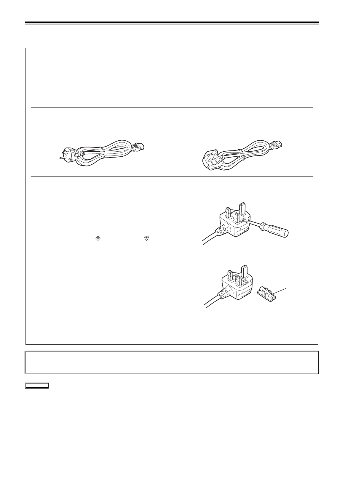
This product is equipped with 2 types of AC mains cable. One is for continental Europe, etc. and the other one is only
for U.K.
Appropriate mains cable must be used in each local area, since the other type of mains cable is not suitable.
FOR CONTINENTAL EUROPE, ETC.
Not to be used in the U.K.
FOR U.K. ONLY
This appliance is supplied with a moulded three pin mains
plug for your safety and convenience.
A 13 amp fuse is fitted in this plug.
Should the fuse need to be replaced please ensure that the
replacement fuse has a rating of 13 amps and that it is approved by ASTA or BSI to BS1362.
Check for the ASTA mark or the BSI mark on the
body of the fuse.
If the plug contains a removable fuse cover you must ensure that it is refitted when the fuse is replaced.
If you lose the fuse cover the plug must not be used until a
replacement cover is obtained.
A replacement fuse cover can be purchased from your local Panasonic Dealer.
FOR U.K. ONLY
If the plug supplied is not suitable for your socket outlet, it should be cut off and appropriate one fitted.
How to replace the fuse
1. Open the fuse compartment with a screwdriver.
2. Replace the fuse.
Fuse
IF THE FITTED MOULDED PLUG IS UNSUITABLE FOR
THE SOCKET OUTLET IN YOUR HOME THEN THE
FUSE SHOULD BE REMOVED AND THE PLUG CUT
OFF AND DISPOSED OF SAFELY. THERE IS A DANGER OF SEVERE ELECTRICAL SHOCK IF THE CUT
OFF PLUG IS INSERTED INTO ANY 13 AMP SOCKET.
DO NOT REMOVE PANEL COVERS BY UNSCREWING THEM.
To reduce the risk of electric shock, do not remove the covers. No user serviceable parts inside.
Refer servicing to qualified service personnel.
indicates safety information.
4
Page 5

Contents
Read this first! ...........................................2
Introduction................................................6
Features......................................................6
Parts and their functions ..........................9
Front panel (1) ......................................................9
Front panel (2) ....................................................10
Front panel (3) ....................................................11
Display panel ......................................................12
Rear panel ..........................................................14
Reference signals....................................16
Reference frequencies............................17
Tapes ........................................................18
Connections.............................................19
Example of connections
with an editing controller .....................................19
IEEE1394 digital interface.......................20
Settings for this unit ............................................20
Precautions for use .............................................20
VANC data recording/playback..............21
VANC data recording ..........................................21
VANC data playback ...........................................21
Joystick and
Variable Speed Playback ........................22
Joystick ...............................................................22
Variable Speed Playback....................................22
PF (Programmable Function) ................. 23
Performing operations using the PF buttons.......23
Operation using the PF buttons ..........................23
Pause/Recording
(Recording with pauses).........................24
Cue up ......................................................24
Repeat playback ......................................25
Setting the BEGIN and END points ....................25
Setting the repeat playback mode ......................25
Recording from a variable frame rate
camera......................................................26
Recording the HD SDI output signal
from a variable frame rate camera......................26
Field displacement ..............................................26
Setup (initial settings).............................27
Setting method using the on-screen menus .......27
Returning to the factory settings .........................27
Setting the user defaults .....................................28
User default loading method...............................29
Menu protection method .....................................30
Menu protection release method ........................30
System frequency switching ...............................31
Procedure for shifting the system frequency.......31
Setup menus............................................32
Menus which are displayed ................................32
SYSTEM............................................................. 36
BASIC................................................................. 37
Formats for playback ..........................................39
OPERATION ......................................................40
INTERFACE ....................................................... 43
EDIT ................................................................... 44
TAPE PROTECT ................................................45
TIME CODE........................................................45
VIDEO ................................................................47
AUDIO ................................................................51
DIF...................................................................... 53
MENU .................................................................54
Time code/user bits.................................55
Timecodes recorded by this product .................. 56
Superimpose screen ...............................57
Video head cleaning................................58
Condensation...........................................58
Maintenance.............................................58
Error messages .......................................59
DIAG menu......................................................... 59
Displaying the DIAG menu .................................59
Displaying the “HOURS METER” information ....59
UMID information display ...................................60
Displaying the warning information.....................61
Error messages ..................................................62
Emergency eject......................................64
Specifications ..........................................65
5
Page 6

Introduction
This unit is a multi-format VTR capable of recording and
playing back HD signals (1080i/59.94 Hz, 1080i/50 Hz,
720P/59.94 Hz, 720P/50 Hz) in DVCPRO HD-LP format
using a small cassette tape 1/4 inch wide, HD (DVCPRO
HD/DVCPRO HD-LP*) and SD (DVCPRO50/DVCPRO)
recorded in DVCPRO format as well as conventional
consumer DV/DVCAM tapes.
A down-converter as a standard feature verifies all tapes
using analog composite signals and SD SDI output.
Similarly, each of the following output signals can be
obtained.
Features
Compact size and light weight
The unit has a width of 214 mm (8-7/16 inches), a height
of 132 mm (5-1/4 inches), and a depth of 442 mm (17-3/
8 inches) (Protruding portion is not included), and
weighs only 8.5 kg (18.74 lb).
Grips are also attached for easy carry.
Efficient installation in a rack
The unit’s width is one-half of 19 inches and its height is
3U: this translates into greater saving of installation
space in a standard rack compared to conventional
models.
DVCPRO HD cassette tapes used
The unit uses 1/4-inch wide cassette tapes.
<Note>
When recording HD signals, use DVCPRO HD
cassettes.
High image quality
The unit achieves a high image quality by recording
4:2:2 HD component signals with a recording rate (=100
Mbps) which is four times as high as that for existing
DVCPRO formats.
z 720/25p over 60p sources can be converted to 1080/25
PsF or 576i format output signals.
z 720/50p over 60p sources can be converted to 720/50p,
1080/50i or 576i format output signals.
The compact size and light weight of the unit enable it to be
carried around and mounted in a standard rack with ease.
You can perform the unit’s settings interactively with the onscreen menus displayed on the TV monitor.
* DVCPRO HD-LP has the same format as the DVCPRO HD EX
described in the operation manual of our camera recorder.
Frame rate conversion
When playing back a tape recorded at a frame rate of 24
fps using a variable frame rate camera, the tape’s
signals can be converted to the 1080/24 PsF format and
output by selecting a menu item setting.
When playing back a tape recorded at a frame rate of 25
fps, the tape’s signals can be converted to the 1080/25
PsF or 576i format and output. When playing back a
tape recorded at a frame rate of 50 fps, the tape signals
can be converted to the 1080/50i or 576i format and
output.
<Notes>
z Use tapes that are shot with a variable frame rate
camera.
z Do not use dubbed or edited tapes. The tape control
information may be lost, making it impossible to
convert the signals for playback.
DVCPRO-compatible playback
In addition to DVCPRO HD-LP playback, the unit can
play back tapes recorded using the existing DVCPRO
HD, DVCPRO50 and DVCPRO formats.
It can also play back consumer DV tapes (SP) and
DVCAM tapes.
1080i or 720p, NTSC or PAL selectable
By switching the settings provided for the video signal
input (1080i/59.94 Hz or 720p/59.94 Hz) on the setup
menu, the unit can record and playback each signal and
also playback NTSC SD material.
The unit also supports the PAL mode. Playback of
1080i/50 Hz, record and playback of 720P/50 Hz or
playback of PAL SD materials is enabled by switching
the setting on the system menu.
6
SD down-converter
The unit comes with a built-in SD down-converter as a
standard feature to enable the output of SD SDI signals
and analog composite signals at the same time as HD
SDI output signals and for monitoring the signals on an
SD monitor.
Up-convert function
When an SD format tape is played back, it is possible to
output the signals in the HD SDI output and HD analog
component signals while at the same time outputting
them in SD format, since this unit includes the HD
converter as a standard feature.
Page 7

Features (continued)
Cross-convert function
The unit comes with a built-in cross-converter to enable
1080i/59.94 Hz format signals to be converted into
720p/59.94 Hz format signals or, conversely, to enable
720p/59.94 Hz format signals to be converted into
1080i/59.94 Hz format signals.
Cross-convert with 1080i/50 Hz and 720p/50 Hz is also
possible.
HD analog component output
This feature enables HD signals to be monitored with
ease.
Gamma correction of cinema for film
This feature corrects the image from a variable frame
rate camera in cinema gamma mode for film to an image
with film quality.
AC/DC operation
The unit supports AC supply voltages ranging from
100V to 240V and DC12V power supply as well.
Editing function
Using the 9-pin serial remote (RS-422A), assembly or
insertion is allowed.
(Only with 1080i/59.94 Hz, 720P/59.94 Hz, 1080i/50 Hz,
and 720P/50 Hz)
Encoder remote controller function
Using the external encoder remote controller, each
setting for the video output signal can be adjusted.
PF (Programmable Function) button
The unit is equipped with three PF buttons. Selecting
the three most frequently used setup menus, the menu
settings can be changed with the buttons on the front
panel.
UMID information recording and playback
This unit supports the recording/playback of UMID
(Unique Material Identifier) information in the SMPTE
330M standard. UMID information can be confirmed
with the diagnostic menu.
VTRs that do not support the recording/playback of
UMID information will not playback UMID information
correctly. In addition, when VTRs that do not support
recording/playback of UMID information are connected
to this unit, UMID information will not be recorded
correctly.
VANC data recording/playback
VANC data packets that added to the Y stream of HD
SDI can be recorded with the video signal. In addition,
VANC data packets can be played back with the Y
stream of HD SDI. This unit is capable of input and
output through the IEEE1394 standard interface.
AUTO REC Feature
This unit can be connected to our camera recorder
using HD SDI signals. It is possible to remotely turn ON/
OFF the recording feature of this unit by using
overlapped commands.
Follow-on recording function
Using the REC button and PAUSE button together
activates the auto back function, enabling the next
image to follow on from the last image with no
disruptions in the continuity.
On-screen menu settings
Highly detailed and individualized function settings can
be performed on-screen.
Time code
The unit is equipped with a built-in time code generator/
time code reader (TCG/TCR). Since time code signals
can also be input from an external device, regeneration
to an external time code is possible.
Since the backup function using a backup battery is
incorporated in the TCG (time code generator), time
codes during free-run operations are retained even if the
power of the unit is turned off.
Joystick and variable speed playback
The unit is equipped with a joystick (stick controller) for
use of the search function during variable speed
playback.
In addition, the joystick allows convenient setting of the
onscreen menu/time code generator.
7
Page 8

Features (continued)
Multi-functional interfaces
z Serial digital input/output
The unit’s HD component serial I/O interface enables
interfacing with HD component video signals and 8channel digital audio signals using a single BNC
connector. (SMPTE 292M/296M/299M)
The unit is also equipped with an SD downconverter as
a standard feature so that SD component serial signals
can be output as well.
(SMPTE 259M-C, 272M-A, ITU-R BT.656-4)
z Analog video output
Since the unit’s down-converter comes as a standard
feature, the analog composite signals can be monitored
on an SD monitor.
z 9-pin remote
The unit’s 9-pin remote control connector enables it to
be operated with an external remote controller.
z IEEE1394 digital input/output
Set to this position when controlling this unit with the AV/
C command of the 9-pin REMOTE, REMOTE of HD
SDI, IEEE1394.
<Playback formats and output formats>
Playback format Output format
DVCPRO HD-LP,
DVCPRO HD
DVCPRO50 DVCPRO50, DV
DVCPRO DVCPRO, DV
DV, DVCAM DV
In case of EE and REC modes:
z Select a value other than “1394” with the
INPUT SELECT button on the front
panel.
DVCPRO HD,
DVCPRO50, DV
DVCPRO HD
<Note>
When any of the settings below is established, no
signals will be output from the IEEE1394 digital
interface.
z When “60/24” is selected as the menu item No.030
HD FREQUENCY setting
z When “23/24,” “25 (HD),” “25 (SD),” “50 (HD),” or “50
(SD)” is selected in menu item No. 025 SYSTEM
FREQ.
8
Page 9
Parts and their functions
Front panel (1)
HD
REC
CH3/7 CH4/8
PB
PB
REC/PB
CH1 CH2 CH1 CH2
CH1/5 CH2/6
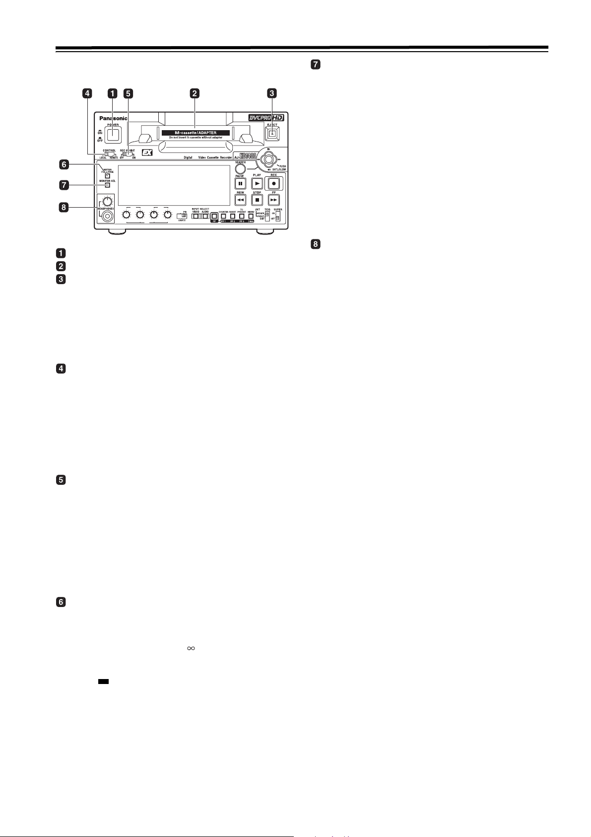
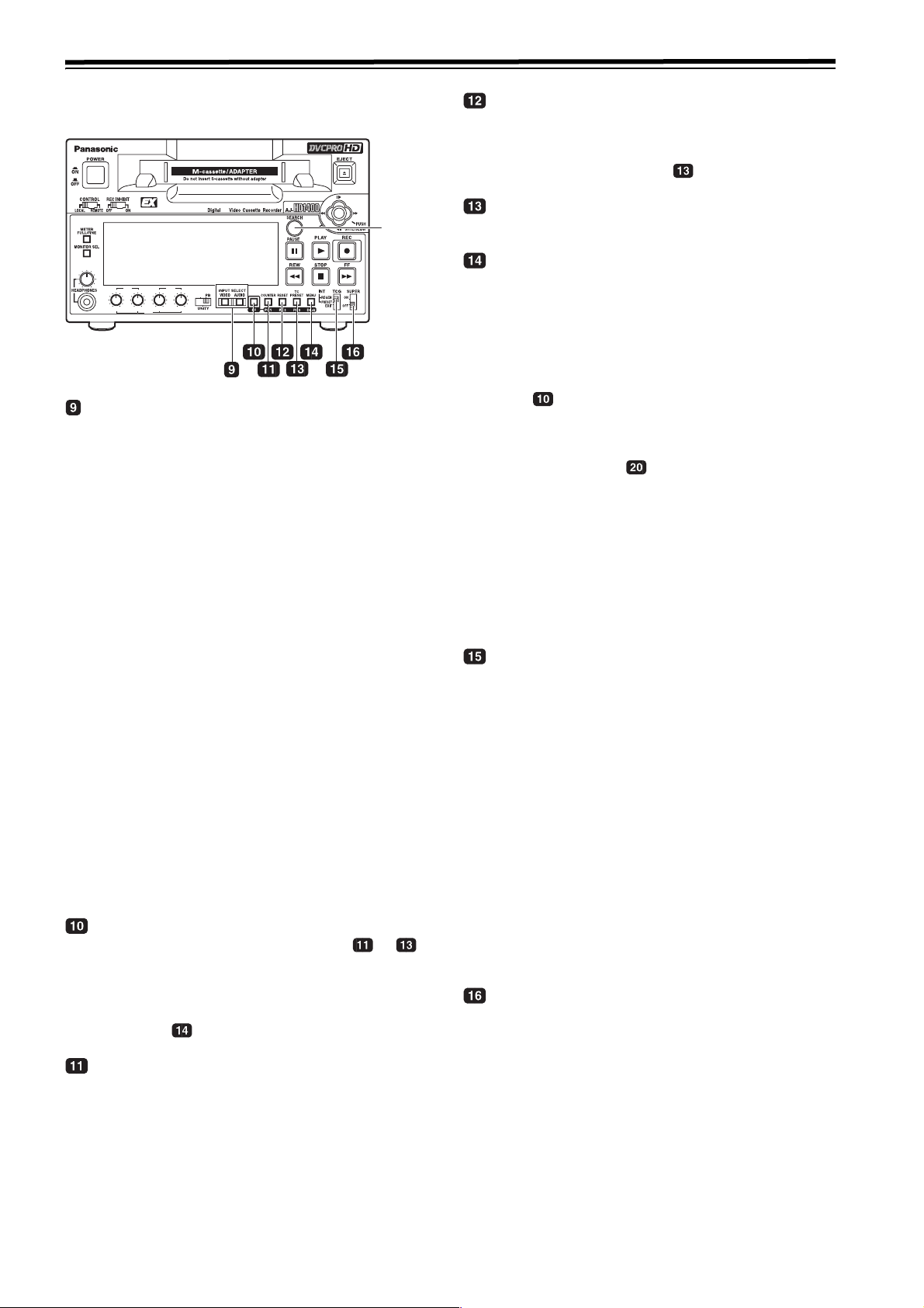
POWER switch
Cassette insertion slot (See page 18)
EJECT button
When this button is pressed, the tape is unloaded and
the cassette is ejected automatically a few seconds
later. When CTL display has been selected for the
counter display, the display is reset.
To enable or disable the EJECT button operation during
recording, use menu No. 115 EJECT SW INH.
CONTROL switch
This is selected to control the unit from an external
source using the REMOTE connector.
REMOTE: Set to this position when controlling the unit
with the AV/C command or the commands
overlapped on the HD SDI of the 9-pin
REMOTE, via IEEE1394.
LOCAL : Set to this position to control the unit using
the controls on the unit’s operation panel.
MONITOR SEL button
This button is used to select the audio signals which are
to be output to the AUDIO MON L and R connectors.
Each time the button is pressed, the audio signals to be
output to the AUDIO MON L or R connector are
changed in the following sequence.
[CH1] [CH3] [CH1] [CH2] [CH3] [CH4]
L :
R :
[CH2] [CH4] [CH1] [CH2] [CH3] [CH4]
[CUE] [CH1+CH2] [CH3+CH4]
[CUE] [CH1+CH2] [CH3+CH4]
Which signal is currently selected is displayed by the
lighting of the L or R lamp on the level meter display.
Select [CH5-8] on the menu No. 783 AUDIO CH SEL to
monitor CH5 to CH8.
Headphone jack and volume control
When stereo headphones are connected to the headset
jack, you can monitor the audio signal through the
headphones during recording and playback.
The headphone volume for output and monitoring output
can be adjusted with the volume control knob. Whether
the monitoring volume is linked to the volume control
knob or not can be selected in menu No. 712 MONI
OUT. In independent operation, the monitor output is
fixed regardless of the position of the volume control
knob.
Also, the output volume of the headphones is always
linked to the volume control knob.
REC INHIBIT switch
This switch is used to enable or disable recording on the
cassette tape.
ON: Recording on the cassette tape is disabled
(inhibited). In this state, the REC INH lamp lights
on the display panel.
OFF: Recording on the cassette tape is enabled so
long as the accidental erasure prevention
mechanism on the cassette tape is set to enable
recording.
METER (FULL/FINE) selector button
This button is used to select the scale display for the
audio level meter.
FULL mode:
The standard scale (– to 0 dB) is selected.
FINE mode:
The scale in 0.5 dB increments is selected. The
position indicates the standard level of –20 dB
(For AJ-HD1400P) or –18 dB (For AJ-HD1400E).
(See page 12)
9
Page 10
Parts and their functions (continued)
Front panel (2)
HD
REC
CH1 CH2 CH1 CH2
CH1/5 CH2/6
INPUT SELECT buttons
These buttons are used to switch the video and audio
input signals. They can also be used to switch the video
input signals to the internal reference signal selected as
the menu item No.601 VIDEO INT SG setting.
VIDEO:
When SG has been selected, the signal is switched to
the internal reference signal selected as the menu item
No.601 VIDEO INT SG setting.
AUDIO:
<Notes>
z It is possible to inhibit the input switch operations
(video and audio) of the INPUT SELECT buttons
using menu item No.190 V IN SEL INH and item
No.191 A IN SEL INH.
z The audio input signal cannot be switched to [1394]
independently. The audio signal can be switched to
[1394] only when the video signal is switched to
[1394] by interlocking.
Since the audio input signal at this time is fixed to
[1394], it cannot be switched to another input signal.
PF button
When this button is pressed, buttons - to
function as the PF1, PF2 and PF3 buttons, respectively.
When it is pressed again before another button is
pressed, these modes are canceled.
When this button is pressed together with the MENU/
DIAG button , the DIAG screen is displayed.
COUNTER/PF1 button
Each time this button is pressed, the counter display on
the display panel changes by one step in the following
sequence: CTL > TC > UB > REM.
PB
REC/PB
CH3/7 CH4/8
PB
Each time the VIDEO button is pressed, the input
video signal selection is switched in the order of
[HD SDI] > [1394] > [SG].
Each time the AUDIO button is pressed, the input
audio signal selection is switched in the order of
[HD SDI] > [SG] > [ANALOG].
SEARCH
button
RESET/PF2 button
When this button is pressed in the CTL mode, the
counter display is reset to [00:00:00:00].
When it is pressed in the TC/UB mode while holding
down the TC PRESET button , the generator is reset.
TC PRESET/PF3 button
This button is used to set the TC or UB values.
MENU/DIAG button
When the connector that is selected in menu No. 005
SUPER is used, When this button is pressed, the setup
menus are displayed on the TV monitor, and the setup
menu numbers are displayed on the unit’s display panel.
When it is pressed again, the setup menu settings are
exited, and the original status is restored.
When the button is pressed while holding down the PF
button , the VTR information is displayed. When it is
pressed again, the original display is restored. The VTR
information consists of the WARNING, HOURS METER,
UMID INFO and DIF STATUS 1, 2 information.
The SEARCH button is used to switch the displays
between these kinds of information.
Descriptions of the warnings are displayed on the
WARNING screen. The deck’s serial number, poweron
time, drum rotation time, tape travel time, number of
loading times, number of power on/off times, etc. are
displayed on the HOURS METER screen. The UMID
(Unique Material Identifier) information is displayed on
the UMID INFO screen. The IEEE1394 digital interface
information is displayed on the DIF STATUS 1, 2 screen.
TCG switch
REGEN
: The internal time code generator is
synchronized with the time code which the time
code reader has read from the tape.
The signal that is to be used for regeneration is
selected using menu No. 505 TCG REGEN.
PRESET
: The time code generator can be preset (see
page 55) on the operation panel or by remote
control.
EXT: The external time code which is input from the
time code input connector or video signal SLTC,
SVITC or IEEE1394 digital input signal is used.
Which of the two is to be set is selected using
menu No. 507 EXT TC SEL.
<Note>
When selecting “1394” with the INPUT VIDEO switch on
the front panel, the time code input to IEEE1394 digital
input/output connector is used.
SUPER switch
ON: Outputs superimposed information, such as time
code, to the connector selected in menu No. 005
SUPER.
OFF: No superimposed information is output.
10
Page 11
Parts and their functions (continued)
Front panel (3)
HD
REC
CH3/7 CH4/8
PB
PB
REC/PB
CH1 CH2 CH1 CH2
CH1/5 CH2/6
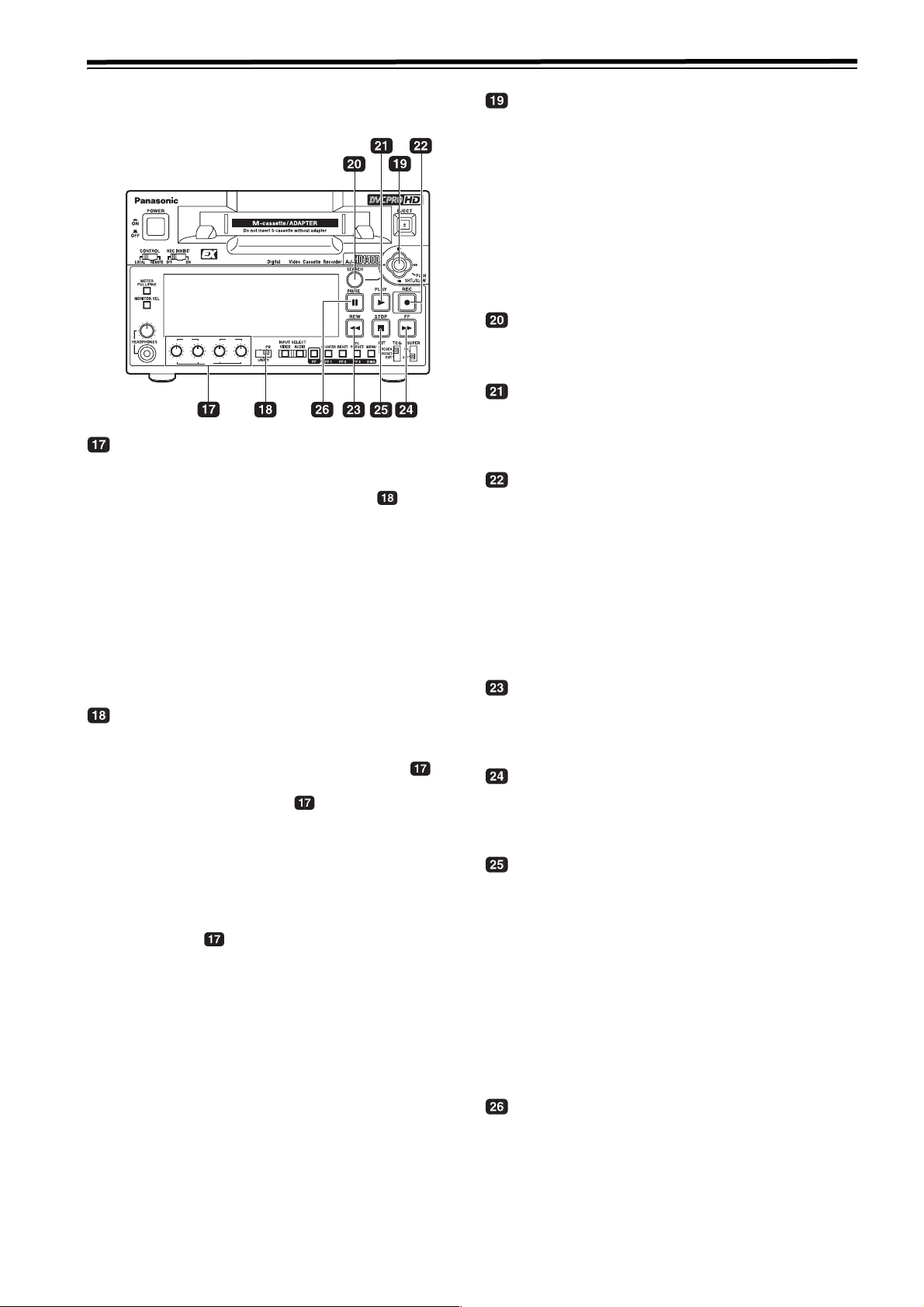
Audio level control knobs
These knobs are used to adjust the recording and
playback level of the PCM audio signals.
The audio level control selector switch switches
between the recording/playback level adjustment for
CH1/CH2 and the playback level adjustment for CH1 to
CH4.
<Notes>
z The level of the IEEE1394 digital input/output audio
signals cannot be adjusted.
z For the recording level, only the analog input can be
adjusted.
z For HD SDI and SG, only the playback level is
adjustable.
Audio level control selector switch
UNITY: At this position, the audio signals are recorded
or played back at a fixed level regardless of the
position of the audio level control knobs .
REC/PB
: The two switches on the left side of the audio
level control knobs control the recording
level for the audio signal from analog input CH1/
CH2, and the two switches on the right side
control the playback level for the audio signal for
CH1/CH2.
PB: At this position, the audio signals for CH1 - CH4
or CH5 - CH8 are played back at the level which
has been adjusted by the audio level control
knobs .
<Note>
When selecting PB, the recording level is UNITY.
Selecting CH1 to CH4 makes the playback level of CH5
to CH8 UNITY while selecting CH5 to CH8 makes the
playback level of CH1 to CH4 UNITY.
Selecting between CH1 to CH4 and CH5 to CH8 can be
performed using menu No. 783 AUDIO CH SEL.
Joystick
This is used for shuttle, slow and other variable-speed
playback. It is also used for the menu settings, etc.
The stick can be moved upward, downward, to the left or
to the right, and it can also be pressed to initiate
operations. (See “Joystick and Variable Speed
Playback” (page 22))
<Note>
When this unit is turnning on, do not use the stick.
Variable-speed playback and menu setting operation
become impossible.
SEARCH button
When this button is pressed, the search mode is
established.
PLAY button
When this button is pressed, playback starts.
When this button and the REC button are pressed
together, recording starts.
REC button
When this button is pressed together with the PLAY
button, recording starts.
When it is pressed during playback, a search, fast
forwarding or rewinding, the EE mode pictures and
audio signals can be monitored while it is held down.
When it is pressed in the stop mode, the EE mode
pictures and audio signals can be monitored. (When it is
pressed during playback, the servo will be disrupted.)
When the STOP button is pressed, the original pictures
and sound are restored.
REW button
When this button is pressed, the tape is rewound. The
rewinding speed can be selected using menu No.102
FF. REW MAX.
FF button
When this button is pressed, the tape is fast forwarded.
The fast forwarding speed can be selected using menu
No.102 FF. REW MAX.
STOP button
When this button is pressed, the tape stops traveling,
and when “TAPE” has been selected for the menu item
No.140 OUTPUT setting, the still images can be
monitored.
Even in the stop mode, the drum continues to rotate,
and the tape remains in close contact with the drum.
When the stop mode continues beyond a specific time
period, the unit is automatically set to the standby OFF
mode or STEP FWD mode in order to protect the tape.
(This is set using menu item No.400 to 403.)
Immediately after a cassette has been loaded in the
unit, the stop mode is established.
PAU S E b utton
When this button is pressed during recording, the
recording operation stops temporarily. Restart the
recording by pressing the button again.
When this button is pressed during playback, the screen
changes to a static display. Restart playback by pressing
the button again.
11
Page 12

Parts and their functions (continued)
Display panel
!2"
REMOTE
dB
4
3
2
1
0
-1
-2
-3
-4
CH-15
LR
!3"
dB
0
-12
-20
26
L
R
!4"
dB
4
3
2
1
0
-1
-2
-3
-4
CH-37
L
!5"
!6"
U
WIDE
dB
0
-12
-20
48
R
L
R
!1"
!7"
COMP
GAMMA
dB
-12
-20
CUE
L
R
!12"
!8"
SYSTEM
59.94 60
50/25PsF
23.98
25
HD
CTL
TC
UB
REM
24
50
SD
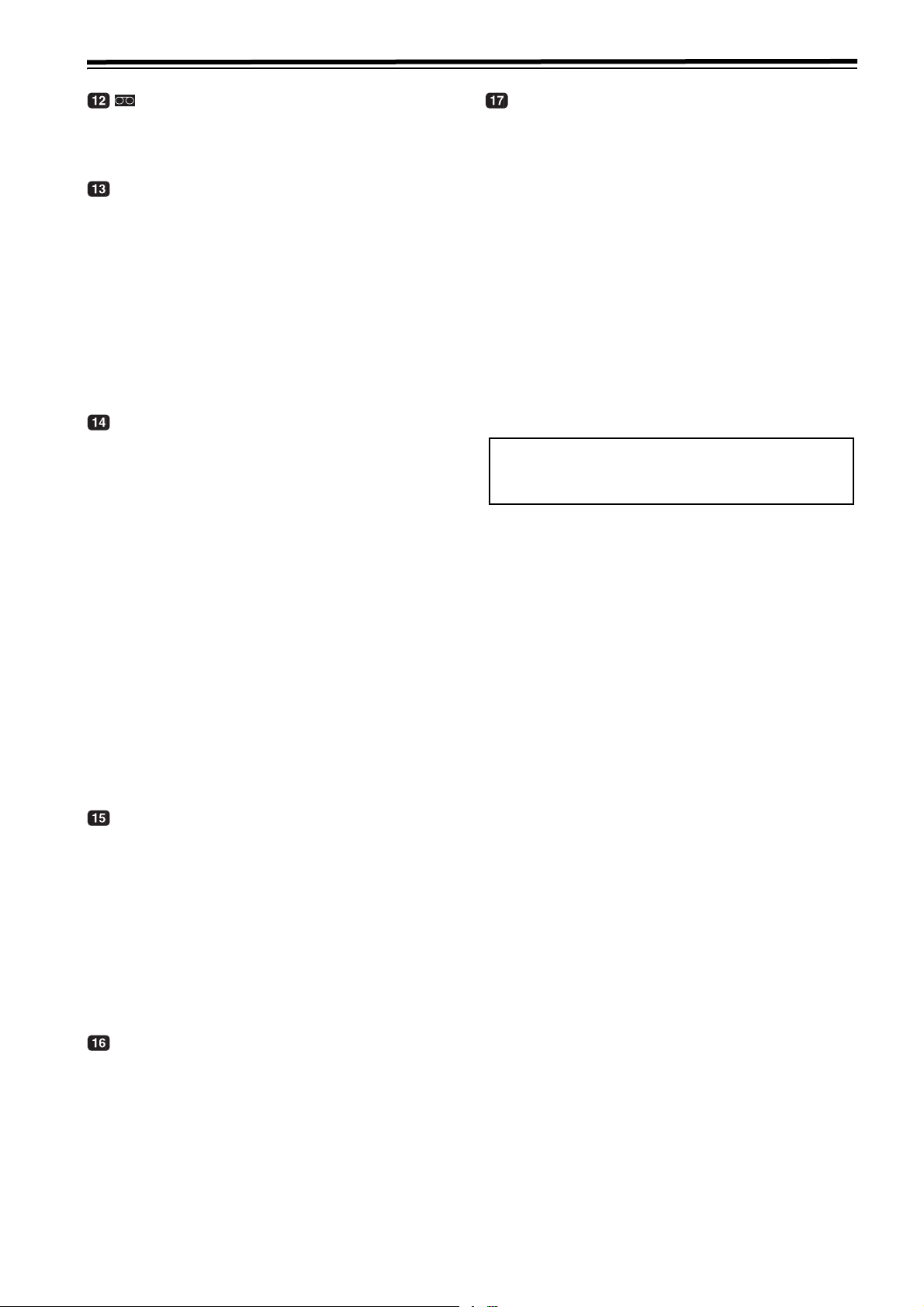
Level meter
Displays CH1/CH2/CH3/CH4 of the PCM audio signal or
each level of CH5/CH6/CH7/CH8 and the CUE track.
During recording and when the EE mode is selected, it
shows the levels of the input audio signals; during
playback, it shows the levels of the output audio signals.
The audio level display is switched to CH1/CH2/CH3/
CH4 and CH5/CH6/CH7/CH8 by selecting menu No.
783 AUDIO CH SEL. (See page 52)
The audio level display is switched between the FULL
mode and FINE mode using the METER selector button
(See page 9).
Reference level
(–20dB: AJ-HD1400P)
Reference level
(–18dB: AJ-HD1400E)
!9"
DVCP RO
DVCP RO
DVCP RO
DV CAM
V F R
AUTO REC
DV CONTROL
!10"
HD
HD
50
!17"
1080i
720p
EDIT REC
VIDEO
HDSDI
1394 SG
!11"
INH S
AUDI O
HDSDI
1394 SG
ANALOG
!16"
!14"
!15"
!13"
COMP lamp
This lamp turns on when “DARK” is selected in menu
No. 693 COMP MODE.
SYSTEM FREQ display screen
Displays the selections of menu No. 25 SYSTEM FREQ.
VFR (Variable Frame Rate) lamp
This lamp lights when a tape (24/25/50PsF) from a
variable frame rate camera is played back after selecting
the frame rate converter and when conversion is
performed normally.
If the tape and selected frame rate conversion function
for play back do not match, the lamp flashes on and off.
Select the frame rate conversion function in menu No.
25 SYSTEM FREQ. (See page 37)
FULL mode FINE mode
FULL mode
FINE mode
REMOTE lamp
This lamp lights when the CONTROL switch has been
set to the REMOTE position.
Repeat lamp
This lights when the repeat play mode has been set.
U lamp
This lamp lights when UMID information is present on
the input signal in EE mode.
This lamp lights during tape playback when UMID
information has been recorded on the tape.
WIDE lamp
This lamp turns on when “SQUEEZ” is selected in menu
No. 620 DOWNCON MODE and the down-conversion
output is set to wide screen, or when wide screen
information is recorded on tape when an SD tape is
played back.
Format displays
The recording format and the format (DVCPRO HD
1080i/DVCPRO HD 720P/DVCPRO 50/DVCPRO/DV/
DVCAM) of the tape inserted in the unit are displayed
here.
INPUT SELECT display area
The characters corresponding to the selected input
signals light up in this area. With the exception of analog
audio signals, flashing appears in this area if the
selected input signals are not available.
VIDEO
HDSDI
: HD serial digital video signals
1394: IEEE1394 digital signals
SG: Internal reference signal
AUDIO
HDSDI
: HD serial digital audio signals
1394: IEEE1394 digital signals
SG: Internal reference signal
ANALOG
: Analog audio signals
GAMMA lamp
This lamp lights when GAMMA function is selected in
menu No.693 GAMMA SEL.
12
Page 13
Parts and their functions (continued)
lamp
This lamp lights when a cassette tape is inserted into
the VTR.
In the standby OFF mode, this lamp is flashing.
Counter display
The tape counter, time code, etc. are displayed here.
The type of value displayed is indicated by CTL, TC, UB
or REM.
CTL: This area indicates the tape timer (control signal).
TC: This area indicates time code data.
UB: This area indicates user bit data.
REM: This area indicates the remaining tape time and
total tape duration in minutes.
Example: [30-46]
Remaining tape time: 30 minutes,
Total tape duration: 46 minutes
EDIT/EDIT REC/REC/REC INH lamps
EDIT: This lamp lights when the edit mode is selected.
(9-pin control)
EDIT REC:
This lamp lights when in the editing record status.
(9-pin control)
REC: This lights in the recording mode.
REC INH:
This lamp lights in the recording prohibited status
(when the front upper REC INHIBIT switch is
“ON” or when the tape was recorded in a format
other than DVCPRO HD-LP and was played back
while “ON” was selected in menu No. 118 SP
MODE INH, or the cassette is in the erase
protection status.)
Recording is not possible while this lamp is
lighted.
Whether the lamp is to light or flash when the
accidental erasure prevention tab on the cassette
tape has been set to the recording inhibit position
can be selected using menu item No.114 REC
INH LAMP.
Backup battery warning lamp
This lamp displays the voltage condition of the backup
battery for 5 seconds after turning on the power.
Steady light
Flashing : The backup battery is not installed
This unit is equipped with a backup mechanism to count
down the time code generator while the power of the
unit is turned off. For details, refer to “Time code when
power is not supplied” (page 56).
The battery must be replaced periodically, since this unit
cannot count down and the numerical value of the time
code generator is reset if the backup battery voltage
drops below the specified value. However, it is not
necessary to replace the battery when it is not
necessary to drive the backup feature.
: The voltage is the specified voltage or
more
properly or the voltage of the backup
battery is less than the specified voltage.
<NOTE>
Refer replacement of backup battery to qualified
service personel.
Channel condition lamps
These lamps light to indicate the error rate status.
Green
: This lights when the error rates for the video and
audio playback signals are both at acceptable
levels.
White
: This lights when the error rate for the video or
audio playback level has increased.
The playback picture and sound remain
unaffected even while this lamp is lighted.
Red: This lights when the error rate for the video or
audio playback level has increased to the extent
that correction or interpolation was performed.
S (servo) lamp
This lights when both the drum servo and capstan servo
are locked.
13
Page 14
Parts and their functions (continued)
Rear panel
TC
AUDIO OUT
CH1
MONITOR
IN
OUT
CH2
PUSH
PUSH
R
HD/SDI
IN
OUT1
OUT2
SD/SDI
DVCP RO
/DV
PUSH
PUSH
L
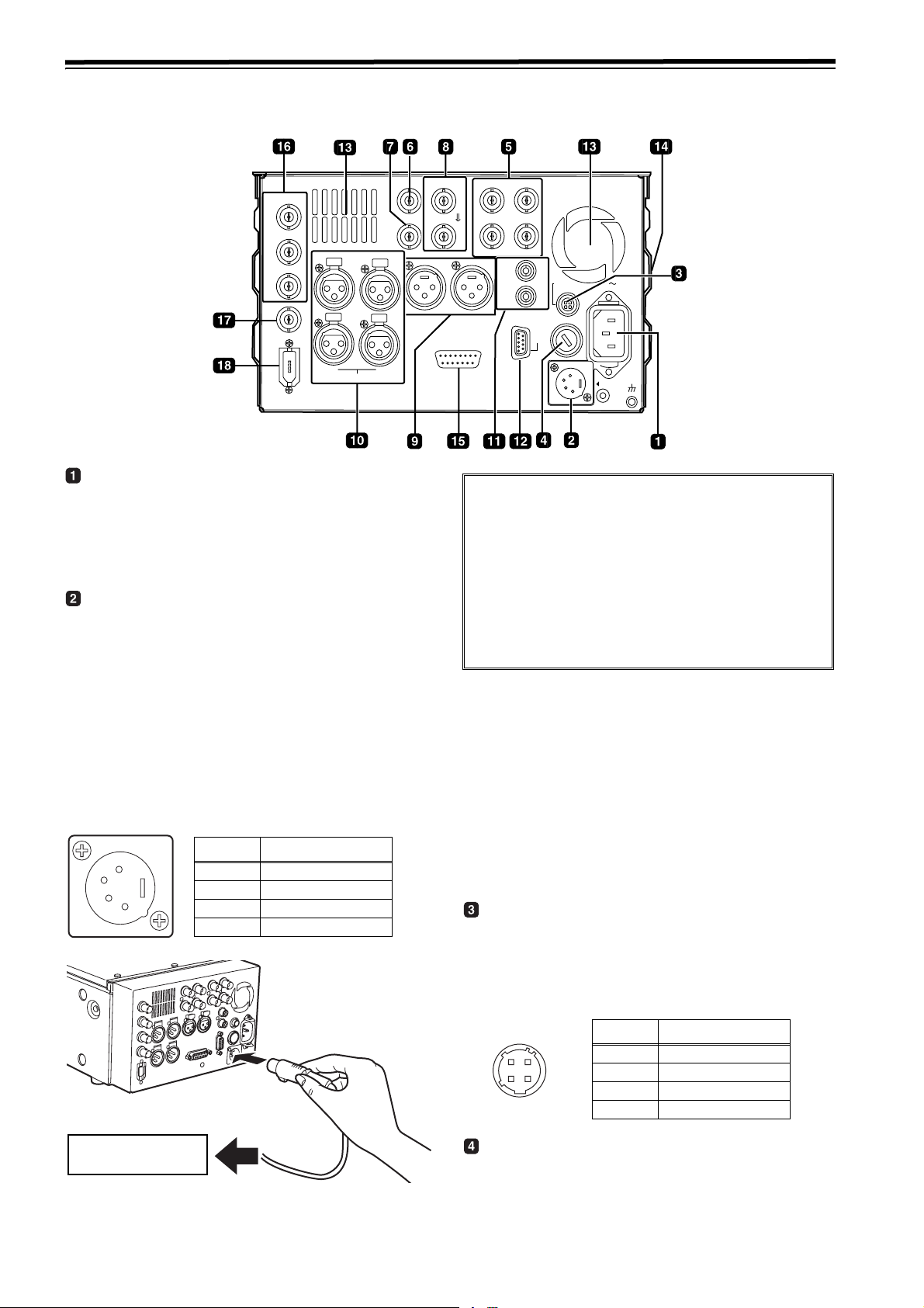
AC IN inlet
This is the AC power inlet.
Connect the accessory power cable here.
When both an AC power supply and DC power supply
have been connected, the AC power supply takes
priority.
DC IN socket
This is the input connector for the DC 12V supply
voltage.
Use an external DC power supply rated at DC 12 V/7 A
(12 A peak or higher)
When the voltage has dropped to around 10.6V, the
unit’s power is automatically turned off. (When “TYPE-A”
or “TYPE-B” is not selected as the menu item No.180
BATTERY SEL setting)
Even when the supply voltage is restored later, the
power will not automatically come back on. The POWER
switch must be set to OFF and then back to ON several
seconds later.
Pin No. Signal
1
2
3
4
1 Ground
2–
3–
4 +12 V
ENCODER
REMOTE
1
2
(SUPER)
CH2
VIDEO OUT
Y
AUDIO
MON
OUT
P
B
P
R
L
DC OUT
12V 250mA
R
R
E
FUSE 250V T2.5AH
M
F1
O
R
T
DC IN
AC IN
SIGNAL
GND
HD/SD REF IN
AUDIO IN
CH1
If an external DC power supply is used, then check the
ratings of the external DC power supply so that they are
compatible with those of this unit. Check the pin
arrangements of the DC output terminal of the external DC
power supply and those of the DC IN socket of this unit so
that their polarities are correctly arranged.
If +12 V are supplied to the unit’s GND terminal by
mistake, this may cause fire or injury.
If the polarities of the DC IN connectors of other devices
are incorrect, and the other devices are connected to the
unit by mistake, fire or personal injury may result.
<Notes>
z If an external DC power supply is used, then make
sure that the external DC power supply is first turned
ON, then this unit is turned ON. Improper operation
may result in a malfunction in the unit due to slow
startup of the output voltage of the external DC power
supply.
z If input exceeds 18 V by mistake, the protection
feature shuts down the power source at around 20 to
35 V. Change the voltage to the regular voltage, and
the unit is available. An AC source cannot be
connected to this terminal.
DC OUT socket
This is the DC 12V output socket.
Power is supplied from here to the external remote
controller (AJ-A95: optional accessory).
The DC power cable is packed together with the AJA95.
External DC adapter
14
Pin No. Signal
2
3
4
1
1 Ground
2–
3–
4 +12 V
Fuse holder
This holds the AC 250 V/2.5 A fuse (time lag type).
<Note>
Use the fuse specified by Panasonic.
Page 15
Parts and their functions (continued)
VIDEO OUT (1, 2, Y, PB, PR) connectors
By changing the menu item No.615 V OUT SEL setting,
either analog composite signals or HD analog
component Y signals are output from the VIDEO OUT1
connector.
Analog composite signals with superimposed information
embedded can be output from the VIDEO OUT2 connector.
Whether superimposed information is to be embedded
in the signals is selected using menu item No.005
SUPER.
<Note>
When HD analog component output or HD SDI output
signals are output with the 60 Hz or 24 Hz system
frequency, the SD SDI signals will be output without the
sync signals (NO SYNC), and the analog composite
signals will be output in the black-and-white mode (burst
OFF).
TC IN connector
This is used to record an external time code onto the
tape.
TC OUT connector
This is used to output the playback time code during
playback.
During recording, the time code generated by the
internal time code generator is output from this
connector.
HD/SD REF VIDEO IN connector and OUT
connector
Input connector for the HD/SD reference video signal
and loop through output connector.
<Notes>
z When inputting an HD reference signal to the
connector, input a tri-level sync signal with positive
and negative polarities. Also, supply signals matching
the input signals and tape format.
z When inputting an SD reference signal to the
connector, use a black burst signal which satisfy the
SMPTE170M or ITU624-4 standard.
z If no cable is connected to the REF VIDEO OUT
connector, the REF VIDEO IN connector will be 75
h
automatically. If the cable is connected, the 75 h
connection is cancelled.
AUDIO IN connectors (CH1, CH2)
These are the input connectors for the analog audio
signals.
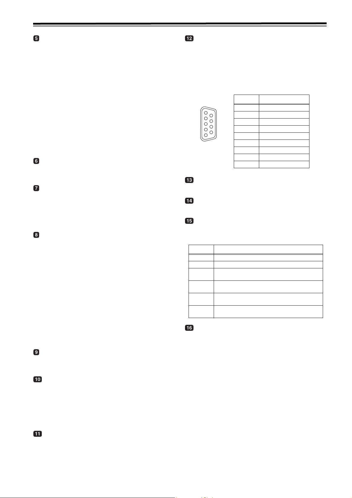
REMOTE CONTROL connector
An external remote controller is connected here to
enable the unit to be operated using an external device.
<Notes>
z Set the LOCAL/REMOTE switch to REMOTE.
z The connector satisfies the RS-422A interface
standard.
Pin No. Signal
1
6
9
5
1 Frame Ground
2 Transmit A
3 Receive B
4 Receive Common
5–
6 Transmit Common
7 Transmit B
8 Receive A
9 Frame Ground
Fan motor
This is provided to cool off the unit.
Grips
This is the handle for carrying the unit.
ENCODER REMOTE connector
Connect a connector encoder remote controller when
externally adjusting each setting of the video output signal.
Pin No. Signal
1 FRAME GROUND
4 REM(G)
REM RX (X)
7
REMOTE CONTROL PROTOCOL RECEIVE
REM TX (X)
8
REMOTE CONTROL PROTOCOL TRANSMIT
REM RX (Y)
14
REMOTE CONTROL PROTOCOL RECEIVE
REM TX (Y)
15
REMOTE CONTROL PROTOCOL TRANSMIT
HD SERIAL COMPONENT AUDIO VIDEO IN/
OUT connector
These are input-output connectors for the HD digital
component audio/video signal conforming to the
SMPTE 292M, 296M or 299M standard.
AUDIO OUT/MONITOR connector
(CH1, CH2, Lch, Rch)
These are the output connectors for the analog audio
signals.
It is possible to interlock Lch/Rch to the volume control
knob for headphones by adjusting menu No. 712 MONI
OUT appropriately.
AUDIO MONITOR connectors
These are the audio monitor output connectors.These
connectors output the monitor selection channels.
It is possible to interlock these connectors to the volume
control knob for headphones by adjusting menu No. 712
MONI OUT appropriately.
15
Page 16
Parts and their functions (continued)
SD SERIAL COMPONENT AUDIO VIDEO OUT
connector
These are output connectors for the digital component
audio/video signal conforming to the SMPTE 259M-C,
272M-A standard.
They are output during DVCPRO50, DVCPRO, DV or
DVCAM interchangeable playback or when signals are
down-converted and output.
IEEE1394 digital input/output connector
This unit is capable of input and output through a digital
interface conforming to the IEEE1394 standard. Use 6pin connectors. Does not support bus power.
<Note>
When in 23.98/24 Hz mode, SD SDI output, the system
phase of analog composite video output may change to
match the phase of HD SDI output when tape speed is
at the standard rate.
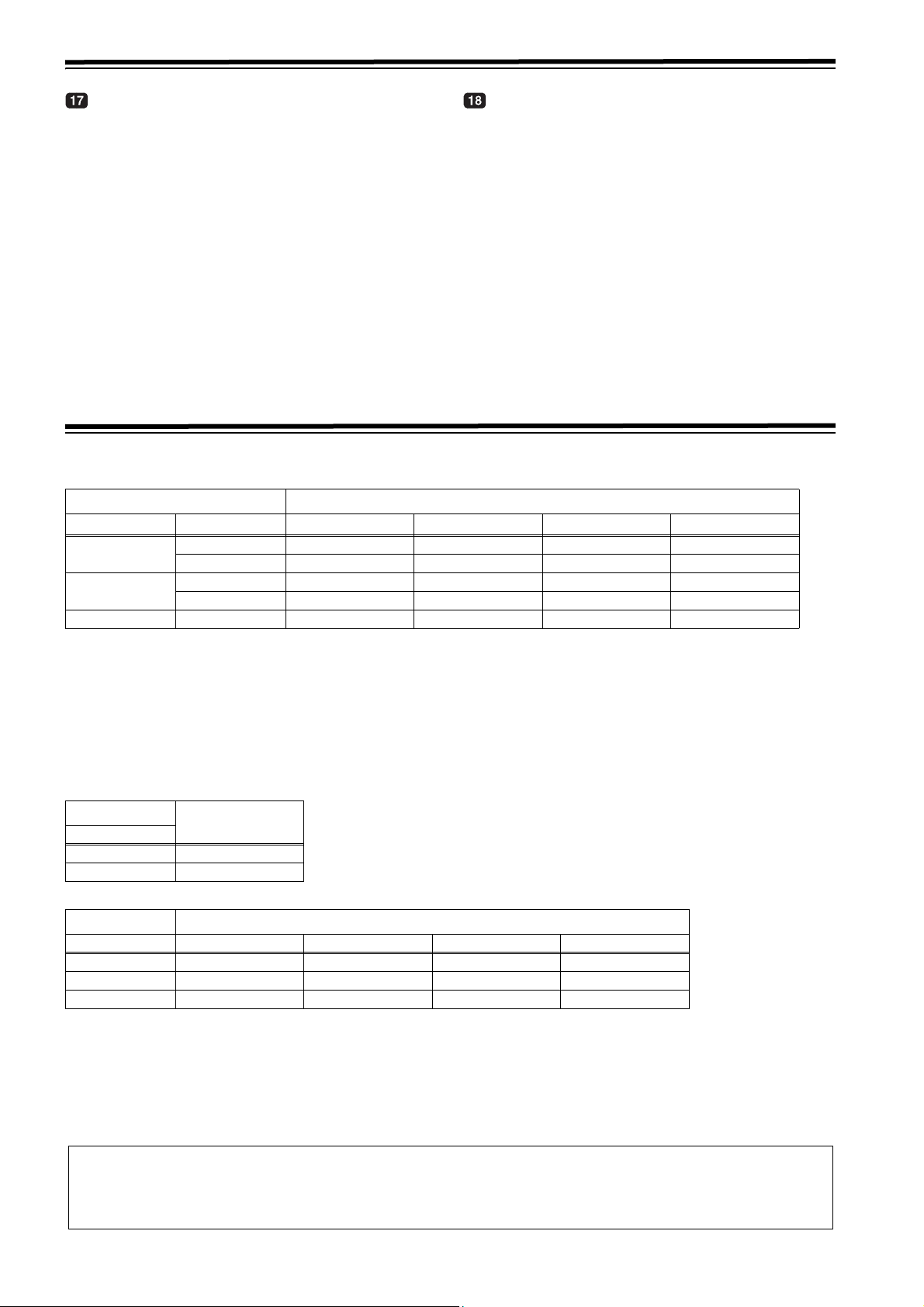
Reference signals
During tape playback, the video output reference signals are as shown in the table below.
In the 59.94 Hz/60 Hz or 50 Hz mode
Input signals Menu item No.031
REF_IN INPUT AUTO HD_REF SD_REF
HD_REF_IN
SD_REF_IN
None Not input Internal HD Internal HD Internal SD Internal HD
*1 If “1394” or “INT SG (internal standard signal)” is selected for the video input signal, the video output reference signal will always be
“Internal HD.”
Input HD_REF_IN HD_REF_IN Internal SD INPUT
Not input HD_REF_IN HD_REF_IN Internal SD Internal HD
Input SD_REF_IN Internal HD SD_REF_IN INPUT
Not input SD_REF_IN Internal HD SD_REF_IN Internal SD
<Notes>
z When “E-AUTO” is selected in menu No. 31 OUT REF, the unit operates as if “INPUT” is selected in edit mode or “AUTO” is
selected in modes other than the edit mode.
z When using the SD > HD up-converter and HD > HD cross-converter, input the HD tri-level sync signal that supports the
HD output format in order to initiate operation using HD_REF_IN.
INPUT*
1
In the 23.98 Hz/24 Hz mode
Input signals
REF_IN
HD_REF_IN HD_REF_IN
None Internal HD
In the 25 Hz (HD), 25 Hz (SD), 50 Hz (HD) or 50 Hz (SD) mode
Input signals Menu item No.031
REF_IN AUTO HD_REF SD_REF INPUT
HD_REF_IN HD_REF_IN HD_REF_IN Internal SD Internal HD
SD_REF_IN SD_REF_IN Internal HD SD_REF_IN Internal HD
None Internal HD Internal HD Internal SD Internal HD
<Notes>
z In the 25 Hz (HD) or 50 Hz (HD) mode, black signals are output from the SD SDI output and analog composite output
connectors.
z In the 25 Hz (SD) or 50 Hz (SD) mode, black signals are output from the HD SDI output and analog component output
connectors.
z All the HD SDI output, SD SDI output, video output, analog component output, audio output and TC output signals are
output in phase with the REF input.
Internal HD:
With HD tape playback as the reference, operation uses a 74 MHz clock signal in the free-run mode.
Internal SD:
With SD tape playback as the reference, operation uses a 4fsc clock signal in the free-run mode.
16
Page 17

Reference frequencies
During tape playback, the video output reference frequencies are as shown in the table below.
59.94 Hz/60 Hz operation specifications
Input signals Menu item No.031
REF_IN INPUT AUTO HD_REF SD_REF INPUT
Complies with
HD REF IN
frequency
Complies with
HD REF IN
frequency
Complies with
menu item No.030
frequency
Complies with
menu item No.030
frequency
Complies with
menu item No.030
frequency
59.94Hz
59.94Hz
59.94Hz
59.94Hz
59.94Hz
HD_REF_IN
SD_REF_IN
None Not input
Input
Not input
Input 59.94Hz
Not input 59.94Hz
Complies with
HD REF IN
frequency
Complies with
HD REF IN
frequency
Complies with
menu item No.030
frequency
<Notes>
z During SD tape playback, operation is not possible in the 60 Hz mode.
z When the HD SDI output signals are output at 60 Hz/24 Hz, the SD SDI signal is output in the NO SYNC status, and the
analog composite signals are output in black-and-white mode (burst OFF).
z All the HD SDI output, SD SDI output, analog composite output, analog component output, audio output and TC output
signals are output in phase with the REF input.
Complies with
INPUT
frequency
Complies with
menu item No.030
frequency
Complies with
INPUT
frequency
Complies with
menu item No.030
frequency
Complies with
menu item No.030
frequency
When “90H” is selected as the menu item No.26 HD SYS H ADV, the HD output is output with a phase 90H ahead of the SD
output.
When the SD REF signal is input, the REF input and SD output signals are inphase, and when the HD REF signal is input,
the REF input and HD output signalsare in-phase.
z The audio output and TC output signals are output in-phase with the HD output signals.
z With the 720p format, there is a phase difference of 120H.
17
Page 18
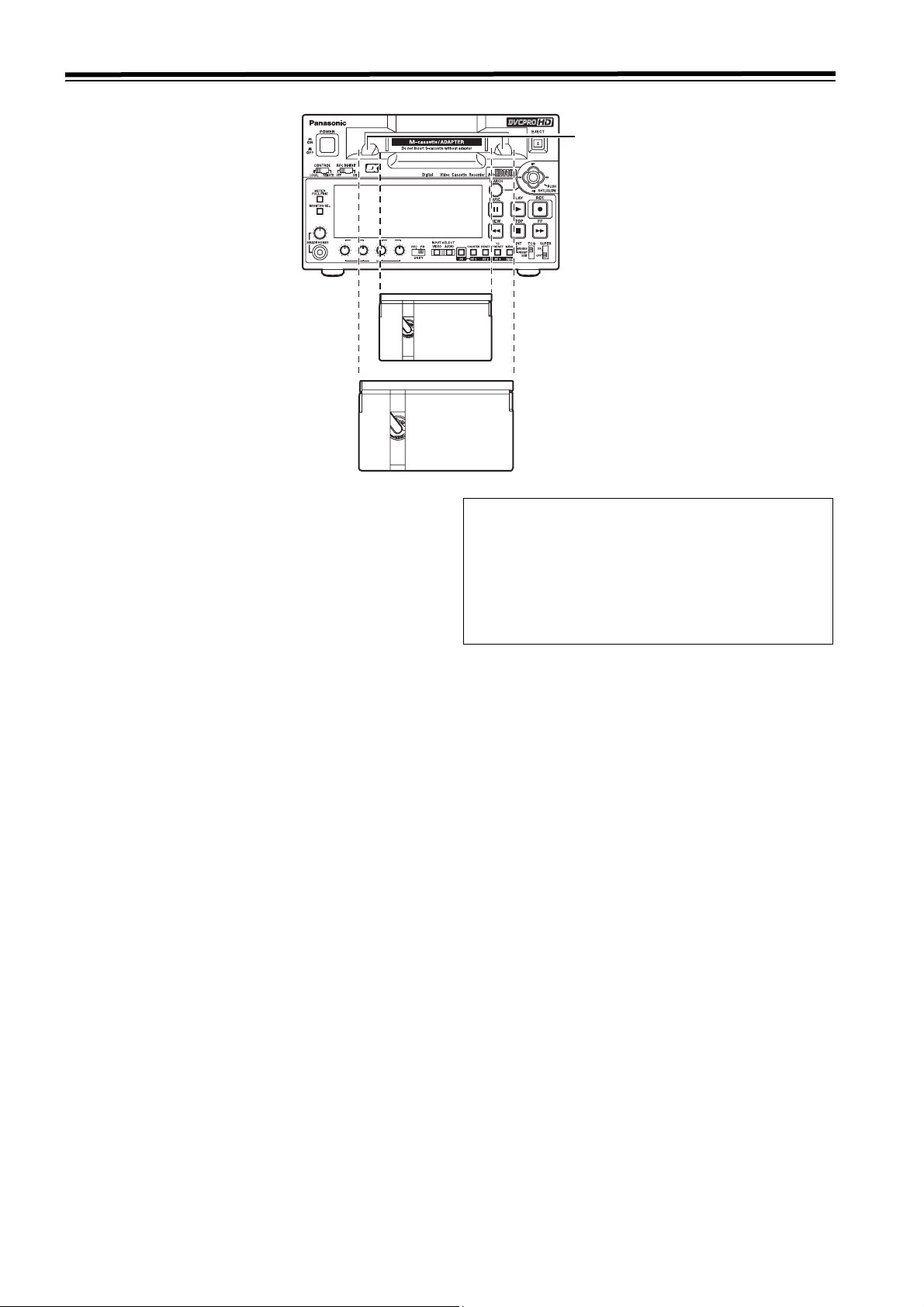
Tapes
REC
CH1 CH2 CH1 CH2
CH1/5 CH2/6
CH3/7 CH4/8
PB
M cassette guide
HD
PB
M cassette size
L cassette size
Consumer-use DV and DVCAM cassettes
(Standard DV and DVCAM cassettes, mini DV and
DVCAM cassettes)
z Use a cassette adapter (AJ-CS455P) when a mini DV or
DVCAM cassette is to be used.
Note that inserting a mini DV or DVCAM cassette without
the use of a cassette adapter will cause malfunctioning.
Also note that long-duration mini DV cassettes (80 minutes
in the standard mode and 120 minutes in the LP mode)
cannot be used.
z It is not possible to play back tapes which have been
recorded in the LP mode.
z When editing material recorded on a consumer-use DV or
DVCAM cassette, first record the material on a DVCPRO
tape or other tape used by VTRs for broadcast
applications.
z The maximum transport speed of a mini DV or DVCAM
cassette tape is 32k.
z The images may be subject to disturbance during the slow
motion playback of consumer-use DV and DVCAM
cassette tapes.
z From the perspective of protecting consumer-use DV and
DVCAM cassette tapes, minimize the number of times the
tapes are cued up at the same locations as much as
possible.
z When consumer-use DV and DVCAM cassette tapes are
used, the maximum time for STILL TIMER is set to 10
seconds.
It is recommended that tapes bearing the Panasonic
brand be used as the consumer-use DV tapes.
Align the center of the cassette with the
center of the insertion slot, and press it in
gently.
The cassette tape will load automatically.
<Notes on cassette insertion>
z Set the cassette level with the cassette slit and insert
straight.
z Do not put your hand in the cassette slit.
z Insert an M-cassette between the left/right M-cassette
guides.
z If the cassette slit is exposed to the strong direct rays of
the sun, a malfunction in the tape travel may occur.
M cassettes
Tapes capable of up to 33 minutes of recording or playback
(AJ-HP33EMG: for AJ-HD1400E)
L cassettes
Tapes capable of up to 64 minutes of recording or playback
(AJ-HP64ELG: for AJ-HD1400P and AJ-HD1400E)
18
Page 19
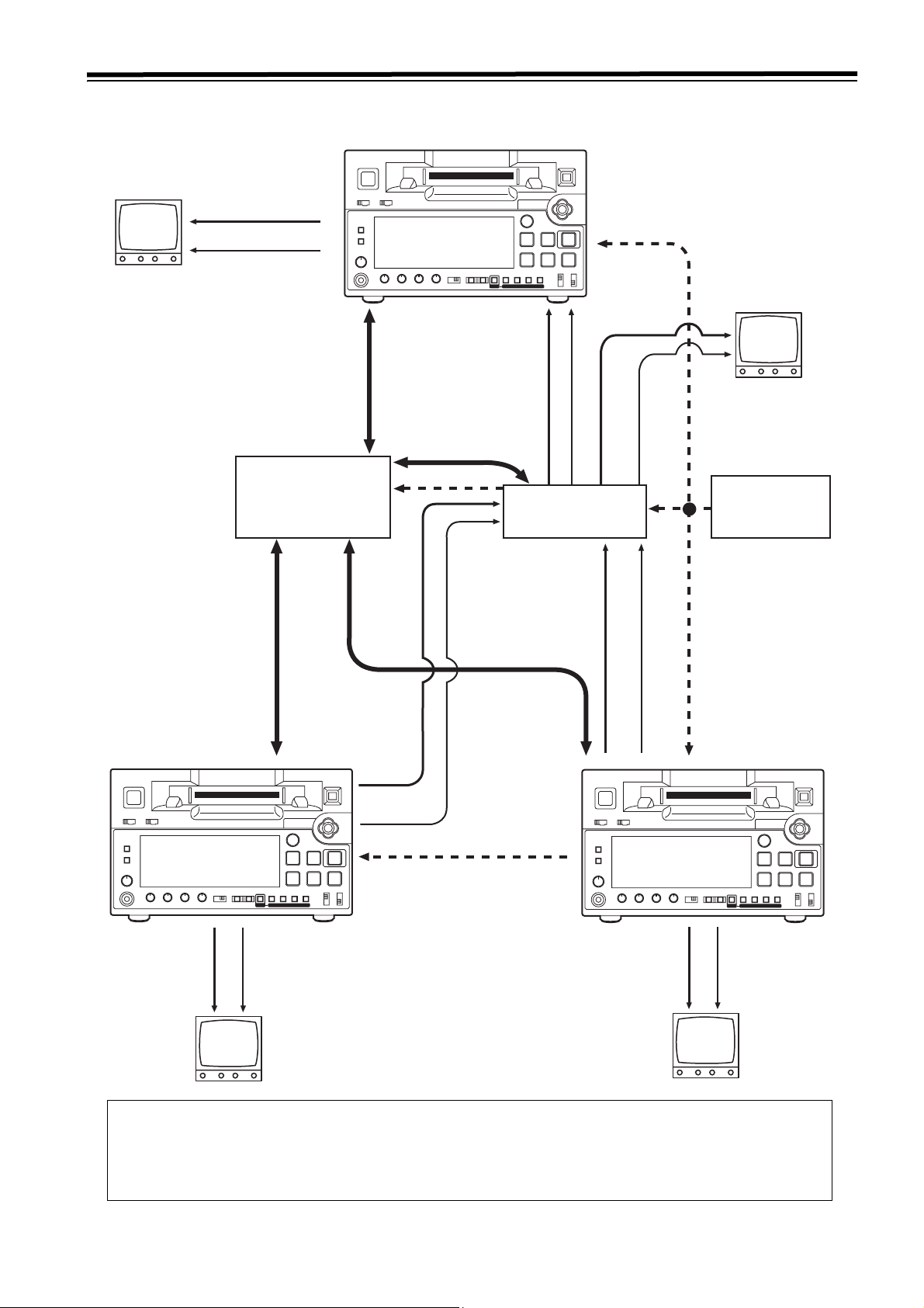
Connections
Example of connections with an editing controller
Recorder
AV m onitor
Analog composite
signals
Audio monitor
signals
Editing controller
AG-A850 etc.
To REMOTE CONTROL
connector
Remote signals
Video input signals
Audio input signals
AV switcher
AV monitor
Video monitor signals
Audio monitor
signals
Reference signal
generator
Source unit
Analog
composit
e signals
AV monitor
To REMOTE CONTROL
connector
Audio
monitor
signals
Remote signals
Video output signals
Audio output signals
To REMOTE CONTROL
connector
Reference signal
Source unit
composite
signals
AV m onitor
Reference signal
Audio
monitor
signals
Audio output signals
Video output signals
Analog
<Notes>
z When disconnecting the remote signals (9P) from one component and re-connecting them to another component,
check the settings,etc. of the editing controller.
z If the editing operation is executed via the 1394 connection, errors may occur in the editing.
z If the JOG/VAR operates at a half speed or less, errors may occur in the CTL count.
19
Page 20

IEEE1394 digital interface
Settings for this unit
Confirm that menu No. 882 DIF IN CH and No. 883 DIF OUT
CH of this unit are set to “AUTO.”
Input-output of the digital input signal is enabled when “59/
60” is selected in menu No. 25 SYSTEM FREQ and
operated in 59.94 Hz. Input-output of the digital input signal
is enabled when “50i/25P” is selected in menu No. 25
SYSTEM FREQ as well.
<Notes>
z The incoming signal is limited to the format selected in
menu No. 020 SYSTEM FORMAT.
z The output format is determined according to the list
shown below.
Playback format Output data format
DVCPRO HD-LP,
DVCPRO HD
DVCPRO50 DVCPRO50, DV*
DVCPRO DVCPRO, DV
DV, DVCAM DV
For EE mode or recording/editing
(Including scene-to-scene
continuity)
z Select a value other than "1394"
with the INPUT SELECT button
on the front panel.
* CH1/CH2 or CH3/CH4 can be selected as the output audio
channel.
With the following setting, the signal is not output from the
IEEE1394 digital interface.
z When “23/24,” “25 (HD),” “25 (SD),” “50 (HD),” or “50 (SD)” is
selected in menu No. 025 SYTEM FREQ
z When the unit operates in 60 Hz/24 Hz
DVCPRO HD,
DVCPRO50, DV*
DVCPRO HD*
Precautions for use
z Connect the interface with another device on a 1:1 basis.
z If the E-92 warning (1394 INITIAL ERROR) is displayed,
either re-connect the connecting cable or turn the VTR’s
power off and back on.
z The AV signals may be disrupted when the power of the
connected devices is turned on or off and when the
interface cable is connected or disconnected.
z When the input signals are switched or the mode is
transferred, it may take a few seconds for the system to
stabilize. Proceed with the recording operation only after
the system has stabilized.
z The following situation applies when recording is to be
performed by selecting the IEEE1394 digital interface
input, and it applies with the signals which are output by
the IEEE1394 digital interface.
The audio level control knobs on the front panel do not
work. The settings in menu No. 680/681/695 are
ignored and the blanking will not be applied.
When playback signals other than regular 1a speed
playback signals have been input, no guarantees are
made for the pictures and sound which will be
recorded or for the EE-type pictures and sound.
z The following situation applies when the video input
selection has been set as the IEEE1394 digital interface.
The SDI signals, the analog video output signals and
time code output signals become irregular in the EE
mode. Do not use these signals for recording
purposes. (The teletext signals and other signals
superimposed onto the video output signals also
become irregular.)
z During SLOW/STILL playback, unprocessed video and
audio signals are output as the IEEE1394 digital interface
output. When these video and audio signals are monitored
using another device, they may differ from the video and
audio signals played back by this unit.
When the equipment for non-linear editing is connected to
this unit, do not start any other application program than
software for the non-linear edit. Non-linear editing
equipment may garble the output video picture.
Be absolutely sure not to defeat the following
safeguards when connecting the IEEE1394
cable.
(1) Ensure that the unit and all devices to be
connected are grounded (or connected to a
common ground).
If the equipment cannot be grounded, first turn off
the power of all the connected devices, and then
disconnect and re-connect the IEEE1394 cable.
(2) When connecting the unit to a device equipped
with a 4-pin connector, connect the unit’s
connector (6-pin type) first.
(3) When making a connection to a PC equipped
with a 6-pin connector, connect the 1394 cable
so that it mates properly with the 1394
connector. Bear in mind that if the plug is
inserted the wrong way round, the unit may be
damaged as a result.
20
Page 21

VANC data recording/playback
VANC data recording
1 Detects the VANC data packets that multiplex recorded
in the following range of the Y stream of HD SDI.
1080i: L9–L20, L571–L583
720P: L9–L25
<Note>
HANC data packets are not be detected.
2 Records VANC data packets up to the following volume
in the VAUX region of the DVCPRO HD format in the
order of the earlier line.
1080i: 5760 word/frame
720P: 2880 word/frame
<Note>
Data packets that exceed the capacity will not be
recorded or played back.
3
Records the video signal from the HD SDI simultaneously.
<Note>
Recording and playback of VANC data only are not
possible.
VANC data playback
1 If the VTR mode is one of the following, VANC data will
be multiplexed to the Y stream of the HD SDI and will be
played back with the video signal.
z Normal playback mode
z Simultaneous playback mode
z Edit playback mode
z EE mode
<Notes>
z If an operation mode other than the above, such as FF,
REW, JOG, VAR, the video signal will only be played
back by muting VANC data.
z Playback of VANC data only is not possible.
2 VANC data packets will be multiplexed to the same line
of the multiplex line.
<Note>
For format conversion playback, the video signal only will
be played back by muting VANC data.
21
Page 22

Joystick and Variable Speed Playback
Joystick
2
HD
REC
CH3/7 CH4/8
PB
PB
REC/PB
CH1 CH2 CH1 CH2
CH1/5 CH2/6
1
4
3
4
1 Press the SEARCH button to activate the joystick.
When “STICK” has been selected as the menu item
No.100 SEARCH ENA setting, the joystick will be
activated without pressing the SEARCH button.
4 When the joystick is inclined upward, the tape travels in
1-frame increments in the forward direction; when it is
inclined downward, it travels in 1-frame increments in the
reverse direction.
Slow playback is performed if the stick is held at the top
or bottom position.
z If the SEARCH button is pressed while the joystick is
pressed to one side, the current speed is maintained
even if the joystick is released. Pressing the STOP,
PLAY, or other operation buttons cancels the fixed
speed operation.
<Notes>
z Noise may occur in the video images and voices may be
distorted when tape is replayed at a speed other than the
standard speed (1a).
z The PCM audio signal is played back in the –0.9a to
+1.0a speed range, while the CUE signal is played back
at all other speeds. (See menu No. 746 MONI CH SEL
3
(page 51) and No. 765 CUE OUT SEL (page 52))
Variable Speed Playback
Variable playback speeds are possible by operating the
controller if the 9P remote controller is connected to the
REMOTE CONTROL connector.
2 Press the joystick to switch between the SHTL mode and
SLOW mode.
3 When the joystick is inclined toward the right, the tape
can be played back in the forward direction at a variable
speed based on the angle that the stick is inclined. When
the stick is inclined toward the left, the tape is played
back in the reverse direction.
z SHTL mode:
The maximum speed which is established when the
joystick has been inclined at the maximum angle
corresponds to the speed which has been set by menu
item No.101 SHTL MAX.
z SLOW mode:
The speed ranges from –0.9a to +1.0a.
22
Page 23

PF (Programmable Function)
Three setup menu items can be registered in the PF buttons, and these buttons can then be used to change the setup menu
settings by a simple operating procedure.
Performing operations using the PF buttons
1 Open the setup menu by pressing the Menu button, and
move the cursor to the A00 MENU by tilting the joystick
down and then to the right.
2 Move the cursor to the item with the PF number to be
registered (A04 to A06) by tilting the joystick up and
down.
SETUP-MENU M ENU
<USER1> NO .A04 A02 P.ON LOA D OFF
¢
A04 PF1 ASSIG N 012
A05 PF2 ASSI GN 513
A06 PF3 ASSI GN -- END
3 When the joystick is pressed, a list of items which can be
set is displayed.
SETUP-MENU M ENU
<USER1> NO .A04A04 PF1 ASSIG N 012
¢
--- NO ASSIGN
001 LOCAL EN A
002 LOCAL TI MER
003 REMAIN S EL
008 CHARA H- POS
009 REMAIN S EL
010 CHARA V- POS
<Notes>
z The following menu items cannot be saved.
No. Menu item No. Menu item
05 ENCODER SEL 653 Y LEVEL (HD)
06 V LEVEL CTRL 654 Pb LEVEL (HD)
12 SYS H (HD) 655 Pr LEVEL (HD)
14 SYS SC (SD) 656 BK LEVEL (HD)
15 VO SYS SC (SD) 658 Y LEVEL (SD)
16 SD SYS SC (SD) 659 Pb LEVEL (SD)
18 SCH CORS (SD) 660 Pr LEVEL (SD)
19 SCH FINE (SD) 661 BK LEVEL (SD)
20 AV PHASE 662 V LEVEL
25 SYSTEM FERQ 663 C LEVEL
26 HD SYS H ADV
181 TYPE A NEAR
182 TYPE A END
183 TYPE B NEAR
184 TYPE B END
z As for the menu items registered in the PF button, when
the menu is not displayed due to change of settings in
menu No. 25 SYSTEM FREQ are changed, the registered
contents in the interlocked PF button will be in the “not
saved” state and cannot be displayed nor operated. Refer
to “Menus which are displayed” (page 32).
The settings for the PF buttons are retained but will be
updated once save operations are executed again.
HUE
(AJ-HD1400P)
664
C PHASE
(AJ-HD1400E)
SETUP LVL
(AJ-HD1400P)
665
BK LVL
(AJ-HD1400E)
4 Press the joystick to select the item at the cursor
position; the display will then return to the regular menu.
Operation using the PF buttons
1 When the PF button is pressed, the registered items are
displayed on the monitor screen which is output from the
VIDEO MON connector.
2 Press the PF1, PF2 or PF3 button that corresponds to
the item whose setting is to be changed. Each time the
button is pressed, the setting is updated in sequence.
PF1:SYS FORM AT 50M
PF2:INT SG CB75
PF3:-------- -- ---
3 When the PF button is pressed again, the regular display
is restored. If no operations are made, the display is also
restored automatically after five seconds elapse.
23
Page 24

Pause/Recording (Recording with pauses)
1 Press the PAUSE button during playback of the cassette
tape.
2 Press the REC button to move to the REC PAUSE mode.
When menu item No. 154 AUTO BACK is set to “REC-P”
or “ALL,” the tape is rewound for a few seconds from the
position where the PAUSE button is pressed.
4 Press the PAUSE button again to pause the recording.
When menu item No. 154 AUTO BACK is set to “REC-P”
or “ALL,” the tape is rewound for a few seconds from the
position where the PAUSE button is pressed, and then
paused.
5 By repeating the operation in 3 and 4 above, it is possible
to record with pauses.
3 Press the PAUSE button to start recording.
The tape runs to the position where the PAUSE button is
pressed as mentioned in 1 above, and recording starts.
Cue up
When recording with pauses, the time codes of the starting point and the stopping point of the recording are automatically
backed up. However, the “CTL” is selected by using the COUNTER button, and the control signals are backed up.
With the following button operation, it is possible to cue up to the starting and stopping points of the recording.
STOP + REW
Press the REW button while the STOP button is pressed
to cue up to the starting point of the recording.
STOP + FF
Press the REW button while the STOP button is pressed
to cue up to the starting point of the recording.
<Note>
If the time code is not successive, it is impossible to cue up
to the starting point of the recording properly. Execute the
following settings.
z Menu item No. 154 AUTO BACK:
“REC-P” or “ALL”
z Menu item No. 503 TCG MODE:
“REGEN” or “AUTO”
<Notes>
z In the backup operation, only the time codes of the last
event recorded with pause are stored.
z Even if the recording is stopped by pressing the STOP
button, the stopping point of the recording is backed up.
z Cueing up from a portion where nothing is recorded
cannot be executed properly.
z If the FF/REW button is pressed during the cue up
operation, the unit moves to the ordinary search mode.
z When the power is turned off, backup data stored when
starting the recording and completing the recording will be
cleared.
1 Execute the recording with pauses.
2 Press the REW button while the STOP button is pressed.
The tape cues up to the starting point of the recording
with an accuracy of ±1 frame.
3 Press the PLAY button to confirm the recording.
4 Press the FF button while the STOP button is pressed.
The tape cues up to the stopping point of the recording
and stops 5 to 10 frames before the stopping point.
5 Press the PAUSE button and then the REC button to
move to the REC PAUSE mode.
The tape cues up to the stopping point of the recording
and stops 5 to 10 frames before the stopping point.
24
Page 25

Repeat playback
Setting the BEGIN and END points
1 Press the MENU button.
2 Select menu item No. 161 CTL (TC) BGN or No. 162
END, and tilt the joystick right/left while pressing the
SEARCH button.
By operating the joystick, the user can choose whether
or not to set the BEGIN and END points. “--:--:--:--”
appears on the display when the points are not set. If
repeat playback is initiated in this state, the tape start will
serve as the BEGIN point, and the tape end will serve as
the END point.
3 Press the joystick while the setting is displayed. The
changed digits flash on the display.
4 Select TC or CTL using the COUNTER button.
5 Incline the joystick to the left or right, and select the digits
to change (flashing).
The frame digits cannot be selected. “00” is always
displayed for these digits.
When the joystick is now inclined upward or downward,
the value of the digits changes.
The counter display is reset to 00:00:00:00 when the
RESET button is pressed.
6 After the settings have been completed, press the
joystick.
7 Press the MENU button.
<Note>
The settings for the BEGIN and END points are not stored in
user default. Even if the factory settings and/or the user
defaults are loaded, the settings for the BEGIN and END
points are not revised. For user defaults, refer to “Setup
(initial settings)” (page 27).
Setting the repeat playback mode
1 Press the MENU button.
2 Select menu item No.160 MEMORY MODE, and select
the repeat playback mode.
Item setting Description of operation
OFF Normal operation
M-STOP
REPT1
CONT
When the tape is fast forwarded or
rewound, it stops near the BEGIN
point.
When the tape is played as far as the
END point, it is rewound to the BEGIN
point where it stops.
When the tape is played as far as the
END point, it is rewound to the BEGIN
point and played, and this sequence of
operations is repeated.
3 Press the MENU button.
A confirmation screen now appears. The settings are
stored in the memory if the PLAY button is now pressed.
<Notes>
z The picture quality deteriorates when repeat playback is
initiated for the same tape over and over again. As a
general rule of thumb, replace the tape with a new one
after playing back the tape for about 100 times.
z The output images to be displayed while the tape is being
rewound to the BEGIN point in the repeat playback mode
can be set using menu item No.163 REPT MODE.
If “FREEZE” is selected as the REPT MODE setting and
the tape end has been set as the END point, the playback
image will not be frozen properly. Set the END point at a
place on the tape where images have been recorded.
z If the counter display mode (TC or CTL), which was
established when menu item No.161 CTL (TC) BGN and
No.162 END were set, is different from the counter display
mode (TC or CTL) in which repeat playback is to be
initiated, the repeat lamp flashes, and the repeat playback
operation cannot be performed.
z When repeat playback is to be initiated using a consumer-
use DV and DVCAM tapes, the unit will not operate even if
“CONT” has been selected as menu item No.160
MEMORY MODE setting.
25
Page 26

Recording from a variable frame rate camera
AABBCCDDEEF
00 01 02 03 04 05
ABBCCDDEEE
00 01 02 03 04
Recording the HD SDI output signal from a variable frame rate camera
Connect the HD SDI (720/30Pover 59.94P) output of the
variable frame rate camera to the HD SDI input connector of
this unit.
1 Select “SLTC” in menu No. 032 REC REF.
Detect the frame information from the superimposed
time code in the HD SDI signal to prevent displacement
of the field.
2 Adjust the following settings to activate the two settings.
z Menu No. 25 SYSTEM FREQ: 59/60
z Menu No. 020 SYS FORMAT: 720p
z INPUT SELECT button on the front panel: HDSDI
3 Change the mode for this unit to REC PAUSE mode.
4 Press the PAUSE button while confirming the HD SDI
output image of the variable frame rate camera to start
recording.
The time code is recorded to maintain the continuity of
the recorded tape.
The superimposed user bits for the HD SDI signal is
recorded.
<Note>
Through the settings in menu No. 032 REC REF, the time
code and the user bits recorded on the tape are as follows.
Field displacement
There is no discriminant information to differentiate between
the first field and the second field in the HD SDI signal of
720P. Accordingly, it is usually necessary to synchronize the
HD SDI signal transmission equipment to the recording
equipment with the reference signal from SD. If not
synchronized, there is a risk of generating displacement
(image frame fails to match the time code) with 1/2
probability described as follows.
Variable frame rate camera
720/30P over 59.94P
SLTC:
The time code is recorded to maintain the continuity of
the recorded tape.
The superimposed user bits for the HD SDI signal is
recorded.
The following settings are then invalid.
z TCG switch on the front panel
(REGEN/PRESET/EXT)
z Menu No. 503 TCG_MODE
(SW/FREE)
z Menu No. 505 TCG_REGEN
(TC&UB/TC/UB)
z Menu No. 507 TC_SOURCE
(EXT_L/SLTC/SVITC)
NORMAL:
Time code and user bits are recorded according to the
following settings.
z TCG switch on the front panel
(REGEN/PRESET/EXT)
z Menu No. 503 TCG_MODE
(SW/FREE)
z Menu No. 505 TCG_REGEN
(TC&UB/TC/UB)
z Menu No. 507 TC_SOURCE
(EXT_L/SLTC/SVITC)
AJ-HD1400
Video output of variable
frame rate camera
Time code output of
variable frame rate camera
Record image of VTR
Record time code of VTR
To prevent displacement of this field, select “SLTC” in menu
No. 032 REC REF when recording the HD SDI output signal
from a variable frame rate camera (720/30P over 59.94p)
with this unit.
26
Page 27

Setup (initial settings)
This unit’s main settings can be performed and checked using the on-screen menus which are displayed on the video monitor
connected to the unit.
It is also possible to set and confirm using the item number and the setting number or the item name, which are displayed on
the display part on the front panel.
Furthermore, a user setting memory in which to store three sets of settings is provided, enabling the desired settings to be
stored for future use.
5
2, 3, 4
HD
REC
PB
PB
CH3/7 CH4/8
CH1 CH2 CH1 CH2
CH1/5 CH2/6
1, 7
Setting method using the on-screen menus
1 Press the MENU button.
SETUP-MENU MAIN is displayed on the video monitor,
and the names of the main menu items are displayed in
the counter display.
5 Incline the joystick right and left while pressing the
SEARCH button at the changing position.
The set value on the settings screen and the set value in
the counter display flash; the value changes each time
the joystick is inclined right and left. When the set value
is displayed, return the joystick.
In order to return the set value to the factory settings,
press the RESET button while pressing the SEARCH
button.
6 To change the other items, repeat the process 4, 5, and
6.
7 Press the MENU button.
z When the set value is not changed, the display of the
menu screen disappears.
z When the set value is changed, a confirmation screen
will be displayed.
z Press the PLAY button to save the changes of the set
value.
z Press the STOP button to cancel the change of the set
value.
SETUP-MENU SE T OK?
YES<PLAY>/ NO<STOP>
SETUP-MENU MA IN
NO.00
¢
00 SYSTEM
000 BASIC
100 OPERAT ION
200 INTERF ACE
300 EDIT
400 TAPE P ROTECT
500 TIME C ODE
600 VIDEO
700 AUDIO
2 Incline the joystick up and down to select the main menu
item.
The cursor (¢) for the main menu items on the select
screen moves up and down and the names of main
menu items are displayed on the counter display.
3 Incline the joystick toward the right to move the cursor on
the settings screen to each item.
The settings screen for each item is displayed on the
video monitor, and the item number in the counter
display will flash. When the FF button is pressed for
about 1.5 seconds, the item name will be displayed in the
counter display. When the FF button is pressed for about
1.5 seconds again, the display returns to the item
number.
In order to return to the SETUP-MENU MAIN screen,
incline the joystick toward the left.
Returning to the factory settings
1 Press the MENU button.
A select screen for the major menu items is displayed on
the video monitor and the names of the major menu
items are displayed in the counter display.
2 Press the RESET button.
The unit is now set to the default setting mode, and the
default setting screen now appears on the video monitor.
SELECT MODE
¢ 0 ESCAPE
1 LO AD
2 SA VE
3 PR OTECT
4 Incline the joystick up and down to select the item to
change the setting.
The cursor (¢) on the select screen moves up and down,
and the item number flashes on the counter display.
27
Page 28

Setup (initial settings) (continued)
3 Incline the joystick up and down to adjust the cursor in
the default settings screen to the “LOAD” position and
press the joystick. The mode for this unit changes to the
LOAD mode, the LOAD screen is displayed on the video
monitor, and the item name is displayed in the counter
display.
SETUP-MENU < LOAD>
¢ NO
FACT ORY
USER (ALL)
USER (NOT SYSTEM)
4 Incline the joystick up and down to adjust the cursor in
the LOAD screen to the “FACTORY” position and press
the joystick.
z If this operation is made after moving the cursor to
“FACTORY,” values for all menus except the SYSTEM
menu will return to the factory settings.
z When the cursor is moved to “NO” and this operation is
performed, the display returns to the menu screen
without restoring the factory settings.
5 The confirmation screen is displayed on the video
monitor.
z Press the PLAY button to save the change of the set
value.
z Press the STOP button to cancel the change of the set
value.
SETUP-MENU < LOAD>
FACTORY OK?
YES<PLAY>/N O<STOP>
Setting the user defaults
1 Press the MENU button.
A select screen for major menu items is displayed on the
video monitor, and the names are displayed in the
counter display.
2 Follow the procedure described in “Setting method using
the on-screen menus” 2–6 and adjust the desired
settings.
3 Press the RESET button.
The mode for this unit will change to the default setting
mode, and the default setting screen will be displayed on
the video monitor.
SELECT MODE
¢ 0 ESCAPE
1 LO AD
2 SA VE
3 PR OTECT
4 Incline the joystick up and down to adjust the cursor in
the default settings screen to the “SAVE” position and
press the joystick.
The mode for this unit changes to the SAVE mode, the
SAVE screen is displayed on the video monitor, and the
item name is displayed in the counter display.
SET-UP MENU <SAVE>
¢ NO
USER 1(ALL)
USER 2(ALL)
USER 3(ALL)
USER 1(NOT SYSTEM)
USER 2(NOT SYSTEM)
USER 3(NOT SYSTEM)
6 Press the MENU button.
z When the set value is not changed, the display of the
menu screen disappears.
z When the set value is changed, a confirmation screen
will be displayed.
z Press the PLAY button to save the change of the set
value.
z Press the STOP button to cancel the change of the set
value.
SETUP-MENU SE T OK?
YES<PLAY>/N O<STOP>
5 Incline the joystick up and down to adjust the cursor on
the SAVE screen to the “USER ¢ (ALL)” position (¢
each value from 1 to 3.) and press the joystick.
z When storing a set value other than SYSTEM menu in
memory, move the cursor to “USER ¢ (NOT
SYSTEM)” (¢ each value from 1 to 3.) and press the
joystick.
z To cancel the operation, move the cursor to “NO” and
press the joystick.
6 Confirmation screen for SAVE is displayed.
z Press the PLAY button to save the setting.
z Press the STOP button if the set value is not saved.
SET-UP MENU <SAVE>
USER1(ALL) O K?
YES<PLAY>/N O<STOP>
28
Page 29

Setup (initial settings) (continued)
7 Press the MENU button.
z When the set value is not changed, the display of the
menu screen disappears.
z When the set value is changed, a confirmation screen
will be displayed.
z Press the PLAY button to save the changes of the set
value.
z Press the STOP button to cancel the change of the set
value.
SETUP-MENU SE T OK?
YES<PLAY>/N O<STOP>
User default loading method
1 Press the MENU button.
A select screen for the major menu items is displayed on
the video monitor, and the names are displayed in the
counter display.
4 Incline the joystick up and down to adjust the cursor on
the LOAD screen to the “USER ¢ (ALL)” (¢ each value
from 1 to 3.) position and press the joystick.
z When loading a set value other than SYSTEM menu in
memory, move the cursor to “USER ¢ (NOT
SYSTEM)” (¢ each value from 1 to 3.) and press the
joystick.
z To cancel the operation, move the cursor to “NO” and
press the joystick.
5 LOAD confirmation will be displayed.
z To load the set value, press the PLAY button.
Indications on the menu will disappear.
z To prevent loading of the set value, press the STOP
button. Indications on the menu will disappear.
SET-UP MENU <LOAD>
USER1(ALL) O K?
YES<PLAY>/N O<STOP>
2 Press the RESET button.
The unit is now set to the default setting mode, and the
default setting screen now appears on the video monitor.
SELECT MODE
¢ 0 ESCAPE
1 LO AD
2 SA VE
3 PR OTECT
3 Incline the joystick up and down to adjust the cursor on
the default settings screen to the LOAD position and
press the joystick.
The mode for this unit changes to the LOAD mode, the
LOAD screen is displayed on the video monitor, and the
item name is displayed in the counter display.
SET-UP MENU <LOAD>
¢ NO
USER 1(ALL)
USER 2(ALL)
USER 3(ALL)
USER 1(NOT SYSTEM)
USER 2(NOT SYSTEM)
USER 3(NOT SYSTEM)
29
Page 30

Setup (initial settings) (continued)
Menu protection method
By switching to the menu protect mode, it is possible to
disable the setup menu even if the MENU button on the front
panel is pressed.
1 Press the MENU button.
A select screen for the major menu items is displayed on
the video monitor, and the names are displayed in the
counter display.
2 Press the RESET button.
The unit will switch to the default setting mode, and the
default screen will be displayed on the video monitor.
SELECT MODE
¢ 0 ESCAPE
1 LO AD
2 SA VE
3 PR OTECT
3 Tilt the joystick up/down to move the cursor to the
“PROTECT” position on the default screen and then
press the joystick.
The unit will switch to the LOAD mode, and the LOAD
screen will display on the video monitor. The item names
will appear on the counter display.
Menu protection release method
1 Press the MENU button when pressing the COUNTER
button on the front panel.
A select screen for the major menu items is displayed on
the video monitor, and the names are displayed in the
counter display.
2 Execute the procedures from 2 to 3 described in the
“Menu protection method.”
The unit will be set to the menu protect setting mode, and
the display for confirming menu protection will appear on
the video monitor.
MENU PROTECT OK?
YES<PLAY>/N O<STOP>
3 Press the STOP button.
The menu is displayed.
4 Press the MENU button.
The menu disappears, and the menu protect mode is
released.
MENU PROTECT OK?
YES<PLAY>/N O<STOP>
4 Press the PLAY button.
The menu is displayed.
5 Press the MENU button.
The menu disappears and the unit will switch to the
menu protect mode.
z If the MENU button is pressed while the menu protect
mode is set, the message <MENU PROTECT> is
displayed on the video monitor and the menu is
displayed.
<Note>
To enable ordinary menu operation while the menu
protection mode is set, press the MENU button when
pressing the COUNTER button on the front panel.
30
Page 31

Setup (initial settings) (continued)
System frequency switching
<Selection of the record and playback format and the synchronizing signal depends on the operation mode>
NO.25
SYSTEM
FERQ
59/60
50i/25P
23/24 None
25 (HD) None 720/25p over 60p
25 (SD) None 720/25p over 60p
50 (HD) None 720/50p over 60p
50 (SD) None 720/50p over 60p
Recordable format Playback permissible format Synchronized signal
1080/59.94i (HD_LP)
720/59.94p (HD_LP)
720/60.00p (HD_LP)
(Only the variable frame rate
signal can be recorded.)
1080/50i (HD_LP)
720/50p (HD_LP)
1080/59.94i
1080/60i
720/59.94p
720/60.00p
480/59.94i (50M, 25M, DV, DVCAM)
1080/50i
720/50p
576/50i (50M, 25M, DV, DVCAM)
576/25p over 50i (50M, 25M, DV)
1080/23.98p over 59.94i [2:3 mode]
1080/23.98p over 59.94i [2:3:3:2 advance mode]
720/23.98p over 59.94p
720/24p over 60.00p
480/23.98p over 59.94i [2:3 mode]
480/23.98p over 59.94i [2:3:3:2 advance mode]
HD_REF (59.94Hz, 60Hz)
SD_REF (59.94Hz)
According to the setting in menu
No. 031 OUT REF.
HD_REF (50Hz)
SD_REF (50Hz)
According to the setting in menu
No. 031 OUT REF.
HD_REF (47.96Hz, 48Hz)
HD_REF (50Hz)
SD_REF (50Hz)
According to the setting in menu
No. 031 OUT REF.
HD_REF (50Hz)
SD_REF (50Hz)
According to the setting in menu
No. 031 OUT REF.
HD_REF (50Hz)
SD_REF (50Hz)
According to the setting in menu
No. 031 OUT REF.
HD_REF (50Hz)
SD_REF (50Hz)
According to the setting in menu
No. 031 OUT REF.
Procedure for shifting the system frequency
To shift the system frequency execute the following operations.
1 Change the set value of menu item No. 25 SYSTEM
FREQ. For the method to change the set value, refer to
"Setting method using the on-screen menus" (page 27) .
Once the set value is changed, the outer frame of the
display part of SYSTEM FREQ and the characters in
SYSTEM on the front display panel start flashing.
SYSTEM
59.94 60
50/25PsF
24
23.98
50
25
HD
SD
2 Press the MENU button.
3 The confirmation screen is displayed to enable the
changed set value.
SETUP-MENU SE T OK?
YES<PLAY>/N O<STOP>
S
ystem menu item No.
(SYSTEM FREQ)
has been changed.
z To enable the change to set value, press the PLAY
button. Then the system resumes and starts again in
the selected mode.
z To disable the change to the set value, press the STOP
button. Any other changes in the set up menu items
are also disabled.
<Note>
If the system is restarted when a cassette remains in the
unit, the cassette will automatically be ejected.
setting
25
31
Page 32

Setup menus
Menus which are displayed
The menus displayed differ depending on the setting selected for menu item No.25 SYSTEM FREQ.
NO. Item
59/60 23/24 50i/25P 25 (HD) 25 (SD) 50 (HD) 50 (SD)
05 ENCODER SEL
06 V LEVEL CTRL
12 SYS H (HD)
14 SYS SC (SD)
15 VO SYS H (SD)
16 SD SYS H (SD)
18 SCH COAR (SD)
19 SCH FINE (SD)
20 AV PHA SE
25 SYSTEM FREQ
26 HD SYS H ADV No No No No No No
001 LOCAL ENA
002 TAPE TI M E R No No No No No
003 REMAIN SEL
005 SUPER
006 DISPLAY SEL
007 CHARA H-POS
008 CHARA V-POS
009 CHARA TYPE
020 SYS FORMAT No No No No No
022 PB FORMAT
023 FORMAT SEL
030 HD FREQUENCY No No No No No
031 OUT REF No
032 REC REF No No No No No No
100 SEARCH ENA
101 SHTL MAX
102 FF. REW MAX
104 REF ALARM
105AUTO EE SEL No NoNoNoNo
106 EJECT EE SEL
107 EE MODE SEL No No No No No
108 PLAY DELAY
109 CAP. LOCK No No No No No
110 AUTO REW
112 FRZ MODE SEL
114 REC INH LAMP
115 EJECT SW INH No No No No No
118 SP MODE INH No No No No No
119 CONFI REC No No No No No
134 ARARM BEEP
140 OUTPUT No No No No No
152 HUMID OPE
154 AUTO BACK No No No No No
155 AUTO REC No No No No No
160 MEMORY MODE
161 CTL BGN/TC BGN
162 END
163 REPT MODE
180 BATTERY SEL
181 TYPE-A NEAR
182 TYPE-A END
183 TYPE-B NEAR
Menu No.25 SYSTEM FREQ
32
Page 33

Setup menus (continued)
NO. Item
184 TYPE-B END
190 V IN SEL INH No No No No No
191 A IN SEL INH No No No No No
202 ID SEL
302 CONFI EDIT No No No No No
303 AUD EDIT IN No No No No No
304 AUD EDIT OUT No No No No No
307AFTER CUE-UP No NoNoNoNo
320 EDIT RPLCE1 No No No No No
321 EDIT RPLCE2 No No No No No
322 EDIT RPLCE3 No No No No No
323 EDIT RPLCE4 No No No No No
324 EDIT RPLCEC No No No No No
400 STILL TIMER
401 SRC PROTECT
402 DRUM STDBY
403 STOP PROTECT
500 VITC BLANK No No No
501 VITC POS-1 No No No
502 VITC POS-2 No No No
503 TCG MODE No No No No No
504 RUN MODE No No No No No
505 TCG REGEN No No No No No
506 REGEN MODE No No No No No
507 EXT TC SEL No No No No No
508 BINARY GP No No No No No
509 PHASE CORR
510 TCG CF FLAG No No No No No
511 DF MODE No No No No No No
512 TC OUT REF No No No No No
513 VITC OUT
514 HD EMBD VITC No No
515 HD EMBD LTC No No
601 VIDEO INT SG No No No No No
602 SDI IN MODE No No No No No
603 V-MUTE SEL
604 FREEZE SEL
615 V OUT SEL No No No No
619 V_FILTER No No No No No No
620 DOWNCON MODE No No
621 UPCONV MODE No No No No
626 D/C ENH H No No
627 D/C ENH V No No
628 U/C ENH H No No No No
629 U/C ENH V No No No No
630 1080i>HD_OUT No NoNoNoNo
632 720p>HD_OUT No No No No
636 SD>HD_OUT No NoNoNoNo
650 STYLE
651 HUE STYLE (SD) No No No No No
653 Y LVL (HD)
654 Pb LVL (HD)
655 Pr LVL (HD)
656 BK LVL (HD)
658 Y LVL (SD)
659 Pb LVL (SD)
660 Pr LVL (SD)
59/60 23/24 50i/25P 25 (HD) 25 (SD) 50 (HD) 50 (SD)
Menu No.25 SYSTEM FREQ
33
Page 34

Setup menus (continued)
NO. Item
661 BK LVL (SD)
662 V LEVEL
663 C LEVEL
664 HUE
665 SETUP LVL
676 BLK CLIP No No No No No
680 CC (F1) BLANK No No No No No No
681CC (F2) BLANK NoNoNoNoNoNo
682 VO SETUP (HD) (For AJ-HD1400P) No No No No No
683 VO SETUP (SD) (For AJ-HD1400P) No No No No No
684 EDH (SD) No No
685 ESR MODE (SD) No No No No No
686 CCR MODE (SD) No No No No No
687 SDI INDEX 0 No No No
689 COMP MODE No No No No No No
690 UMID REC No No No No No
691 UMID GEN No No No No No
692UMID POS No NoNoNoNo
693 GAMMA SEL
695 BLANK LINE No No No No No
701 CH1 IN LV No No No No No
702 CH2 IN LV No No No No No
706 CH1 OUT LV
707 CH2 OUT LV
710 MONIL OUT LV
711 MONIR OUT LV
712 MONI OUT
724 REC CH3/4 No No No No No
730 REC CUE No No No No No
731 PB FADE
732 EMBEDDED AUD
746 MONI CH SEL
750 ANA CH1/2 SEL
759DV PB ATT No NoNoNoNo
760 REC PT MUTE No No No No No
762 AUD RATE CON
765 CUE OUT SEL
781 IN IMP SEL No No No No No
782 EMB CH SEL
783 AUDIO CH SEL
784 MONI SEL INH
880 DIF SPEED No No No No No
882 DIF IN CH No No No No No
883 DIF OUT CH No No No No No
886 DIF CONFIG No No No No No
890 DIF AUD OUT No No No No No
891 DIF DV AUDIO No No No No No
892 DIF SIG CMD No No No No No
894 HD>DIF OUT No No No No No
895 50M>DIF OUT No NoNoNoNo
896 25M>DIF OUT No No No No No
899DIF SUPER No NoNoNoNo
A02 P. O N L O AD
A04 PF1 ASSIGN
A05 PF2 ASSIGN
A06 PF3 ASSIGN
59/60 23/24 50i/25P 25 (HD) 25 (SD) 50 (HD) 50 (SD)
Menu No.25 SYSTEM FREQ
34
Page 35

Setup menus (continued)
Video output signal adjustments
The control matrix for the adjustments is shown in the table
below.
This function is not available for IEEE1394 digital output.
When “CMPNT” has been selected as the menu item No.650
STYLE setting
Setting Adjustment item
05:
ENCODER
SEL
LOCAL
BOTH
06:
V LEVEL
CTRL
HD
BOTH
HD
SD AJ-HD1400
BOTH
653: Y LVL (HD)
654: Pb LVL (HD)
655: Pr LVL (HD)
656: BK LVL (HD)
AJ-HD1400 AJ-HD1400SD
External encoder
remote controller/
AJ-HD1400
External encoder
remote controller/
AJ-HD1400
658: Y LVL (SD)
659: Pb LVL (SD)
660: Pr LVL (SD)
661: BK LVL (SD)
AJ-HD1400
External encoder
remote controller/
AJ-HD1400
External encoder
remote controller/
AJ-HD1400
AJ-HD1400:
Only adjustments of the setup menu items are
performed.
External encoder remote controller/AJ-HD1400:
Adjustments can be performed from both the external
encoder remote controller and setup menus.
When “CMPST” has been selected as the menu item No.650
STYLE setting
Setting Adjustment item
05:
ENCODER
SEL
LOCAL
BOTH
06:
V LEVEL
CTRL
HD
BOTH
HD
SD
BOTH
662: V LEVEL
663: C LEVEL
664: HUE
665: SETUP LVL
AJ-HD1400SD
External encoder
remote controller/
AJ-HD1400
AJ-HD1400:
Only adjustments of the setup menu items are
performed.
External encoder remote controller/AJ-HD1400:
Adjustments can be performed from both the external
encoder remote controller and setup menus.
<Note>
Use the MT-200/2000 (manufactured by Musashi and
recommended by Panasonic) as the external encoder
remote controller. However, its VIDEO PHASE, SYNC
PHASE and SC PHASE controls will not work.
During menu operations and operations using the PF
function, operations from the external encoder remote
controller cannot be accepted.
<Notes>
z Use the AJ-ER50 as the external encoder remote
controller. However, its “VIDEO PHASE” and “SYNC
PHASE” controls will not work.
z During menu operations and operations using the PF
function, operations from the external encoder remote
controller cannot be accepted.
35
Page 36

Setup menus (continued)
SYSTEM
No./Item Description of setting
05
ENCODER
SEL
06
V LEVEL
CTRL
12
SYS H
(HD)
14
SYS SC
(SD)
15
VO SYS H
(SD)
For setting whether to perform the various
adjustments for the video output signals using this
VTR or using an external encoder remote controller.
0001 LOCAL
The various adjustments for the video output
signals are performed using this VTR.
0002 BOTH :
The various adjustments for the video output
signals are performed using both this VTR and an
external encoder remote controller.
<Notes>
z For video adjustments, refer to “Video output signal
adjustments” (page 35).
z If the signals are adjusted with the external
encoder remote controller, the adjusted values are
reflected in the setup menu. However, the adjusted
numerical values will not be stored unless about 1
minute has elapsed after completion of the
adjustment operation. If the unit is turned off after
executing the adjustments with the external
encoder remote controller, it is necessary to wait
about 1 minute before turning off the power.
z Settings in this menu are not effective for the
IEEE1394 digital output.
For selecting what is to be controlled when the video
output level is to be adjusted by an external encoder
remote controller.
0000 HD :
The HD video output level can be adjusted.
0001 SD :
The SD video output level can be adjusted.
0002 BOTH :
Both the HD and SD video output levels can be
adjusted.
For adjusting the system phase of the HD SDI output
signals. (in 13.5 ns increments).
– :Phase advances.
+ :Phase delays.
0000 –1100
: :
1100
: :
2200 1100
<Notes>
z When menu item No. 25 SYSTEM FREQ is set to
50i/25P, 25 (HD), 25(SD), 50 (HD) or 50 (SD), the
setting range is from –1320 - 0
z When menu item No. 25 SYSTEM FREQ is set to
23/24, the setting range is from –1375 - 0
For adjusting the system phase of the analog
composite output and SD SDI output signals (total
variable range of over ±180 degrees).
– :Phase advances.
+ :Phase delays.
0000 –108
: :
0108
: :
0216 108
For adjusting the system phase of the analog
composite output signals (in 37 ns increments).
– :Phase advances.
+ :Phase delays.
0000 –858
: :
0858
: :
1716 858
<Note>
The setting range is –864 to 0 to 864 when 50i/25P,
25 (HD) or 25 (SD) is selected as the menu item
No.25 SYSTEM FREQ setting.
:
0
0
0
- 1320.
- 1375.
No./Item Description of setting
16
SD SYS H
(SD)
18
SCH
COAR
(SD)
19
SCH FINE
(SD)
20
AV
PHASE
For adjusting the system phase of the SD SDI output
signals (in 37 ns increments).
– :Phase advances.
+ :Phase delays.
0000 –858
: :
0858
: :
1716 858
<Note>
The setting range is –864 to 0 to 864 when 50i/25P,
25 (HD) or 25 (SD) is selected as the menu item
No.25 SYSTEM FREQ setting.
For adjusting the SCH (sub-carrier to horizontal)
phase of the analog composite output signals (4
positions in 90-degree increments).
The SC phase changes, and the H phase remains
unchanged.
0000 0
0001 90
0002 180
0003 270
For adjusting the SCH (sub-carrier to horizontal)
phase of the analog composite output signals
(variable range of over ±45 degrees).
The SC phase changes, and the H phase remains
unchanged.
A range of ±180 degrees is covered by using this
setting in combination with item No.18 SCH COAR
(SD).
0000 –32
: :
0032
: :
0064 32
For adjusting the phase of the AUDIO output signals
in relation to the video output signals (in 20.8 µs
increments).
– :Audio phase against image advance.
+ :Audio phase against image delay.
0000 –100
: :
0100
: :
0200 100
0
0
0
“_____” indicates the factory setting.
36
Page 37

Setup menus (continued)
SYSTEM (continued)
No./Item Description of setting
25
SYSTEM
FREQ
1
26*
HD SYS H
ADV
*1 Displayed menus may vary depending on the settings in
menu No. 25 SYSTEM FREQ. For details, refer to
“Menus which are displayed” (page 32).
For selecting the system frequency.
For details, refer to “Procedure for shifting the system
frequency" (page 31).
0000 59/60
The 59.94 Hz or 60 Hz system frequency is
selected.
0001 50i/25P
The 50 Hz or 25 PsF system frequency is selected.
At this setting, the 1080/25 PsF format signals can
be recorded and played back in the same way as
with the 1080/50i format.
0002 23/24 :
The 23.98 Hz or 24 Hz system frequency is
selected.
0003 25(HD)
The 25 Hz system frequency is selected. However,
black signals are output from the SD SDI output
and analog composite connectors.
0004 25(SD) :
The 25 Hz system frequency is selected. However,
black signals are output from the HD SDI output
and analog component connectors.
0005 50(HD) :
The 50 Hz system frequency is selected. However,
black signals are output from the SD SDI output
and analog composite connectors.
0006 50(SD) :
The 50 Hz system frequency is selected. However,
black signals are output from the HD SDI output
and analog component connectors.
For selecting the output whose HD output phase is to
be advanced by 90H in relation to the SD output.
0000 0H
Both the HD and SD signals are output in phase
with the HD and SD REF output signals.
0001 90H :
The HD signals are output at a phase advanced by
90H from the SD output signals.
When the SD REF signal is input, the REF input
and SD output are in-phase, and when the HD REF
signal is input, the REF input and HD output are
inphase.
<Notes>
z The audio signals and TC signal are output in
phase with the HD output.
z With the 720p format, there is a phase difference of
120H between them.
:
:
:
:
BASIC
No./Item Description of setting
001
LOCAL
ENA
1
002*
TAPE T IME R
003
REMAIN SEL
005
SUPER
For setting the operable buttons on the front panel
when the REMOTE/LOCAL switch is set to
“REMOTE.”
0000 DIS :
None of the buttons can be operated.
0001 ST&EJ :
Only the STOP and EJECT buttons can be
operated.
0002 ENA1 :
All of the buttons with the exception of COUNTER
and RESET can be operated.
0003 ENA2 :
All of the buttons can be operated.
For setting how the time is to be displayed on the CTL
counter display.
0000 ±12h :
12-hour display
0001 24h :
24-hour display
For setting the remaining time on the tape for the
respective connectors and the superimposed
indications of the total length of the tape.
0000 OFF :
No displays are superimposed.
0001 2L :
The remaining tape time is displayed on the
second line.
0002 1L :
The remaining tape time is displayed on the first
line.
0003 R/TTL :
The remaining tape time is displayed on the first
line and the total tape duration on the second line.
<Note>
The information will not be displayed when “2L” or “R/
TTL” is set and TIME is selected as the menu item
No.006 DISPLAY SEL setting.
For setting the superimposing of the displays onto
various connectors.
0000 OFF :
The displays are superimposed onto none of the
output connectors.
0001 CMPST :
The displays are superimposed onto the analog
composite output.
0002 CMPNT :
The displays are superimposed onto the HD
analog component output.
0003 SDSDI :
The displays are superimposed onto SD SDI OUT.
0004 HDSDI :
The displays are superimposed onto HD SDI OUT.
0005 CPS&SD :
The displays are superimposed onto the analog
composite output and SD SDI OUT.
0006 CPN&HD :
The displays are superimposed onto the HD
analog component output and HD SDI OUT.
<Notes>
z The information will not be displayed when the
SUPER switch is OFF.
z 1394 output is according to Menu No. 899 DIF
SUPER.
z If the 23.98/24 Hz, 25 Hz (HD), or 50 Hz (HD)
mode is selected in menu No. 25 SYSTEM FREQ,
no super is displayed on the analog composite
output and the SD SDI output.
If the 25 Hz (SD) or 50 Hz (SD) mode is selected,
no super is displayed on the analog component
output and the HD SDI output.
“_____” indicates the factory setting.
37
Page 38

Setup menus (continued)
BASIC (continued)
No./Item Description of setting
006
DISPLAY
SEL
007
CHARA
H-POS
008
CHARA
V-PO S
For setting what the information to be superimposed.
0000 TIME :
Only the data is displayed.
(“Data” refers to the CTL, TC or UB value selected
by the COUNTER button.)
0001 T&STA :
The data and operation status are displayed.
0002 T&S&M :
The data, operation status and mode are
displayed.
0003 T&RT :
The data and REC TIME are displayed.
0004 T&YMD :
The data and REC DATE (year/month/day) are
displayed.
0005 T&MDY :
The data and REC DATE (month/day/year) are
displayed.
0006 T&DMY :
The data and REC DATE (day/month/year) are
displayed.
0007 T&UB :
The data and user bits are displayed. The time
code is displayed after the user bits when the
COUNTER button is set to UB.
0008 T&CTL :
The data and CTL are displayed. The time code is
displayed after the CTL data when the COUNTER
button is set to CTL.
0009 T&T :
The data and time code are displayed.
<Notes>
z Depending on the format used, the following
displays appear for the modes.
<Format>
DVCPRO HD-LP
DVC PRO HD
DVC PRO50
DVC PRO
DV
DVC AM
z When T&S&M is selected as the item setting, an
error message is superimposed onto the display
when a warning or error occurs.
z REC TIME and REC DATE are displayed only
during DV or DVCAM playback. The operation
mode is displayed with the DVCPRO HD-LP,
DVCPRO HD, DVCPRO50 or DVCPRO format.
For setting the horizontal position at which the
superimposed characters are to be displayed.
0000 0
: :
0006
: :
0037 37
<Note>
Press the joystick and tilt up/down and right/left to set
the character position.
For setting the vertical position at which the
superimposed characters are to be displayed.
0000 0
: :
0023
: :
0032 32
<Note>
Press the joystick and tilt up/down and right/left to set
the character position.
23
>
<Display>
>
DVCPRO_HD-LP
>
DVC PRO_HD
>
DVCPRO_50
>
DVC PRO
>
DV
>
DVC AM
6
No./Item Description of setting
009
CHARA
TYPE
1
020*
SYS FORMAT
022
PB FORMAT
023
FORMAT SEL
For setting the superimposed display and menu
display type.
0000 WHITE
White characters are displayed on a black
background.
0001 W/OUT :
White characters with black edges are displayed.
For setting the format in which to record or play back
the signals including the HD REF signals.
0000 1080i
1080i mode
0001 720p :
720p mode
For setting the format in which to play back the tape.
0000 MANUAL
The tape is played back in the format selected by
the menu item No.020 SYS FORMAT and No.023
FORMAT SEL setting.
0001 AUTO :
The tape is played back in the format selected by
the format in which the tape was recorded.
For selecting the format when “MANUAL” is selected
as the menu item No.022 PB FORMAT setting.
0000 HD_LP :
The DVCPRO HD-LP format is selected, and the
format follows the menu item No.020 SYS
FORMAT setting.
0001 HD_SP :
The DVCPRO HD format is selected, and the
format follows the menu item No.020 SYS
FORMAT setting.
0002 422 :
The DVCPRO50 (422) format is selected.
0003 411 :
The DVCPRO (411) format is selected.
0004 DV :
The DV format is selected.
0005 DVCAM :
The DVCAM format is selected.
:
:
:
*1 Displayed menus may vary depending on the settings in
menu No. 25 SYSTEM FREQ. For details, refer to
“Menus which are displayed” (page 32).
<Note>
When the signal format to be output is set to other than
DVCPRO HD and an external device is connected to the DV
connector, the following settings are recommended.
z Menu No. 022 PB FORMAT:
MANUAL
z Menu No. 023 FORMAT SEL:
Format of the tape that is inserted in the unit
“_____” indicates the factory setting.
38
Page 39

Setup menus (continued)
BASIC (continued)
No./Item Description of setting
1
030*
HD
FREQUENCY
1
031*
OUT REF
1
032*
REC REF
For setting the field frequency.
0000 59/23 :
The field frequency is set to 59.94/23.98 Hz.
0001 60/24 :
The field frequency is set to 60/24 Hz.
<Note>
The field frequency which is set here takes effect only
when there is no input which supports the OUT REF
setting.
If there is an input which supports the setting, the
field frequency is consistent with the field frequency
of input.
For selecting the video output reference.
0000 AUTO :
The REF signal (HD/SD) which is input to the REF
connector is automatically identified and serves as
the reference.
If no signal is supplied to the REF connector, the
HD serial input signal serves as the reference.
If neither the REF input signal nor HD serial input
signal is supplied, the unit’s internal reference is
used.
0001 INPUT :
The input signal serves as the reference.
If this signal is not available, the unit’s internal
reference is used.
0002 HD REF :
The HD REF input signal serves as the reference.
If this signal is not available, the unit’s internal
reference is used.
0003 SD REF :
The SD REF input signal serves as the reference.
If this signal is not available, the unit’s internal
reference is used.
0004 E-AUTO :
When the editing mode is selected, the state is the
same as when set to “INPUT.”
When any mode other than the editing mode is
selected, the state is the same as when set to
“AUTO.”
For details, refer to “Reference signals” (page 16).
Select the reference to synchronize the image frames
for recording.
0000 NORMAL
The video signal which is input is automatically
identified and serves as the reference.
0001 SLTC :
The time code which is input to the HD SDI IN
connector isidentified and serves as the reference.
<Note>
When the SLTC is selected, the following settings are
necessary to validate the settings for this item.
z Menu No. 25 SYSTEM FREQ: 59/60
z Menu No. 020 SYS FORMAT: 720p
z INPUT SELECT button on the front panel: HDSDI
:
Formats for playback
Depending on how the menu item No.020 SYS FORMAT,
No.022 PB FORMAT and No.023 FORMAL SEL settings are
combined, the formats of the tapes played back by the unit
differ as shown in the table below.
022.
PB FORMAT
MANUAL
AUTO
<Notes>
z When the tape is ejected, the format follows the one
selected by menu item No.020 SYS FORMAT setting.
z DVCPRO P playback is not possible.
020.
SYS FORMAT
1080i
720P
If AUTO is selected as the
menu item No.022 PB
FORMAT setting, the
format applying when the
format is not yet detected
(when the tape inserted)
follows the menu item
No.023 FORMAL SEL
setting.
However, if “DV” or
“DVCAM” is selected,
operation proceeds as if
“HD_LP” is selected.
023.
FORMAT SEL
HD_LP
HD_SP
50M
25M
DV
DVCAM
HD_LP
HD_SP
50M
25M
DV
DVCAM
Playback format
DVCPRO HD-LP (1080i)
DVCPRO HD (1080i)
DVCPRO50 (422)
DVCPRO (411 )
DV
DVCAM
DVCPRO HD-LP (720p)
DVCPRO HD (720p)
DVCPRO50 (422)
DVCPRO (411 )
DV
DVCAM
DVCPRO HD-LP
(1080i/720p),
DVCPRO HD (1080i/
720p), DVCPRO50
(422), DVCPRO (411),
DVCPROP (420p), DC
or DVCAM format is
detected automatically.
*1 Displayed menus may vary depending on the settings in
menu No. 25 SYSTEM FREQ. For details, refer to
“Menus which are displayed” (page 32).
“_____” indicates the factory setting.
39
Page 40

Setup menus (continued)
OPERATION
No./Item Description of setting
100
SEARCH
ENA
101
SHTL MAX
102
FF.REW MAX
104
REF ALARM
1
105*
AUTO EE
SEL
106
EJECT EE
SEL
To set the transition method to search mode (stick
operation).
0000 STICK :
Shift to the search mode when the SEARCH button
is pressed or when the stick is operated.
0001 KEY :
Do not shift to the search mode unless the
SEARCH button is pressed.
For setting the maximum speed in the shuttle mode.
0000 X8.4 :
8.4k normal speed
0001 X16 :
16k normal speed
0002 X32 :
32k normal speed
<Note>
The maximum speed for the HD SP mode is
automatically limited to 25k normal speed.
For setting the maximum speed of fast forward or
rewind operations.
0000 X16 :
16k normal speed
0001 X32 :
32k normal speed
0002 X50 :
50k normal speed
<Notes>
z The maximum speed for the HD SP mode is
automatically limited to 25k normal speed.
z The maximum speed for the DV and DVCAM
modes is automatically limited to 32k normal
speed.
For setting whether a warning is to be displayed when
the REF VIDEO signal is not connected.
0000 OFF :
No warning is displayed.
0001 ON :
A warning is displayed by the flashing STOP lamp.
For setting the mode of the VTR, which becomes the
EE state when menu item No. 140 OUTPUT is set to
“EE.”
0000 S/F/R :
The mode changes to the EE state when this item
is set to STOP, FF, or REW.
0001 STOP :
The mode changes to the EE state only when this
is set to STOP.
For setting the output conditions of video images and
voice when ejecting the tape.
0000 EE :
Both the video and audio signals are always output
in the EE (electric modulation to electric playback)
mode regardless of the setting of the menu No.140
OUTPUT.
0001 BLACK :
The output status differs according to the setting of
the menu No.140 OUTPUT.
EE: The signals are output in the EE mode.
TAPE: BLACK is output for the video, and the
audio is muted.
0002 GRAY :
The output status differs according to the setting of
the menu No.140 OUTPUT.
EE: The signals are output in the EE mode.
TAPE: GRAY is output for the video, and the audio
is muted.
<Note>
When “23/24” mode, “25 (HD/SD)” mode, or “50 (HD/
SD)” mode is selected in menu No. 25 SYSTEM
FREQ, BLACK is output if “EE” is selected.
No./Item Description of setting
1
107*
EE MODE
SEL
108
PLAY DELAY
1
109*
CAP. LOCK
110
AUTO REW
112
FRZ MODE
SEL
114
REC INH
LAMP
For setting the HD SDI and HD analog component
output signals in EE mode when HD SDI input is
selected.
0000 NORMAL :
Signals delayed by the time taken by internal signal
processing are output.
0001 THRU :
Signal processing is not undertaken internally, and
the signals are output without delay at their original
timing.
<Notes>
z The superimposed information is not displayed
when THRU is used as the setting.
z When 1394 or SG is selected for the input signal in
edit mode, internal signal is selected forcibly
“NORMAL”.
For setting the play rise time in frame increments.
0000 0
: :
0015 15
For selecting in how many field increments the
playback framing is to be locked.
0000 2F
0001 4F
0002 8F
<Notes>
z “8F” can be selected only when “50i/25p” is
selected as the menu item No.25 SYSTEM FREQ
setting.
z In the HD LP or HD SP mode, 2F mode is selected
when recording and playing back, including editing,
regardless of the menu.
For setting whether the tape is to be automatically
rewound to its beginning when the tape end is detected.
0000 OFF :
The tape is not rewound.
0001 ON :
The tape is rewound to its beginning.
For setting the video output when the mode is
transferred from playback images to standby OFF
(half loading) mode or EJECT mode.
0000 DIS :
The video output is muted.
0001 STBOFF :
When the standby OFF (half loading) mode is
established, the image played back at that moment
is frozen and output.
0002 SOF&EJ :
When in the STANDBY OFF mode and the EJECT
mode, the image played back at that moment is
frozen and output.
<Notes>
z The frozen status will be according to the settings
in menu No. 604 FREEZE SEL.
z In the EJECT mode, the frozen image will be
output only when setup No. 106 EJECT EE is the 1
(BLACK) or 2 (GRAY) setting.
For setting the operation of the REC INHIBIT lamp when
the cassette is set to the erasure prevention status.
0000 LIGHT :
The lamp lights.
0001 FLASH :
The lamp flashes.
<Note>
When the REC INHIBIT switch on the front panel is set
to ON, the REC INHIBIT lamp lights at all times
regardless of what setting is selected for this menu item.
*1 Displayed menus may vary depending on the settings in
menu No. 25 SYSTEM FREQ. For details, refer to
“Menus which are displayed” (page 32).
40
“_____” indicates the factory setting.
Page 41

Setup menus (continued)
OPERATION (continued)
No./Item Description of setting
1
115*
EJECT SW
INH
1
118*
SP MODE
INH
1
119*
CONFI REC
134
ALARM
BEEP
1
140*
OUTPUT
For setting whether to restrict the operation of the
EJECT button on the front panel.
0000 REC :
Operation is inhibited while the unit is in the
recording mode.
0001 OFF :
The EJECT button can be operated in all operation
modes.
For selecting whether to enable or disable recording
on a tape which has been recorded using a format
other than DVCPRO HD-LP.
0000 OFF :
Recording onto the cassette tape is enabled.
0001 ON :
Recording onto the cassette tape is disabled.
For selecting whether or not to perform simultaneous
playback during normal recording (Other than the
frame-by-frame shooting).
0000 OFF :
The output for simultaneous playback during
normal recoding is switched in accordance with the
menu item No.140 OUTPUT.
EE: EE output
TAPE: Simultaneous playback output
0001 ON :
Simultaneous playback during normal recoding is
performed at all times, regardless of the setting of
the menu item No.140 OUTPUT.
For selecting the alarm sound for condensation,
termination of the tape (remaining time of about 2
minutes) or running out of battery power.
0000 OFF :
The alarm sound is not activated.
0001 ON :
The alarm sound is activated.
<Note>
If "ON" is selected in menu item No. 152 HUMID
OPE, the alarm sound for condensation is not
activated even if "ON" is selected.
For selecting the output signals.
0000 EE :
<In the STOP mode>:
The input signals selected by the setting of the
INPUT SELECT button are output.
<During recording or editing>:
The input signals selected by the setting of the
INPUT SELECT button are output:
0001 TAPE :
<In the STOP mode>
The signals played back from the tape are output.
<During recording or editing>:
The simultaneous playback signals are output.
<Note>
In order to select the output signals during recording
or editing, set menu item No.119 CONFI REC or
No.302 CONFI EDIT.
No./Item Description of setting
152
HUMID OPE
1
154*
AUTO BACK
For setting the unit’s operation when condensation
has formed.
0000 OFF :
The unit does not operate when condensation has
formed.
0001 ON :
It operates even when condensation has formed
but no guarantees are made that the operation will
be trouble-free.
<Note>
Since operating the unit when condensation has
formed may damage the tape or give rise to other
trouble, the “OFF” setting is recommended under
normal circumstances.
For setting how the follow-on recording function is to
be used.
(For setting the AUTO BACK function operation which
rewinds the tape for several seconds in order to
ensure that the video images follow on one from
another with no disruptions.)
0000 OFF :
The tape is not rewound automatically (no AUTO
BACK).
0001 REC-P :
The tape is rewound (AUTO BACK) during REC
PAUSE, and it then stops in the recording standby
status. (When PAUSE is released, the tape runs
up, and recording starts.)
0002 ALL :
In addition to the function of the 0001 REC-P
setting, the tape is rewound (AUTO BACK) during
REC PLAY, the tape immediately runs up, and
recording starts.
*1 Displayed menus may vary depending on the settings in
menu No. 25 SYSTEM FREQ. For details, refer to
“Menus which are displayed” (page 32).
“_____” indicates the factory setting.
41
Page 42

Setup menus (continued)
OPERATION (continued)
No./Item Description of setting
1
155*
AUTO REC
For setting whether the recording/stop is executed
automatically in conjunction with the Recording Mark
of the HD SDI input signals from our camera recorder
or not.
0000 OFF :
Do not to execute the recording/stop automatically.
0001 TYPE1 :
To execute the recording/stop automatically in
conjunction with the Recording Mark in the LTC
information added to the HD SDI.
0002 TYPE2 :
To execute the recording/stop automatically in
conjunction with the Recording Mark in the SVITC
information added to the HD SDI.
<Notes>
z Set the LOCAL/REMOTE switch to the REMOTE
position.
z For the selection of TYPE 1 or TYPE 2, refer to
“Our camera recorder, Recording format, and
Recording Mark.”
z To select TYPE 1 or TYPE 2 to start recording
automatically, set this unit to the REC PAUSE
mode. It may not operate in any mode other than
the REC PAUSE mode. After accepting the auto
stop, this unit changes to the REC PAUSE mode.
z When this unit is recording in normal operation, the
AUTO REC function is not available.
*1 Displayed menus may vary depending on the settings in
menu No. 25 SYSTEM FREQ. For details, refer to
“Menus which are displayed” (page 32).
Our camera recorder, Recording format, and Recording Mark
Model Recording format
AJ-HDC27F, H 720/¢¢p over 60p
AJ-HDX400 1080/59.94i
AJ-HDX400E
AJ-HDX900
1080/50i
1080/25p over 50i
720/59.94p
720/23.98p over 59.94p
720/23.97p over 59.94p
1080/59.94i
1080/23.98p over 59.94i
1080/23.97p over 59.94i
1080/50i
1080/25p over 50i
720/50p
720/25p over 50p
Recording
Mark TYPE
TYPE1
2
–*
2
–*
2
–*
TYPE1
TYPE1
TYPE1
2
–*
TYPE2
2
–*
2
–*
2
–*
TYPE1
TYPE1
Remarks
ー
It is possible to
switch between
TYPE 1 and
TYPE 2. TYPE-1
and TYPE-2 are
the initial
settings for the
camera recorder.
If the unit is used
with the TYPE-1
settings, set the
UB MODE of the
camera to “FRE
RATE”. If it is
used with the
TYPE-2 settings,
set the VITC UB
MODE to “FRM
RATE.”
*2 In the initial settings, the Recording Mark is not
overlapped on the HD SDI signals.
No./Item Description of setting
160
MEMORY
MODE
161
CTL BGN
or
TC BGN
162
END
163
REPT MODE
180
BATTERY
SEL
For setting the repeat playback mode.
0000 OFF :
No repeat playback (normal operation).
0001 M-STOP :
The tape stops near the BEGIN point when it is fast
forwarded or rewound.
0002 REPT1 :
When the tape reaches the END point, it is
rewound to the BEGIN point, and stops.
0003 CONT :
When the tape reaches the END point, it is
rewound to the BEGIN point, and plays back, and
this is done repeatedly.
For setting the BEGIN point in the repeat playback
mode.
Either TC or CTL is set as the counter display mode
using the COUNTER button.
If no mode is set, – – : – – : – – : – – appears, and the
tape start serves as the BEGIN point.
For setting the END point in the repeat playback mode.
Either TC or CTL is set as the counter display mode
using the COUNTER button.
If no mode is set, – – : – – : – – : – – appears, and the
tape end serves as the END point.
For setting what images are to be output while the
tape returns to the BEGIN point in the repeat
playback mode.
0000 FREEZE :
The tape returns to the BEGIN point with the image
played back at the END point still frozen.
0001 BLACK :
The tape returns to the BEGIN point while the
screen remains black.
0002 MENU :
The tape returns to the BEGIN point following the
the settings in menu No. 140 OUTPUT.
<Note>
If the tape end is set as the END point when
“FREEZE” is selected, the playback image will not be
frozen properly.
Set the END point to a place within the range where
images are recorded.
For setting the type of battery.
0000 NiCd12 :
Settings for 1 pc. 12 V battery (NEAR: 11.2 V,
END: 10.6 V)
0001 NiCd13 :
Settings for 1 pc. 13 V battery (NEAR: 12.0 V,
END: 10.6 V)
0002 NiCd14 :
Settings for 1 pc. 14 V battery (NEAR: 13.6 V,
END: 10.6 V)
0003 S-LION :
Settings for 1 pc. lithium-ion battery “BP-L90A”.
(NEAR: 11.7 V, END: 10.6 V)
0004 I-LION :
Settings for 1 pc. lithium-ion battery “ENDURA80”.
(NEAR: 12.9 V, END: 12.4 V)
0005 TYPE-A :
Setting for using the battery selected by the menu
item No.181 TYPE-A NEAR item and No.182
TYPE-A END item
0006 TYPE-B :
Setting for using the battery selected by the menu
item No.183 TYPE-B NEAR item and No.184
TYPE-B END item
42
“_____” indicates the factory setting.
Page 43

Setup menus (continued)
OPERATION (continued)
No./Item Description of setting
1
181*
TYPE-A
NEAR
1
182*
TYPE-A END
1
183*
TYPE-B
NEAR
1
184*
TYPE-B END
2
190*
V IN SEL INH
For setting (in increments of 0.1 V) the voltage level at
which the counter flashes as warning for TYPE-A
battery (selected as the menu item No.180 BATTERY
SEL item).
Use when adjusting the settings for multiple batteries
or new type batteries.
0000 10.6
: :
0023
: :
0044 15.0
<Note>
When this item has been set to a voltage level close
to 15.0 V, the counter display may flash even when an
AC power source is being used.
For setting (in increments of 0.1 V) the voltage level at
which the TYPE-A battery (selected as the menu item
No.180 BATTERY SEL item) is to be automatically
turned off.
Use when adjusting the settings for multiple batteries
or new type batteries.
0000 10.6
: :
0018
: :
0034 14.0
For setting (in increments of 0.1 V) the voltage level at
which the counter flashes as warning for TYPE-B
battery (selected as the menu item No.180 BATTERY
SEL item).
Use when adjusting the settings for multiple batteries
or new type batteries.
0000 10.6
: :
0023
: :
0044 15.0
<Note>
When this item has been set to a voltage level close
to 15.0 V, the counter display may flash even when an
AC power source is being used.
For setting (in increments of 0.1 V) the voltage level at
which the TYPE-B battery (selected as the menu item
No.180 BATTERY SEL item) is to be automatically
turned off.
0000 10.6
: :
0018
: :
0034 14.0
For selection of the video input switching mode with
the INPUT SELECT switch.
0000 OFF :
Video input switching with the INPUT SELECT
switch is enabled.
0001 ON :
Video input switching with the INPUT SELECT
switch is prohibited.
0002 REC :
After this unit shifts to recording (except editing),
video input switching with the INPUT SELECT
switch is prohibited.
12.9
12.4
12.9
12.4
No./Item Description of setting
2
191*
A IN SEL INH
Select the audio input switching mode with the INPUT
SELECT switch.
0000 OFF :
Select the audio input switching mode with the
INPUT SELECT switch.
0001 ON :
Video input switching with the INPUT SELECT
switch is prohibited.
0002 REC :
After this unit shifts to recording (except editing),
video input switching with the INPUT SELECT
switch is prohibited.
*1 Even if the RESET button is pressed while pressing the
SEARCH button, the value may not return to the factory
setting.
*2 Displayed menus may vary depending on the settings in
menu No. 25 SYSTEM FREQ. For details, refer to
“Menus which are displayed” (page 32).
INTERFACE
No./Item Description of setting
202
ID SEL
“_____” indicates the factory setting.
For setting the ID information to be returned to the
controller.
0000 OTHER :
The ID information of the VTR other than DVCPRO
is set.
0001 DVCPRO :
The DVCPRO ID information is set.
0002 ALL :
Set this only when the unit is connected to a
Panasonic controller (such as the AG-A850,
optional accessory).
<Note>
Select 1 (DVCPRO) or 2 (ORIG) if “23/24,” “25(HD),”
“25(SD),” “50(HD)” or “50(SD)” is selected as the
menu item No.25 SYSTEM FREQ setting.
43
Page 44

Setup menus (continued)
EDIT
No./Item Description of setting
1
302*
CONFI EDIT
1
303*
AUD EDIT IN
1
304*
AUD ED IT
OUT
1
307*
AFTER CUEUP
1
320*
EDIT
RPLCE1
1
321*
EDIT
RPLCE2
1
322*
EDIT
RPLCE3
For selecting whether to perform simultaneous
playback during editing.
0000 OFF :
Simultaneous playback is not performed.
0001 ON :
Simultaneous playback is performed.
For selecting how to connect the digital audio edit IN
points.
0000 CUT :
Cut processing
0001 FAD E :
V-fade processing
For selecting how to connect the digital audio edit
OUT points.
0000 CUT :
Cut processing
0001 FAD E :
V-fade processing
For selecting the VTR’s mode upon completion of the
cue-up operation.
0000 STOP :
The VTR is set to the STOP mode.
0001 STILL :
The VTR is set to the still picture (SHTL STILL)
mode.
0002 STILL2 :
The VTR is set to the still picture (VAR STILL)
mode.
For setting the allocation of the channels for the
analog audio presets of a controller when a controller
without a function to control the edit presets of the
digital audio signals is used to edit the digital audio
signals of the VTR.
The VTR’s CH1 edit presets are set to ON or OFF
following the analog audio signals specified by the
controller.
0000 N-DEF :
Not set.
0001 CH1 :
The analog CH1 edit presets are followed.
0002 CH2 :
The analog CH2 edit presets are followed.
0003 CH1+2 :
The analog CH1 or CH2 edit presets are followed.
As with menu item No.320, the VTR’s CH2 edit
presets are set to ON or OFF following the analog
audio signals specified by the controller.
0000 N-DEF :
Not set.
0001 CH1 :
The analog CH1 edit presets are followed.
0002 CH2 :
The analog CH2 edit presets are followed.
0003 CH1+2 :
The analog CH1 or CH2 edit presets are followed.
As with menu item No.320, the VTR’s CH3 edit
presets are set to ON or OFF following the analog
audio signals specified by the controller.
0000 N-DEF :
Not set.
0001 CH1 :
The analog CH1 edit presets are followed.
0002 CH2 :
The analog CH2 edit presets are followed.
0003 CH1+2 :
The analog CH1 or CH2 edit presets are followed.
No./Item Description of setting
1
323*
EDIT
RPLCE4
1
324*
EDIT
RPLCEC
As with menu item No.320, the VTR’s CH4 edit
presets are set to ON or OFF following the analog
audio signals specified by the controller.
0000 N-DEF :
Not set.
0001 CH1 :
The analog CH1 edit presets are followed.
0002 CH2 :
The analog CH2 edit presets are followed.
0003 CH1+2 :
The analog CH1 or CH2 edit presets are followed.
As with menu item No.320, the VTR’s CUE edit
presets are set to ON or OFF following the analog
audio signals specified by the controller.
0000 N-DEF :
Not set.
0001 CH1 :
The analog CH1 edit presets are followed.
0002 CH2 :
The analog CH2 edit presets are followed.
0003 CH1+2 :
The analog CH1 or CH2 edit presets are followed.
*1 Displayed menus may vary depending on the settings in
menu No. 25 SYSTEM FREQ. For details, refer to
“Menus which are displayed” (page 32).
“_____” indicates the factory setting.
44
Page 45

Setup menus (continued)
TAPE PROTECT
No./Item Description of setting
400
STILL TIMER
401
SRC
PROTECT
402
DRUM
STDBY
403
STOP
PROTECT
“_____” indicates the factory setting.
For setting the time to be taken before the unit is set
in the tape protection mode when it is left standing in
the STOP or STILL status.
(Units: S = seconds, min = minutes)
0000 0.5S
0001 5S
0002 10S
0003 20S
0004 30S
0005 40S
0006 50S
0007 1min
0008
<Note>
When a DV, DVCAM or an unused tape is used, or a
DVCPRO HD/DVCPRO50/DVCPRO tape is used in
the EE mode, any setting above 2 (10S) will result in
a setting time of 10 seconds.
For setting the operation to be performed in the tape
protection mode when the unit is left standing in the
STILL status (JOG/VAR/SHTL).
0000 STEP :
STEP FWD
0001 HALF :
STANDBY OFF (HALF LOADING)
<Note>
When STEP FWD is selected, the unit is
automatically transferred to the standby OFF (half
loading) mode when the unit is left standing in the
STOP mode for a total of 30 minutes (or 1 minute for
DV or DVCAM tape).
For setting the cylinder operation in the standby OFF
(half loading) mode.
0000 OFF
The cylinder stops rotating.
0001 ON
The cylinder continues to rotate.
For setting the operation to be performed in the tape
protection mode when the unit is left standing in the
STOP status.
0000 STEP :
STEP FWD
0001 HALF :
STANDBY OFF (HALF LOADING)
<Note>
When STEP FWD is selected, the unit is
automatically transferred to the standby OFF (half
loading) mode when the unit is left standing in the
STOP mode for a total of 30 minutes (or 1 minute
for DV or DVCAM tape).
2min
TIME CODE
No./Item Description of setting
1
500*
VITC BLANK
501*1*
VITC POS-1
502*1*
VITC POS-2
1
503*
TCG MODE
1
504*
RUN MODE
1
505*
TCG REGEN
For setting whether to output the VITC signal at the
position which is set using menu items No.501 VITC
POS-1 and No.502 VITC POS-2.
0000 BLANK :
The VITC signal is not output.
0001 THRU :
The VITC signal is output.
<Note>
This setting takes effect only with the SD output
(analog composite output and SD SDI output).
2
For setting the position where the VITC signal is to be
inserted.
<525 mode> <625 mode>
0000 10L 0000 7L
: : : :
0006
: : : :
0010 20L 0015 22L
<Notes>
z The same line as the one selected by menu item
No.502 VITC POS-2 and No.692 UMID POS
cannot be selected.
z This setting takes effect only with the SD output
(analog composite output and SD SDI output).
2
For setting the position where the VITC signal is to be
inserted.
<525 mode> <625 mode>
0000 10L 0000 7L
: : : :
0008
: : : :
0010 20L 0015 22L
<Notes>
z The same line as the one selected by menu item
No.501 VITC POS-1 and No.692 UMID POS
cannot be selected.
z This setting takes effect only with the SD output
(analog composite output and SD SDI output).
For setting the synchronization of the internal time
code generator.
0000 SW :
When the TCG switch on the front panel is set to
REGEN or PRESET, the selection is complied.
0001 AUTO :
REGEN or PRE is automatically selected
depending on the operation mode.
When editing (including a chained shot):
Other than the above: PRE is selected.
For setting the operation mode in which the internal
time code generator runs.
0000 REC :
The generator runs only while recording is in
progress.
0001 FREE :
The generator runs while the power is on
regardless of the unit’s operation mode.
For setting the signal to be regenerated when the
TCG (time code generator) is in the regeneration
mode.
0000 TC&UB :
Both the time code and user bits are regenerated.
0001 TC :
Only the time code is regenerated.
0002 UB :
Only the user bits is regenerated.
16L 0004 11L
18L 0008 13L
REGEN is selected.
*1 Displayed menus may vary depending on the settings in
menu No. 25 SYSTEM FREQ. For details, refer to
“Menus which are displayed” (page 32).
*2 Even if the RESET button is pressed while pressing the
SEARCH button, the value may not return to the factory
setting.
45
Page 46

Setup menus (continued)
TIME CODE (continued)
No./Item Description of setting
1
506*
REGEN
MODE
1
507*
EXT TC SEL
1
508*
BINARY GP
509
PHASE
CORR
1
510*
TCG CF
FLAG
For selecting the editing mode range when the VTR is
operating in the REGEN mode while performing
editing operations with “AUTO” selected as the menu
item No.503 TCG MODE setting.
0000 AS&IN :
Regeneration applies during assemble or insert
editing.
0001 ASSEM :
Regeneration applies during assemble editing.
0002 INSRT :
Regeneration applies during insert editing.
<Note>
At the time of frame-by-frame shooting, the
operations are equivalent to assemble editing.
For selecting the time code to be used when an
external time code is used.
0000 LTC :
The LTC information of the TIME CODE IN
connector is used.
0001 SLTC :
The LTC information added to the serial signals
which are supplied to the HD SDI IN connector is
used.
0002 SVITC :
The VITC information added to the serial signals
which are supplied to the HD SDI IN connector is
used.
<Note>
When selecting “1394” with the INPUT VIDEO switch
on the front panel, the time code input to IEEE1394
digital input/output connector is used.
The VITC information will not be superimposed onto
the video signal output when recording is performed
or the EE mode is established. The LTC information
and VITC information are not superimposed onto the
HD serial output signals.
For setting the usage status for the user bits of the
time code generated by the TCG.
0000 000 :
No character set specified
0001 001 :
8-bit character set complying with the ISO646 and
ISO2022 standards
0002 010 :
Undefined
0003 011 :
Undefined
0004 100 :
Undefined
0005 101 :
Page/line
0006 110 :
Undefined
0007 111 :
Undefined
For setting whether to control the phase correction of
the LTC output during playback.
0000 OFF :
The phase correction is not controlled.
0001 ON :
The phase correction is controlled.
For selecting whether to set the CF flag of the TCG to
ON.
0000 OFF :
The CF flag is set to OFF.
0001 ON :
The CF flag is set to ON.
No./Item Description of setting
1
511*
DF MODE
1
512*
TC OUT REF
513
VITC OUT
1
514*
HD EMBD
VITC
1
515*
HD EMBD
LT C
For selecting whether to use the DF or NDF mode for
CTL and TCG.
0000 DF :
The drop frame (DF) mode is used.
0001 NDF :
The non-drop frame (NDF) mode is used.
When the TCG switch of the front panel is set to EXT,
it switches the phase of time code output from the TC
OUT connector for external LTC input. (In EE mode
only)
0000 VOU T :
Match the output image.
0001 TC_IN :
Match the external time code input.
For selecting how to output the VITC signal which is
superimposed onto the output video signal.
0000 SBC :
In the playback mode, the time code recorded in
the SBC area*
0001 VAUX :
In the playback mode, the time code recorded in
the VAUX area*
<Notes>
z The VITC information which is detected by the HD
serial input is automatically recorded in the VAUX
area when the images are recorded.
z When “23/24,” “25(HD),” “25(SD),” “50(HD)” or
“50(SD)” is selected as the menu item No.25
SYSTEM FREQ setting and VAUX is selected as
the VITC OUT setting, the time code which is
output may not be continuous.
For selecting whether to superimpose the VITC
information onto the HD serial output.
0000 OFF :
The VITC information is not superimposed.
0001 ON :
The VITC information is superimposed.
For selecting whether to superimpose the LTC
information onto the HD serial output.
0000 OFF :
The LTC information is not superimposed.
0001 ON :
The LTC information is superimposed.
A
is output.
B
is output.
*1 Displayed menus may vary depending on the settings in
menu No. 25 SYSTEM FREQ. For details, refer to
“Menus which are displayed” (page 32).
*A The SBC (Sub Code Data) area is an area that exists
separately from the video and audio area on the helical
track and contains the tape management information,
such as the time code, in compliance with the SMPTE/
EBU and the recording time. As with the ordinary LTC
(Linear Time Code), the time code can be read even
when rewinding/fast-forwarding and can be read out
when the tape stops.
*B The VAUX (Video Auxiliary Data) area is an area in the
video area on the helical track and contains information
related to the video data.
“_____” indicates the factory setting.
46
Page 47

Setup menus (continued)
VIDEO
No./Item Description of setting
1
601*
VIDEO INT
SG
1
602*
SDI IN MODE
603
V-MU TE SEL
604
FREEZE SEL
1
615*
V OUT SEL
1
619*
V_FILTER
1
620*
DOWNCON
MODE
For selecting the type of internal standard signals.
0000 100%CB :
A 100% color bar signal is selected.
0001 75%CB :
A 75% color bar signal is selected.
0002 SMPTE :
An SMPTE color bar signal is selected.
0003 ARIB :
An ARIB color bar signal is selected.
0004 BLACK :
A black signal is selected.
For selecting how to process the serial input.
0000 DR_OFF :
The 8 higher bits whose two lower bits have been
rounded off are recorded.
0001 DR_ON :
The dynamically rounded 8 higher bit signal is
recorded.
For setting whether to mute the video output signal
when a blank part of the tape is detected during
playback.
0000 N-MUTE :
The video output signal is not muted. (It is frozen.)
0001 GRAY :
The video output signal is muted and turned gray.
0002 BLACK :
The video output signal is muted and turned black.
0003 NOISE :
The video output signal is muted and turned into
noise.
For selecting the freeze mode of the still pictures and
the slow play mode.
0000 FIELD :
Field freeze, field slow
0001 FRAME :
Frame freeze, frame slow
<Note>
For IEEE 1394 digital output, if format conversion is
not executed, the frames may freeze or slow down
regardless of the settings in this item.
For selecting what signals are to be output from the
VIDEO OUT1 output connector.
0000 CMPNT :
The HD component signals are output.
0001 CMPST :
Composite signals are output.
<Note>
When the CMPST is selected, the Pb and Pr of the
analog HD component signals are muted.
This is used to select the method to process the
images using the vertical filter during downconversion.
0000 FIELD :
The images are processed by field basis.
0001 FRAME :
The images are processed by frame basis.
<Note>
When “FRAME” has been selected, the resolution is
improved, but the images may flicker.
For setting the image processing during downconversion.
0000 FIT_V :
Side cut mode
0001 FIT_H :
Letter-box mode
0002 FIT_HV :
Squeeze mode
No./Item Description of setting
1
621*
UPCONV
MODE
1
626*
D/C ENH H
1
627*
D/C ENH V
1
628*
U/C ENH H
1
629*
U/C ENH V
1
630*
1080i
HD_OUT
1
632*
720p
>
HD_OUT
1
636*
SD
>
HD_OUT
650
STYLE
For setting the image processing during upconversion.
0000 FIT_V :
Side panel mode
0001 FIT_H :
Top and bottom cut-off in vertical direction
0002 FIT_HV :
Stretch mode
For enhancing the horizontal outlines during downconversion.
0000 0dB
0001
For enhancing the vertical outlines during downconversion.
0000 0dB
0001
For enhancing the horizontal outlines during upconversion.
0000 0dB
0001
For enhancing the vertical outlines during upconversion.
0000 0dB
0001
For selecting the HD output signal format during
1080i tape playback or in the 1080i EE mode.
>
0000 1080i
0001 720p
<Note>
This item’s setting cannot be changed while a tape is
being recorded or while the recording pause mode is
established.
For selecting the HD output signal format during 720p
tape playback or in the 720p EE mode.
0000 1080i
0001
<Note>
This item’s setting cannot be changed while a tape is
being recorded or while the recording pause mode is
established.
For selecting the HD output signal format during SD
tape (DVCPRO50, DVCPRO, DV or DVCAM)
playback.
0000 1080i
0001 720p
0000 CMPNT :
Level adjustment mode for the component style
0001 CMPST :
Level adjustment mode for the composite style
+1dB
+1dB
+1dB
+1dB
720p
*1 Displayed menus may vary depending on the settings in
menu No. 25 SYSTEM FREQ. For details, refer to
“Menus which are displayed” (page 32).
“_____” indicates the factory setting.
47
Page 48

Setup menus (continued)
VIDEO (continued)
No./Item Description of setting
1
651*
HUE STYLE
(SD)*
653
Y LVL
(HD)*
654
Pb LVL
(HD)*
655
Pr LVL
(HD)*
656
BK LVL
(HD)*
658
Y LVL
(SD)*
659
Pb LVL
(SD)*
For selecting the rotational axis of the chroma phase
adjustment.
0000 Pb-Pr :
DW
UP
UP
UP
UP
DW
DW
The axis rotates in a perfect circle on the SDI
(component style) vectorscope.
0001 U-V :
The axis rotates in a perfect circle on the analog
(composite style) vectorscope.
For adjusting the Y level of the HD SDI or HD analog
component output.
to 0 dB to +3 dB)
(–
0000 0.0%
: :
1000
: :
1413 141.3%
<Note>
This setting takes effect when “CMPNT” has been
selected as the menu item No.650 setting.
For adjusting the PB level of the HD SD or HD analog
componentI output.
(–
0000 0.0%
: :
1000
: :
1413 141.3%
<Note>
This setting takes effect when “CMPNT” has been
selected as the menu item No.650 setting.
For adjusting the PB level of the HD SDI or HD
analog component output.
(–
0000 0.0%
: :
1000
: :
1413 141.3%
<Note>
This setting takes effect when “CMPNT” has been
selected as the menu item No.650 setting.
For adjusting the black level of the HD SDI or HD
analog component output.
50 –10.0%
: :
150
: :
250 +10.0%
<Note>
This setting takes effect when “CMPNT” has been
selected as the menu item No.650 setting.
For adjusting the Y level of the SD SDI output and
analog composite output. (–
0000 0.0%
: :
1000
: :
1413 141.3%
<Note>
This setting takes effect when “CMPNT” has been
selected as the menu item No.650 setting.
For adjusting the PB level of the SD SDI output and
analog composite output. (–
0000 0.0%
: :
1000
: :
1413 141.3%
<Note>
This setting takes effect when “CMPNT” has been
selected as the menu item No.650 setting.
100.0%
to 0 dB to +3 dB)
100.0%
to 0 dB to +3 dB)
100.0%
0.0%
to 0 dB to +3 dB)
100.0%
to 0 dB to +3 dB)
100.0%
No./Item Description of setting
660
Pr LVL
(SD)*
661
BK LVL
(SD)*
662
V LEVEL
663
C LEVEL
664
HUE
(AJ-HD1400P)
C PHASE
(AJ-HD1400E)
For adjusting the PR level of the SD SDI output and
analog composite output. (– to 0 dB to +3 dB)
DW
0000 0.0%
: :
1000
: :
1413 141.3%
<Note>
This setting takes effect when “CMPNT” has been
selected as the menu item No.650 setting.
For adjusting the black level of the SD SDI output and
analog composite output.
50 –10.0%
DW
: :
150
: :
250 +10.0%
<Note>
This setting takes effect when “CMPNT” has been
selected as the menu item No.650 setting.
For adjusting the video level of the HD SDI, analog
component output, SD SDI output and analog
composite output. (– to 0 dB to +3 dB)
0000 0.0%
: :
1000
: :
2000 200.0%
<Note>
This setting takes effect when “CMPST” has been
selected as the menu item No.650 setting.
For adjusting the chroma level of the HD SDI, analog
component output, SD SDI output and analog
composite output. (– to 0 dB to +3 dB)
0000 0.0%
: :
1000
: :
1413 141.3%
<Note>
This setting takes effect when “CMPST” has been
selected as the menu item No.650 setting.
For adjusting the chroma phase of the HD SDI,
analog component output, SD SDI output and analog
composite output. (Approx. –30 o to +30 o)
0000 –31.0
: :
0062
: :
0124 31.0
<Notes>
z This setting takes effect when “CMPST” has been
z If 50 Hz mode or 25 Hz mode has been selected as
100.0%
0.0%
100.0%
100.0%
0.0
selected as the menu item No.650 setting.
the system menu item No.25 SYSTEM FREQ
setting:
• The HD SDI output cannot be adjusted.
• The SD SDI output and analog composite output
can be adjusted only when an SD format tape is
being played back.
*1 Displayed menus may vary depending on the settings in
menu No. 25 SYSTEM FREQ. For details, refer to
“Menus which are displayed” (page 32).
*UP: With HD output (HD tape playback or up-converted
output)
*DW: With SD output (SD tape playback or down-converted
output)
“_____” indicates the factory setting.
48
Page 49

Setup menus (continued)
VIDEO (continued)
No./Item Description of setting
665
SETUP LVL
(AJ-HD1400P)
BK LVL
(AJ-HD1400E)
For adjusting the setup ( or black) level of the HD SDI,
analog component output, SD SDI output and analog
composite output. (–10 o to +10 o)
50 –10%
: :
150
0.0%
: :
250 +10.0%
<Note>
This setting takes effect when “CMPST” has been
selected as the menu item No.650 setting.
1
676*
BLK CLIP
For setting whether to clip what is below the pedestal
level for the Y (luminance) signal of composite output
and SD SDI output.
0000 OFF :
What is below the pedestal level is not clipped.
0001 ON :
What is below the pedestal level is clipped.
1
680*
CC (F1)
BLANK*
For selecting ON or OFF for the closed caption signal
in the first field.
0000 BLANK :
DW
Forced blanking
0001 THRU :
No blanking
1
681*
CC (F2)
BLANK*
For selecting ON or OFF for the closed caption signal
in the second field.
0000 BLANK :
DW
Forced blanking
0001 THRU :
No blanking
1
682*
VO SE TUP
(HD)*
(AJ-HD1400P)
This selects the composite output signal in HD mode.
0000 THRU :
UP
The signal is output with no setup added.
0001 ADD22L :
The signal is output from line 22 with a 7.5% setup
added.
0002 ADD21L :
The signal is output from line 21 with a 7.5% setup
added.
0003 ADD20L :
The signal is output from line 20 with a 7.5% setup
added.
1
683*
VO SE TUP
DW
(SD)*
(AJ-HD1400P)
This selects the composite output signal in SD mode.
0000 THRU :
The signal is output with no setup added.
0001 ADD22L :
The signal is output from line 22 with a 7.5% setup
added.
0002 ADD21L :
The signal is output from line 21 with a 7.5% setup
added.
00023 ADD20L :
The signal is output from line 20 with a 7.5% setup
added.
1
684*
EDH (SD)*
For setting whether to superimpose EDH onto the SD
SDI output.
DW
0000 OFF :
EDH is not superimposed.
0001 ON :
EDH is superimposed.
1
685*
ESR MODE
DW
(SD)*
For selecting the mode of the edge subcarrier
reduction (ESR) operation in the playback circuit.
0000 OFF :
ESR is forcibly turned off.
0001 AUTO :
ESR is automatically set to ON or OFF depending
on the unitÅfs operation.
No./Item Description of setting
1
686*
CCR MODE
(SD)*
For selecting the cross color processing during
playback.
0000 OFF :
DW
The cross color is output as is.
0001 ON :
The cross color can be reduced.
1
687*
SDI INDEX
DW
0*
For selecting whether to superimpose the VIDEO
INDEX signal on the SD SDI output signal.
0000 OFF :
The VIDEO INDEX signal is not superimposed on
the SD SDI output signal.
0001 ON :
The VIDEO INDEX signal is superimposed on the
SD SDI output signal.
1
689*
COMP MODE
This is used to select the method to process the
image compression during recording.
0000 NORMAL :
The images are recorded using the regular
compression processing.
0001 DARK :
The images are recorded while minimizing the
compressed image distortion which arises in the
dark areas below about 10 IRE (70 mV).
<Notes>
z This setting is valid when recording in the 720p
mode.
z When “DARK” has been selected, the COMP lamp
lights.
1
690*
UMID REC
This selects whether or not to record the UMID
information on the tape.
0000 OFF :
UMID information is not recorded on the tape.
0001 ON :
The UMID set in menu No. 691 UMID GEN is
recorded. If no Basic UMID is available in the input
signals, a Basic UMID of the unit, which is newly
generated, is recorded.
<Note>
UMID information cannot be rewritten in this unit.
1
691*
UMID GEN
This selects a UMID that is recorded when menu No.
690 UMID REC is turned “ON”.
0000 INT :
Newly created basic UMID information of this unit
is always recorded.
0001 EXT :
The UMID information of the input signals is
recorded. If no UMID is available in the input
signals, a Basic UMID of the unit, which is newly
generated, is recorded.
<Note>
The source pack (of the UMID information) of the
input signal will be recorded on the tape, regardless
of this menu’s setting.
*1 Displayed menus may vary depending on the settings in
menu No. 25 SYSTEM FREQ. For details, refer to
“Menus which are displayed” (page 32).
*UP: With HD output (HD tape playback or up-converted
output)
*DW: With SD output (SD tape playback or down-converted
output)
“_____” indicates the factory setting.
49
Page 50

Setup menus (continued)
VIDEO (continued)
No./Item Description of setting
1
692*
UMID POS
693
GAMMA SEL
This sets the line on which the UMID information is to
be superimposed.
0000 BLANK
0001 12L
: :
0006
: :
0008 19L
<Notes>
z The line selected for the menu item No. 501 VITC
POS-1 and No. 502 VITC POS-2 settings cannot
be selected for this item.
z The default settings are not restored even if the
RESET button is pressed while holding down the
SEARCH button.
z Metadata recorded on the tape will be output giving
UMID information first priority. When metadata is
output, set to a line other than the original
multiplexed line or select “BLANK.”
This selects gamma correction.
0000 OFF :
Gamma correction is not carried out.
0001 GAMMA1 :
This corrects video images shot with the cine
gamma FilmREC mode of the Varicam to images
of film quality (equivalent to Telecine 5 of HD
Gamma Corrector in AJ-GBX27G).
0002 GAMMA2 :
This corrects video images shot with the cine
gamma FilmREC mode of the Varicam to images
of film quality (equivalent to Telecine 6 of HD
Gamma Corrector in AJ-GBX27G).
0003 GAMMA3 :
This converts video images shot with the cine
gamma FilmREC mode of the Varicam into the
Cineon curve appropriate for film recording.
1023
17L
No./Item Description of setting
1
695*
BLANK
LINE*
00
LINE 10&273
:
12
LINE 22&285
00
LINE
7&320
:
15
LINE 22&335
For selecting the blanking ON/OFF for a period of
vertical blanking on video signals of the SD output.
0000 BLANK :
DW
All the lines are forcibly blanked.
0001 THRU :
None of the lines are blanked.
0002 MANU :
Blanking ON or OFF is selected on a line-byline
basis.
<Notes>
z When setting “MANU,” if the STOP button is
pressed, the screen shifts to the sub screen and
the ON/OFF setting for each line can be adjusted.
Press the STOP button again to return to the main
screen.
z Lines that are selected as being blanked in this
menu item are similarly blanked before being upconverted when replaying the SD tape.
Sub screen (59/60 Hz mode)
0000 BLANK :
Forced blanking
0001 THRU :
No blanking
Sub screen (50 Hz mode)
0000 BLANK :
Forced blanking
0001 THRU :
No blanking
*1 Displayed menus may vary depending on the settings in
menu No. 25 SYSTEM FREQ. For details, refer to
“Menus which are displayed” (page 32).
768
512
256
256
512
768 1023
<Notes>
Gamma correction is effective in the following conditions.
z
When the VTR operation mode is VV (TAPE) and
720p is displayed in the system format.
However, during cross convert from 720p > 1080i,
gamma correction is not effective for SD output.
z When “ON” is selected, the GAMMA lamp on the
front panel is on at all times.
When this unit is turned to OFF, this setting returns
z
to "OFF." The setting of user default returns to “OFF.”
z This item is not effective for 1394 output.
TELECINE5
TELECINE6
Cineon
*DW: With SD output (SD tape playback or down-converted
output)
“_____” indicates the factory setting.
50
Page 51

Setup menus (continued)
AUDIO
No./Item Description of setting
1
701*
CH1 IN LV
1
702*
CH2 IN LV
706
CH1 OUT LV
707
CH2 OUT LV
710
MONIL OUT
LV
711
MONIR OUT
LV
712
MONI OUT
1
724*
REC CH3/4
For setting the reference level of the analog audio
input (CH1).
0000 4dB
0001
0002 –20dB
0003 –60dB
For setting the reference level of the analog audio
input (CH2).
0000 4dB
0001
0002 –20dB
0003 –60dB
For setting the reference level of the analog audio
output (CH1).
0000 4dB
0001
0002 –20dB
For setting the reference level of the analog audio
output (CH2).
0000 4dB
0001
0002 –20dB
For setting the reference level of the analog audio
output (Lch).
0000 4dB
0001
0002 –20dB
For setting the reference level of the analog audio
output (Rch).
0000 4dB
0001
0002 –20dB
For selecting whether or not to enable the
headphone volume control knob for the volume of an
audio monitor output.
0000 UNITY :
The signals are output at a fixed level.
0001 VAR :
The signal output is coupled with the headphones
volume control.
This selects the input signal to be recorded on the
audio CH3/4 track.
0000 CH1/2 :
Audio input CH1/2 signal.
0001 MUTE :
Mute
<Notes>
z This item is effective for analog input only.
z When selecting analog input, the same data as
CH1 to CH4 is recorded in CH5 to CH8.
0dB
0dB
0dB
0dB
0dB
0dB
No./Item Description of setting
1
730*
REC CUE
731
PB FADE
732
EMBEDDED
AUD
746
MONI CH
SEL
For setting the input signal to be recorded on the CUE
track.
0001 CH1 :
Audio input CH1 signal
0002 CH2 :
Audio input CH2 signal
0003 CH3 :
Audio input CH3 signal
0004 CH4 :
Audio input CH4 signal
0005 CH5 :
Audio input CH5 signal
0006 CH6 :
Audio input CH6 signal
0007 CH7 :
Audio input CH7 signal
0008 CH8 :
Audio input CH8signal
0009 CH1+2 :
Audio input CH1 + CH2 mixed signal
0010 CH3+4 :
Audio input CH3 + CH4 mixed signal
0011 CH5+6 :
Audio input CH5 + CH6 mixed signal
0012 CH7+8 :
Audio input CH7 + CH8 mixed signal
0013 CH1~8 :
Audio input CH1 through CH8 mixed signal
<Notes>
z For analog input, this is interlocked to the settings
in menu No. 724 REC CH3/4.
z Audio signal is not recorded in the CUE track when
inputting 1394. (Mute)
For setting the processing for the audio edit points (IN
point, OUT point) and followon recording point during
playback.
0000 AUTO :
The processing follows the status established
during recording.
0001 CUT :
Cut processing is forcibly performed.
0002 FADE :
Fade processing is forcibly performed.
For setting whether to superimpose audio data onto
the HD SDI output and SD SDI output.
0000 OFF :
The audio data is not superimposed.
0001 ON :
The audio data is superimposed.
For selecting the monitor output.
0000 MANU :
The signal selected by the MONITOR SELECT
button is output.
0001 AUTO :
The PCM audio signal is output when the speed
range is less than j1.0k to +1.0k; the CUE
AUDIO signal is output at all other speeds.
0002 PCM :
The PCM audio signal is output in the j32k to
i32k speed range.
<Note>
When the L/R selection is CUE with the MONITOR
SEL button on the front panel of this unit, CUE
AUDIO is output at all speeds, regardless of the
above menu.
*1 Displayed menus may vary depending on the settings in
menu No. 25 SYSTEM FREQ. For details, refer to
“Menus which are displayed” (page 32).
“_____” indicates the factory setting.
51
Page 52

Setup menus (continued)
AUDIO (continued)
No./Item Description of setting
750
ANA CH1/2
SEL
1
759*
DV PB ATT
1
760*
REC PT
MUTE
762
AUD RATE
CON
765
CUE OUT
SEL
1
781*
IN IMP SEL
For selecting the channel for the signal output to the
analog audio output terminal CH1/CH2.
0000 CH1/2
0001 CH3/4
0002 CH5/6
0003 CH7/8
For selecting the audio output level during DV format
playback.
0000 OFF :
The audio output level is not attenuated.
0001 ON :
The audio output level is attenuated.
For selecting whether to mute the sound at the joins
in the recording during DV or DVCAM format
playback.
0000 OFF :
The sound is not muted.
0001 ON :
The sound is muted.
For setting whether the tape is to be played back
without passing the signals through the rate converter
(without activating the digital filter) in the digital audio
output unit.
0000 OFF :
The tape is played back without passing the signals
through the rate converter.
0001 ON :
The signals are passed through the rate converter,
and the tape is played back.
<Note>
ON/OFF control is exercised for channels 1 through 8
at the same time. Separate settings cannot be
performed on a channel by channel basis.
For setting whether to output the analog CUE signal
to CH1/2 for the audio audio output.
0000 OFF :
The analog CUE signal is not output.
The PCM audio signal is output when the speed
range is less than j1.0k to +1.0k; while the no
audio signal is output at any other speed.
0001 ON :
The analog CUE signal is output.
The PCM audio signal is output when the speed
range is less than j1.0k to +1.0k; while the
analog CUE signal is output at any other speed.
For setting the analog audio input impedance.
0000 600 :
600h
0001 HIGH :
High impedance
<Note>
Regardless of this setting, the impedance is set to
3kh. when “–60 dB” is selected as the menu item
No.701 to 702 settings.
No./Item Description of setting
782
EMBD CH
SEL
783
AUD IO CH
SEL
784
MONI SEL
INH
Set the channels to multiplex SD-SDI output.
0000 CH1-4 :
0001 CH5-8 :
<Note>
When tape other than DVCPRO HD (LP) is played,
CH1 to CH4 is always multiplexed.
For selecting channels that are adjusted with the
audio volume control on the front panel and displayed
on the audio level meter.
0000 CH1-4 :
Select CH1–CH4.
0001 CH5-8 :
Select CH5–CH8.
Select enabled/disabled for MONITOR SELECT
button operation on the front panel.
0000 OFF :
Operation is enabled.
0001 ON :
Operation is disabled.
0002 ON1 :
Operation is disabled in the FULL display mode
while the operation is enabled only in the FINE
display mode.
*1 Displayed menus may vary depending on the settings in
menu No. 25 SYSTEM FREQ. For details, refer to
“Menus which are displayed” (page 32).
“_____” indicates the factory setting.
52
Page 53

Setup menus (continued)
DIF
No./Item Description of setting
1
880*
DIF SPEED
1
882*
DIF IN CH
1
883*
DIF OUT CH
1
886*
DIF CONFIG
1
890*
DIF AUD OUT
1
891*
DIF DV
AUDIO
For setting the transfer speed of the IEEE1394 digital
interface output.
0000 S100 :
100 Mbps
0001 S200 :
200 Mbps
0002 S400 :
400 Mbps
<Note>
When S100 has been selected as this item’s setting,
DVCPRO HD format signals cannot be input or
output.
For setting the input channel.
0000 0
: :
0063 63
The input channel is fixed at the channel
corresponding to the number specified.
0064 AUTO :
The input channel is not fixed at the channel
corresponding to the number specified. The input
channel is initialized to 63 when the power is
turned on.
For setting the output channel.
0000 0
: :
0063 63
The input channel is fixed at the channel
corresponding to the number specified.
0064 AUTO :
The output channel is not fixed at the channel
corresponding to the number specified. The output
channel is initialized to 63 when the power is
turned on.
Menu item for expansion purposes. Normally, use
DFLT as the setting.
0000 DFLT
0001 1
: :
0255 255
For setting the audio channels to which the signals
from the IEEE1394 digital interface are to be output in
the DV format when a DVCPRO HD tape or 50M
format tape is played back or when a DV tape in 4ch
mode is played by the audio signals and menu No.
891 DIF DV AUDIO is set to “LOCK48.”
0000 CH1/2 :
CH1 and CH2
0001 CH3/4 :
CH3 and CH4
For setting forcible audio mode conversion when a DV
tape is played back and the audio signals are output
in the DV format.
0000 THRU :
Normal setting (the signals simply pass through).
0001 LOCK :
Forcible conversion to the LOCK mode (no
frequency conversion)
0002 LOCK48 :
Forcible conversion to 48kHz/2CH/LOCK.
No./Item Description of setting
1
892*
DIF SIG CMD
1
894*
HD > DIF
OUT
1
895*
50M > DIF
OUT
1
896*
25M > DIF
OUT
1
899*
DIF SUPER
For setting how to reply when signals requesting a
confirmation of the format is sent from an external
device connected by the IEEE1394 digital interface.
0000 50M :
DVDPRO50 is forcibly returned.
0001 25M :
DVDPRO is forcibly returned.
0002 DV :
DV is forcibly returned.
0003 AUTO :
The reply is the same format as the signal format
output from the IEEE1394 digital interface.
<Note>
When the unit is connected to a non-linear editing
system using 50M, 25M, and DV signal format, the
non-linear editing system may not operate properly. In
this case, set the value to reply with the format signal
supporting the connected signal format and start the
system.
For selecting channels that are adjusted with the
audio volume control on the front panel and displayed
on the audio level meter.
0000 HD :
DVCPRO HD
0001 50M :
DVCPRO50
0002 DV :
DV
For setting the format of the signals to be output from
the IEEE1394 digital interface when a 50M format
tape is played back.
0000 50M :
DVCPRO50
0001 DV :
DV
<Note>
When DV is selected as this item’s setting, the closed
caption signals and time code (VITC) signals in the
vertical blanking period are transmitted, but none of
the other signals in the vertical blanking period are
transmitted.
For setting the format of the signals to be output from
the IEEE1394 digital interface when a 25M format
tape is played back.
0000 25M :
DVCPRO
0001 DV :
DV
For setting whether the superimposed display is to be
output from the IEEE1394 digital interface when the
format is converted (from HD to 50M, from HD to DV,
from 50M to DV or from 25M to DV).
0000 OFF :
The superimposed text is not displayed.
0001 ON :
The superimposed text is displayed.
<Note>
Only TCR is displayed.
*1 Displayed menus may vary depending on the settings in
menu No. 25 SYSTEM FREQ. For details, refer to
“Menus which are displayed” (page 32).
“_____” indicates the factory setting.
53
Page 54

Setup menus (continued)
MENU
No./Item Description of setting
A02
P. ON LOA D
A04
PF1 ASSIGN
A05
PF2 ASSIGN
A06
PF3 ASSIGN
The unit starts with the selected user default loaded
when the power is turned on.
0000 OFF :
The unit starts with the previous set values.
0001 USER1 :
The unit starts with the selected user 1 loaded.
0002 USER2 :
The unit starts with the selected user 2 loaded.
0003 USER3 :
The unit starts with the selected user 3 loaded.
<Note>
Set value for SYSTEM menu is not loaded.
The setup menu item is stored to the PF1 button.
<Note>
Part of the items listed on the menu cannot be saved.
For details, refer to “PF (Programmable Function)”
(page 23).
The setup menu item is stored to the PF2 button.
<Note>
Part of the items listed on the menu cannot be saved.
For details, refer to “PF (Programmable Function)”
(page 23).
The setup menu item is stored to the PF3 button.
<Note>
Part of the items listed on the menu cannot be saved.
For details, refer to “PF (Programmable Function)”
(page 23).
“_____” indicates the factory setting.
54
Page 55

Time code/user bits
Time code
The time code is used when the time code signal generated
by the time code generator (time code signal generator) is to
be recorded on the tape, its values are to be read by the time
code reader (time code signal reader), and the absolute
position of the tape is to be displayed in increments of hours,
minutes, seconds and frames.
The time code is written in the sub-code area (data area) of
the helical track. The VTR’s playback speed can be read
from the stop mode to slow-motion playback up to highspeed play (approx. 50 a normal speed approx. 100 a when
using DVCPRO tape).
The time code values are indicated using the display and
superimpose functions.
TCR 00 : 07 : 04 : 24
Hours
Minutes Seconds
Frames
User bits
“User bits” refers to the 32-bit (8-digit) data frame among the
time code signals which has been released to users. It
enables operator numbers values to be recorded.
The alphanumeric characters which can be used for the user
bits are the figures 0 to 9 and the letters A to F.
Setting the internal time code
1 Set the VTR to stop mode.
2 Select “TC” using the COUNTER button.
3 Set the run mode for the time code generator using
menu No. 504 RUN MODE.
REC:
The internal time code generator is advanced during
recording.
FREE:
When the power is on, the internal time code generator is
advanced regardless of the operation mode.
4 Set the TCG switch to REGEN mode.
REGEN:
In this mode, the continuity of the original time code is
maintained.
A more detailed setting can be performed using menu
No. 505 TCG REGEN.
PRESET:
In this mode, recording is commenced from the value
which was set by the TC PRESET button.
5
To preset the time code or user bit, take the following steps.
1. Set the TCG switch to “PRESET.”
2. Select “TC” or “UB” using the COUNTER button.
3. When the TC PRESET button is pressed, operation is
transferred to the setting mode, and the setting digits
start flashing on the counter display.
4. Operate the joystick, and set the preset value.
Left, right > for moving between digits;
Up, down > for changing the setting
zWhen the RESET button is pressed, the preset
value is reset to zero.
5. The preset value is set by pressing the TC PRESET
button.
Setting the external time code
1 Set the VTR to stop mode.
2 Select “TC” using the COUNTER button.
3 Set the TCG switch to “EXT”. (External time code
selection)
4 The following settings can be selected with menu No.
507 EXT TC SEL.
EXT_L:
The LTC signal input to the TIME CODE IN connector
(BNC) on the rear panel is recorded as time code.
SLTC:
The SLTC time code on the input video signal is
recorded.
SVITC:
The SVITC time code on the input video signal is
recorded.
<Note>
The LTC signal must be synchronized with the video
signal.
Reproducing the time code/user bits
1 Set the VTR to stop mode.
2 Select “TC” or “UB” using the COUNTER button.
3 Press the PLAY button.
Playback starts and the time code is shown on the
display.
When the SUPER switch is set to ON, the time code
value is superimposed on the video signals from the
VIDEO MON connector.
<Note>
When the time code signal cannot be read, the time code
is automatically interpolated by the CTL signal. The
display appears as shown below.
T ¢ R 00 : 01 : 04 : 07 ¢
When the time
code signal cannot
be read, an asterix
(¢) is displayed.
“ ” : 1, 3 field
“¢” : 2, 4 field
The colon between the seconds and
frames changes to a period during drop
frame mode.
55
Page 56

Time code/user bits (continued)
Time code when power is not supplied
Even if the power is not supplied, the time code generator
operates for many hours (about 1 year) by using the backup
feature. And the accuracy when power is not supplied is
about ±30 seconds a month.
<Notes>
z When the time code generator advances regardless of the
operation mode, the backup function is enabled.
When the TCG switch in the front panel is set to
“PRESET” and the menu No. 504 RUN MODE is set
to “FREE.”
When the TCG switch in the front panel is set to “EXT”
and the external time code input set in menu No. 507
EXT TC SEL is disconnected from the connector on
the rear panel.
z When the settings in menu No. 25 SYSTEM FERQ are
revised, the advanced data will be cleared.
Timecodes recorded by this product
TCG switch
INT (REGEN/
PRESET)
EXT
*1 The internal TCG value is used when the signal cannot be detected from the TIME CODE IN connector input.
*2 The internal TCG value is used when the SLTC or SVITC cannot be detected on the input video signal.
*3 Nothing is recorded if the SVITC cannot be detected on the input video signal.
TCG switch
REGEN
PRESET --- PRESET
REGEN/
PRESET*
*4 When menu No. 503 TCG MODE is set to AUTO, the REGEN and PRESET selection of the TCG switch is disabled.
*5 When menu No. 154 AUTO BACK is set to “OFF”, scene-to-scene continuity will be a normal recording.
No.503
TCG MODE
4
Menu
No. 507 EXT TC SEL
---
EXT_L
SLTC
SVITC
Menu Recorded timecode
No.505
TCG REGEN
TC&UB
SW
AUTO
TC REGEN PRESET REGEN PRESET REGEN PRESET
UB PRESET REGEN PRESET REGEN PRESET REGEN
TC&UB
TC
UB
Selected video
input signal
1394
HD SDI
1394
HD SDI
1394
HD SDI
1394
HD SDI
No.506
REGEN MODE
---
AS&IN
ASSEM PRESET
INSRT PRESET REGEN
AS&IN
INSRT PRESET REGEN
AS&IN REGEN
ASSEM REGEN PRESET
INSRT PRESET REGEN
Internal TCG value
(Refer to the following table.)
Timecode on IEEE1394 digital
input (SBC area)
Timecode from TIME CODE IN
connector input*
Timecode on IEEE1394 digital
input (SBC area)
SLTC on input video signal*
Timecode on IEEE1394 digital
input (SBC area)
SVITC on input video signal*
For continuous
recording
TC UB TC UB TC UB
PRESET
SBC area VAUX area
1
Recorded timecode
Timecode on IEEE1394 digital
input (VAUX area)
SVITC on input video signal*
Timecode on IEEE1394 digital
input (VAUX area)
SVITC on input video signal*
Timecode on IEEE1394 digital
input (VAUX area)
2
For assemble editing
For frame-by-frame
REGEN
SVITC on input video signal*
Timecode on IEEE1394 digital
input (VAUX area)
2
SVITC on input video signal*
shooting*
REGEN
REGEN
5
PRESET
For insert editing
(Time code selection)
REGEN
3
3
3
3
REGEN
PRESETASSEM PRESET
56
Page 57

Superimpose screen
The control signals, time code, etc. are displayed using
abbreviations.
TV monitor
TCR ¢¢ : ¢¢ : ¢¢ : ¢¢
Abbreviations:
CTL : Control signal count value
TCR : Time code data recorded in the SBC area
TCR.: Time code data recorded in the VAUX area
UBR : User bit data recorded in the SBC area
UBR.: User bit data recorded in the VAUX area
TCG : Time code data of the time code generator
UBG : User bit data of the time code generator
<Notes>
z [T ¢ R], [T ¢ R.], [U ¢ R] or [U ¢ R.] is displayed when the
data has not been read correctly from the tape.
z When the 23.98/24 Hz, 25 Hz (HD/SD), or 50Hz (HD/SD)
mode is selected in menu No. 25 SYSTEM FREQ,
indications on the CTL and TCR will be “--:--:--:--”.
Characters displayed
The background of characters superimposed on the display
can be changed using menu No. 009 CHARA TYPE.
TCR ¢¢ : ¢¢ : ¢¢ : ¢¢
TV monitor
TCR ¢¢ : ¢¢ : ¢¢ : ¢¢
TV monitor
Display position
The position of the characters superimposed on the display
can be changed using menus No. 007 CHARA H-POS and
No. 008 CHARA V-POS.
TCR ¢¢ : ¢¢ : ¢¢ : ¢¢
TV monitor TV monitor
TCR ¢¢ : ¢¢ : ¢¢ : ¢¢
Operation mode
The VTR’s operation mode can also be displayed using
menu No. 006 DISPLAY SEL.
TCR ¢¢ : ¢¢ : ¢¢ : ¢¢
STOP
TV monitor
VTR operation mode
57
Page 58

Video head cleaning
This unit is equipped with an auto head cleaning function
which automatically reduces the amount of dirt on the video
heads. However, in order to maximize the unit’s reliability, it
is recommended that the video heads be cleaned as and
when appropriate.
Condensation
Condensation occurs due to the same principle involved
when droplets of water form on a window pane of a heated
room. It occurs when the unit or tape is moved between
places where the temperature or humidity varies greatly or
when, for instance:
z It is moved to a very humid place full of steam or a room
immediately after it has been heated up.
z It is suddenly moved from a cold location to a hot or humid
location.
Maintenance
For further details on how to actually clean the heads,
consult with your dealer.
When moving the unit to locations such as these, leave it
standing for about 10 minutes rather than switching on the
power immediately. If condensation occurs in the unit, “E20” will flash on the counter display and the cassette will be
automatically ejected.
Leave the unit with the power on until “E-20” is cleared from
the display.
Before starting any maintenance work, switch the power to
OFF and, holding the plug, unplug the cord from the socket.
Use a soft cloth to clean the outside of the unit.
For stubborn dirt or stains, wipe the unit with a cloth that has
been lightly dampened with well-diluted kitchen detergent
and wrung out thoroughly.
After wiping off the dirt with the damp cloth, finish it off with a
dry cloth.
<Note>
Do not use alcohol, benzene, thinners or any other solvents
as they may affect the color of external parts or damage the
unit’s coating.
58
Page 59

Error messages
2
3
REC
CH3/7 CH4/8
PB
PB
1
CH1 CH2 CH1 CH2
CH1/5 CH2/6
When a warning occurs in this unit, the error number is
indicated on the counter display.
Open the DIAG menu to display a description of the error on
the counter display or monitor TV.
When a operational malfunction has occurred in the unit, the
error number flashes on the counter display.
DIAG menu
This displays the VTR information.
The VTR information includes the warning information,
hours meter (usage time) information and UMID information.
The DIAG menu appears on the TV monitor when the
VIDEO OUT connector on the rear panel is connected to the
TV monitor.
Displaying the DIAG menu
1 Press the MENU button while holding down the PF
button.
The DIAG menu screen appears on the TV monitor, and
a message appears on the counter display.
2 Press the SEARCH button.
Each time this button is pressed, the display changes by
one step in the following sequence: “WARNING” >
“HOURS METER” > “UMID INFO” > “DIF STATUS1”
> “DIF STATUS2.”
3 When the MENU button is pressed again, the original
display is restored.
Displaying the “HOURS METER” information
When the joystick is moved up or down, the cursor (¢) moves, and a description of the item where the cursor is located is
shown on the counter display.
NO. Item Description
Ser ¢¢¢¢¢¢¢¢¢ Displays the unit’s serial No.
H00 OPERATION Displays the time that the power has been supplied in one-hour units.
H01 DRUM RUN Displays the time that the drum has been rotating in one-hour units.
H02 TAPE RUN
H03 THREADING The number of times for threading (loading)/ unthreading (unloading) is displayed in single units.
H04 F LOADING Displays the number of times front loading has been performed in single units.
H11 DRUM RUNr Displays the time that the drum has been rotating in one-hour units. (Can be reset)
H12 TAPE RUNr
H13 THREADINGr
H14 F LOADINGr Displays the number of times front loading has been performed in single units. (Can be reset)
H30 POWER ON The number of times the power has been turned on is displayed in single units.
<Notes>
z The resettable items in the “HOURS METER” information are reset by the dealer when maintenance work is performed.
z No operations can be performed using the SEARCH button or the joystick while the DIAG menu is displayed.
Displays the duration for which the tape has been running in the FF, REW, PLAY, SEARCH (JOG,
SLOW, SHTL) and REC modes (but not in the JOG, SLOW and SHTL STILL modes) in 1-hour
increments.
Displays the duration for which the tape has been running in the FF, REW, PLAY, SEARCH (JOG,
SLOW, SHTL) and REC modes (but not in the JOG, SLOW and SHTL STILL modes) in 1-hour
increments. (This item can be reset.)
The number of times for threading (loading)/ unthreading (unloading) is displayed in single units. (Can
be reset)
59
Page 60

Error messages (continued)
If “T&S&M” is selected in the menu No. 008 DISPLAY SEL, a message appears in the modedisplay whenever a warning or
error occurs. When multiple events occur, the event with the highest priority is displayed.
Priority Display Description
Error messages
(See error message table)
High
INT SG
NO INPUT
Warning messages
Low
(See error message table)
UMID information display
This is displayed when UMID information is present on the input signal in EE mode.
This lamp lights during tape playback when UMID information has been recorded on the tape. “NO-INFO” is displayed when
there is no UMID information.
Display Description
MATNO Material number
COPY Instance number (No. of copies)
OWNR Country, organization, user
POS
DATE Date
TIME UTC (Coordinated Universal Time) and time difference with UTC
When an operational malfunction has occurred in the unit, the error number flashes and the
error message is indicated on the counter display.
When SG has been selected as the input signal by the INPUT SELECT button, the “INT SG”
display will appear for the first two seconds at the start of operation (EE mode) when the REC
button is pressed.
If there are no input signals--with the exception of the analog audio signals-- supplied to the
connectors selected by the INPUT SELECT button, the “NO INPUT” display will appear for the
first two seconds at the start of operation (EE mode) when the REC button is pressed.
When a warning occurs in this unit, the error number and warning message are indicated on the
counter display. When multiple warnings occur, the warning with the highest priority is
displayed.
Reception status from GPS satellites when recording spatial coordinates
(height above sea level, longitude and latitude):
HOLD: No reception from any satellite
2D: Reception possible, but number of satellites is insufficient. Height
above sea level will not be accurate.
3D: Good reception
60
Page 61

Error messages (continued)
Displaying the warning information
z A warning message appears when a warning has occurred. “NO WARNING” appears when a warning has not occurred.
z When more than one warning has occurred simultaneously, move the joystick up or down to check the description of each
warning.
Warning messages
Priority Monitor display Description Corrective action VTR operation
High
E-20
(DEW)
E-95
(INVALID
EMBEDDED TC)
E-92
(1394 INITIAL
ERROR)
E-04
(UNKNOWN SIG)
E-90
(NOT 1X 100M SIG)
E-16
(INVALID VIDEO
SIG)
E-17
(INVALID AUDIO
SIG)
E-18
(INVALID TC SIG)
E-14
(NO MATCH SIG)
E-10
(FAN STOP)
E-09
(NO RF)
Low
*1 This error message always appears in the EE mode.
In such a case, black signals are recorded as the video signals, and the audio signals are muted.
*2: This error message always appears in the EE mode.
In such a case, the audio signals are muted.
*3: This error message always appears in the EE mode.
In such a case, the time code of the time code generator inside this unit is recorded as the time code signal.
If condensation is detected, the error number flashes and
the unit transfers to eject mode. The drum rotates after
the cassette is ejected to eliminate the condensation.
Once the unit is released from condensation status, the
error message display is cleared and the VTR is able to
be used.
z If condensation is detected in the eject mode, the drum
starts rotating as soon as it is detected.
z If condensation is detected when the cassette has
been inserted, the drum rotation is stopped, and after
the tape is ejected, the drum starts rotating.
(When “SLTC” is selected in menu No. 032 REC REF)
Appear when a time code for a signal input into the HD
SDI IN connector is not stepping at the standard rate in
synchronizing the image frames to be recorded with the
time code.
Display if the IEEE1394 digital interface connection status
is irregular
This appears when the signals supplied from the
IEEE1394 digital interface are not DVCPRO/DV format
signals.
This appears when the initialization process fails during
communication via the IEEE1394 digital interface.
This appears when the compressed video signals
supplied from the IEEE1394 digital interface are irregular
signals.
z This warning appears only during recording operations.
In such cases, no signals are recorded on the tape,
and only erasure of existing signals is performed.
This appears when the audio signals supplied from the
IEEE1394 digital interface are irregular signals.
z This warning appears only during recording operations.
In such cases, the signals are recorded with the audio
signals muted.
This appears when the time code information supplied
from the IEEE1394 digital interface is irregular
information.
z This warning appears only during recording operations.
In such cases, the internally generated time code is
recorded.
This appears when the signals supplied to the IEEE1394
digital interface are at variance from the system format
which is set by this unit.
This appears when the fan motor has shut down.
This appears when a blank section lasting for more than
one second on the tape has been detected during
playback.
A blank section is identified as such when all the following
conditions are met:
z There are no output signals from any of the heads.
z The playback data cannot be read.
z There is no CTL signal (DV/DVCAM tapes excluded).
Leave the power on and wait. EJECT
Check the time code
information of the input signal.
If the cable connection is in
loop status, reconnect to 1 to
1.
If not using the loop
connection, turn the POWER
switch OFF > ON.
Check that the 1394 input has
been connected properly.
Check the input signal.
Check the 1394 input signals.It
is possible that playback
signals of an unrecorded tape
are being input.
Check the 1394 input signals.It
is possible that signals other
than 1x playback signals are
being input from a VTR or
other device.
Check the time code of the
device which is supplying the
time code.
Check the input signal.
Check the fan for foreign
matter.
Check the tape. It is possible
that an unrecorded tape has
been loaded.
Operation
continues.
Signal input
and output
through the
IEEE1394
digital interface
is stopped.
No recording o
perations are
possible.
Operation
continues.*
Operation
continues.*
Operation
continues.*
Operation
continues.*
Operation
continues.*
Operation
continues.
Operation
continues.
1
1
2
3
1
61
Page 62

Error messages (continued)
Warning messages
Priority Monitor display Description Corrective action VTR operation
High
E-00
(SERVO NOT
LOCKED)
E-93
(INVALID TC
MODE)
E-94
(TC SEQUENCE
UNMATCH)
E-01
(LOW RF)
This appears when the servo is not locked for three or
more seconds during playback or recording.
(In 23.98/24 Hz mode)
Display when the time code is recorded in DF mode. On
the drop point of the time code, the video output is
garbled and audio output is muted.
Operation of VTR continues.
When using this unit to playback a tape recorded from a
variable frame rate camera, it is necessary to record the
time code in NDF mode.
(In 23.98/24 Hz, 25 Hz, 50 Hz mode)
Appear when the relationship between the active frame
information and time code is not regular during playback.
The video output may not be regular (not smooth).
Operation of VTR continues.
The active frame information (top frame of the switched
frame image) is recorded on the tape from a variable
frame rate camera. To play it back with this unit, it is
necessary to detect the 0 frame of the time code at the
activation frame position.
This appears when an envelope level approximately onethird of the normal level has been detected for more than
one second during playback or recording.
Check the tape.
Use the original tape recorded
with the variable frame rate
camera.
Use the original tape recorded
with the variable frame rate
camera.
Clean the video heads.
Operation
continues.
Operation
continues.
Operation
continues.
Operation
continues.
E-02
(HIGH ERROR
RATE)
Low
This appears when the error rate has increased to the
extent that correction or interpolation was applied to
either the video or audio playback signals.
Clean the video heads.
Error messages
Monitor display Description Corrective action
The unit switches to eject mode and if the cassette fails to move up
E-29
FRONT LOAD
MOTOR
E-31
LOADING MOTOR
E-35
SERVO CONTROL
ERROR
E-37
SERVO COMM
ERROR
E-38
SERVO FG ERROR
E-51
FRONT LOAD
ERROR
E-52
W-UP REEL NOT
ROTA
E-53
WINDUP ERROR
within 6 seconds, this error number flashes on the display.
<Note>
If the cassette does not move down inside the machine even when 6
seconds have elapsed since the cassette was inserted, the VTR is
transferred to the eject mode.
If the unloading operation is not completed within 6 seconds, this
error number flashes on the display.
<Note>
When the loading operation is not completed within 6 seconds, the
VTR is transferred to the eject (unloading) mode.
If there is no response from the servo microcomputer for 1 second
or more, this error number flashes on the display.
If 10 seconds or more elapses and the servo microcomputer has not
followed orders issued by the system control microcomputer, this
error number flashes on the display.
This appears when the automatic reel and capstan rotation
adjustment, which is performed in the EJECT mode, has not been
carried out properly when the unit’s power was switched on.
If the take-up reel rotates without engaging for a specific period of
time during the start or end processing operation while loading is
underway (half position), this error number flashes on the display.
If the take-up reel fails to take up the tape while the tape is traveling
in the state where the total amount of the tape has not yet been
detected after the cassette was inserted, this error number flashes
on the display.
If there is an abnormally large discrepancy between the amount of
tape taken up by the take-up reel and the amount of tape supplied
by the supply reel while the tape is traveling after the total amount of
the tape begins to be detected, this error number flashes on the
display.
Set the POWER switch to OFF
and then to ON again.
Set the POWER switch to OFF
and then to ON again.
Set the POWER switch to OFF
and then to ON again.
Set the POWER switch to OFF
and then to ON again.
Set the POWER switch to OFF
and then to ON again.
Set the POWER switch to OFF
and then to ON again.
Set the POWER switch to OFF
and then to ON again.
Set the POWER switch to OFF
and then to ON again.
Operation
continues.
VTR
operation
STOP
STOP
STOP
STOP
STOP
STOP
STOP
STOP
62
Page 63

Error messages (continued)
Error messages (continued)
Monitor display Description Corrective action
E-55
UNLOAD ERROR
E-57
S-FF/REW
TIMEOVER
E-59
DRUM ROTA TOO
SLOW
E-60
DRUM ROTA TOO
FAS T
E-61
CAP ROTA TOO
SLOW
E-64
S REEL ROTA TOO
FAS T
E-67
T REEL ROTA TOO
FAS T
E-69
T REEL TORQUE
ERR
E-70
S REEL TORQUE
ERR
E-71
CAP TENSION
ERROR
E-72
REEL TENSION
ERROR
E-73
REEL DIR
UNMATCH
E-74
DRUM TORQUE
ERROR
E-78
M-IF COMM ERROR
E-bA
BATTERY
If the tape has not been taken up during unloading, this error
number flashes on the display.
If the start or end processing operation is not completed, this error
number flashes on the display.
If the cylinder motor speed is abnormally low, this error number
flashes on the display.
If the cylinder motor speed is abnormally high, this error number
flashes on the display.
If the capstan motor speed is abnormally low, the error number
flashes on the display.
If the supply reel motor speed is abnormally high, the error number
flashes on the display.
If the take-up reel motor speed is abnormally high, the error number
flashes on the display.
If excess torque being applied to the take-up reel motor is detected,
the error number flashes on the display.
If excess torque being applied to the supply reel motor is detected or
an abnormal current flowing to the current detection resistor is
detected, this error number flashes on the display.
If abnormal tension at the supply side is detected in the capstan
mode, the error number flashes on the display.
If abnormal tension at the supply side is detected in the reel mode,
the error number flashes on the display.
If the take-up reel motor has rotated in the reverse direction, this
error number flashes on the display.
If excess torque being applied to the cylinder motor is detected, this
error number flashes on the display.
If a problem has been encountered in communication between the
servo microcomputer and mechanism relay board, this error number
flashes on the display.
This appears when the input DC voltage has dropped below the
undercut voltage.
Set the POWER switch to OFF
and then to ON again.
Set the POWER switch to OFF
and then to ON again.
Set the POWER switch to OFF
and then to ON again.
Set the POWER switch to OFF
and then to ON again.
Set the POWER switch to OFF
and then to ON again.
Set the POWER switch to OFF
and then to ON again.
Set the POWER switch to OFF
and then to ON again.
Set the POWER switch to OFF
and then to ON again.
Set the POWER switch to OFF
and then to ON again.
Set the POWER switch to OFF
and then to ON again.
Set the POWER switch to OFF
and then to ON again.
Set the POWER switch to OFF
and then to ON again.
Set the POWER switch to OFF
and then to ON again.
Set the POWER switch to OFF
and then to ON again.
Check the output voltage of the
equipment supplying DC
power.
VTR
operation
STOP
STOP
STOP
STOP
STOP
STOP
STOP
STOP
STOP
STOP
STOP
STOP
STOP
STOP
STOP
<Note>
Consult your dealer if the error message display persists even after the unit has been restarted.
63
Page 64

Emergency eject
Procedure to ejecting the tape manually in an emergency
If the cassette tape fails to be ejected even when the EJECT button is pressed, it can be ejected as follows.
z Follow the steps below after making absolutely sure that the unit’s power has been turned off.
1 Remove the top panel.
2 Use a Phillips-head screwdriver to push in the red plastic
gear (A) and turn it counterclockwise while keeping it
pushed in. The mechanism that winds up the tape is
activated by this, and it makes a latching sound. Ignore
the sound, and turn the gear through about 10
revolutions.
<Note>
Turning the gear more than necessary will strain the
cassette, possibly resulting in tape damage.
Plastic gear
(A)
3 Check that the posts have unloaded the tape and that the
tape is completely housed inside the cassette.
4 Once the tape has been completely returned inside the
cassette case, use the Phillips-head screwdriver to push
in the red plastic gear (B) in front of the front loading
motor’s worm gear and, while keeping it pushed in, turn it
clockwise to eject the cassette.
<Note>
When closing the cassette cover, take care not to catch
the tape.
Plastic gear
(B)
64
Page 65

Specifications
[GENERAL]
Power supply: AC 100-240 V , 50/60 Hz, 85 W
DC 12 V, 5.3 A, 64 W
indicates safety information.
Ambient operating temperature:
5°C to 40°C (41°F to 104°F)
Storage temperature:
–20°C to 60°C (–4°F to 140°F)
Ambient operating humidity:
10% to 80% (no condensation)
Dimensions (WkHkD):
214 mm k 132 mm k 442 mm
(8-7/16 inches k 5-1/4 inches k 17-3/8 inches)
(Protruding portion is not included)
Weight:
8.5 kg (18.74 lb)
Recording format:
DVCPRO HD-LP
Recording video signals:
1080i/59.94 Hz, 50 Hz,
720p/59.94 Hz, 50 Hz, 60 Hz (only Varicam)
switchable
Recording audio signal:
48 kHz, 16 bits, 8 channels
Recording tracks:
Digital video/audio: Helical track
Time code: Helical track (sub code area)
Cue signal: 1 track
Control (CTL) signal: 1 track
Playback formats:
DVCPRO HD-LP, DVCPRO HD, DVCPRO50,
DVCPRO, DV-SP, DVCAM
Recording tape speed:
67.640 mm/sec (in 59.94 Hz mode)
67.708 mm/sec (in 50/60 Hz mode)
Recording time:
64 min (when using AJ-HP64ELG)
Tapes used:
Metal tapes
FF/REW time:
Approx. 90 sec (when using AJ-HP64ELG)
Editing accuracy:
±0 frame
(when time code is used, in 50 Hz, 59.94 Hz or
60 Hz mode)
Tape timer accuracy:
±2 frames (when continuous CTL signal is used)
(For slow replay at half speed or less, errors may
occur in the CTL count.)
[VIDEO]
_Digital video
Sampling frequency:
Y: 74.25 MHz
P
B/PR: 37.125 MHz
Quantizing:
8 bits
Video compression system:
DCT + variable length code
Video compression ratio:
1:6.7
Error correction:
Reed-Solomon product code
Video recording bit rate:
100 Mbps
_Video input connectors
HD serial digital input:
BNC k 1
(compliant with SMPTE 292M/296M/299M
standards)
Reference input:
Black burst/HD tri-level sync automatic switching
BNC k1 (loop-through k 1)
75 h termination automatic switching
_Video output connectors
HD serial digital output:
BNC k 2
(compliant with SMPTE 292M/296M/299M
standards)
(information superimposing ON/OFF)
SD serial digital output:
BNC k 1 (compliant with SMPTE 259M-C/
272M-A, ITU-R BT.656-4 standards)
(information superimposing ON/OFF)
Analog composite output:
BNC k 1
VIDEO 1, VIDEO 2
(information superimposing ON/OFF)
HD analog component output:
BNC k 3 (Y/P
(information superimposing ON/OFF)
(VIDEO1 and HD analog component Y output
are switched.)
B/PR)
65
Page 66

Specifications (continued)
_Video output adjustment ranges
z Component style
HD/SD SDI, HD analog componennt, composite
output Y gain:
– to +3 dB
HD/SD SDI, HD analog componennt, composite
output P
HD/SD SDI, HD analog componennt, composite
output P
HD/SD SDI, HD analog componennt, composite
output Y black level:
z Composite style
HD/SD SDI, HD analog componennt, composite
output video gain:
HD/SD SDI, HD analog componennt, composite
output chroma gain:
HD/SD SDI, HD analog componennt, composite
output chroma phase:
HD/SD SDI, HD analog componennt, composite
output Y setup:
z System phase
HD serial digital output system phase:
Composite video output system phase:
Composite video output SC phase:
B gain:
– to +3 dB
R gain:
– to +3 dB
±10%
– to +6 dB
– to +3 dB
±30°
±10%
1080i: ± 0.5H (in 13.5 ns increments)
59.94/60 Hz: ± 1100 samples
50 Hz: ± 1320 samples
23.98/24 Hz: ± 1375 samples
720p: ±0.5H (in 13.5ns increments)
59.94/60 Hz: ±825 samples
50 Hz: ±990 samples
± 0.5H (in 37 ns increments)
59.94 Hz: ±858 samples
50 Hz: ±864 samples
± 180° or more
[AUDIO]
_Digital audio
Sampling frequency:
48 kHz (synchronized with video)
Quantizing:
16 bits
Frequency response:
20 Hz to 20 kHz ±1 dB (at reference level)
Dynamic range:
More than 85 dB (1 kHz, emphasis OFF)
Distortion:
Less than 0.1%
(1 kHz, emphasis OFF, reference level)
Crosstalk:
Less than –80 dB (1 kHz, between 2 channels)
Wow & flutter:
Below measurable limits
Headroom:
20 dB (For AJ-HD1400P)
18 dB (For AJ-HD1400E)
_Audio input connectors
Analog input (CH1, CH2):
XLR k2, 600 h/high impedance switchable
+4/0/–20 dBu/–60 dBu switchable
HD serial digital input:
BNC k1
Compliant with SMPTE 292M/296M/299M
standard
_Audio output connectors
Analog output (CH1, CH2):
XLR k 2, low impedance
+4/0/–20 dBu switchable
HD serial digital output:
BNC k 2 (compliant with SMPTE 292M/296M/
299M standard)
SD serial digital output:
BNC k 1 (compliant with SMPTE 259M-C/272MA/ITU-R BT.656-4 standards)
Monitor output (L, R):
z XLR k 2, low impedance
+4/0/–20 dBu switchable
z Pin jack k 2
Headphone output:
3.5-mm stereo mini jack k 1, 8 h, level variable
66
Page 67

Specifications (continued)
[OTHER CONNECTORS]
Time code input:
XLR k1, 0.5 to 8 Vp-p, 10 kh
Time code output:
XLR k1, low impedance, 2.0 ± 0.5 Vp-p
(with 600 h load)
RS-422A input:
D-sub 9-pin
RS-422A interface
Encoder remote
D-sub 15-pin
DC power output:
4 pins k1, DC 12 V, 250 mA, for AJ-A95
1394 input/output connector:
Connector: 6-pin type
Transmission rate:
400 Mbps, 200 Mbps, 100 Mbps;selectable
Transmission data:
Compliant with IEEE1394-1995
Compliant with IEC 61883-Part1, Part2
Control command:
Compliant with AV/C command set
[Accessories]
Power supply cord k 1 (AJ-HD1400P)
Power supply cord k 2 (AJ-HD1400E)
Weight and dimensions shown are approximate.
Specifications are subject to change without notice.
67
Page 68

©
Information on Disposal for Users of Waste Electrical & Electronic Equipment
(private households)
This symbol on the products and/or accompanying documents means that used electrical and electronic products
should not be mixed with general household waste.
For proper treatment, recovery and recycling, please take these products to designated collection points, where they will
be accepted on a free of charge basis. Alternatively, in some countries you may be able to return your products to your
local retailer upon the purchase of an equivalent new product.
human health and the environment which could otherwise arise from inappropriate waste handling. Please contact your local authority
for further details of your nearest designated collection point.
Penalties may be applicable for incorrect disposal of this waste, in accordance with national legislation.
For business users in the European Union
If you wish to discard electrical and electronic equipment, please contact your dealer or supplier for further information.
Information on Disposal in other Countries outside the European Union
This symbol is only valid in the European Union.
If you wish to discard this product, please contact your local authorities or dealer and ask for the correct method of disposal.
Disposing of this product correctly will help to save valuable resources and prevent any potential negative effects on
PANASONIC BROADCAST & TELEVISION SYSTEMS COMPANY
UNIT COMPANY OF PANASONIC CORPORATION OF NORTH AMERICA
Executive Office:
One Panasonic Way 4E-7, Secaucus, NJ 07094 (201) 348-7000
EASTERN ZONE:
One Panasonic Way 4E-7, Secaucus, NJ 07094 (201) 348-7196
Southeast Region: (201) 348-7162
WESTERN ZONE:
3330 Cahuenga Blvd W., Los Angeles, CA 90068 (323) 436-3500
Government Marketing Department:
One Panasonic Way 2E-10, Secaucus, NJ 07094 (201) 348-7587
Broadcast PARTS INFORMATION & ORDERING:
9:00 a.m. – 5:00 p.m. (EST) (800) 334-4881/24 Hr. Fax (800) 334-4880
Emergency after hour parts orders (800) 334-4881
TECHNICAL SUPPORT:
Emergency 24 Hour Service (800) 222-0741
Panasonic Canada Inc.
5770 Ambler Drive, Mississauga, Ontario L4W 2T3 (905) 624-5010
Panasonic de Mexico S.A. de C.V.
Av angel Urraza Num. 1209 Col. de Valle 03100 Mexico, D.F. (52) 1 951 2127
Panasonic Puerto Rico Inc.
San Gabriel Industrial Park, 65th Infantry Ave., Km. 9.5, Carolina, Puerto Rico 00630 (787) 750-4300
Professional & Broadcast IT Systems Business Unit Europe
Panasonic Marketing Europe GmbH
Hagenauer Str. 43, 65203 Wiesbaden-Biebrich Deutschland Tel: 49-611-235-481
2006 Matsushita Electric Industrial Co., Ltd. All Rights Reserved.
EP
 Loading...