

Page 1

Panasonic Broadcast
AJ-HD1400p
Menu Information
Page 2
Setup (initial settings)
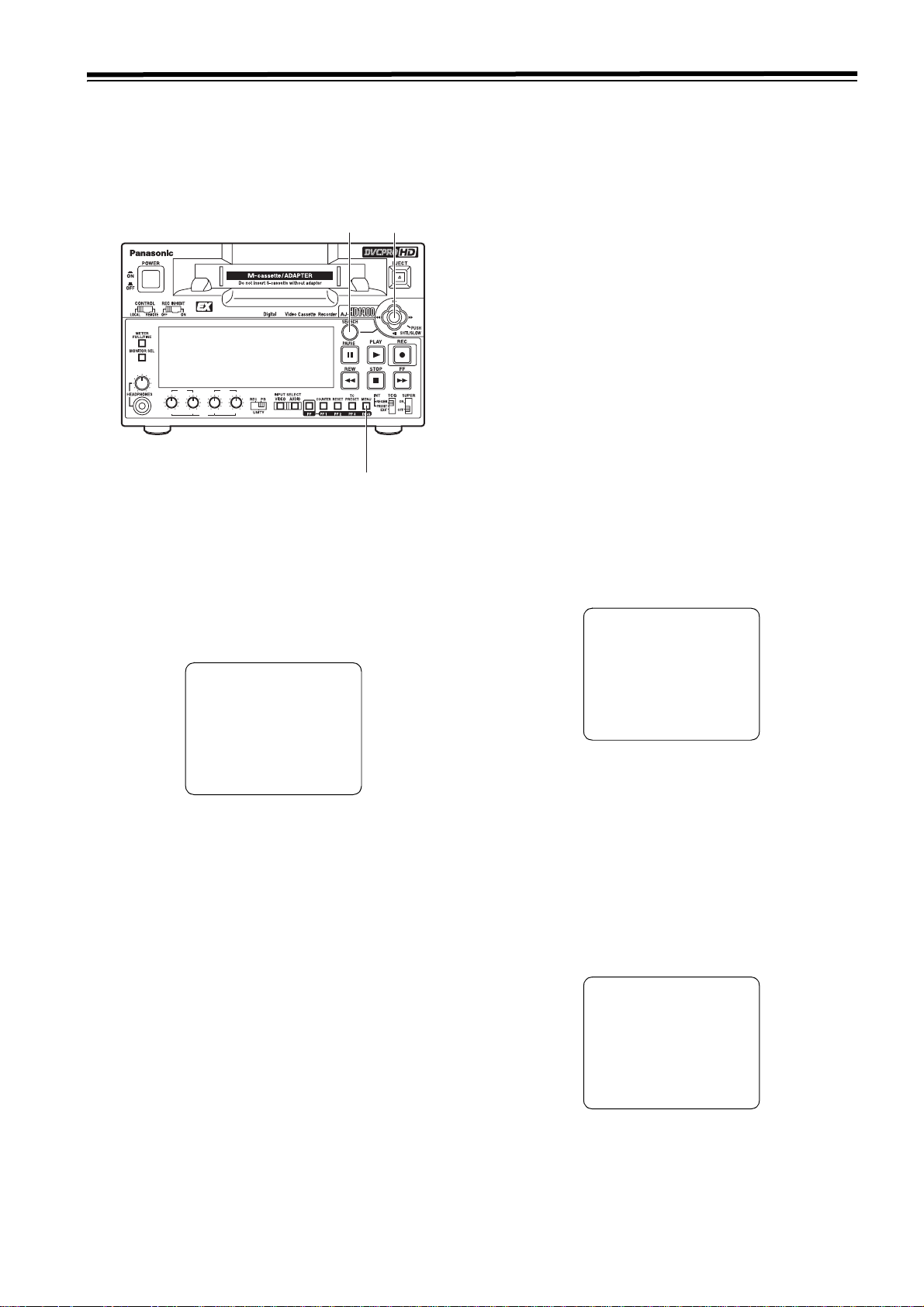
This unit’s main settings can be performed and checked using the on-screen menus which are displayed on the video monitor
connected to the unit.
It is also possible to set and confirm using the item number and the setting number or the item name, which are displayed on
the display part on the front panel.
Furthermore, a user setting memory in which to store three sets of settings is provided, enabling the desired settings to be
stored for future use.
5
2, 3, 4
HD
REC
CH3/7 CH4/8
PB
PB
CH1 CH2 CH1 CH2
CH1/5 CH2/6
1, 7
Setting method using the on-screen menus
1 Press the MENU button.
SETUP-MENU MAIN is displayed on the video monitor,
and the names of the main menu items are displayed in
the counter display.
5 Incline the joystick right and left while pressing the
SEARCH button at the changing position.
The set value on the settings screen and the set value in
the counter display flash; the value changes each time
the joystick is inclined right and left. When the set value
is displayed, return the joystick.
In order to return the set value to the factory settings,
press the RESET button while pressing the SEARCH
button.
6 To change the other items, repeat the process 4, 5, and
6.
7 Press the MENU button.
z When the set value is not changed, the display of the
menu screen disappears.
z When the set value is changed, a confirmation screen
will be displayed.
z Press the PLAY button to save the changes of the set
value.
z Press the STOP button to cancel the change of the set
value.
SETUP-MENU SE T OK?
YES<PLAY>/ NO<STOP>
SETUP-MENU MA IN
NO.00
¢
00 SYSTEM
000 BASIC
100 OPERAT ION
200 INTERF ACE
300 EDIT
400 TAPE P ROTECT
500 TIME C ODE
600 VIDEO
700 AUDIO
2 Incline the joystick up and down to select the main menu
item.
The cursor (¢) for the main menu items on the select
screen moves up and down and the names of main
menu items are displayed on the counter display.
3 Incline the joystick toward the right to move the cursor on
the settings screen to each item.
The settings screen for each item is displayed on the
video monitor, and the item number in the counter
display will flash. When the FF button is pressed for
about 1.5 seconds, the item name will be displayed in the
counter display. When the FF button is pressed for about
1.5 seconds again, the display returns to the item
number.
In order to return to the SETUP-MENU MAIN screen,
incline the joystick toward the left.
Returning to the factory settings
1 Press the MENU button.
A select screen for the major menu items is displayed on
the video monitor and the names of the major menu
items are displayed in the counter display.
2 Press the RESET button.
The unit is now set to the default setting mode, and the
default setting screen now appears on the video monitor.
SELECT MODE
¢ 0 ESCAPE
1 LO AD
2 SA VE
3 PR OTECT
4 Incline the joystick up and down to select the item to
change the setting.
The cursor (¢) on the select screen moves up and down,
and the item number flashes on the counter display.
27
Page 3

Setup (initial settings) (continued)
3 Incline the joystick up and down to adjust the cursor in
the default settings screen to the “LOAD” position and
press the joystick. The mode for this unit changes to the
LOAD mode, the LOAD screen is displayed on the video
monitor, and the item name is displayed in the counter
display.
SET-UP MENU <LOAD>
¢ NO
FACT ORY
USER 1(ALL)
USER 2(ALL)
USER 3(ALL)
USER 1(NOT SYSTE M)
USER 2(NOT SYSTE M)
USER 3(NOT SYSTE M)
4 Incline the joystick up and down to adjust the cursor in
the LOAD screen to the “FACTORY” position and press
the joystick.
z If this operation is made after moving the cursor to
“FACTORY,” values for all menus except the SYSTEM
menu will return to the factory settings.
z When the cursor is moved to “NO” and this operation is
performed, the display returns to the menu screen
without restoring the factory settings.
5 The confirmation screen is displayed on the video
monitor.
z When the PLAY button is pressed, the unit returns to
the factory settings and the display of the menu screen
disappears.
z When the STOP button is pressed, the display returns
to the menu screen without changing the settings.
SETUP-MENU < LOAD>
FACTORY OK?
YES<PLAY>/N O<STOP>
Setting the user defaults
1 Press the MENU button.
A select screen for major menu items is displayed on the
video monitor, and the names are displayed in the
counter display.
2 Follow the procedure described in “Setting method using
the on-screen menus” (page 27) 2–6 and adjust the
desired settings.
3 Press the RESET button.
The mode for this unit will change to the default setting
mode, and the default setting screen will be displayed on
the video monitor.
SELECT MODE
¢ 0 ESCAPE
1 LO AD
2 SA VE
3 PR OTECT
4 Incline the joystick up and down to adjust the cursor in
the default settings screen to the “SAVE” position and
press the joystick.
The mode for this unit changes to the SAVE mode, the
SAVE screen is displayed on the video monitor, and the
item name is displayed in the counter display.
SET-UP MENU <SAVE>
¢ NO
USER 1(ALL)
USER 2(ALL)
USER 3(ALL)
USER 1(NOT SYSTE M)
USER 2(NOT SYSTE M)
USER 3(NOT SYSTE M)
5 Incline the joystick up and down to adjust the cursor on
the SAVE screen to the “USER ¢ (ALL)” position (¢
each value from 1 to 3.) and press the joystick.
z When storing a set value other than SYSTEM menu in
memory, move the cursor to “USER ¢ (NOT
SYSTEM)” (¢ each value from 1 to 3.) and press the
joystick.
z To cancel the operation, move the cursor to “NO” and
press the joystick.
28
Page 4

Setup (initial settings) (continued)
6 Confirmation screen for SAVE is displayed.
z When the PLAY button is pressed, the set value is
stored and the display returns to the menu screen.
z When the STOP button is pressed, the display returns
to the menu screen without storing the set value.
SET-UP MENU <SAVE>
USER1(ALL) O K?
YES<PLAY>/N O<STOP>
7 When the MENU button is pressed, the display of the
menu screen disappears.
User default loading method
1 Press the MENU button.
A select screen for the major menu items is displayed on
the video monitor, and the names are displayed in the
counter display.
4 Incline the joystick up and down to adjust the cursor on
the LOAD screen to the “USER ¢ (ALL)” (¢ each value
from 1 to 3.) position and press the joystick.
z When loading a set value other than SYSTEM menu in
memory, move the cursor to “USER ¢ (NOT
SYSTEM)” (¢ each value from 1 to 3.) and press the
joystick.
z To cancel the operation, move the cursor to “NO” and
press the joystick.
5 LOAD confirmation will be displayed.
z When the PLAY button is pressed, the set value is
loaded and the display of the menu screen disappears.
z When the STOP button is pressed, the display returns
to the menu screen without loading the set value.
SET-UP MENU <LOAD>
USER1(ALL) O K?
YES<PLAY>/N O<STOP>
2 Press the RESET button.
The unit is now set to the default setting mode, and the
default setting screen now appears on the video monitor.
SELECT MODE
¢ 0 ESCAPE
1 LO AD
2 SA VE
3 PR OTECT
3 Incline the joystick up and down to adjust the cursor on
the default settings screen to the LOAD position and
press the joystick.
The mode for this unit changes to the LOAD mode, the
LOAD screen is displayed on the video monitor, and the
item name is displayed in the counter display.
SET-UP MENU <LOAD>
¢ NO
USER 1(ALL)
USER 2(ALL)
USER 3(ALL)
USER 1(NOT SYSTE M)
USER 2(NOT SYSTE M)
USER 3(NOT SYSTE M)
29
Page 5

Setup (initial settings) (continued)
Menu protection method
By switching to the menu protect mode, it is possible to
disable the setup menu even if the MENU button on the front
panel is pressed.
1 Press the MENU button.
A select screen for the major menu items is displayed on
the video monitor, and the names are displayed in the
counter display.
2 Press the RESET button.
The unit will switch to the default setting mode, and the
default screen will be displayed on the video monitor.
SELECT MODE
¢ 0 ESCAPE
1 LO AD
2 SA VE
3 PR OTECT
3 Tilt the joystick up/down to move the cursor to the
“PROTECT” position on the default screen and then
press the joystick.
The unit enters the menu protect setting mode, and the
confirmation screen is displayed on the video monitor.
Menu protection release method
1 Press the MENU button when pressing the COUNTER
button on the front panel.
A select screen for the major menu items is displayed on
the video monitor, and the names are displayed in the
counter display.
2 Execute the procedures from 2 to 3 described in the
“Menu protection method.”
The unit will be set to the menu protect setting mode, and
the display for confirming menu protection will appear on
the video monitor.
MENU PROTECT OK?
YES<PLAY>/N O<STOP>
3 Press the STOP button.
The menu is displayed.
4 Press the MENU button.
The menu disappears, and the menu protect mode is
released.
MENU PROTECT OK?
YES<PLAY>/N O<STOP>
4 Press the PLAY button.
The menu is displayed.
5 Press the MENU button.
The menu disappears and the unit will switch to the
menu protect mode.
z If the MENU button is pressed while the menu protect
mode is set, the message <MENU PROTECT> is
displayed on the video monitor and the menu is
displayed.
<Note>
To enable ordinary menu operation while the menu
protection mode is set, press the MENU button when
pressing the COUNTER button on the front panel.
30
Page 6
Setup (initial settings) (continued)
System frequency switching
<Selection of the record and playback format and the synchronizing signal depends on the operation mode>
NO.25
SYSTEM
FERQ
59/60
50i/25P
23/24 None
25 (HD) None 720/25p over 60p
25 (SD) None 720/25p over 60p
50 (HD) None 720/50p over 60p
50 (SD) None 720/50p over 60p
Recordable format Playback permissible format Synchronized signal
1080/59.94i (HD_LP)
720/59.94p (HD_LP)
720/60.00p (HD_LP)
(Only the variable frame rate
signal can be recorded.)
1080/50i (HD_LP)
720/50p (HD_LP)
1080/59.94i
1080/60i
720/59.94p
720/60.00p
480/59.94i (50M, 25M, DV, DVCAM)
1080/50i
720/50p
576/50i (50M, 25M, DV, DVCAM)
576/25p over 50i (50M, 25M, DV)
1080/23.98p over 59.94i [2:3 mode]
1080/23.98p over 59.94i [2:3:3:2 advance mode]
720/23.98p over 59.94p
720/24p over 60.00p
480/23.98p over 59.94i [2:3 mode]
480/23.98p over 59.94i [2:3:3:2 advance mode]
HD_REF (59.94Hz, 60Hz)
SD_REF (59.94Hz)
According to the setting in menu
No. 031 OUT REF.
HD_REF (50Hz)
SD_REF (50Hz)
According to the setting in menu
No. 031 OUT REF.
HD_REF (47.96Hz, 48Hz)
HD_REF (50Hz)
SD_REF (50Hz)
According to the setting in menu
No. 031 OUT REF.
HD_REF (50Hz)
SD_REF (50Hz)
According to the setting in menu
No. 031 OUT REF.
HD_REF (50Hz)
SD_REF (50Hz)
According to the setting in menu
No. 031 OUT REF.
HD_REF (50Hz)
SD_REF (50Hz)
According to the setting in menu
No. 031 OUT REF.
Procedure for shifting the system frequency
To shift the system frequency execute the following operations.
1 Change the set value of menu item No. 25 SYSTEM
FREQ. For the method to change the set value, refer to
"Setting method using the on-screen menus" (page 27) .
Once the set value is changed, the outer frame of the
display part of SYSTEM FREQ and the characters in
SYSTEM on the front display panel start flashing.
SYSTEM
59.94 60
50/25PsF
24
23.98
50
25
HD
SD
2 Press the MENU button.
3 The confirmation screen is displayed to enable the
changed set value.
SETUP-MENU SE T OK?
YES<PLAY>/N O<STOP>
S
ystem menu item No.
(SYSTEM FREQ)
has been changed.
z To enable the change to set value, press the PLAY
button. Then the system resumes and starts again in
the selected mode.
z To disable the change to the set value, press the STOP
button. Any other changes in the set up menu items
are also disabled.
<Note>
If the system is restarted when a cassette remains in the
unit, the cassette will automatically be ejected.
setting
25
31
Page 7
Setup menus
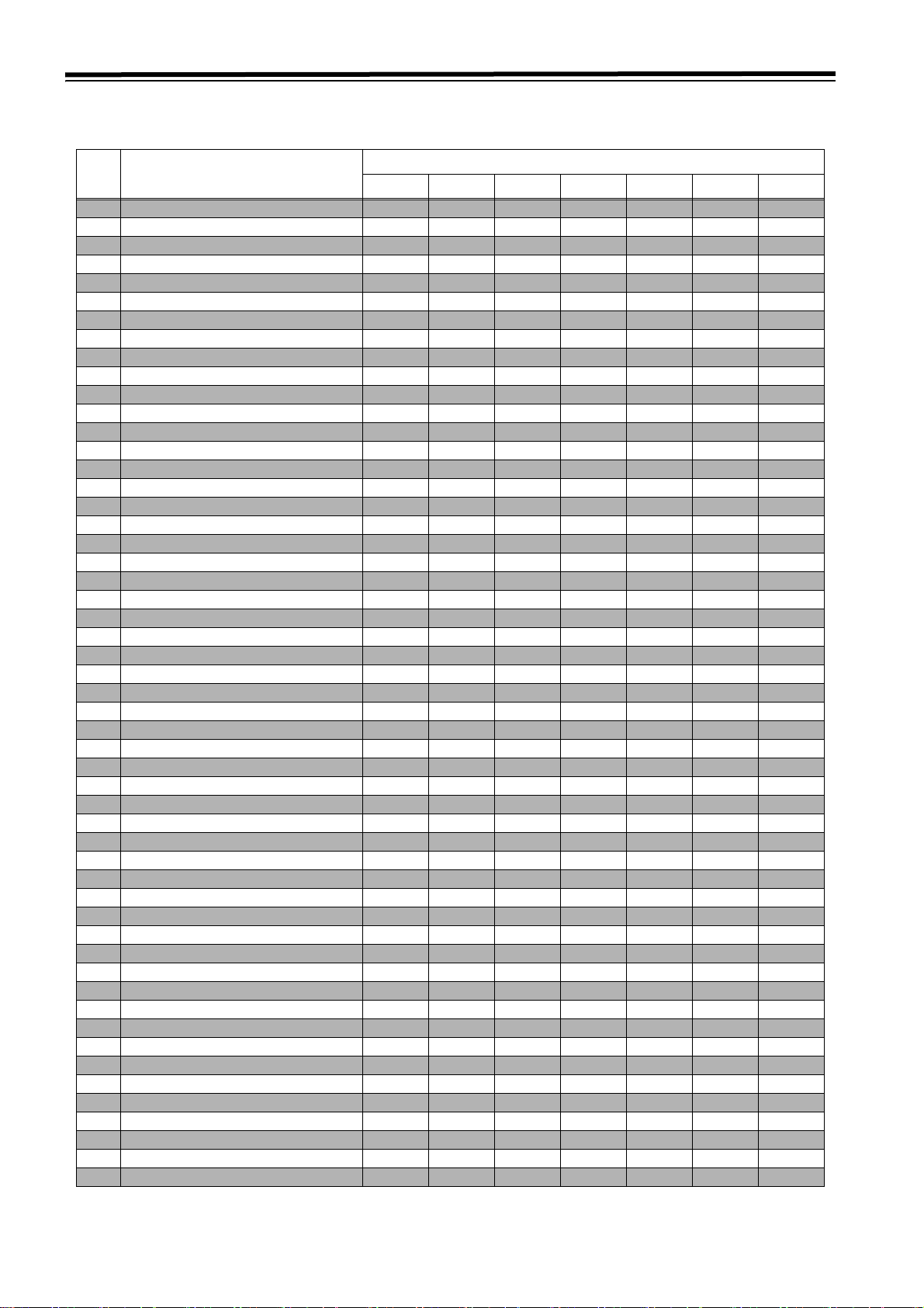
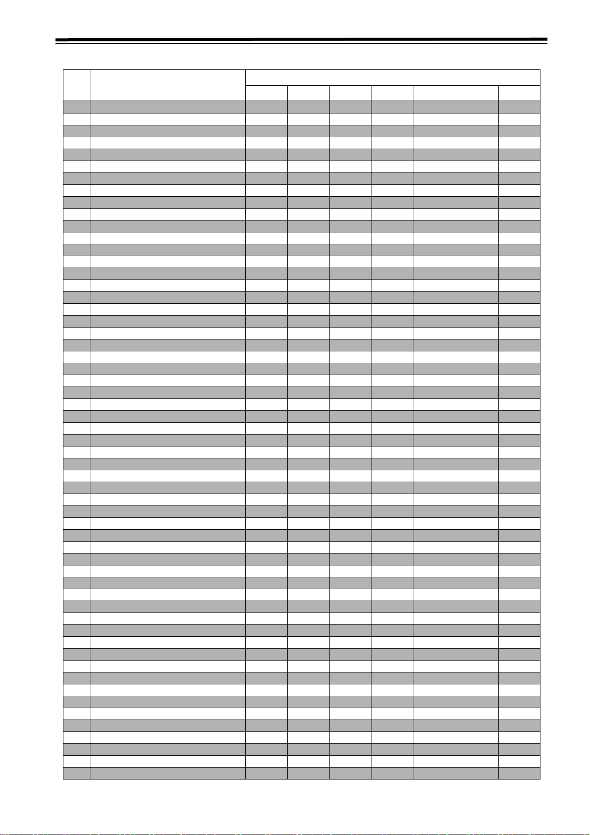
Menus which are displayed
The menus displayed differ depending on the setting selected for menu item No.25 SYSTEM FREQ.
NO. Item
59/60 23/24 50i/25P 25 (HD) 25 (SD) 50 (HD) 50 (SD)
05 ENCODER SEL
06 V LEVEL CTRL
12 SYS H (HD)
14 SYS SC (SD)
15 VO SYS H (SD)
16 SD SYS H (SD)
18 SCH COAR (SD)
19 SCH FINE (SD)
20 AV PHASE
25 SYSTEM FREQ
26 HD SYS H ADV No No No No No No
001 LOCAL ENA
002 TAP E TI ME R No No No No No
003 REMAIN SEL
005 SUPER
006 DISPLAY SEL
007 CHARA H-POS
008 CHARA V-POS
009 CHARA TYPE
020 SYS FORMAT No No No No No
022 PB FORMAT
023 FORMAT SEL
030 HD FREQUENCY No No No No No
031 OUT REF No
032 REC REF No No No No No No
100 SEARCH ENA
101 SHTL MAX
102 FF. REW MAX
104 REF ALARM
105AUTO EE SEL No NoNoNoNo
106 EJECT EE SEL
107 EE MODE SEL No No No No No
108 PLAY DELAY
109 CAP. LOCK No No No No No
110 AUTO REW
112 FRZ MODE SEL
114 REC INH LAMP
115 EJECT SW INH No No No No No
118 SP MODE INH No No No No No
119 CONFI REC No No No No No
134 ARARM BEEP
140 OUTPUT No No No No No
152 HUMID OPE
154 AUTO BACK No No No No No
155 AUTO REC No No No No No
160 MEMORY MODE
161 CTL BGN/TC BGN
162 END
163 REPT MODE
180 BATTERY SEL
181 TYPE-A NEAR
182 TYPE-A END
183 TYPE-B NEAR
Menu No.25 SYSTEM FREQ
32
Page 8
Setup menus (continued)
NO. Item
184 TYPE-B END
190 V IN SEL INH No No No No No
191 A IN SEL INH No No No No No
202 ID SEL
302 CONFI EDIT No No No No No
303 AUD EDIT IN No No No No No
304 AUD EDIT OUT No No No No No
307AFTER CUE-UP No NoNoNoNo
320 EDIT RPLCE1 No No No No No
321 EDIT RPLCE2 No No No No No
322 EDIT RPLCE3 No No No No No
323 EDIT RPLCE4 No No No No No
324 EDIT RPLCEC No No No No No
400 STILL TIMER
401 SRC PROTECT
402 DRUM STDBY
403 STOP PROTECT
500 VITC BLANK No No No
501 VITC POS-1 No No No
502 VITC POS-2 No No No
503 TCG MODE No No No No No
504 RUN MODE No No No No No
505 TCG REGEN No No No No No
506 REGEN MODE No No No No No
507 EXT TC SEL No No No No No
508 BINARY GP No No No No No
509 PHASE CORR
510 TCG CF FLAG No No No No No
511 DF MODE No No No No No No
512 TC OUT REF No No No No No
513 VITC OUT
514 HD EMBD VITC No No
515 HD EMBD LTC No No
601 VIDEO INT SG No No No No No
602 SDI IN MODE No No No No No
603 V-MUTE SEL
604 FREEZE SEL
615 V OUT SEL No No No No
619 V_FILTER No No No No No No
620 DOWNCON MODE No No
621 UPCONV MODE No No No No
626 D/C ENH H No No
627 D/C ENH V No No
628 U/C ENH H No No No No
629 U/C ENH V No No No No
630 1080i>HD_OUT No NoNoNoNo
632 720p>HD_OUT No No No No
636 SD>HD_OUT No NoNoNoNo
650 STYLE
651 HUE STYLE (SD) No No No No No
653 Y LVL (HD)
654 Pb LVL (HD)
655 Pr LVL (HD)
656 BK LVL (HD)
658 Y LVL (SD)
659 Pb LVL (SD)
660 Pr LVL (SD)
59/60 23/24 50i/25P 25 (HD) 25 (SD) 50 (HD) 50 (SD)
Menu No.25 SYSTEM FREQ
33
Page 9
Setup menus (continued)
NO. Item
661 BK LVL (SD)
662 V LEVEL
663 C LEVEL
664 HUE
665 SETUP LVL
676 BLK CLIP No No No No No
680 CC (F1) BLANK No No No No No No
681CC (F2) BLANK NoNoNoNoNoNo
682 VO SETUP (HD) (For AJ-HD1400P) No No No No No
683 VO SETUP (SD) (For AJ-HD1400P) No No No No No
684 EDH (SD) No No
685 ESR MODE (SD) No No No No No
686 CCR MODE (SD) No No No No No
687 SDI INDEX 0 No No No
689 COMP MODE No No No No No No
690 UMID REC No No No No No
691 UMID GEN No No No No No
692UMID POS No NoNoNoNo
693 GAMMA SEL
695 BLANK LINE No No No No No
701 CH1 IN LV No No No No No
702 CH2 IN LV No No No No No
706 CH1 OUT LV
707 CH2 OUT LV
710 MONIL OUT LV
711 MONIR OUT LV
712 MONI OUT
724 REC CH3/4 No No No No No
730 REC CUE No No No No No
731 PB FADE
732 EMBEDDED AUD
746 MONI CH SEL
750 ANA CH1/2 SEL
759DV PB ATT No NoNoNoNo
760 REC PT MUTE No No No No No
762 AUD RATE CON
765 CUE OUT SEL
781 IN IMP SEL No No No No No
782 EMB CH SEL
783 AUDIO CH SEL
784 MONI SEL INH
880 DIF SPEED No No No No No
882 DIF IN CH No No No No No
883 DIF OUT CH No No No No No
886 DIF CONFIG No No No No No
890 DIF AUD OUT No No No No No
891 DIF DV AUDIO No No No No No
892 DIF SIG CMD No No No No No
894 HD>DIF OUT No No No No No
895 50M>DIF OUT No NoNoNoNo
896 25M>DIF OUT No No No No No
899DIF SUPER No NoNoNoNo
A02 P. O N L OA D
A04 PF1 ASSIGN
A05 PF2 ASSIGN
A06 PF3 ASSIGN
59/60 23/24 50i/25P 25 (HD) 25 (SD) 50 (HD) 50 (SD)
Menu No.25 SYSTEM FREQ
34
Page 10

Setup menus (continued)
Video output signal adjustments
The control matrix for the adjustments is shown in the table
below.
This function is not available for IEEE1394 digital output.
When “CMPNT” has been selected as the menu item No.650
STYLE setting
Setting Adjustment item
05:
ENCODER
SEL
LOCAL
BOTH
06:
V LEVEL
CTRL
HD
BOTH
HD
SD AJ-HD1400
BOTH
653: Y LVL (HD)
654: Pb LVL (HD)
655: Pr LVL (HD)
656: BK LVL (HD)
AJ-HD1400 AJ-HD1400SD
External encoder
remote controller/
AJ-HD1400
External encoder
remote controller/
AJ-HD1400
658: Y LVL (SD)
659: Pb LVL (SD)
660: Pr LVL (SD)
661: BK LVL (SD)
AJ-HD1400
External encoder
remote controller/
AJ-HD1400
External encoder
remote controller/
AJ-HD1400
AJ-HD1400:
Only adjustments of the setup menu items are
performed.
External encoder remote controller/AJ-HD1400:
Adjustments can be performed from both the external
encoder remote controller and setup menus.
When “CMPST” has been selected as the menu item No.650
STYLE setting
Setting Adjustment item
05:
ENCODER SEL
LOCAL AJ-HD1400
BOTH
662: V LEVEL
663: C LEVEL
664: HUE
665: SETUP LVL
External encoder
remote controller
/AJ-HD1400
AJ-HD1400:
Only adjustments of the setup menu items are
performed.
External encoder remote controller/AJ-HD1400:
Adjustments can be performed from both the external
encoder remote controller and setup menus.
<Notes>
z Use the MT-200/2000 (manufactured by Musashi and
recommended by Panasonic) as the external encoder
remote controller. However, its VIDEO PHASE, SYNC
PHASE and SC PHASE controls will not work.
During menu operations and operations using the PF
function, operations from the external encoder remote
controller cannot be accepted.
z Both the HD and SD can be controlled at the same time
regardless of the setting of the menu No.06 V LEVEL
CTRL.
<Notes>
z Use the AJ-ER50 as the external encoder remote
controller. However, its “VIDEO PHASE” and “SYNC
PHASE” controls will not work.
z During menu operations and operations using the PF
function, operations from the external encoder remote
controller cannot be accepted.
35
Page 11

Setup menus (continued)
SYSTEM
No./Item Description of setting
05
ENCODER
SEL
06
V LEVEL
CTRL
12
SYS H
(HD)
14
SYS SC
(SD)
For setting whether to perform the various
adjustments for the video output signals using this
VTR or using an external encoder remote controller.
0001 LOCAL
The various adjustments for the video output
signals are performed using this VTR.
0002 BOTH :
The various adjustments for the video output
signals are performed using both this VTR and an
external encoder remote controller.
<Notes>
z For video adjustments, refer to “Video output signal
adjustments” (page 35).
z If the signals are adjusted with the external
encoder remote controller, the adjusted values are
reflected in the setup menu. However, the adjusted
numerical values will not be stored unless about 1
minute has elapsed after completion of the
adjustment operation. If the unit is turned off after
executing the adjustments with the external
encoder remote controller, it is necessary to wait
about 1 minute before turning off the power.
z Settings in this menu are not effective for the
IEEE1394 digital output.
For selecting what is to be controlled when the video
output level is to be adjusted by an external encoder
remote controller.
0000 HD :
The HD video output level can be adjusted.
0001 SD :
The SD video output level can be adjusted.
0002 BOTH :
Both the HD and SD video output levels can be
adjusted.
<Note>
When “CMPST” is selected in menu No. 650 STYLE,
the unit will be in the same state as when “BOTH” is
selected, regardless of the settings in this item.
For adjusting the system phase of the HD SDI output
signals. (in 13.5 ns increments).
– :Phase advances.
+ :Phase delays.
0000 –1100
: :
1100
: :
2200 1100
<Notes>
z When menu item No. 25 SYSTEM FREQ is set to
50i/25P, 25 (HD), 25(SD), 50 (HD) or 50 (SD), the
setting range is from –1320 - 0
z When menu item No. 25 SYSTEM FREQ is set to
23/24, the setting range is from –1375 - 0
For adjusting the system phase of the analog
composite output and SD SDI output signals (total
variable range of over ±180 degrees).
– :Phase advances.
+ :Phase delays.
0000 –108
: :
0108
: :
0216 108
:
0
0
- 1320.
- 1375.
No./Item Description of setting
15
VO SYS H
(SD)
16
SD SYS H
(SD)
18
SCH
COAR
(SD)
19
SCH FINE
(SD)
20
AV
PHASE
For adjusting the system phase of the analog
composite output signals (in 37 ns increments).
– :Phase advances.
+ :Phase delays.
0000 –858
: :
0858
: :
1716 858
<Note>
The setting range is –864 to 0 to 864 when 50i/25P,
25 (HD) or 25 (SD) is selected as the menu item
No.25 SYSTEM FREQ setting.
For adjusting the system phase of the SD SDI output
signals (in 37 ns increments).
– :Phase advances.
+ :Phase delays.
0000 –858
: :
0858
: :
1716 858
<Note>
The setting range is –864 to 0 to 864 when 50i/25P,
25 (HD) or 25 (SD) is selected as the menu item
No.25 SYSTEM FREQ setting.
For adjusting the SCH (sub-carrier to horizontal)
phase of the analog composite output signals (4
positions in 90-degree increments).
The SC phase changes, and the H phase remains
unchanged.
0000 0
0001 90
0002 180
0003 270
For adjusting the SCH (sub-carrier to horizontal)
phase of the analog composite output signals
(variable range of over ±45 degrees).
The SC phase changes, and the H phase remains
unchanged.
A range of ±180 degrees is covered by using this
setting in combination with item No.18 SCH COAR
(SD).
0000 –32
: :
0032
: :
0064 32
For adjusting the phase of the AUDIO output signals
in relation to the video output signals (in 20.8 µs
increments).
– :Audio phase against image advance.
+ :Audio phase against image delay.
0000 –100
: :
0100
: :
0200 100
0
0
0
0
“_____” indicates the factory setting.
36
Page 12

Setup menus (continued)
SYSTEM (continued)
No./Item Description of setting
25
SYSTEM
FREQ
1
26*
HD SYS H
ADV
*1 Displayed menus may vary depending on the settings in
menu No. 25 SYSTEM FREQ. For details, refer to
“Menus which are displayed” (page 32).
For selecting the system frequency.
For details, refer to “Procedure for shifting the system
frequency" (page 31).
0000 59/60
The 59.94 Hz or 60 Hz system frequency is
selected.
0001 50i/25P
The 50 Hz or 25 PsF system frequency is selected.
At this setting, the 1080/25 PsF format signals can
be recorded and played back in the same way as
with the 1080/50i format.
0002 23/24 :
The 23.98 Hz or 24 Hz system frequency is
selected.
0003 25(HD)
The 25 Hz system frequency is selected. However,
black signals are output from the SD SDI output
and analog composite connectors.
0004 25(SD) :
The 25 Hz system frequency is selected. However,
black signals are output from the HD SDI output
and analog component connectors.
0005 50(HD) :
The 50 Hz system frequency is selected. However,
black signals are output from the SD SDI output
and analog composite connectors.
0006 50(SD) :
The 50 Hz system frequency is selected. However,
black signals are output from the HD SDI output
and analog component connectors.
For selecting the output whose HD output phase is to
be advanced by 90H in relation to the SD output.
0000 0H
Both the HD and SD signals are output in phase
with the HD and SD REF output signals.
0001 90H :
The HD signals are output at a phase advanced by
90H from the SD output signals.
When the SD REF signal is input, the REF input
and SD output are in-phase, and when the HD REF
signal is input, the REF input and HD output are
inphase.
<Notes>
z The audio signals and TC signal are output in
phase with the HD output.
z With the 720p format, there is a phase difference of
120H between them.
:
:
:
:
BASIC
No./Item Description of setting
001
LOCAL
ENA
1
002*
TAPE T I ME R
003
REMAIN SEL
005
SUPER
For setting the operable buttons on the front panel
when the REMOTE/LOCAL switch is set to
“REMOTE.”
0000 DIS :
None of the buttons can be operated.
0001 ST&EJ :
Only the STOP and EJECT buttons can be
operated.
0002 ENA1 :
All of the buttons with the exception of COUNTER
and RESET can be operated.
0003 ENA2 :
All of the buttons can be operated.
For setting how the time is to be displayed on the CTL
counter display.
0000 ±12h :
12-hour display
0001 24h :
24-hour display
For setting the remaining time on the tape for the
respective connectors and the superimposed
indications of the total length of the tape.
0000 OFF :
No displays are superimposed.
0001 2L :
The remaining tape time is displayed on the
second line.
0002 1L :
The remaining tape time is displayed on the first
line.
0003 R/TTL :
The remaining tape time is displayed on the first
line and the total tape duration on the second line.
<Note>
The information will not be displayed when “2L” or “R/
TTL” is set and TIME is selected as the menu item
No.006 DISPLAY SEL setting.
For setting the superimposing of the displays onto
various connectors.
0000 OFF :
The displays are superimposed onto none of the
output connectors.
0001 CMPST :
The displays are superimposed onto the analog
composite output.
0002 CMPNT :
The displays are superimposed onto the HD
analog component output.
0003 SDSDI :
The displays are superimposed onto SD SDI OUT.
0004 HDSDI :
The displays are superimposed onto HD SDI OUT.
0005 CPS&SD :
The displays are superimposed onto the analog
composite output and SD SDI OUT.
0006 CPN&HD :
The displays are superimposed onto the HD
analog component output and HD SDI OUT.
<Notes>
z The information will not be displayed when the
SUPER switch is OFF.
z 1394 output is according to Menu No. 899 DIF
SUPER.
z If the 23.98/24 Hz, 25 Hz (HD), or 50 Hz (HD)
mode is selected in menu No. 25 SYSTEM FREQ,
no super is displayed on the analog composite
output and the SD SDI output.
If the 25 Hz (SD) or 50 Hz (SD) mode is selected,
no super is displayed on the analog component
output and the HD SDI output.
“_____” indicates the factory setting.
37
Page 13

Setup menus (continued)
BASIC (continued)
No./Item Description of setting
006
DISPLAY
SEL
007
CHARA
H-POS
008
CHARA
V-PO S
For setting what the information to be superimposed.
0000 TIME :
Only the data is displayed.
(“Data” refers to the CTL, TC or UB value selected
by the COUNTER button.)
0001 T&STA :
The data and operation status are displayed.
0002 T&S&M :
The data, operation status and mode are
displayed.
0003 T&RT :
The data and REC TIME are displayed.
0004 T&YMD :
The data and REC DATE (year/month/day) are
displayed.
0005 T&MDY :
The data and REC DATE (month/day/year) are
displayed.
0006 T&DMY :
The data and REC DATE (day/month/year) are
displayed.
0007 T&UB :
The data and user bits are displayed. The time
code is displayed after the user bits when the
COUNTER button is set to UB.
0008 T&CTL :
The data and CTL are displayed. The time code is
displayed after the CTL data when the COUNTER
button is set to CTL.
0009 T&T :
The data and time code are displayed.
<Notes>
z Depending on the format used, the following
displays appear for the modes.
<Format>
DVCPRO HD-LP
DVC P RO HD
DVC PRO5 0
DVC PRO
DV
DVC AM
z When T&S&M is selected as the item setting, an
error message is superimposed onto the display
when a warning or error occurs.
z REC TIME and REC DATE are displayed only
during DV or DVCAM playback. The operation
mode is displayed with the DVCPRO HD-LP,
DVCPRO HD, DVCPRO50 or DVCPRO format.
For setting the horizontal position at which the
superimposed characters are to be displayed.
0000 0
: :
0006
: :
0037 37
<Note>
Press the joystick and tilt up/down and right/left to set
the character position.
For setting the vertical position at which the
superimposed characters are to be displayed.
0000 0
: :
0023
: :
0032 32
<Note>
Press the joystick and tilt up/down and right/left to set
the character position.
23
>
<Display>
>
DVCPRO_HD-LP
>
DVC PRO_ HD
>
DVCPRO_50
>
DVC PRO
>
DV
>
DVC AM
6
No./Item Description of setting
009
CHARA
TYPE
1
020*
SYS FORMAT
022
PB FORMAT
023
FORMAT SEL
For setting the superimposed display and menu
display type.
0000 WHITE
White characters are displayed on a black
background.
0001 W/OUT :
White characters with black edges are displayed.
For setting the format in which to record or play back
the signals including the HD REF signals.
0000 1080i
1080i mode
0001 720p :
720p mode
For setting the format in which to play back the tape.
0000 MANUAL
The tape is played back in the format selected by
the menu item No.020 SYS FORMAT and No.023
FORMAT SEL setting.
0001 AUTO :
The tape is played back in the format selected by
the format in which the tape was recorded.
For selecting the format when “MANUAL” is selected
as the menu item No.022 PB FORMAT setting.
0000 HD_LP :
The DVCPRO HD-LP format is selected, and the
format follows the menu item No.020 SYS
FORMAT setting.
0001 HD_SP :
The DVCPRO HD format is selected, and the
format follows the menu item No.020 SYS
FORMAT setting.
0002 422 :
The DVCPRO50 (422) format is selected.
0003 411 :
The DVCPRO (411) format is selected.
0004 DV :
The DV format is selected.
0005 DVCAM :
The DVCAM format is selected.
:
:
:
*1 Displayed menus may vary depending on the settings in
menu No. 25 SYSTEM FREQ. For details, refer to
“Menus which are displayed” (page 32).
<Note>
When the signal format to be output is set to other than
DVCPRO HD and an external device is connected to the DV
connector, the following settings are recommended.
z Menu No. 022 PB FORMAT:
MANUAL
z Menu No. 023 FORMAT SEL:
Format of the tape that is inserted in the unit
“_____” indicates the factory setting.
38
Page 14

Setup menus (continued)
BASIC (continued)
No./Item Description of setting
1
030*
HD
FREQUENCY
1
031*
OUT REF
1
032*
REC REF
For setting the field frequency.
0000 59/23 :
The field frequency is set to 59.94/23.98 Hz.
0001 60/24 :
The field frequency is set to 60/24 Hz.
<Note>
The field frequency which is set here takes effect only
when there is no input which supports the OUT REF
setting.
If there is an input which supports the setting, the
field frequency is consistent with the field frequency
of input.
For selecting the video output reference.
0000 AUTO :
The REF signal (HD/SD) which is input to the REF
connector is automatically identified and serves as
the reference.
If no signal is supplied to the REF connector, the
HD serial input signal serves as the reference.
If neither the REF input signal nor HD serial input
signal is supplied, the unit’s internal reference is
used.
0001 INPUT :
The input signal serves as the reference.
If this signal is not available, the unit’s internal
reference is used.
0002 HD REF :
The HD REF input signal serves as the reference.
If this signal is not available, the unit’s internal
reference is used.
0003 SD REF :
The SD REF input signal serves as the reference.
If this signal is not available, the unit’s internal
reference is used.
0004 E-AUTO :
When the editing mode is selected, the state is the
same as when set to “INPUT.”
When any mode other than the editing mode is
selected, the state is the same as when set to
“AUTO.”
For details, refer to “Reference signals” (page 16).
Select the reference to synchronize the image frames
for recording.
0000 NORMAL
The video signal which is input is automatically
identified and serves as the reference.
0001 SLTC :
The time code which is input to the HD SDI IN
connector isidentified and serves as the reference.
<Note>
When the SLTC is selected, the following settings are
necessary to validate the settings for this item.
z Menu No. 25 SYSTEM FREQ: 59/60
z Menu No. 020 SYS FORMAT: 720p
z INPUT SELECT button on the front panel: HDSDI
:
Formats for playback
Depending on how the menu item No.020 SYS FORMAT,
No.022 PB FORMAT and No.023 FORMAL SEL settings are
combined, the formats of the tapes played back by the unit
differ as shown in the table below.
022.
PB FORMAT
MANUAL
AUTO
<Notes>
z When the tape is ejected, the format follows the one
selected by menu item No.020 SYS FORMAT setting.
z DVCPRO P playback is not possible.
020.
SYS FORMAT
1080i
720P
If AUTO is selected as the
menu item No.022 PB
FORMAT setting, the
format applying when the
format is not yet detected
(when the tape inserted)
follows the menu item
No.023 FORMAL SEL
setting.
However, if “DV” or
“DVCAM” is selected,
operation proceeds as if
“HD_LP” is selected.
023.
FORMAT SEL
HD_LP
HD_SP
50M
25M
DV
DVCAM
HD_LP
HD_SP
50M
25M
DV
DVCAM
Playback format
DVCPRO HD-LP (1080i)
DVCPRO HD (1080i)
DVCPRO50 (422)
DVCPRO (411)
DV
DVCAM
DVCPRO HD-LP (720p)
DVCPRO HD (720p)
DVCPRO50 (422)
DVCPRO (411)
DV
DVCAM
DVCPRO HD-LP
(1080i/720p),
DVCPRO HD (1080i/
720p), DVCPRO50
(422), DVCPRO (411),
DVCPROP (420p), DC
or DVCAM format is
detected automatically.
*1 Displayed menus may vary depending on the settings in
menu No. 25 SYSTEM FREQ. For details, refer to
“Menus which are displayed” (page 32).
“_____” indicates the factory setting.
39
Page 15

Setup menus (continued)
OPERATION
No./Item Description of setting
100
SEARCH
ENA
101
SHTL MAX
102
FF.REW MAX
104
REF ALARM
1
105*
AUTO E E
SEL
106
EJECT EE
SEL
To set the transition method to search mode (stick
operation).
0000 STICK :
Shift to the search mode when the SEARCH button
is pressed or when the stick is operated.
0001 KEY :
Do not shift to the search mode unless the
SEARCH button is pressed.
For setting the maximum speed in the shuttle mode.
0000 X8.4 :
8.4k normal speed
0001 X16 :
16k normal speed
0002 X32 :
32k normal speed
<Note>
The maximum speed for the HD SP mode is
automatically limited to 25k normal speed.
For setting the maximum speed of fast forward or
rewind operations.
0000 X16 :
16k normal speed
0001 X32 :
32k normal speed
0002 X50 :
50k normal speed
<Notes>
z The maximum speed for the HD SP mode is
automatically limited to 25k normal speed.
z The maximum speed for the DV and DVCAM
modes is automatically limited to 32k normal
speed.
For setting whether a warning is to be displayed when
the REF VIDEO signal is not connected.
0000 OFF :
No warning is displayed.
0001 ON :
A warning is displayed by the flashing STOP lamp.
For setting the mode of the VTR, which becomes the
EE state when menu item No. 140 OUTPUT is set to
“EE.”
0000 S/F/R :
The mode changes to the EE state when this item
is set to STOP, FF, or REW.
0001 STOP :
The mode changes to the EE state only when this
is set to STOP.
For setting the output conditions of video images and
voice when ejecting the tape.
0000 EE :
Both the video and audio signals are always output
in the EE (electric modulation to electric playback)
mode regardless of the setting of the menu No.140
OUTPUT.
0001 BLACK :
The output status differs according to the setting of
the menu No.140 OUTPUT.
EE: The signals are output in the EE mode.
TAPE: BLACK is output for the video, and the
audio is muted.
0002 GRAY :
The output status differs according to the setting of
the menu No.140 OUTPUT.
EE: The signals are output in the EE mode.
TAPE: GRAY is output for the video, and the audio
is muted.
<Note>
When “23/24” mode, “25 (HD/SD)” mode, or “50 (HD/
SD)” mode is selected in menu No. 25 SYSTEM
FREQ, BLACK is output if “EE” is selected.
No./Item Description of setting
1
107*
EE MODE
SEL
108
PLAY DELAY
1
109*
CAP. LOCK
110
AUTO R E W
112
FRZ MODE
SEL
114
REC INH
LAMP
For setting the HD SDI and HD analog component
output signals in EE mode when HD SDI input is
selected.
0000 NORMAL :
Signals delayed by the time taken by internal signal
processing are output.
0001 THRU :
Signal processing is not undertaken internally, and
the signals are output without delay at their original
timing.
<Notes>
z The superimposed information is not displayed
when THRU is used as the setting.
z When 1394 or SG is selected for the input signal in
edit mode, internal signal is selected forcibly
“NORMAL”.
For setting the play rise time in frame increments.
0000 0
: :
0015 15
For selecting in how many field increments the
playback framing is to be locked.
0000 2F
0001 4F
0002 8F
<Notes>
z “8F” can be selected only when “50i/25p” is
selected as the menu item No.25 SYSTEM FREQ
setting.
z In the HD LP or HD SP mode, 2F mode is selected
when recording and playing back, including editing,
regardless of the menu.
For setting whether the tape is to be automatically
rewound to its beginning when the tape end is detected.
0000 OFF :
The tape is not rewound.
0001 ON :
The tape is rewound to its beginning.
For setting the video output when the mode is
transferred from playback images to standby OFF
(half loading) mode or EJECT mode.
0000 DIS :
The video output is muted.
0001 STBOFF :
When the standby OFF (half loading) mode is
established, the image played back at that moment
is frozen and output.
0002 SOF&EJ :
When in the STANDBY OFF mode and the EJECT
mode, the image played back at that moment is
frozen and output.
<Notes>
z The frozen status will be according to the settings
in menu No. 604 FREEZE SEL.
z In the EJECT mode, the frozen image will be
output only when setup No. 106 EJECT EE is the 1
(BLACK) or 2 (GRAY) setting.
For setting the operation of the REC INHIBIT lamp when
the cassette is set to the erasure prevention status.
0000 LIGHT :
The lamp lights.
0001 FLASH :
The lamp flashes.
<Note>
When the REC INHIBIT switch on the front panel is set
to ON, the REC INHIBIT lamp lights at all times
regardless of what setting is selected for this menu item.
*1 Displayed menus may vary depending on the settings in
menu No. 25 SYSTEM FREQ. For details, refer to
“Menus which are displayed” (page 32).
40
“_____” indicates the factory setting.
Page 16

Setup menus (continued)
OPERATION (continued)
No./Item Description of setting
1
115*
EJECT SW
INH
1
118*
SP MODE
INH
1
119*
CONFI REC
134
ALARM
BEEP
1
140*
OUTPUT
For setting whether to restrict the operation of the
EJECT button on the front panel.
0000 REC :
Operation is inhibited while the unit is in the
recording mode.
0001 OFF :
The EJECT button can be operated in all operation
modes.
For selecting whether to enable or disable recording
on a tape which has been recorded using a format
other than DVCPRO HD-LP.
0000 OFF :
Recording onto the cassette tape is enabled.
0001 ON :
Recording onto the cassette tape is disabled.
For selecting whether or not to perform simultaneous
playback during normal recording (Other than the
frame-by-frame shooting).
0000 OFF :
The output for simultaneous playback during
normal recoding is switched in accordance with the
menu item No.140 OUTPUT.
EE: EE output
TAPE: Simultaneous playback output
0001 ON :
Simultaneous playback during normal recoding is
performed at all times, regardless of the setting of
the menu item No.140 OUTPUT.
For selecting the alarm sound for condensation,
termination of the tape (remaining time of about 2
minutes) or running out of battery power.
0000 OFF :
The alarm sound is not activated.
0001 ON :
The alarm sound is activated.
<Note>
If "ON" is selected in menu item No. 152 HUMID
OPE, the alarm sound for condensation is not
activated even if "ON" is selected.
For selecting the output signals.
0000 EE :
<In the STOP mode>:
The input signals selected by the setting of the
INPUT SELECT button are output.
<During recording or editing>:
The input signals selected by the setting of the
INPUT SELECT button are output:
0001 TAPE :
<In the STOP mode>
The signals played back from the tape are output.
<During recording or editing>:
The simultaneous playback signals are output.
<Note>
In order to select the output signals during recording
or editing, set menu item No.119 CONFI REC or
No.302 CONFI EDIT.
No./Item Description of setting
152
HUMID OPE
1
154*
AUTO BACK
For setting the unit’s operation when condensation
has formed.
0000 OFF :
The unit does not operate when condensation has
formed.
0001 ON :
It operates even when condensation has formed
but no guarantees are made that the operation will
be trouble-free.
<Note>
Since operating the unit when condensation has
formed may damage the tape or give rise to other
trouble, the “OFF” setting is recommended under
normal circumstances.
For setting how the follow-on recording function is to
be used.
(For setting the AUTO BACK function operation which
rewinds the tape for several seconds in order to
ensure that the video images follow on one from
another with no disruptions.)
0000 OFF :
The tape is not rewound automatically (no AUTO
BACK).
0001 REC-P :
The tape is rewound (AUTO BACK) during REC
PAUSE, and it then stops in the recording standby
status. (When PAUSE is released, the tape runs
up, and recording starts.)
0002 ALL :
In addition to the function of the 0001 REC-P
setting, the tape is rewound (AUTO BACK) during
REC PLAY, the tape immediately runs up, and
recording starts.
*1 Displayed menus may vary depending on the settings in
menu No. 25 SYSTEM FREQ. For details, refer to
“Menus which are displayed” (page 32).
“_____” indicates the factory setting.
41
Page 17

Setup menus (continued)
OPERATION (continued)
No./Item Description of setting
1
155*
AUTO R E C
For setting whether the recording/stop is executed
automatically in conjunction with the Recording Mark
of the HD SDI input signals from our camera recorder
or not.
0000 OFF :
Do not to execute the recording/stop automatically.
0001 TYPE1 :
To execute the recording/stop automatically in
conjunction with the Recording Mark in the LTC
information added to the HD SDI.
0002 TYPE2 :
To execute the recording/stop automatically in
conjunction with the Recording Mark in the SVITC
information added to the HD SDI.
<Notes>
z Set the LOCAL/REMOTE switch to the REMOTE
position.
z For the selection of TYPE 1 or TYPE 2, refer to
“Our camera recorder, Recording format, and
Recording Mark.”
z To select TYPE 1 or TYPE 2 to start recording
automatically, set this unit to the REC PAUSE
mode. It may not operate in any mode other than
the REC PAUSE mode. After accepting the auto
stop, this unit changes to the REC PAUSE mode.
z When this unit is recording in normal operation, the
AUTO REC function is not available.
*1 Displayed menus may vary depending on the settings in
menu No. 25 SYSTEM FREQ. For details, refer to
“Menus which are displayed” (page 32).
Our camera recorder, Recording format, and Recording Mark
Model Recording format
AJ-HDC27F, H 720/¢¢p over 60p
AJ-HDX400 1080/59.94i
AJ-HDX400E
AJ-HDX900
1080/50i
1080/25p over 50i
720/59.94p
720/23.98p over 59.94p
720/29.97p over 59.94p
1080/59.94i
1080/23.98p over 59.94i
1080/29.97p over 59.94i
1080/50i
1080/25p over 50i
720/50p
720/25p over 50p
Recording
Mark TYPE
TYPE1
2
–*
2
–*
2
–*
TYPE1
TYPE1
TYPE1
2
–*
TYPE2
2
–*
2
–*
2
–*
TYPE1
TYPE1
Remarks
ー
It is possible to
switch between
TYPE 1 and
TYPE 2. TYPE-1
and TYPE-2 are
the initial
settings for the
camera recorder.
If the unit is used
with the TYPE-1
settings, set the
UB MODE of the
camera to “FRM
RATE”. If it is
used with the
TYPE-2 settings,
set the VITC UB
MODE to “FRM
RATE.”
*2 In the initial settings, the Recording Mark is not
overlapped on the HD SDI signals.
No./Item Description of setting
160
MEMORY
MODE
161
CTL BGN
or
TC BGN
162
END
163
REPT MODE
180
BATTERY
SEL
For setting the repeat playback mode.
0000 OFF :
No repeat playback (normal operation).
0001 M-STOP :
The tape stops near the BEGIN point when it is fast
forwarded or rewound.
0002 REPT1 :
When the tape reaches the END point, it is
rewound to the BEGIN point, and stops.
0003 CONT :
When the tape reaches the END point, it is
rewound to the BEGIN point, and plays back, and
this is done repeatedly.
For setting the BEGIN point in the repeat playback
mode.
Either TC or CTL is set as the counter display mode
using the COUNTER button.
If no mode is set, – – : – – : – – : – – appears, and the
tape start serves as the BEGIN point.
For setting the END point in the repeat playback mode.
Either TC or CTL is set as the counter display mode
using the COUNTER button.
If no mode is set, – – : – – : – – : – – appears, and the
tape end serves as the END point.
For setting what images are to be output while the
tape returns to the BEGIN point in the repeat
playback mode.
0000 FREEZE :
The tape returns to the BEGIN point with the image
played back at the END point still frozen.
0001 BLACK :
The tape returns to the BEGIN point while the
screen remains black.
0002 MENU :
The tape returns to the BEGIN point following the
the settings in menu No. 140 OUTPUT.
<Note>
If the tape end is set as the END point when
“FREEZE” is selected, the playback image will not be
frozen properly.
Set the END point to a place within the range where
images are recorded.
For setting the type of battery.
0000 NiCd12 :
Settings for 1 pc. 12 V battery (NEAR: 11.2 V,
END: 10.6 V)
0001 NiCd13 :
Settings for 1 pc. 13 V battery (NEAR: 12.0 V,
END: 10.6 V)
0002 NiCd14 :
Settings for 1 pc. 14 V battery (NEAR: 13.6 V,
END: 10.6 V)
0003 S-LION :
Settings for 1 pc. lithium-ion battery “BP-L90A”.
(NEAR: 11.7 V, END: 10.6 V)
0004 I-LION :
Settings for 1 pc. lithium-ion battery “ENDURA80”.
(NEAR: 12.9 V, END: 12.4 V)
0005 TYPE-A :
Setting for using the battery selected by the menu
item No.181 TYPE-A NEAR item and No.182
TYPE-A END item
0006 TYPE-B :
Setting for using the battery selected by the menu
item No.183 TYPE-B NEAR item and No.184
TYPE-B END item
42
“_____” indicates the factory setting.
Page 18

Setup menus (continued)
OPERATION (continued)
No./Item Description of setting
1
181*
TYPE-A
NEAR
1
182*
TYPE-A END
1
183*
TYPE-B
NEAR
1
184*
TYPE-B END
2
190*
V IN SEL INH
For setting (in increments of 0.1 V) the voltage level at
which the counter flashes as warning for TYPE-A
battery (selected as the menu item No.180 BATTERY
SEL item).
Use when adjusting the settings for multiple batteries
or new type batteries.
0000 10.6
: :
0023
: :
0044 15.0
<Note>
When this item has been set to a voltage level close
to 15.0 V, the counter display may flash even when an
AC power source is being used.
For setting (in increments of 0.1 V) the voltage level at
which the TYPE-A battery (selected as the menu item
No.180 BATTERY SEL item) is to be automatically
turned off.
Use when adjusting the settings for multiple batteries
or new type batteries.
0000 10.6
: :
0018
: :
0034 14.0
For setting (in increments of 0.1 V) the voltage level at
which the counter flashes as warning for TYPE-B
battery (selected as the menu item No.180 BATTERY
SEL item).
Use when adjusting the settings for multiple batteries
or new type batteries.
0000 10.6
: :
0023
: :
0044 15.0
<Note>
When this item has been set to a voltage level close
to 15.0 V, the counter display may flash even when an
AC power source is being used.
For setting (in increments of 0.1 V) the voltage level at
which the TYPE-B battery (selected as the menu item
No.180 BATTERY SEL item) is to be automatically
turned off.
0000 10.6
: :
0018
: :
0034 14.0
For selection of the video input switching mode with
the INPUT SELECT switch.
0000 OFF :
Video input switching with the INPUT SELECT
switch is enabled.
0001 ON :
Video input switching with the INPUT SELECT
switch is prohibited.
0002 REC :
After this unit shifts to recording (except editing),
video input switching with the INPUT SELECT
switch is prohibited.
12.9
12.4
12.9
12.4
No./Item Description of setting
2
191*
A IN SEL INH
Select the audio input switching mode with the INPUT
SELECT switch.
0000 OFF :
Select the audio input switching mode with the
INPUT SELECT switch.
0001 ON :
Video input switching with the INPUT SELECT
switch is prohibited.
0002 REC :
After this unit shifts to recording (except editing),
video input switching with the INPUT SELECT
switch is prohibited.
*1 Even if the RESET button is pressed while pressing the
SEARCH button, the value may not return to the factory
setting.
*2 Displayed menus may vary depending on the settings in
menu No. 25 SYSTEM FREQ. For details, refer to
“Menus which are displayed” (page 32).
INTERFACE
No./Item Description of setting
202
ID SEL
“_____” indicates the factory setting.
For setting the ID information to be returned to the
controller.
0000 OTHER :
The ID information of the VTR other than DVCPRO
is set.
0001 DVCPRO :
The DVCPRO ID information is set.
0002 ORIG :
Set this only when the unit is connected to a
Panasonic controller (such as the AG-A850,
optional accessory).
<Note>
Select 1 (DVCPRO) or 2 (ORIG) if “23/24,” “25(HD),”
“25(SD),” “50(HD)” or “50(SD)” is selected as the
menu item No.25 SYSTEM FREQ setting.
43
Page 19

Setup menus (continued)
EDIT
No./Item Description of setting
1
302*
CONFI EDIT
1
303*
AUD EDIT IN
1
304*
AUD EDIT
OUT
1
307*
AFTER CUEUP
1
320*
EDIT
RPLCE1
1
321*
EDIT
RPLCE2
1
322*
EDIT
RPLCE3
For selecting whether to perform simultaneous
playback during editing.
0000 OFF :
Simultaneous playback is not performed.
0001 ON :
Simultaneous playback is performed.
For selecting how to connect the digital audio edit IN
points.
0000 CUT :
Cut processing
0001 FADE :
V-fade processing
For selecting how to connect the digital audio edit
OUT points.
0000 CUT :
Cut processing
0001 FADE :
V-fade processing
For selecting the VTR’s mode upon completion of the
cue-up operation.
0000 STOP :
The VTR is set to the STOP mode.
0001 STILL :
The VTR is set to the still picture (SHTL STILL)
mode.
0002 STILL2 :
The VTR is set to the still picture (VAR STILL)
mode.
For setting the allocation of the channels for the
analog audio presets of a controller when a controller
without a function to control the edit presets of the
digital audio signals is used to edit the digital audio
signals of the VTR.
The VTR’s CH1 edit presets are set to ON or OFF
following the analog audio signals specified by the
controller.
0000 N-DEF :
Not set.
0001 CH1 :
The analog CH1 edit presets are followed.
0002 CH2 :
The analog CH2 edit presets are followed.
0003 CH1+2 :
The analog CH1 or CH2 edit presets are followed.
As with menu item No.320, the VTR’s CH2 edit
presets are set to ON or OFF following the analog
audio signals specified by the controller.
0000 N-DEF :
Not set.
0001 CH1 :
The analog CH1 edit presets are followed.
0002 CH2 :
The analog CH2 edit presets are followed.
0003 CH1+2 :
The analog CH1 or CH2 edit presets are followed.
As with menu item No.320, the VTR’s CH3 edit
presets are set to ON or OFF following the analog
audio signals specified by the controller.
0000 N-DEF :
Not set.
0001 CH1 :
The analog CH1 edit presets are followed.
0002 CH2 :
The analog CH2 edit presets are followed.
0003 CH1+2 :
The analog CH1 or CH2 edit presets are followed.
No./Item Description of setting
1
323*
EDIT
RPLCE4
1
324*
EDIT
RPLCEC
As with menu item No.320, the VTR’s CH4 edit
presets are set to ON or OFF following the analog
audio signals specified by the controller.
0000 N-DEF :
Not set.
0001 CH1 :
The analog CH1 edit presets are followed.
0002 CH2 :
The analog CH2 edit presets are followed.
0003 CH1+2 :
The analog CH1 or CH2 edit presets are followed.
As with menu item No.320, the VTR’s CUE edit
presets are set to ON or OFF following the analog
audio signals specified by the controller.
0000 N-DEF :
Not set.
0001 CH1 :
The analog CH1 edit presets are followed.
0002 CH2 :
The analog CH2 edit presets are followed.
0003 CH1+2 :
The analog CH1 or CH2 edit presets are followed.
*1 Displayed menus may vary depending on the settings in
menu No. 25 SYSTEM FREQ. For details, refer to
“Menus which are displayed” (page 32).
“_____” indicates the factory setting.
44
Page 20

Setup menus (continued)
TAPE PROTECT
No./Item Description of setting
400
STILL TIMER
401
SRC
PROTECT
402
DRUM
STDBY
403
STOP
PROTECT
“_____” indicates the factory setting.
For setting the time to be taken before the unit is set
in the tape protection mode when it is left standing in
the STOP or STILL status.
(Units: S = seconds, min = minutes)
0000 0.5S
0001 5S
0002 10S
0003 20S
0004 30S
0005 40S
0006 50S
0007 1min
0008
<Note>
When a DV, DVCAM or an unused tape is used, or a
DVCPRO HD/DVCPRO50/DVCPRO tape is used in
the EE mode, any setting above 2 (10S) will result in
a setting time of 10 seconds.
For setting the operation to be performed in the tape
protection mode when the unit is left standing in the
STILL status (JOG/VAR/SHTL).
0000 STEP :
STEP FWD
0001 HALF :
STANDBY OFF (HALF LOADING)
<Note>
When STEP FWD is selected, the unit is
automatically transferred to the standby OFF (half
loading) mode when the unit is left standing in the
STOP mode for a total of 30 minutes (or 1 minute for
DV or DVCAM tape).
For setting the cylinder operation in the standby OFF
(half loading) mode.
0000 OFF
The cylinder stops rotating.
0001 ON
The cylinder continues to rotate.
For setting the operation to be performed in the tape
protection mode when the unit is left standing in the
STOP status.
0000 STEP :
STEP FWD
0001 HALF :
STANDBY OFF (HALF LOADING)
<Note>
When STEP FWD is selected, the unit is
automatically transferred to the standby OFF (half
loading) mode when the unit is left standing in the
STOP mode for a total of 30 minutes (or 1 minute
for DV or DVCAM tape).
2min
TIME CODE
No./Item Description of setting
1
500*
VITC BLANK
501*1*
VITC POS-1
502*1*
VITC POS-2
1
503*
TCG MODE
1
504*
RUN MODE
1
505*
TCG REGEN
For setting whether to output the VITC signal at the
position which is set using menu items No.501 VITC
POS-1 and No.502 VITC POS-2.
0000 BLANK :
The VITC signal is not output.
0001 THRU :
The VITC signal is output.
<Note>
This setting takes effect only with the SD output
(analog composite output and SD SDI output).
2
For setting the position where the VITC signal is to be
inserted.
<525 mode> <625 mode>
0000 10L 0000 7L
: : : :
0006
: : : :
0010 20L 0015 22L
<Notes>
z The same line as the one selected by menu item
No.502 VITC POS-2 and No.692 UMID POS
cannot be selected.
z This setting takes effect only with the SD output
(analog composite output and SD SDI output).
2
For setting the position where the VITC signal is to be
inserted.
<525 mode> <625 mode>
0000 10L 0000 7L
: : : :
0008
: : : :
0010 20L 0015 22L
<Notes>
z The same line as the one selected by menu item
No.501 VITC POS-1 and No.692 UMID POS
cannot be selected.
z This setting takes effect only with the SD output
(analog composite output and SD SDI output).
For setting the synchronization of the internal time
code generator.
0000 SW :
When the TCG switch on the front panel is set to
REGEN or PRESET, the selection is complied.
0001 AUTO :
REGEN or PRE is automatically selected
depending on the operation mode.
When editing (including a chained shot):
Other than the above: PRE is selected.
For setting the operation mode in which the internal
time code generator runs.
0000 REC :
The generator runs only while recording is in
progress.
0001 FREE :
The generator runs while the power is on
regardless of the unit’s operation mode.
For setting the signal to be regenerated when the
TCG (time code generator) is in the regeneration
mode.
0000 TC&UB :
Both the time code and user bits are regenerated.
0001 TC :
Only the time code is regenerated.
0002 UB :
Only the user bits is regenerated.
16L 0004 11L
18L 0008 13L
REGEN is selected.
*1 Displayed menus may vary depending on the settings in
menu No. 25 SYSTEM FREQ. For details, refer to
“Menus which are displayed” (page 32).
*2 Even if the RESET button is pressed while pressing the
SEARCH button, the value may not return to the factory
setting.
45
Page 21

Setup menus (continued)
TIME CODE (continued)
No./Item Description of setting
1
506*
REGEN
MODE
1
507*
EXT TC SEL
1
508*
BINARY GP
509
PHASE
CORR
1
510*
TCG CF
FLAG
For selecting the editing mode range when the VTR is
operating in the REGEN mode while performing
editing operations with “AUTO” selected as the menu
item No.503 TCG MODE setting.
0000 AS&IN :
Regeneration applies during assemble or insert
editing.
0001 ASSEM :
Regeneration applies during assemble editing.
0002 INSRT :
Regeneration applies during insert editing.
<Note>
At the time of frame-by-frame shooting, the
operations are equivalent to assemble editing.
For selecting the time code to be used when an
external time code is used.
0000 EXT_L :
The LTC information of the TIME CODE IN
connector is used.
0001 SLTC :
The LTC information added to the serial signals
which are supplied to the HD SDI IN connector is
used.
0002 SVITC :
The VITC information added to the serial signals
which are supplied to the HD SDI IN connector is
used.
<Note>
When selecting “1394” with the INPUT VIDEO switch
on the front panel, the time code input to IEEE1394
digital input/output connector is used.
The VITC information will not be superimposed onto
the video signal output when recording is performed
or the EE mode is established. The LTC information
and VITC information are not superimposed onto the
HD serial output signals.
For setting the usage status for the user bits of the
time code generated by the TCG.
0000 000 :
No character set specified
0001 001 :
8-bit character set complying with the ISO646 and
ISO2022 standards
0002 010 :
Undefined
0003 011 :
Undefined
0004 100 :
Undefined
0005 101 :
Page/line
0006 110 :
Undefined
0007 111 :
Undefined
For setting whether to control the phase correction of
the LTC output during playback.
0000 OFF :
The phase correction is not controlled.
0001 ON :
The phase correction is controlled.
For selecting whether to set the CF flag of the TCG to
ON.
0000 OFF :
The CF flag is set to OFF.
0001 ON :
The CF flag is set to ON.
No./Item Description of setting
1
511*
DF MODE
1
512*
TC OUT REF
513
VITC OUT
1
514*
HD EMBD
VITC
1
515*
HD EMBD
LT C
For selecting whether to use the DF or NDF mode for
CTL and TCG.
0000 DF :
The drop frame (DF) mode is used.
0001 NDF :
The non-drop frame (NDF) mode is used.
When the TCG switch of the front panel is set to EXT,
it switches the phase of time code output from the TC
OUT connector for external LTC input. (In EE mode
only)
0000 VOUT :
Match the output image.
0001 TC_IN :
Match the external time code input.
For selecting how to output the VITC signal which is
superimposed onto the output video signal.
0000 SBC :
In the playback mode, the time code recorded in
the SBC area*
0001 VAUX :
In the playback mode, the time code recorded in
the VAUX area*
<Notes>
z The VITC information which is detected by the HD
serial input is automatically recorded in the VAUX
area when the images are recorded.
z When “23/24,” “25(HD),” “25(SD),” “50(HD)” or
“50(SD)” is selected as the menu item No.25
SYSTEM FREQ setting and VAUX is selected as
the VITC OUT setting, the time code which is
output may not be continuous.
For selecting whether to superimpose the VITC
information onto the HD serial output.
0000 OFF :
The VITC information is not superimposed.
0001 ON :
The VITC information is superimposed.
For selecting whether to superimpose the LTC
information onto the HD serial output.
0000 OFF :
The LTC information is not superimposed.
0001 ON :
The LTC information is superimposed.
A
is output.
B
is output.
*1 Displayed menus may vary depending on the settings in
menu No. 25 SYSTEM FREQ. For details, refer to
“Menus which are displayed” (page 32).
*A The SBC (Sub Code Data) area is an area that exists
separately from the video and audio area on the helical
track and contains the tape management information,
such as the time code, in compliance with the SMPTE/
EBU and the recording time. As with the ordinary LTC
(Linear Time Code), the time code can be read even
when rewinding/fast-forwarding and can be read out
when the tape stops.
*B The VAUX (Video Auxiliary Data) area is an area in the
video area on the helical track and contains information
related to the video data.
“_____” indicates the factory setting.
46
Page 22

Setup menus (continued)
VIDEO
No./Item Description of setting
1
601*
VIDEO INT
SG
1
602*
SDI IN MODE
603
V-MU TE SEL
604
FREEZE SEL
1
615*
V OUT SEL
1
619*
V_FILTER
1
620*
DOWNCON
MODE
For selecting the type of internal standard signals.
0000 100%CB :
A 100% color bar signal is selected.
0001 75%CB :
A 75% color bar signal is selected.
0002 SMPTE :
An SMPTE color bar signal is selected.
0003 ARIB :
An ARIB color bar signal is selected.
0004 BLACK :
A black signal is selected.
For selecting how to process the serial input.
0000 DR_OFF :
The 8 higher bits whose two lower bits have been
rounded off are recorded.
0001 DR_ON :
The dynamically rounded 8 higher bit signal is
recorded.
For setting whether to mute the video output signal
when a blank part of the tape is detected during
playback.
0000 N-MUTE :
The video output signal is not muted. (It is frozen.)
0001 GRAY :
The video output signal is muted and turned gray.
0002 BLACK :
The video output signal is muted and turned black.
0003 NOISE :
The video output signal is muted and turned into
noise.
For selecting the freeze mode of the still pictures and
the slow play mode.
0000 FIELD :
Field freeze, field slow
0001 FRAME :
Frame freeze, frame slow
<Note>
For IEEE 1394 digital output, if format conversion is
not executed, the frames may freeze or slow down
regardless of the settings in this item.
For selecting what signals are to be output from the
VIDEO OUT1 output connector.
0000 CMPNT :
The HD component signals are output.
0001 CMPST :
Composite signals are output.
<Note>
When the CMPST is selected, the Pb and Pr of the
analog HD component signals are muted.
This is used to select the method to process the
images using the vertical filter during downconversion.
0000 FIELD :
The images are processed by field basis.
0001 FRAME :
The images are processed by frame basis.
<Note>
When “FRAME” has been selected, the resolution is
improved, but the images may flicker.
For setting the image processing during downconversion.
0000 FIT_V :
Side cut mode
0001 FIT_H :
Letter-box mode
0002 FIT_HV :
Squeeze mode
No./Item Description of setting
1
621*
UPCONV
MODE
1
626*
D/C ENH H
1
627*
D/C ENH V
1
628*
U/C ENH H
1
629*
U/C ENH V
1
630*
1080i
HD_OUT
1
632*
720p
>
HD_OUT
1
636*
SD
>
HD_OUT
650
STYLE
For setting the image processing during upconversion.
0000 FIT_V :
Side panel mode
0001 FIT_H :
Top and bottom cut-off in vertical direction
0002 FIT_HV :
Stretch mode
For enhancing the horizontal outlines during downconversion.
0000 0dB
0001
For enhancing the vertical outlines during downconversion.
0000 0dB
0001
For enhancing the horizontal outlines during upconversion.
0000 0dB
0001
For enhancing the vertical outlines during upconversion.
0000 0dB
0001
For selecting the HD output signal format during
1080i tape playback or in the 1080i EE mode.
>
0000 1080i
0001 720p
<Note>
This item’s setting cannot be changed while a tape is
being recorded or while the recording pause mode is
established.
For selecting the HD output signal format during 720p
tape playback or in the 720p EE mode.
0000 1080i
0001
<Note>
This item’s setting cannot be changed while a tape is
being recorded or while the recording pause mode is
established.
For selecting the HD output signal format during SD
tape (DVCPRO50, DVCPRO, DV or DVCAM)
playback.
0000 1080i
0001 720p
0000 CMPNT :
Level adjustment mode for the component style
0001 CMPST :
Level adjustment mode for the composite style
+1dB
+1dB
+1dB
+1dB
720p
*1 Displayed menus may vary depending on the settings in
menu No. 25 SYSTEM FREQ. For details, refer to
“Menus which are displayed” (page 32).
“_____” indicates the factory setting.
47
Page 23

Setup menus (continued)
VIDEO (continued)
No./Item Description of setting
1
651*
HUE STYLE
(SD)*
653
Y LVL
(HD)*
654
Pb LVL
(HD)*
655
Pr LVL
(HD)*
656
BK LVL
(HD)*
658
Y LVL
(SD)*
659
Pb LVL
(SD)*
For setting the axis of revolution for the chroma phase
adjustment of the SD SDI output and analog
composite output.
DW
0000 Pb-Pr :
The axis rotates in a perfect circle on the SDI
(component style) vectorscope.
0001 U-V :
The axis rotates in a perfect circle on the analog
(composite style) vectorscope.
For adjusting the Y level of the HD SDI or HD analog
component output.
UP
UP
UP
UP
DW
DW
to 0 dB to +3 dB)
(–
0000 0.0%
: :
1000
: :
1413 141.3%
<Note>
This setting takes effect when “CMPNT” has been
selected as the menu item No.650 setting.
For adjusting the PB level of the HD SD or HD analog
componentI output.
(–
0000 0.0%
: :
1000
: :
1413 141.3%
<Note>
This setting takes effect when “CMPNT” has been
selected as the menu item No.650 setting.
For adjusting the PB level of the HD SDI or HD
analog component output. (–
0000 0.0%
: :
1000
: :
1413 141.3%
<Note>
This setting takes effect when “CMPNT” has been
selected as the menu item No.650 setting.
For adjusting the black level of the HD SDI or HD
analog component output.
50 –10.0%
: :
150
: :
250 +10.0%
<Note>
This setting takes effect when “CMPNT” has been
selected as the menu item No.650 setting.
For adjusting the Y level of the SD SDI output and
analog composite output. (–
0000 0.0%
: :
1000
: :
1413 141.3%
<Note>
This setting takes effect when “CMPNT” has been
selected as the menu item No.650 setting.
For adjusting the PB level of the SD SDI output and
analog composite output. (–
0000 0.0%
: :
1000
: :
1413 141.3%
<Note>
This setting takes effect when “CMPNT” has been
selected as the menu item No.650 setting.
100.0%
to 0 dB to +3 dB)
100.0%
100.0%
0.0%
to 0 dB to +3 dB)
100.0%
to 0 dB to +3 dB)
100.0%
“_____” indicates the factory setting.
to 0 dB to +3 dB)
No./Item Description of setting
660
Pr LVL
(SD)*
661
BK LVL
(SD)*
662
V LEVEL
663
C LEVEL
664
HUE
(AJ-HD1400P)
C PHASE
(AJ-HD1400E)
For adjusting the PR level of the SD SDI output and
analog composite output. (– to 0 dB to +3 dB)
DW
0000 0.0%
: :
1000
: :
1413 141.3%
<Note>
This setting takes effect when “CMPNT” has been
selected as the menu item No.650 setting.
For adjusting the black level of the SD SDI output and
analog composite output.
50 –10.0%
DW
: :
150
: :
250 +10.0%
<Note>
This setting takes effect when “CMPNT” has been
selected as the menu item No.650 setting.
For adjusting the video level of the HD SDI, analog
component output, SD SDI output and analog
composite output. (– to 0 dB to +3 dB)
0000 0.0%
: :
1000
: :
2000 200.0%
<Note>
This setting takes effect when “CMPST” has been
selected as the menu item No.650 setting.
For adjusting the chroma level of the HD SDI, analog
component output, SD SDI output and analog
composite output. (– to 0 dB to +3 dB)
0000 0.0%
: :
1000
: :
1413 141.3%
<Note>
This setting takes effect when “CMPST” has been
selected as the menu item No.650 setting.
For adjusting the chroma phase of the HD SDI,
analog component output, SD SDI output and analog
composite output. (Approx. –30 o to +30 o)
0000 –31.0
: :
0062
: :
0124 31.0
<Notes>
z This setting takes effect when “CMPST” has been
z If 50 Hz mode or 25 Hz mode has been selected as
100.0%
0.0%
100.0%
100.0%
0.0
selected as the menu item No.650 setting.
the system menu item No.25 SYSTEM FREQ
setting:
• The HD SDI output cannot be adjusted.
• The SD SDI output and VIDEO output can be
adjusted only when an SD format tape is being
played back or when cross-convert has been
selected in the menu item No.630
1080i>HD_OUT and No.631 720p>HD_OUT.
*1 Displayed menus may vary depending on the settings in
menu No. 25 SYSTEM FREQ. For details, refer to
“Menus which are displayed” (page 32).
*UP: With HD output (HD tape playback or up-converted
output)
*DW: With SD output (SD tape playback or down-converted
output)
48
Page 24

Setup menus (continued)
VIDEO (continued)
No./Item Description of setting
665
SETUP LVL
(AJ-HD1400P)
BK LVL
(AJ-HD1400E)
For adjusting the setup ( or black) level of the HD SDI,
analog component output, SD SDI output and analog
composite output. (–10 o to +10 o)
50 –10%
: :
150
0.0%
: :
250 +10.0%
<Note>
This setting takes effect when “CMPST” has been
selected as the menu item No.650 setting.
1
676*
BLK CLIP
For setting whether to clip what is below the pedestal
level for the Y (luminance) signal of composite output
and SD SDI output.
0000 OFF :
What is below the pedestal level is not clipped.
0001 ON :
What is below the pedestal level is clipped.
1
680*
CC (F1)
BLANK*
For selecting ON or OFF for the closed caption signal
in the first field.
0000 BLANK :
DW
Forced blanking
0001 THRU :
No blanking
1
681*
CC (F2)
BLANK*
For selecting ON or OFF for the closed caption signal
in the second field.
0000 BLANK :
DW
Forced blanking
0001 THRU :
No blanking
1
682*
VO SE TUP
(HD)*
(AJ-HD1400P)
This selects the composite output signal in HD mode.
0000 THRU :
UP
The signal is output with no setup added.
0001 ADD22L :
The signal is output from line 22 with a 7.5% setup
added.
0002 ADD21L :
The signal is output from line 21 with a 7.5% setup
added.
0003 ADD20L :
The signal is output from line 20 with a 7.5% setup
added.
1
683*
VO SE TUP
(SD)*
(AJ-HD1400P)
This selects the composite output signal in SD mode.
0000 THRU :
DW
The signal is output with no setup added.
0001 ADD22L :
The signal is output from line 22 with a 7.5% setup
added.
0002 ADD21L :
The signal is output from line 21 with a 7.5% setup
added.
00023 ADD20L :
The signal is output from line 20 with a 7.5% setup
added.
1
684*
EDH (SD)*
For setting whether to superimpose EDH onto the SD
SDI output.
DW
0000 OFF :
EDH is not superimposed.
0001 ON :
EDH is superimposed.
1
685*
ESR MODE
(SD)*
For selecting the mode of the edge subcarrier
reduction (ESR) operation in the playback circuit.
0000 OFF :
DW
ESR is forcibly turned off.
0001 AUTO :
ESR is automatically set to ON or OFF depending
on the unitÅfs operation.
No./Item Description of setting
1
686*
CCR MODE
(SD)*
For selecting the cross color processing during
playback.
0000 OFF :
DW
The cross color is output as is.
0001 ON :
The cross color can be reduced.
1
687*
SDI INDEX
DW
0*
For selecting whether to superimpose the VIDEO
INDEX signal on the SD SDI output signal.
0000 OFF :
The VIDEO INDEX signal is not superimposed on
the SD SDI output signal.
0001 ON :
The VIDEO INDEX signal is superimposed on the
SD SDI output signal.
1
689*
COMP MODE
This is used to select the method to process the
image compression during recording.
0000 NORMAL :
The images are recorded using the regular
compression processing.
0001 DARK :
The images are recorded while minimizing the
compressed image distortion which arises in the
dark areas below about 10 IRE (70 mV).
<Notes>
z This setting is valid when recording in the 720p
mode.
z When “DARK” has been selected, the COMP lamp
lights.
1
690*
UMID REC
This selects whether or not to record the UMID
information on the tape.
0000 OFF :
UMID information is not recorded on the tape.
0001 ON :
The UMID set in menu No. 691 UMID GEN is
recorded. If no Basic UMID is available in the input
signals, a Basic UMID of the unit, which is newly
generated, is recorded.
<Note>
UMID information cannot be rewritten in this unit.
1
691*
UMID GEN
This selects a UMID that is recorded when menu No.
690 UMID REC is turned “ON”.
0000 INT :
Newly created basic UMID information of this unit
is always recorded.
0001 EXT :
The UMID information of the input signals is
recorded. If no UMID is available in the input
signals, a Basic UMID of the unit, which is newly
generated, is recorded.
<Note>
The source pack (of the UMID information) of the
input signal will be recorded on the tape, regardless
of this menu’s setting.
*1 Displayed menus may vary depending on the settings in
menu No. 25 SYSTEM FREQ. For details, refer to
“Menus which are displayed” (page 32).
*UP: With HD output (HD tape playback or up-converted
output)
*DW: With SD output (SD tape playback or down-converted
output)
“_____” indicates the factory setting.
49
Page 25

Setup menus (continued)
VIDEO (continued)
No./Item Description of setting
1
692*
UMID POS
693
GAMMA SEL
This sets the line on which the UMID information is to
be superimposed.
0000 BLANK
0001 12L
: :
0006
: :
0008 19L
<Notes>
z The line selected for the menu item No. 501 VITC
POS-1 and No. 502 VITC POS-2 settings cannot
be selected for this item.
z The default settings are not restored even if the
RESET button is pressed while holding down the
SEARCH button.
z Metadata recorded on the tape will be output giving
UMID information first priority. When metadata is
output, set to a line other than the original
multiplexed line or select “BLANK.”
This selects gamma correction.
0000 OFF :
Gamma correction is not carried out.
0001 GAMMA1 :
This corrects video images shot with the cine
gamma FilmREC mode of the Varicam to images
of film quality (equivalent to Telecine 5 of HD
Gamma Corrector in AJ-GBX27G).
0002 GAMMA2 :
This corrects video images shot with the cine
gamma FilmREC mode of the Varicam to images
of film quality (equivalent to Telecine 6 of HD
Gamma Corrector in AJ-GBX27G).
0003 GAMMA3 :
This converts video images shot with the cine
gamma FilmREC mode of the Varicam into the
Cineon curve appropriate for film recording.
1023
17L
No./Item Description of setting
1
695*
BLANK
LINE*
00
LINE 10&273
:
12
LINE 22&285
00
LINE
7&320
:
15
LINE 22&335
For selecting the blanking ON/OFF for a period of
vertical blanking on video signals of the SD output.
0000 BLANK :
DW
All the lines are forcibly blanked.
0001 THRU :
None of the lines are blanked.
0002 MANU :
Blanking ON or OFF is selected on a line-byline
basis.
<Notes>
z When setting “MANU,” if the STOP button is
pressed, the screen shifts to the sub screen and
the ON/OFF setting for each line can be adjusted.
Press the STOP button again to return to the main
screen.
z Lines that are selected as being blanked in this
menu item are similarly blanked before being upconverted when replaying the SD tape.
Sub screen (59/60 Hz mode)
0000 BLANK :
Forced blanking
0001 THRU :
No blanking
Sub screen (50 Hz mode)
0000 BLANK :
Forced blanking
0001 THRU :
No blanking
*1 Displayed menus may vary depending on the settings in
menu No. 25 SYSTEM FREQ. For details, refer to
“Menus which are displayed” (page 32).
768
512
256
256
512
768 1023
<Notes>
Gamma correction is effective in the following conditions.
z
When the VTR operation mode is VV (TAPE) and
720p is displayed in the system format.
However, during cross convert from 720p > 1080i,
gamma correction is not effective for SD output.
z When “ON” is selected, the GAMMA lamp on the
front panel is on at all times.
When this unit is turned to OFF, this setting returns
z
to "OFF." The setting of user default returns to “OFF.”
z This item is not effective for 1394 output.
TELECINE5
TELECINE6
Cineon
*DW: With SD output (SD tape playback or down-converted
output)
“_____” indicates the factory setting.
50
Page 26

Setup menus (continued)
AUDIO
No./Item Description of setting
1
701*
CH1 IN LV
1
702*
CH2 IN LV
706
CH1 OUT LV
707
CH2 OUT LV
710
MONIL OUT
LV
711
MONIR OUT
LV
712
MONI OUT
1
724*
REC CH3/4
For setting the reference level of the analog audio
input (CH1).
0000 4dB
0001
0002 –20dB
0003 –60dB
For setting the reference level of the analog audio
input (CH2).
0000 4dB
0001
0002 –20dB
0003 –60dB
For setting the reference level of the analog audio
output (CH1).
0000 4dB
0001
0002 –20dB
For setting the reference level of the analog audio
output (CH2).
0000 4dB
0001
0002 –20dB
For setting the reference level of the analog audio
output (Lch).
0000 4dB
0001
0002 –20dB
For setting the reference level of the analog audio
output (Rch).
0000 4dB
0001
0002 –20dB
For selecting whether or not to enable the
headphone volume control knob for the volume of an
audio monitor output.
0000 UNITY :
The signals are output at a fixed level.
0001 VAR :
The signal output is coupled with the headphones
volume control.
This selects the input signal to be recorded on the
audio CH3/4 track.
0000 CH1/2 :
Audio input CH1/2 signal.
0001 MUTE :
Mute
<Notes>
z This item is effective for analog input only.
z When selecting analog input, the same data as
CH1 to CH4 is recorded in CH5 to CH8.
0dB
0dB
0dB
0dB
0dB
0dB
*1 Displayed menus may vary depending on the settings in
menu No. 25 SYSTEM FREQ. For details, refer to
“Menus which are displayed” (page 32).
<Note>
When “PCM” is selected in the MONI CH SEL menu (menu
No. 746), the audio level meter will not shift, since the output
of main lines (SDI output and analog audio output CH1/2) is
mute, even if audio monitor is output in shuttle mode.
No./Item Description of setting
1
730*
REC CUE
731
PB FADE
732
EMBEDDED
AUD
746
MONI CH
SEL
For setting the input signal to be recorded on the CUE
track.
0001 CH1 :
Audio input CH1 signal
0002 CH2 :
Audio input CH2 signal
0003 CH3 :
Audio input CH3 signal
0004 CH4 :
Audio input CH4 signal
0005 CH5 :
Audio input CH5 signal
0006 CH6 :
Audio input CH6 signal
0007 CH7 :
Audio input CH7 signal
0008 CH8 :
Audio input CH8signal
0009 CH1+2 :
Audio input CH1 + CH2 mixed signal
0010 CH3+4 :
Audio input CH3 + CH4 mixed signal
0011 CH5+6 :
Audio input CH5 + CH6 mixed signal
0012 CH7+8 :
Audio input CH7 + CH8 mixed signal
0013 CH1~8 :
Audio input CH1 through CH8 mixed signal
<Notes>
z For analog input, this is interlocked to the settings
in menu No. 724 REC CH3/4.
z Audio signal is not recorded in the CUE track when
inputting 1394. (Mute)
For setting the processing for the audio edit points (IN
point, OUT point) and followon recording point during
playback.
0000 AUTO :
The processing follows the status established
during recording.
0001 CUT :
Cut processing is forcibly performed.
0002 FADE :
Fade processing is forcibly performed.
For setting whether to superimpose audio data onto
the HD SDI output and SD SDI output.
0000 OFF :
The audio data is not superimposed.
0001 ON :
The audio data is superimposed.
For selecting the monitor output.
0000 MANU :
The signal selected by the MONITOR SELECT
button is output.
0001 AUTO :
The PCM audio signal is output when the speed
range is less than j1.0k to +1.0k; the CUE
AUDIO signal is output at all other speeds.
0002 PCM :
The PCM audio signal is output in the j32k to
i32k speed range.
<Note>
When the L/R selection is CUE with the MONITOR
SEL button on the front panel of this unit, CUE
AUDIO is output at all speeds, regardless of the
above menu.
During playback of DV/DVCAM tapes, the operation
uses a “MANU” setting regardless of the setting in
this item.
“_____” indicates the factory setting.
51
Page 27

Setup menus (continued)
AUDIO (continued)
No./Item Description of setting
750
ANA CH1/2
SEL
1
759*
DV PB ATT
1
760*
REC PT
MUTE
762
AUD RATE
CON
765
CUE OUT
SEL
1
781*
IN IMP SEL
For selecting the channel for the signal output to the
analog audio output terminal CH1/CH2.
0000 CH1/2
0001 CH3/4
0002 CH5/6
0003 CH7/8
For selecting the audio output level during DV format
playback.
0000 OFF :
The audio output level is not attenuated.
0001 ON :
The audio output level is attenuated.
For selecting whether to mute the sound at the joins
in the recording during DV or DVCAM format
playback.
0000 OFF :
The sound is not muted.
0001 ON :
The sound is muted.
For setting whether the tape is to be played back
without passing the signals through the rate converter
(without activating the digital filter) in the digital audio
output unit.
0000 OFF :
The tape is played back without passing the signals
through the rate converter.
0001 ON :
The signals are passed through the rate converter,
and the tape is played back.
<Note>
ON/OFF control is exercised for channels 1 through 8
at the same time. Separate settings cannot be
performed on a channel by channel basis.
For setting whether to output the analog CUE signal
to the audio outpu tof main lines.
0000 OFF :
The analog CUE signal is not output.
The PCM audio signal is output when the speed
range is less than j1.0k to +1.0k; while the no
audio signal is output at any other speed.
0001 ON :
The analog CUE signal is output.
The PCM audio signal is output when the speed
range is less than j1.0k to +1.0k; while the
analog CUE signal is output at any other speed.
For setting the analog audio input impedance.
0000 600 :
600h
0001 HIGH :
High impedance
<Note>
Regardless of this setting, the impedance is set to
3kh. when “–60 dB” is selected as the menu item
No.701 to 702 settings.
No./Item Description of setting
782
EMBD CH
SEL
783
AUD IO CH
SEL
784
MONI SEL
INH
Set the channels to multiplex SD-SDI output.
0000 CH1-4 :
0001 CH5-8 :
<Note>
When tape other than DVCPRO HD (LP) is played,
CH1 to CH4 is always multiplexed.
For selecting channels that are adjusted with the
audio volume control on the front panel and displayed
on the audio level meter.
0000 CH1-4 :
Select CH1–CH4.
0001 CH5-8 :
Select CH5–CH8.
Select enabled/disabled for MONITOR SELECT
button operation on the front panel.
0000 OFF :
Operation is enabled.
0001 ON :
Operation is disabled.
0002 ON1 :
Operation is disabled in the FULL display mode
while the operation is enabled only in the FINE
display mode.
*1 Displayed menus may vary depending on the settings in
menu No. 25 SYSTEM FREQ. For details, refer to
“Menus which are displayed” (page 32).
“_____” indicates the factory setting.
52
Page 28

Setup menus (continued)
DIF
No./Item Description of setting
1
880*
DIF SPEED
1
882*
DIF IN CH
1
883*
DIF OUT CH
1
886*
DIF CONFIG
1
890*
DIF AUD OUT
1
891*
DIF DV
AUDIO
For setting the transfer speed of the IEEE1394 digital
interface output.
0000 S100 :
100 Mbps
0001 S200 :
200 Mbps
0002 S400 :
400 Mbps
<Note>
When S100 has been selected as this item’s setting,
DVCPRO HD format signals cannot be input or
output.
For setting the input channel.
0000 0
: :
0063 63
The input channel is fixed at the channel
corresponding to the number specified.
0064 AUTO :
The input channel is not fixed at the channel
corresponding to the number specified. The input
channel is initialized to 63 when the power is
turned on.
For setting the output channel.
0000 0
: :
0063 63
The input channel is fixed at the channel
corresponding to the number specified.
0064 AUTO :
The output channel is not fixed at the channel
corresponding to the number specified. The output
channel is initialized to 63 when the power is
turned on.
Menu item for expansion purposes. Normally, use
DFLT as the setting.
0000 DFLT
0001 1
: :
0255 255
For setting the audio channels to which the signals
from the IEEE1394 digital interface are to be output in
the DV format when a DVCPRO HD tape or 50M
format tape is played back or when a DV tape in 4ch
mode is played by the audio signals and menu No.
891 DIF DV AUDIO is set to “LOCK48.”
0000 CH1/2 :
CH1 and CH2
0001 CH3/4 :
CH3 and CH4
For setting forcible audio mode conversion when a DV
tape is played back and the audio signals are output
in the DV format.
0000 THRU :
Normal setting (the signals simply pass through).
0001 LOCK :
Forcible conversion to the LOCK mode (no
frequency conversion)
0002 LOCK48 :
Forcible conversion to 48kHz/2CH/LOCK.
No./Item Description of setting
1
892*
DIF SIG CMD
1
894*
HD > DIF
OUT
1
895*
50M > DIF
OUT
1
896*
25M > DIF
OUT
1
899*
DIF SUPER
For setting how to reply when signals requesting a
confirmation of the format is sent from an external
device connected by the IEEE1394 digital interface.
0000 50M :
DVDPRO50 is forcibly returned.
0001 25M :
DVDPRO is forcibly returned.
0002 DV :
DV is forcibly returned.
0003 AUTO :
The reply is the same format as the signal format
output from the IEEE1394 digital interface.
<Note>
When the unit is connected to a non-linear editing
system using 50M, 25M, and DV signal format, the
non-linear editing system may not operate properly. In
this case, set the value to reply with the format signal
supporting the connected signal format and start the
system.
For setting the format of the signals to be output from
the IEEE1394 digital interface when a DVCPRO HD
tape is played back.
0000 HD :
DVCPRO HD
0001 50M :
DVCPRO50
0002 DV :
DV
For setting the format of the signals to be output from
the IEEE1394 digital interface when a 50M format
tape is played back.
0000 50M :
DVCPRO50
0001 DV :
DV
<Note>
When DV is selected as this item’s setting, the closed
caption signals and time code (VITC) signals in the
vertical blanking period are transmitted, but none of
the other signals in the vertical blanking period are
transmitted.
For setting the format of the signals to be output from
the IEEE1394 digital interface when a 25M format
tape is played back.
0000 25M :
DVCPRO
0001 DV :
DV
For setting whether the superimposed display is to be
output from the IEEE1394 digital interface when the
format is converted (from HD to 50M, from HD to DV,
from 50M to DV or from 25M to DV).
0000 OFF :
The superimposed text is not displayed.
0001 ON :
The superimposed text is displayed.
<Note>
Only TCR is displayed.
*1 Displayed menus may vary depending on the settings in
menu No. 25 SYSTEM FREQ. For details, refer to
“Menus which are displayed” (page 32).
“_____” indicates the factory setting.
53
Page 29

Setup menus (continued)
MENU
No./Item Description of setting
A02
P. O N LO A D
A04
PF1 ASSIGN
A05
PF2 ASSIGN
A06
PF3 ASSIGN
The unit starts with the selected user default loaded
when the power is turned on.
0000 OFF :
The unit starts with the previous set values.
0001 USER1 :
The unit starts with the selected user 1 loaded.
0002 USER2 :
The unit starts with the selected user 2 loaded.
0003 USER3 :
The unit starts with the selected user 3 loaded.
<Note>
Set value for SYSTEM menu is not loaded.
The setup menu item is stored to the PF1 button.
<Note>
Part of the items listed on the menu cannot be saved.
For details, refer to “PF (Programmable Function)”
(page 23).
The setup menu item is stored to the PF2 button.
<Note>
Part of the items listed on the menu cannot be saved.
For details, refer to “PF (Programmable Function)”
(page 23).
The setup menu item is stored to the PF3 button.
<Note>
Part of the items listed on the menu cannot be saved.
For details, refer to “PF (Programmable Function)”
(page 23).
“_____” indicates the factory setting.
54
 Loading...