

Page 1
A
J
-
E
C
U
6
5
S
∫
1
Extension Control Unit
Operation Instrutions
AJ- P
EnglishFrançais
Page 2
E-1
CONTENTS
Thank you for purchasing this AJ-EC3 Extension Control Unit (which will subsequently be referred
to in these instructions as “the unit”).
The unit features high performance and a variety of functions for supporting DVCPRO,
DVCPRO50 and DVCPRO HD camera recorders.
Features..............................................................................E-2
Before use ..........................................................................E-3
System connections..........................................................E-4
Mode 1.......................................................................................................E-4
Modes 2/3..................................................................................................E-5
Parts and their functions ..................................................E-6
Control panel..............................................................................................E-6
Connector area..........................................................................................E-9
Menu displays for VIDEO OUT output ...........................E-10
Settings menu displays for VIDEO OUT output.......................................E-10
MAIN MENU 1 of 2............................................................E-11
MAIN MENU 2 of 2............................................................E-13
Shading adjustment ........................................................E-14
Shading menu operation procedure (example: black shading)................E-14
Specifications ..................................................................E-15
CAUTION:
TO REDUCE THE RISK OF FIRE OR SHOCK
HAZARD AND ANNOYING INTERFERENCE, USE
THE RECOMMENDED ACCESSORIES ONLY.
WARNING:
TO REDUCE THE RISK OF FIRE OR SHOCK
HAZARD, DO NOT EXPOSE THIS EQUIPMENT TO
RAIN OR MOISTURE.
indicates safety items.
Page 3

E-2
English
Features
1. The unit can be used to operate the VTR sections of DVCPRO, DVCPRO50 and
DVCPRO HD camera recorders.
≥ An ENABLE switch is provided to safeguard against operating errors.
≥ VTR warnings are indicated by an LED.
2. Video signals with characters added (SETUP menus, etc.) can be output from the unit’s
VIDEO OUT connector.
≥ Since the SETUP menus are not displayed on the viewfinder of the camera recorder,
the camera can be controlled using the AJ-EC3P’s SETUP menus even during
shooting.
≥ The SETUP menu screens can be output even when no video signals are supplied.
3. The unit features the following functions and displays which have been added to the
existing models AQ-EC1 and AJ-EC2.
≥ DETAIL, GAMMA, KNEE SLOPE and KNEE POINT picture quality adjustment
functions incorporated
≥ GAIN, IRIS and FILTER position settings now displayed on a 7-segment LED
≥ S.S and S.V positions added to SHUTTER switch area
Synchro-scan settings performed using SETUP dial
≥ PAINTING (R/B GAIN, R/B BLACK) ENABLE function added
≥ LEDs for ABB/AWB OK/NG displays featured
≥ Rotary encoder to select the SETUP menus used
4. By organizing the SETUP menus hierarchically, menu selection is facilitated and
operating ease has been improved.
5. The unit automatically identifies any camera recorder which does not incorporate the AJ-
EC3P protocol, and it switches to a mode in which the same functions as the existing
model AQ-EC1 and AJ-EC2 are operated.
Features
<Note>
It may not be possible to use some of the above functions with some types of camera recorders.
For further details, refer to “Before use” (page E-3).
Page 4

E-3
Before use
The unit’s functions may be restricted by the type of camera recorder used. Before use, therefore,
check the camera recorder model and the functions which can be used with it.
<Note>
Consult your dealer if a model not listed in the above table is going to be used.
AJ-D910WA
D610WA
Model Functions which can be used
Mode 1 All the unit’s functions can be used. However, any old versions of
the software must be upgraded so consult your dealer about this.
AJ-HDC20A
BS900
Mode 2 Video signals cannot be output from the unit.
All the unit’s other functions can be used.
AJ-D810
D700A
D700
D400
Mode 3 1. No VTR operations (START/STOP, FF, REW, STOP and PLAY
REC CHECK) can be performed.
2. The GAMMA, KNEE SLOPE, KNEE POINT and DETAIL
controls cannot be operated.
3. The shutter speed is set to 1/60 or 1/100 when S.S. or S.V is
selected by the SHUTTER selector switch.
4. The FILTER settings cannot be displayed.
Only GAIN or IRIS can be selected for LED display using the
CHECK button.
5. The SETUP menus are not the unit’s menus. The camera
recorder’s menus are output from the camera recorder’s VIDEO
OUT connector. Menus are not output to the unit’s VIDEO OUT
connector.
6. Only L, M or H can be selected by the GAIN selector switch,
and these settings appear as 0, 9 and 18 on the LED display.
7. PAINTING is enabled at all times.
Page 5

English
E-4
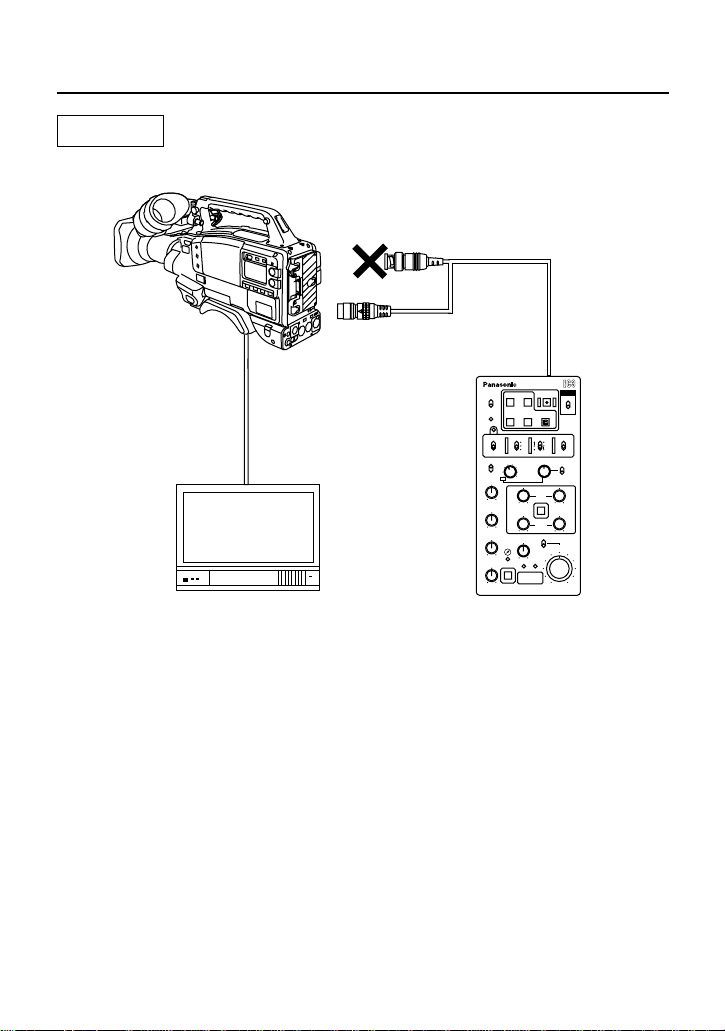
System connections
The unit is connected to a camera recorder, monitor, etc. for use. The examples illustrated here
show the system connections for mode 1 and modes 2/3.
ECU
ECU AJ-
RB
65
∫
1
Mode 1
Camera recorder
Monitor
BNC cable
BNC cable
6-pin cable
To VIDEO IN connector
To VIDEO OUT connector
To VIDEO OUT connector
AJ-EC3P
To CAM/BS
connector
To ECU connector
Cable (included)
Page 6
E-5
System connections
The BNC cable end of the cable (included) is not used in mode 2 or 3. Run it alongside the 6-pin
cable and secure it.
<Notes>
≥ For details on the connection of the camera recorder, monitor or other units, refer to their
respective Operating Instructions.
≥ An RCOP cable must be obtained separately if the model AJ-BS900P is going to be used.
Consult your dealer.
Modes 2/3
ECU
ECU AJ-
RB
65
∫
1
Camera recorder
Monitor
BNC cable
BNC cable
6-pin cable
To VIDEO IN connector
AJ-EC3P
To CAM/BS
connector
To ECU connector
Cable (included)
To VIDEO OUT connector
(AJ-HDC20A:
To HD HDI OUT connector)
Page 7
English
E-6
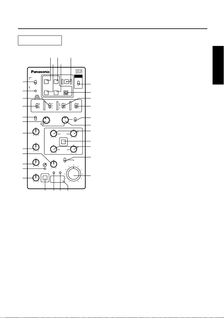
Parts and their functions
ENABLE
WARNING
REW
STOP
FF
ECU
ECU AJ-
START/STOP
PLAY
REC CHK
ON
OFF
ON
OFF
AWB
ABB
SHUTTER
KNEE POINT
KNEE SLOPE
GAMMA
DETAIL
SET UP
PAINTING
ENABLE
IRIS
GAIN
AUTO
MANUAL
GAIN
M.PED
CHECK
FILTER
RB
BLACK
W.BAL CAM
AUTO
KNEE
ON
PRST
A
B
UP
OFF
ON
OFF
ON
S.S.
(
PUSH
)
OFF
DOWN
BARS
GAIN
S.V
100(60)
120
250
500
1000
2000
65
∫
1
I
1
2
3
4
5
6
8
9
:
;
7
<
=
>
?
@
A
B
C
D
E
F
G
H
J
K
L
M
N
O
P
V
T
R
Control panel
VTR ENABLE switch
This enables the VTR operations 2 through 7 to be performed on the unit.
ON : The operations performed by the unit are enabled. The time code is displayed.
OFF : The operations performed by the unit are disabled. The time code is not displayed.
7
8
9
WARNING indicator
This lights up to indicate that a VTR error has occurred.
6
STOP button
Press this to stop the tape travel.
PLAY (playback) button
Press this to view the playback images on the
camera recorder’s viewfinder or on a color video
monitor if one is being used. Its LED remains
lighted during playback.
1
Power switch
Main power ON/OFF switch of the AJ-EC3P.
2
REC CHK button
It is possible to check what has just been recorded
(2-second rec review) by pressing this button
during rec pause. When it is pressed during play
pause, the tape is cued to provide continuity from
one shot to the next.
START/STOP button
When this is pressed, the camera recorder starts
recording; when it is pressed again, it stops
recording. This button works in exactly the same
way as the camera recorder’s VTR start button. Its
LED remains lighted during recording.
FF (fast forward) button
Press this to fast forward the tape. Its LED
remains lighted during fast forwarding.
3
4
REW (rewind) button
Press this to rewind the tape. Its LED remains
lighted during rewinding.
5
Page 8

E-7
Parts and their functions
W.BAL switch
PRST : Set to this position if there is no time to adjust the white balance. The 3200K white
balance value is stored in the memory as the presetting.
A or B : When the = AWB / ABB switch is set to the AWB position, the white balance is
automatically adjusted, and the value adjusted is stored in memory A or memory B.
The white balance value corresponding to the FILTER control position can also be stored in
the memory by setting FILTER INH to OFF. For further details, refer to the respective pages
in the Operating Instructions of the camera recorder being used.
<
;
CAM AUTO KNEE / BARS switch
This selects the video signals to be output from the camera area to the VTR area, viewfinder
and video monitor.
∫ Setting positions of CAM AUTO KNEE/BARS switch
BARS : Color bar signals are output.
Set the switch to this position in the following circumstances:
≥When the video monitor is to be adjusted
≥When color bar signals are to be recorded
CAM.AUTO KNEE OFF
: The images shot by the camera are output. The AUTO KNEE circuit
does not work. MANUAL KNEE is set as the camera recorder’s
initial setting.
CAM.AUTO KNEE ON
: The images shot by the camera are output.
The AUTO KNEE circuit works.
AWB / ABB (auto white balance / auto black balance adjustment) switch
AWB: Set here for the white balance to be adjusted automatically.
When the < W.BAL switch is set to A or B at this time, the value to which the balance
was adjusted will be stored in memory A or memory B.
ABB : Set here for the black balance to be adjusted automatically. The value to which the
balance was adjusted will be stored in a dedicated memory.
=
?
SETUP dial
This is used to set the SETUP menus. After a menu has been selected using the dial, press
the dial to enter it.
>
SETUP switch
This displays the SETUP menus at the VIDEO OUT connector.
@
SHUTTER switch
Set this to ON when the electronic shutter is to be used.
A
SHUTTER SPEED selector switch
This selects the shutter speed or SUPER V when the @ SHUTTER switch is ON. At the S.S.
setting, the shutter speed is changed using the SETUP dial.
:
GAIN (gain selector) switch
This is used to select the video amplifier’s gain depending on the lighting conditions that
prevail during shooting.
<Note>
If the camera recorder’s GAIN setting has been set on the AJ-EC3P to a value exceeding 30
dB, it will be canceled when the power is turned off and then automatically set to 30 dB when
the power is turned back on.
Page 9

English
E-8
Parts and their functions
C
PAINTING ENABLE switch
This is used to enable the PAINTING GAIN and BLACK VR controls.
B
PAINTING GAIN VRs
R GAIN and B GAIN controls
K
INDICATOR
This lights when a lens extender is used.
L
M.PED VR
This is used to set the master pedestal.
M
Number display LED
The iris value and the gain or filter positions are displayed on this LED. Normally, the iris
value is shown but when the gain value or filter position has been changed, the respective
value is displayed.
DETAIL VR
This enables both H DETAIL and V DETAIL to be varied at the same time.
J
H
IRIS VR
When the G AUTO IRIS switch is ON, this control adds the control value to, or subtracts it
from, the IRIS LEVEL on the user menu. This addition or subtraction is performed over a
range of -2 steps to +2 steps. When the same switch is OFF, it is used to adjust the iris finely.
I
GAMMA VR
This enables the camera’s master gamma to be varied in 0.01 steps from 0.35 to 0.65.
G
AUTO IRIS switch
AUTO IRIS ON/OFF switch
D
PAINTING BLACK VR
R PEDESTAL and B PEDESTAL controls
F
KNEE SLOPE VR
This is used to set the manual knee slope.
E
KNEE POINT VR
This is used to set the manual knee point.
N
CHECK switch
The gain value, filter position and iris value are displayed in this order on the number display
LED by pressing this switch. The iris display is restored after a prescribed period of time has
elapsed.
O
GAIN INDICATOR
This lights when the gain value is shown on the number display LED.
P
FILTER INDICATOR
This lights when the filter position is shown on the number display LED.
Page 10

E-9
Parts and their functions
1
2
1
CAM/BS connector
This is used to connect the unit with the camera
recorder or AJ-BS900P.
2
VIDEO OUT connector
The video signals with characters added are output
to this connector.
Connector area
Page 11
English
E-10
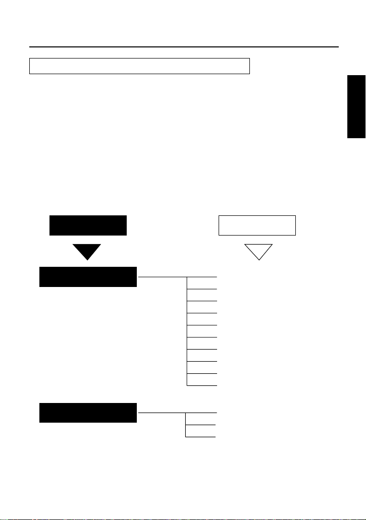
Menu displays for VIDEO OUT output
When the SETUP switch is set to ON, the setting menus are displayed in the VIDEO OUT output.
There are two kinds of setting menus, main menus and sub menus. The setting menus are
displayed page by page. All the pages contained in these menus and the page configuration are
shown below.
<Note>
≥
The setting menus are not output from the unit when the AJ-HDC20A is connected. Connect the
AJ-HDC20A’s output to the monitor and display the menus on the monitor.
≥
Only the menus will be output also when no signals are supplied to the camera recorder’s VIDEO
OUT connector.
Configuration of setting menus
MAIN MENU
MAIN MENU 1/2
MAIN MENU 2/2
SUB MENU
1 SYNCHRO SCAN
2 VR DATA
3 MATRIX
4 DTL SETTING
5 ADDITIONAL DTL
6 SKIN TONE DTL
7 KNEE / LEVEL
8 FLARE / GAMMA
9 GENLOCK / IRIS
: CAMERA SW MODE
; CAMERA SETTING
< AUTO SHADING
= DIAGNOSTIC
Setting menu display for VIDEO OUT output
Page 12

E-11
MAIN MENU 1 of 2
1
SYNCHRO SCAN screen
< SYNCHRO SCAN >
SYNCRO SCAN 1/50.6
2
VR DATA screen
< VR DATA >
MASTER PED : +000
MASTER DTL : +00
MASTER GAMMA : 0.45
KNEE POINT : 085%
KNEE SLOPE : +000
B GAIN : +000
R PEDESTAL : +000
B PEDESTAL : +000
<Note>
Data setting operations using the SETUP dial
cannot be performed on this menu.
<Note>
Regardless of whether the previous setting
was ON or OFF, OFF is always selected for the
SKIN TONE ZEBRA item when the SKIN TONE
DTL screen has been opened.
< MATRIX >
MATRIX TABLE : A
MATRIX R-G : +11
MATRIX R-B : +09
MATRIX G-R : +05
MATRIX G-B : +15
MATRIX B-R : +11
MATRIX B-G : +11
3
MATRIX screen
4
DTL SETTING screen
< DTL SETTING >
H.DTL LEVEL : 10
D.DTL LEVEL : 10
DTL CORING : 03
H.DTL FREQ. : 03
DARK DTL : 00
LEVEL DEPEND. : 00
BLACK STRETCH : OFF
MATRIX TABLE : A
< ADDITIONAL DTL >
C DTL COMPE. : OFF
CHROMA DTL : 0
KNEE APERTURE : ON
SLIM DTL : OFF
CORNER DTL : ON
DTL GAIN(+) : +00
DTL GAIN(
-
):+16
DTL CLIP : 00
H.DTL LINE MIX : 1H
5
ADDITIONAL DTL screen
6
SKIN TONE DTL screen
< SKIN TONE DTL >
SKIN TONE DTL : OFF
SKIN TONE HUE : 103
SKIN TONE LEVEL : 25
SKIN TONE WIDTH : 15
SKIN TONE CORING : 05
SKIN TONE ZEBRA : OFF
Page 13

English
E-12
< GENLOCK / IRIS >
A.IRIS LEVEL : 050
A.IRIS PEAK/AVE : 050
A.IRIS MODE : NORM1
GEN LOCK : INT
H PHASE COARSE : 07
H PHASE FINE : 128
SC PHASE COARSE: 0
SC PHASE FINE : 128
9
GENLOCK/IRIS screen
MAIN MENU 1 of 2
< FLARE / GAMMA >
R FLARE : 000
G FLARE : 000
B FLARE : 000
R GAMMA : +00
B GAMMA : +00
8
FLARE/GAMMA screen
< CAMERA SW MODE >
SUPER V MODE : FRM1
FILTER INH : ON
SHOCKLESS AWB : NORMAL
:
CAMERA SW MODE screen
7
KNEE/LEVEL screen
< KNEE / LEVEL >
MANUAL KNEE : ON
WHITE CLIP : ON
WHITE CLIP LVL : 105%
AUTO KNEE POINT : 085
AUTO KNEE LVL : 105
SET UP : 7.5%A
<Notes>
≥
The current setup level set by the camera
recorder is displayed for SET UP. It cannot
be set from the unit.
≥
SET UP will not be displayed when the unit
is connected to a PAL system camera.
<Note>
For further details on the menus, refer to the respective pages in the Operating Instructions of the
camera recorder being used.
Page 14

E-13
MAIN MENU 2 of 2
< CAMERA SETTING >
DETAIL : ON
2D LPF : OFF
SUPER COLOR : ON
GAMMA : ON
TEST SAW : OFF
FLARE : ON
H-F COMPE. : ON
NEGATIVE DTL : ON
;
CAMERA SETTING screen
<
AUTO SHADING screen
< AUTO SHADING >
BLACK
WHITE
BLACK COMPE. : ON
WHITE COMPE. : ON
=
DIAGNOSTIC screen
< DIAGNOSTIC >
VERSION : Ver<¢.¢.¢>
UP DATE :
¢¢¢¢.¢¢.¢¢
<Note>
For further details on the menus, refer to the respective pages in the Operating Instructions of the
camera recorder being used.
Page 15

English
E-14
Shading adjustment
When performing shading using the BLACK and WHITE items on the AUTO SHADING screen,
proceed with the menu operations using the following black shading example as a reference.
< AUTO SHADING >
BLACK
WHITE
BLACK COMPE. : ON
WHITE COMPE. : ON
ACTIVE OK?
YES
NO
1.Open the AUTO SHADING page of the sub-menus in MAIN
MENU 2 of 2.
2.Align the arrow with BLACK and press the SETUP dial.
A confirmation page for checking whether shading is to be
performed now appears.
3.When the shading is to be performed, align the arrow with
YES and press the SETUP dial. (“SHADING ACTIVE” then
appears in the center of the screen.) When the shading is
not going to be performed, align the arrow with NO and
press the SETUP dial: operation now returns to the AUTO
SHADING page.
4.Upon completion of the shading, operation is automatically
returned to the AUTO SHADING page.
This now completes the shading adjustment.
Confirmation page
Shading menu operation procedure (example: black shading)
Page 16

E-15
Specifications
Power requirements: DC 12 V
Consumption: 125 mA
Allowable ambient temperature: 32 to 104 F (0 to 40 oC)
Allowable relative humidity: 85% or less
Dimensions: 3-1/4" (W) x 1-15/16" (H) x 6-11/16" (D)
(excluding knobs)
(82 (W) x 50 (H) x 170 (D) mm)
Weight: 1.34 bs (610 g)
indicates safety items.
Page 17

E-16
English
Page 18

F-1
Table des matières
Nous vous remercions d’avoir choisi ce module de commande d’extension AJ-EC3P (qui sera
simplement appelé “l’appareil” dans la suite de ce mode d’emploi).
L’appareil offre de hautes performances et un grand choix de fonctions pour le support des
camescopes DVCPRO, DVCPRO50 et DVCPRO HD.
Caractéristiques.................................................................F-2
Avant l’utilisation...............................................................F-3
Raccordements du système .............................................F-4
Mode 1.......................................................................................................F-4
Modes 2/3 ..................................................................................................F-5
Les commandes et leurs fonctions..................................F-6
Panneau de commande.............................................................................F-6
Panneau des connecteurs .........................................................................F-9
Affichage des menus de la sortie vidéo
............................F-10
Réglage des menus de la sortie vidéo (VIDEO OUT)..............................F-10
Ecrans de MAIN MENU 1 de 2.........................................F-11
Ecrans de MAIN MENU 2 de 2.........................................F-13
Réglage de l’ombrage......................................................F-14
Procédure d’utilisation du menu Ombrage (exemple : ombrage du noir)
......F-14
Fiche technique................................................................F-15
ATTENTION:
POUR REDUIRE TOUT RISQUE DE FEU OU DE
CHOC ELECTRIQUE ET TOUT BROUILLAGE
PARASITE, UTILISER EXCLUSIVEMENT LES
ACCESSOIRES RECOMMANDES.
AVERTISSEMENT:
POUR REDUIRE TOUT RISQUE DE FEU OU DE
CHOC ELECTRIQUE, NE PAS EXPOSER
L’APPAREIL A LA PLUIE NI A L’HUMIDITE.
Informations concernant la sécurité
Page 19

F-2
Français
Caractéristiques
1. L’appareil permet de piloter la section magnétoscope des camescopes DVCPRO,
DVCPRO50 et DVCPRO HD.
≥ Un commutateur ENABLE empêche les erreurs de manipulation.
≥ Une LED signale les avertissements relatifs au magnétoscope.
2. Par le connecteur VIDEO OUT de l’appareil, il est possible d’envoyer des signaux vidéo
avec ajout de caractères (menus SETUP, etc.).
≥ Les menus SETUP ne s’affichant pas dans le viseur du magnétoscope, la caméra se
pilote avec les menus SETUP de l’EC3P même pendant la prise de vues.
≥ Il est possible d’envoyer les écrans des menus SETUP même en l’absence de
signaux vidéo.
3. L’appareil offre les fonctions et les écrans suivants qui ont été ajoutés aux modèles
existants, AQ-EC1 et AJ-EC2.
≥ Les fonctions de réglage de la qualité des images DETAIL, GAMMA, KNEE SLOPE
et KNEE POINT ont été incorporées.
≥ Les réglages d’ emplacement de GAIN, IRIS et FILTER sont maintenant affichés sur
une LED à 7 segments.
≥ Les positions S.S et S.V ont été ajoutées dans la section du commutateur
SHUTTER.
Les réglages de balayage synchrone s’effectuent avec la molette SETUP.
≥ La fonction PAINTING (R/B GAIN, R/B BLACK) ENABLE a été ajoutée.
≥ Des LED pour l’affichage de ABB/AWB OK/NG ont été incorporées.
≥ Un codeur rotatif permet de sélectionner les menus SETUP.
4. L’organisation des menus SETUP sous forme hiérarchique facilite la sélection des menus
et renforce la convivialité.
5. L’appareil identifie automatiquement les camescopes qui n’incorporent pas le protocole
EC3P, et il commute sur un mode qui permet d’exécuter les mêmes fonctions que celles
des modèles existants AQ-EC1 et AJ-EC2.
Caractéristiques
<Remarque>
Avec certains magnétoscopes, il n’est pas toujours possible d’utiliser toutes les fonctions cidessus. Pour les détails, voir “Avant l’utilisation” (page F-3).
Page 20

F-3
Avant l’utilisation
Selon le camescope, il est possible que les fonctions de l’appareil soient limitées. En
conséquence, avant l’utilisation, vérifier le modèle du camescope et les fonctions qui peuvent être
utilisées.
<Remarque>
Si le modèle que l’on possède ne figure pas dans la liste ci-dessus, consulter son revendeur.
AJ-D910WA
D610WA
Modèle Fonctions qui peuvent être utilisées
Mode 1 Toutes les fonctions de l’appareil sont opérationnelles. Toutefois,
avec les versions anciennes de logiciel, il faudra effectuer une
mise à niveau. Consulter son revendeur.
AJ-HDC20A
BS900
Mode 2 L’envoi des signaux vidéo n’est pas possible.
Toutes les fonctions de l’appareil sont opérationnelles.
AJ-D810
D700A
D700
D400
Mode 3 1.Aucune des opérations du magnétoscope (START/STOP, FF,
REW, STOP et PLAY REC CHECK) n’est possible.
2.Les commandes GAMMA, KNEE SLOPE, KNEE POINT et
DETAIL ne sont pas opérationnelles.
3.La vitesse d’obturation se règle sur 1/60ème ou 1/100ème si
l’on sélectionne S.S. ou S.V avec le sélecteur SHUTTER.
4.Les paramètres de FILTER ne s’affichent pas.
Seul l’affichage à LED de GAIN ou IRIS peut être sélectionné
avec la touche CHECK.
5.Les menus SETUP ne sont pas les menus de l’appareil. Les
menus du camescope sont envoyés par le connecteur VIDEO
OUT du camescope. Les menus ne sont pas envoyés au
connecteur VIDEO OUT de l’appareil.
6.Seule la sélection de L, M ou H est possible avec le sélecteur
GAIN, et ces paramètres s’affichent comme 0, 9 et 18 sur
l’affichage à LED.
7.PAINTING est toujours désactivé.
Page 21

F-4
Français
Raccordements du système
L’appareil se raccorde à un camescope, un moniteur, etc. Les exemples montrent les
raccordements du système pour le mode 1 et les modes 2/3.
ECU
ECU AJ-
RB
65
∫
1
Mode 1
Camescope
Moniteur
Câble BNC
Câble BNC
Câble à 6 broches
Vers le connecteur VIDEO IN
Vers le connecteur VIDEO OUT
Vers le connecteur VIDEO OUT
AJ-EC3P
Vers le connecteur
CAM/BS
Vers le connecteur ECU
Câble (fourni)
Page 22

F-5
Raccordements du système
L’extrémité de câble BNC du câble (fourni) ne sert pas en mode 2 ou 3. On l’acheminera le long du
câble à 6 broches et on la fixera.
<Remarques>
≥ Pour les détails sur le raccordement du camescope, du moniteur ou de tout autre appareil, voir le
mode d’emploi de l’appareil en question.
≥ Avec le modèle AJ-BS900P, il faudra se procurer un câble RCOP vendu séparément. Consulter
son revendeur.
Modes 2/3
ECU
ECU AJ-
RB
65
∫
1
Camescope
Moniteur
Câble BNC
Câble BNC
Câble à 6 broches
Vers le connecteur
VIDEO IN
AJ-EC3P
Vers le connecteur ECU
Câble (fourni)
Vers le connecteur
VIDEO OUT
(AJ-HDC20A :Vers le
connecteur HC HDI OUT)
Page 23

F-6
Français
Les commandes et leurs fonctions
ENABLE
WARNING
REW
STOP
FF
ECU
ECU AJ-
START/STOP
PLAY
REC CHK
ON
OFF
ON
OFF
AWB
ABB
SHUTTER
KNEE POINT
KNEE SLOPE
GAMMA
DETAIL
SET UP
PAINTING
ENABLE
IRIS
GAIN
AUTO
MANUAL
GAIN
M.PED
CHECK
FILTER
RB
BLACK
W.BAL CAM
AUTO
KNEE
ON
PRST
A
B
UP
OFF
ON
OFF
ON
S.S.
(
PUSH
)
OFF
DOWN
BARS
GAIN
S.V
100(60)
120
250
500
1000
2000
65
∫
1
I
1
2
3
4
5
6
8
9
:
;
7
<
=
>
?
@
A
B
C
D
E
F
G
H
J
K
L
M
N
O
P
V
T
R
Panneau de commande
Touche d’activation de magnétoscope (VTR ENABLE)
Elle permet de déclencher les opérations (2) à (7) du magnétoscope sur l’AJ-EC3P.
ON : Les opérations exécutées par l’EC3P sont activées. Le code temporel s’affiche.
OFF: Les opérations exécutées par l’EC3P sont désactivées. Le code temporel ne s’affiche
pas.
7
8
9
Indicateur d’avertissement (WARNING)
Il s’allume pour signaler qu’il s’est produit une erreur dans le magnétoscope.
6
Touche d’arrêt (STOP)
Appuyer sur cette touche pour arrêter la bande.
Touche de lecture (PLAY)
Appuyer sur cette touche pour visionner les images de lecture dans le viseur du camescope,
ou sur un moniteur couleur le cas échéant. La LED de la touche s’allume pendant la lecture.
1
Interrupteur d’alimentation
C’est l’interrupteur de mise sous/hors tension de
l’AJ-EC3P.
2
Touche de vérification d’enregistrement (REC
CHECK)
Il est possible de vérifier les images qui viennent
juste de s’enregistrer (revue d’enregistrement de 2
secondes) en appuyant sur cette touche pendant
une pause d’enregistrement. Si l’on appuie
pendant une pause de lecture, la bande est
repérée afin d’assurer la continuité des images
d’une prise de vues à l’autre.
Touche de marche/arrêt (START/STOP)
Quand on appuie sur cette touche, le camescope
commence à enregistrer ; si l’on appuie à nouveau,
l’enregistrement s’arrête. Cette touche fonctionne
exactement de la même façon que la touche de
marche de magnétoscope du camescope.
Touche d’avance rapide (FF)
Appuyer sur cette touche pour avancer la bande
rapidement. La LED de la touche s’allume pendant
l’avance rapide.
3
4
Touche de rembobinage (REW)
Appuyer sur cette touche pour rembobiner la
bande. La LED de la touche s’allume pendant le
rembobinage.
5
Page 24

F-7
Les commandes et leurs fonctions
Commutateur de réglage de la balance des blancs (W.BAL)
PRST : Mettre sur cette position lorsqu’on n’a pas le temps de régler la balance des blancs.
La valeur de balance des blancs de 3200 K a été préréglée en mémoire.
A ou B : Si le commutateur = AWB/ABB se trouve sur la position AWB, le réglage de la
balance des blancs s’effectue automatiquement, et la valeur est enregistrée dans la
mémoire A ou la mémoire B.
On pourra également enregistrer en mémoire la valeur de la balance des blancs
correspondant à la position de la commande FILTER en réglant FILTER INH sur OFF. Pour
les détails, voir les pages correspondantes du mode d’emploi du camescope utilisé.
<
;
Commutateur d’articulation automatique de camescope/mire de couleur (CAM AUTO
KNEE/BARS)
Il permet de sélectionner les signaux vidéo à envoyer par la section caméra à la section
magnétoscope, au viseur et au moniteur.
∫ Positions de réglage du commutateur CAM AUTO KNEE/BARS
BARS : L’appareil envoie les signaux de la mire de couleur.
Mettre le commutateur sur cette position dans les cas suivants :
≥Pour le réglage du moniteur vidéo
≥Pour l’enregistrement de la mire de couleur.
CAM.AUTO KNEE OFF
: L’appareil envoie les images prises par la caméra. Le circuit AUTO
KNEE ne fonctionne pas. MANUAL KNEE se règle au réglage initial
du camescope.
CAM.AUTO KNEE ON
: L’appareil envoie les images prises par la caméra.
Le circuit AUTO KNEE fonctionne.
Commutateur de réglage automatique de la balance des blancs/balance des noirs
(AWB/ABB)
AWB: Régler sur cette position pour effectuer un réglage automatique de la balance des
blancs.
W.BAL est réglé sur A ou B, la valeur de réglage de la balance s’enregistre dans la
mémoire A ou la mémoire B.
ABB : Régler sur cette position pour effectuer un réglage automatique de la balance des
noirs. La valeur de réglage de la balance s’enregistre dans une mémoire spéciale.
=
?
Molette d’initialisation (SETUP)
Elle permet de régler les menus SETUP. Quand un menu a été sélectionné avec la molette,
appuyer sur la molette pour le valider.
>
Commutateur d’initialisation (SETUP)
Il permet d’afficher les menus SETUP au connecteur VIDEO OUT.
:
Sélecteur de gain (GAIN)
Il permet de sélectionner le gain de l’amplificateur vidéo en fonction des conditions d’éclairage
qui prévalent pendant la prise de vues.
<Remarque>
Si le gain (GAIN) du camescope a été réglé sur l’AJ-EC3P à une valeur supérieure à 30 dB, il
s’annulera à la mise hors tension, puis il se réglera automatiquement à 30 dB à la prochaine
mise sous tension.
Page 25

F-8
Français
@
Commutateur d’obturateur (SHUTTER)
Le régler sur ON pour pouvoir utiliser l’obturateur électronique.
A
Sélecteur de vitesse d’obturation (SHUTTER SPEED)
Il permet de sélectionner la vitesse d’obturation ou la vitesse SUPER V lorsque le
commutateur @ SHUTTER est réglé sur ON. Sur S.S., la vitesse d’obturation se règle avec la
molette SETUP.
Les commandes et leurs fonctions
C
Commutateur PAINTING ENABLE
Permet d’activer les commandes PAINTING GAIN et BLACK VR.
B
PAINTING GAIN VR
Commandes R GAIN et B GAIN.
K
INDICATOR
S’allume lors de l’utilisation d’un prolongateur d’objectif.
L
M.PED VR
Permet de régler la suppression principale.
M
LED d’affichage de numéro
La valeur du diaphragme et le réglage du gain ou du filtre s’affichent sur cette LED.
Normalement, c’est la valeur du diaphragme qui s’affiche, mais si l’on modifie la valeur du
gain ou la position du filtre, c’est la valeur respective qui s’affiche.
DETAIL VR
Active à la fois H DETAIL et V DETAIL pour pouvoir les régler simultanément.
J
H
IRIS VR
Si le commutateur G AUTO IRIS est réglé sur ON, cette commande ajoute ou soustrait la
valeur de commande de IRIS LEVEL, sur le menu utilisateur. Cet ajout ou cette soustraction
s’effectuent sur une plage de -2 paliers à +2 paliers. Si le même commutateur est réglé sur
OFF, cette commande permet d’effectuer un réglage précis du diaphragme.
I
GAMMA VR
Active le niveau gamma principal de la caméra de façon à le régler de 0,35 à 0,65 par paliers
de 0,01.
G
Commutateur AUTO IRIS
C’est le commutateur de marche/arrêt du diaphragme automatique.
D
PAINTING BLACK VR
Commandes R PEDESTAL et B PEDESTAL.
F
KNEE SLOPE VR
Permet de régler la pente d’articulation manuelle.
E
KNEE POINT VR
Permet de régler le point d’articulation manuel.
Page 26

F-9
Les commandes et leurs fonctions
1
2
1
Connecteur CAM/BS
Il permet de raccorder l’appareil au camescope ou à
l’AJ-BS900P.
2
Connecteur VIDEO OUT
C’est par ce connecteur que sont envoyés les
signaux vidéo avec ajout de caractères.
Panneau des connecteurs
N
Commutateur CHECK
Quand on appuie sur cette touche, la valeur du gain, la position du filtre et la valeur du
diaphragme s’affichent dans cet ordre sur la LED d’affichage de numéro. L’affichage du
diaphragme revient à l’issue de l’intervalle de temps préréglé.
O
GAIN INDICATOR
Il s’allume quand la valeur du gain est affichée sur la LED d’affichage de numéro.
P
FILTER INDICATOR
Il s’allume quand la position du filtre est affichée sur la LED d’affichage de numéro.
Page 27

F-10
Français
Affichage des menus de la sortie vidéo
Lorsque le commutateur SETUP est réglé sur ON, les menus de réglage s’affichent à la sortie
VIDEO OUT. Il y a deux sortes de menus de réglage, les menus principaux et les menus
auxiliaires. Les menus de réglage s’affichent page par page. Nous donnons ci-après la liste des
pages de ces menus ainsi que la configuration de page.
<Remarque>
≥
Si l’on a raccordé l’AJ-HDC20A, les menus de réglage ne seront pas envoyés par l’appareil.
Raccorder la sortie de l’AJ-HDC20A au moniteur et afficher les menus sur le moniteur.
≥
Si le connecteur VIDEO OUT du camescope ne reçoit pas de signal vidéo, seuls les menus
seront également envoyés.
Configuration des menus de réglage
MAIN MENU
MAIN MENU 1/2
MAIN MENU 2/2
SUB MENU
1 SYNCHRO SCAN
2 VR DATA
3 MATRIX
4 DTL SETTING
5 ADDITIONAL DTL
6 SKIN TONE DTL
7 KNEE / LEVEL
8 FLARE / GAMMA
9 GENLOCK / IRIS
: CAMERA SW MODE
; CAMERA SETTING
< AUTO SHADING
= DIAGNOSTIC
Réglage des menus de la sortie vidéo (VIDEO OUT)
Page 28

F-11
Ecrans de MAIN MENU 1 de 2
1
Ecran SYNCHRO SCAN
< SYNCHRO SCAN >
SYNCRO SCAN 1/50.6
2
Ecran VR DATA
< VR DATA >
MASTER PED : +000
MASTER DTL : +00
MASTER GAMMA : 0.45
KNEE POINT : 085%
KNEE SLOPE : +000
B GAIN : +000
R PEDESTAL : +000
B PEDESTAL : +000
<Remarque>
Les opérations de réglage des données faisant
intervenir la molette d’initialisation ne
pourront pas être effectuées sur cet écran.
<Remarque>
Q
uand on ouvre l’écran SKIN TONE DTL, la
rubrique SKIN TONE ZEBRA se règle toujours
sur OFF, qu’elle ait été précédemment réglée
sur ON ou sur
OFF.
< MATRIX >
MATRIX TABLE : A
MATRIX R-G : +11
MATRIX R-B : +09
MATRIX G-R : +05
MATRIX G-B : +15
MATRIX B-R : +11
MATRIX B-G : +11
3
Ecran MATRIX
4
Ecran DTL SETTING
< DTL SETTING >
H.DTL LEVEL : 10
D.DTL LEVEL : 10
DTL CORING : 03
H.DTL FREQ. : 03
DARK DTL : 00
LEVEL DEPEND. : 00
BLACK STRETCH : OFF
MATRIX TABLE : A
< ADDITIONAL DTL >
C DTL COMPE. : OFF
CHROMA DTL : 0
KNEE APERTURE : ON
SLIM DTL : OFF
CORNER DTL : ON
DTL GAIN(+) : +00
DTL GAIN(
-
):+16
DTL CLIP : 00
H.DTL LINE MIX : 1H
5
Ecran ADDITIONAL DTL
6
Ecran SKIN TONE DTL
< SKIN TONE DTL >
SKIN TONE DTL : OFF
SKIN TONE HUE : 103
SKIN TONE LEVEL : 25
SKIN TONE WIDTH : 15
SKIN TONE CORING : 05
SKIN TONE ZEBRA : OFF
Page 29

F-12
Français
< GENLOCK / IRIS >
A.IRIS LEVEL : 050
A.IRIS PEAK/AVE : 050
A.IRIS MODE : NORM1
GEN LOCK : INT
H PHASE COARSE : 07
H PHASE FINE : 128
SC PHASE COARSE: 0
SC PHASE FINE : 128
9
Ecran GENLOCK/IRIS
Ecrans de MAIN MENU 1 de 2
< FLARE / GAMMA >
R FLARE : 000
G FLARE : 000
B FLARE : 000
R GAMMA : +00
B GAMMA : +00
8
Ecran FLARE/GAMMA
< CAMERA SW MODE >
SUPER V MODE : FRM1
FILTER INH : ON
SHOCKLESS AWB : NORMAL
:
Ecran CAMERA SW MODE
7
Ecran KNEE/LEVEL
< KNEE / LEVEL >
MANUAL KNEE : ON
WHITE CLIP : ON
WHITE CLIP LVL : 105%
AUTO KNEE POINT : 085
AUTO KNEE LVL : 105
SET UP : 7.5%A
<Remarques>
≥
Le niveau d’initialisation actuellement réglé
par le camescope s’affiche pour SET UP. Il
n’est pas possible de le régler surl’appareil.
≥
SET UP ne s'affiche pas si l'appareil est
raccordé à une caméra au format PAL.
<Remarque>
Pour les détails des menus, voir les pages correspondantes du mode d’emploi du camescope
utilisé.
Page 30

F-13
Ecrans de MAIN MENU 2 de 2
< CAMERA SETTING >
DETAIL : ON
2D LPF : OFF
SUPER COLOR : ON
GAMMA : ON
TEST SAW : OFF
FLARE : ON
H-F COMPE. : ON
NEGATIVE DTL : ON
;
Ecran CAMERA SETTING
<
Ecran AUTO SHADING
< AUTO SHADING >
BLACK
WHITE
BLACK COMPE. : ON
WHITE COMPE. : ON
=
Ecran DIAGNOSTIC
< DIAGNOSTIC >
VERSION : Ver<¢.¢.¢>
UP DATE :
¢¢¢¢.¢¢.¢¢
<Remarque>
Pour les détails des menus, voir les pages correspondantes du mode d’emploi du camescope
utilisé.
Page 31

F-14
Français
Réglage de l’ombrage
Pour effectuer l’ombrage avec les rubriques BLACK et WHITE de l’écran AUTO SHADING,
procéder comme indiqué ci-dessous dans l’exemple d’ombrage du noir, donné à titre de référence.
< AUTO SHADING >
BLACK
WHITE
BLACK COMPE. : ON
WHITE COMPE. : ON
ACTIVE OK?
YES
NO
1.Ouvrir la page AUTO SHADING du menu auxiliaire de
MAIN MENU 2 de 2.
2.Amener la flèche en regard de BLACK et appuyer sur
molette d’initialisation (SETUP).
Une page de confirmation s’affiche pour vérifier si
l’ombrage doit être effectué.
3.Pour effectuer l’ombrage, amener la flèche en regard de
YES et appuyer sur molette d’initialisation (SETUP).
(“SHADING ACTIVE” s’affiche au centre de l’écran.) Si l’on
ne veut pas effectuer l’ombrage, amener la flèche en regard
de NO et appuyer sur molette d’initialisation (SETUP) :
l’écran revient à la page AUTO SHADING.
4.Lorsque l’ombrage est terminé, l’écran revient
automatiquement à la page AUTO SHADING.
Le réglage de l’ombrage est terminé.
Page de confirmation
Procédure d’utilisation du menu Ombrage (exemple : ombrage du noir)
Page 32

F-15
Fiche technique
Alimentation : 12 V CC
Consommation : 125 mA
Température ambiante admissible : 0 à 40°C
Humidité relative admissible : 85% maximum
Dimensions : 82(L) x50(H) x170(P) mm (sans les boutons)
Poids : 610 g
Informations concernant la sécurité
Page 33

F-16
Français
Page 34

Printed in Japan
VQT8843
j i
F1000T
@
PANASONIC BROADCAST & DIGITAL SYSTEMS COMPANY
DIVISION OF MATSUSHITA ELECTRIC CORPORATION OF AMERICA
Executive Office:
3330 Cahuenga Blvd W., Los Angeles, CA 90068 (323) 436-3500
EASTERN ZONE:
One Panasonic Way 4E-7, Secaucus, NJ 07094 (201) 348-7621
Mid-Atlantic/New England:
One Panasonic Way 4E-7, Secaucus, NJ 07094 (201) 348-7621
Southeast Region:
1225 Northbrook Parkway, Ste 1-160, Suwanee, GA 30024 (770) 338-6835
Central Region:
1707 N Randall Road E1-C-1, Elgin, IL 60123 (847) 468-5200
WESTERN ZONE:
3330 Cahuenga Blvd W., Los Angeles, CA 90068 (323) 436-3500
Dallas Region:
6226 Abington Way, Houston, TX 77008 (713) 802-2726
No. CA/Northwest Region:
5870 Stoneridge, #3, Pleasanton, CA 94588 (925) 416-5108
Government Marketing Department:
52 West Gude Drive, Rockville, MD 20850 (301) 738-3840
PARTS INFORMATION & ORDERING:
9:00 a.m. – 5:00 p.m. (EST) (800) 334-4881/24 Hr. Fax (800) 334-4880
TECHNICAL SUPPORT:
Emergency 24 Hour Parts & Service (800) 222-0741
TRAINING INFORMATION:
Digital System Products - (201) 392-6852
Panasonic Canada Inc.
5770 Ambler Drive, Mississauga, Ontario L4W 2T3 (905) 624-5010
Panasonic de Mexico S.A. de C.V.
Av angel Urraza Num. 1209 Col. de Valle 03100 Mexico, D.F. (52) 1 951 2127
P
 Loading...