

Panasonic AJ-D650P, AJ-D640P, AJ-D640 User Manual
Digital Video Cassette Recorder
Operating Instructions
S0896H4037-300
@
VQT6816-3

IMPORTANT
“Unauthorized recording of copyrighted television programs, video tapes and other materials
may infringe the right of copyright owners and
be contrary to copyright laws.”
CAUTION: TO REDUCE THE RISK OF ELECTRIC SHOCK,
REFER SERVICING TO QUALIFIED SERVICE PERSONNEL.
I
DO NOT REMOVE COVER (OR BACK).
NO USER-SERVICEABLE PARTS INSIDE.
The lightning flash with arrowhead symbol, within an
equilateral triangle, is intended to alert the user to the
presence of uninsulated “dangerous voltage” within
the product’s enclosure that may be of sufficient
magnitude to constitute a risk of electric shock to
persons.
The exclamation point within an equilateral triangle is
intended to alert the user to the presence of important
operating and maintenance (servicing) instructions in
the literature accompanying the appliance.
WARNING:
To reduce the risk of fire or shock hazard,
do not expose this equipment to rain or
moisture.
I
CAUTION:
TO REDUCE THE RISK OF FIRE OR
SHOCK HAZARD, REFER MOUNTING OF
THE OPTIONAL INTERFACE BOARD TO
AUTHORIZED SERVICE PERSONNEL.
FCC Note:
This device complies with Part 15 of the FCC Rules.
To assure continued compliance follow the attached
installation instructions and do not make any
unauthorized modifications.
CAUTION:
To reduce the risk of fire or shock hazard and
annoying interference, use the recommended
accessories only.
is the safety information.
Do not insert fingers or any objects into the video
casette holder.
Avoid operating or leaving the unit near strong
magnetic fields. Be especially careful of large audio
speakers.
Avoid operating or storing the unit in an excessively
hot, cold, or damp environment as this may result in
damage both to the recorder and to the tape.
Do not spray any cleaner or wax directly on the unit.
If the unit is not going to be used for a length of time,
protect it from dirt and dust.
Do not leave a cassette in the recorder when not in
use.
Do not block the ventilation slots of the unit.
This equipment has been tested and found to comply
with the limits for a Class A digital device, pursuant to
Part 15 of the FCC Rules. These limits are designed
to provide reasonable protection against harmful
interference when the equipment is operated in a
commercial environment. This equipment generates,
uses, and can radiate radio frequency energy and, if
not installed and used in accordance with the instruction manual, may cause harmful interference to radio
communications. Operation of this equipment in a
residential area is likely to cause harmful interference
in which case the user will be required to correct the
interference at his own expense.
Use this unit horizontally and do not place anything on
the top panel.
Cassette tape can be used only for one-side, one
direction recording. Two-way or two-track recordings
cannot be made.
Cassette tape can be used for either Color or Black &
White recording.
Do not attempt to disassemble the recorder.
There are no user serviceable parts inside.
If any liquid spills inside the recorder, have the recorder
examined for possible damage.
Refer any needed servicing to authorized service
personnel.
–2–
Contents
General and Features.....................................................4
Controls and their functions
Controls and their functions...........................................6
• Front panel...................................................................7
• Connector area...........................................................11
• Tapes.........................................................................14
Connections and settings
Connections..................................................................15
• When recording/playback using 1 unit......................15
• When recording, playback and editing
with 2 units...............................................................16
• When using an editing controller..................................17
• Internal encoder adjustments.......................................18
• Printed circuit board....................................................20
Basic operations
Switching on the power/inserting the cassette.............21
STOP mode................................................................22
Recording...............................................................23
Playback.................................................................24
Setup menus
Setup (default settings).............................................25
Setup (setting) menus................................................26
System menu...............................................................27
Basic menu..................................................................27
• Operation menu..........................................................28
• Interface menu............................................................30
• Edit menu..................................................................31
• Tape protect menu......................................................32
• Time Code menu.........................................................33
• Video menu................................................................34
• Audio menu................................................................36
Time code
Time code/user bit.......................................................38
Recording internal/external time codes...........................39
Reproducing the time code/user bit.............................40
Functions
Superimpose screen...................................................41
Servo reference............................................................42
Audio V Fade Function (AJ-D650 only).......................44
Maintenance
Rack mounting.............................................................45
Head cleaning..............................................................46
Condensation................................................................46
Error messages............................................................47
Specifications and others
Connector signals.........................................................49
Specifications................................................................51
Before operating this unit, check that all of its accessories are present and accounted for.
Power cord....1 pc
Option
• AJ-YA750P component serial interface board
• AJ-CS750P Cassette adaptor
• AJ-MA75P Rack mounting adaptor
• Digital Audio Interface Board AJ-YA655P
–3–

General and Features
This unit is a digital video cassette recorder which uses 1/4-inch tapes.
It incorporates digital compression technology so that the deterioration in picture quality and
sound quality resulting from dubbing is significantly minimized compared with existing
analog systems.
Furthermore, since it has a compact 4U size and light weight, the unit can be carried around
or mounted in a 19-inch rack with ease.
The settings for the unit’s setup can be performed while viewing the screen menus on the
TV monitor. With the AJ-D650 unit, both assemble and insert editing are possible through
external control.
Features
Compact size and light weight
This is a 4U size digital VTR. It can be mounted in a 19-inch rack with ease using the
optional rack-mounting adaptors (AJ-MA75P).
Up to 123 minutes of recording
Two sizes of cassette tapes can be used with this unit: M cassette (max. 63 minutes) and L
cassette (max. 123 minutes).
compact design.
Compatibility with consumer products
Consumer cassette tapes shot with digital cameras available on the consumer market can
be played back on this unit using the optional cassette adaptor (AJ-CS750P).
<Notes>
• Slow motion playback is not possible with consumer cassette tapes.
• Consumer cassette tapes recorded in LP mode cannot be played back.
The width of the tapes measures 1/4 inch to achieve a
Digital slow motion/jog
The slow motion playback images can be reproduced clearly at any of the speeds given below
using commands from the external controller or other such device: –0.43/–0.3/–0.2/–0.1/
–0.03/0/+0.03/+0.1/+0.2/+0.3/+0.5/+0.75.
<Notes>
• Some noise may occur when the slow motion speed is changed.
• When slow motion playback is used, the image shakes slightly in the vertical direction.
Dialy shuttle operation is possible through the external controller
Shuttle operations enable the tape to be played back with color images at a speed of up to
60 times normal tape speed in either the forward or reverse direction.
Time codes
This unit comes with a built-in time code generator (TCG)/time code reader (TCR). In
addition to the internal time code, an external time code input or input signal VITC can be
recorded in the machine as the LTC time code.
–4–

Features
(continued)
Multi-function input/output interfaces
• Analog input/output
Component (Y, PB, PR) and composite and S-VIDEO signal input and output connectors are
provided.
• Digital audio input/output
AES/EBU audio input/output is possible when the optional digital audio interface board (AJYA655P) is used.
• Serial digital input/output
Serial digital (SMPTE 259M-C, 272M) input/output is possible when the optional component
serial interface board (AJ-YA750P) is used.
<Note>
The AJ-YA655P board, sold separately, is necessary when using serial digital audio
(SMPTE 272M).
• 9-pin (RS-422A)/(RS-232C, option) remote
The standard 9-pin serial (RS-422A) connector or an optional RS-232C connector is used.
2-channel high-sound-quality digital audio
Sound can be edited separately for two channels, and channel mixing capabilities are also
available. One channel is provided for the analog cue track.
Information selected from audio CH1 and CH2 can be recorded in the cue track memory.
(Set at the set up menu.)
• Cue track input and output connectors are not provided.
Automatic editing functions from the external controller (only AJ-D650)
AJ-D650 allows both assemble and insert editing from the external controller.
Menu-driven setup
The setup settings, which are conducted prior to operating the unit, are performed while
viewing the setup menus either on the unit display or TV monitor.
–5–
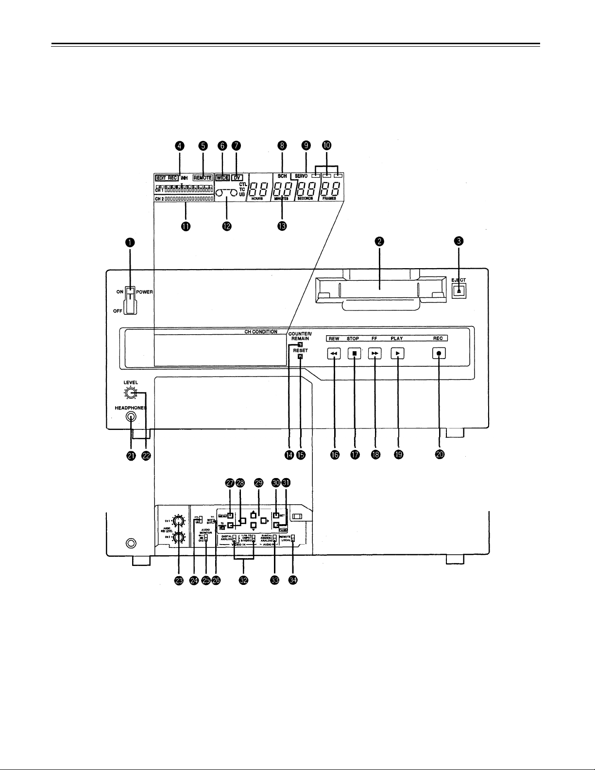
Controls and their functions
Front panel
Counter Display Section
–6–

POWER switch
When the ON side is pressed, the power is switched on, and the counter display lights up
Cassette insertion slot
The M cassette, L cassette and consumer cassette (S cassette) with adaptor are inserted
into this slot.
Consumer cassettes can be played back only.
EJECT button
When this is pressed, the tape is unloaded and several seconds later the cassette is
automatically ejected. When the counter display indicates “CTL”, the display is reset.
EDIT/EDIT REC/REC/REC INH lamps
EDIT:
EDIT REC: This lights when editing from the 9P remote control.
REC:
REC INH:
REMOTE lamp
This lights when the REMOTE/LOCAL switch has been set to the REMOTE position.
WIDE lamp
This lights when the unit is in 16:9 wide screen mode.
This lights when the editing mode is chosen from the 9P remote control.
This lights during video recording.
This lights when the accidental erasure prevention mode has been set for the
cassette. In this state, neither recording nor editing is possible.
Consumer cassette insertion display lamp
This lights when a cassette recorded on a consumer DV device has been inserted.
SCH lamp
This lights when the SCH of the external sync signal is within a specific range.
SERVO lamp
This lights when the drum servo and capstan servo have locked.
Channel condition lamps
One of these lamps lights in accordance with the error rate status. (Green blue
Green: This lights when the error rates for the video and audio playback signals are
both acceptable.
Blue:
Red:
Level meters
These indicate the PCM audio signal CH1/CH2.
The audio signal indicates the input signal levels during recording and EE selection, and
the output signal levels during playback.
Cassette insertion display lamp
This lights when a cassette has been inserted into the unit.
This lights when the error rate for the video or audio playback signals has
deteriorated.
The playback picture will remain normal even when this lamp lights.
This lights when the video or audio signals are subject to rectification or
interpolation.
red)
Counter display
This displays the TC and CTL count values, on-screen information and other messages.
–7–

Controls and their functions
COUNTER/REMAIN button
This switches between the tape counter tape time indicator and the remaining tape
indicator. [r ***] is displayed in the case of the remaining tape indicator. After the
cassette tape is inserted, [r ---] (--- flashes) is displayed until remaining tape is
calculated, and [r EJ] (EJ flashes) when ejecting the tape.
RESET button
When this is pressed during CTL mode, the counter returns to the 00:00:00:00 display.
During menu setup, initial setting values are restored when the RESET button is pressed.
(continued)
REW button
The tape is rewound when this is pressed.
The unit goes into shuttle (SHTL) mode at -9.5 × normal tape speed when this button is
pressed together with the PLAY button.
STOP button
When this is pressed, the tape stops traveling, and if the setup menu No. 111 (STOP EE
SEL) is set to TAPE, still pictures can be monitored.
The drum continues to rotate even in the stop mode, and the tape remains in close
contact with the drum.
If the stop mode continues for more than a certain period of time, the unit automatically
switches to the standby OFF mode in order to protect the tape.
The stop mode is established immediately after a cassette has been inserted into the
unit.
FF button
The tape is fast forwarded when this is pressed.
The unit goes into shuttle (SHTL) mode at +9.5 × normal tape speed when this button is
pressed together with the PLAY button.
PLAY button
Playback commences when this button is pressed.
Recording commences when the button is pressed together with the REC button.
*¹)
*¹)
REC button
Recording commences when this button is pressed together with the PLAY button.
When it is pressed during playback, search
and audio signals can be monitored for as long as it is kept depressed.
When it is pressed in the stop mode, EE mode images and sound can be monitored.
When the STOP button is pressed, the original picture and sound are restored.
*1)
The FF/REW speed can be selected on the setup menu NO. 102 (FF, REW MAX), and it
is set to the same speed.
*2)
No guarantee is made for the audio EE mode.
*2)
,
fast forward or rewind, EE mode images
–8–
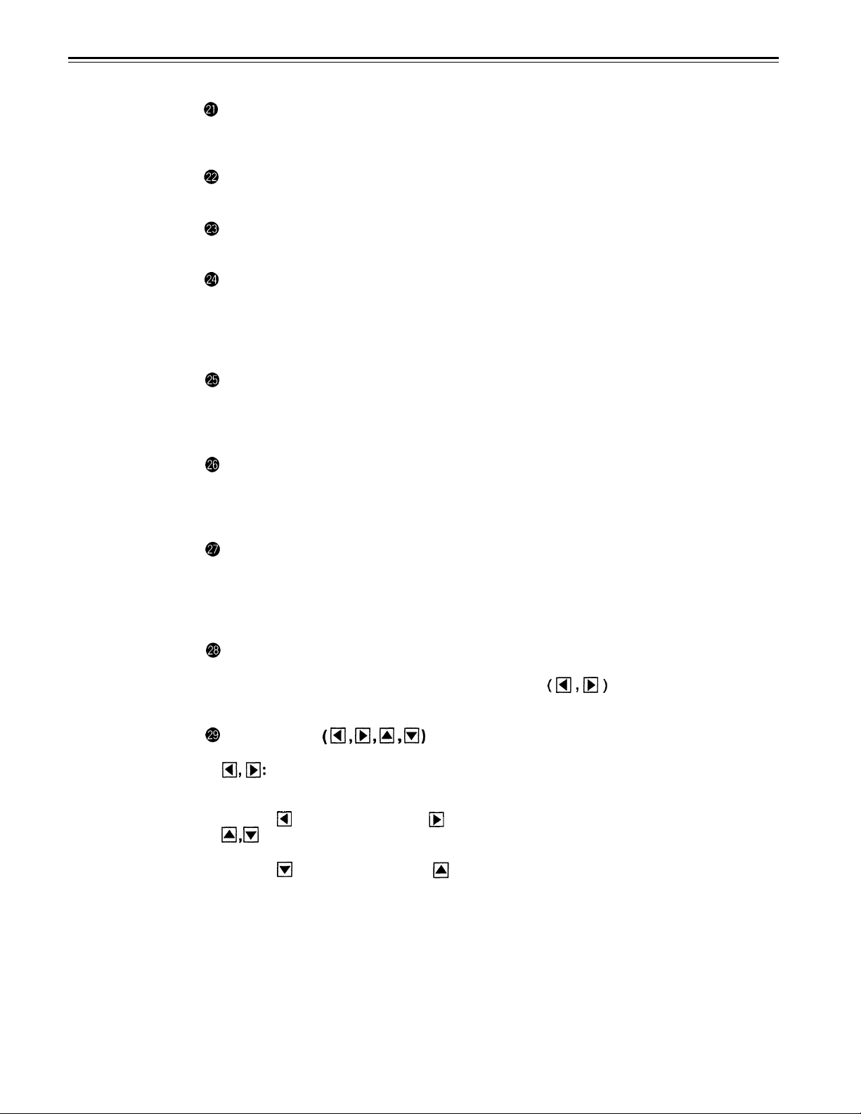
Headphones jack
The sound being recorded, played back or edited can be monitored on stereo
headphones when they are connected to this jack.
Volume control
This is used to adjust the headphones volume.
Audio recording level controls
These are used to adjust the recording levels of the analog audio signal CH1/CH2.
CTL/TC/UB switch
Use this switch when selecting the counter display.
CTL:
Tape timer (control signal) is displayed.
TC: Time code is displayed.
UB: User bit is displayed.
MONITOR SELECT switch
This is used to select the audio signals output to the monitor channel.
(With the No. 713 (MONI CH SEL) setting on the setup menu, the display may not match
the monitor output.)
INT/EXT switch
INT:
EXT:
For using the built-in time code generator.
For using the time external code which is input from the time code input connector
or the video signal VITC. The selection is set at the setup menu.
MENU button
When this is pressed, the setup menu appears on the TV monitor using VIDEO OUT 3
connector, and the setup menu No. appears on the display.
When it is pressed again, the setup mode is exited and the original operating mode is
restored.
TC PRESET (FILE) button
When this is pressed, the time code setting mode is established.
User file can be selected when the cursor buttons
menu mode. (For details, see setup menu items on page 26.)
Cursor buttons
These are used when setting time codes and settings at menu setup.
These change the flashing digit in the time code indicators.
Each time they are pressed, the flashing indicator moves incremently to the left or
right.
increments to the left;
:
These change the flashing digit in the time code indicators.
Each time they are pressed, the indicated value increments and decrements.
decrements the value; increments the value.
The flashing digit changes continuously when the button is continuously pressed.
For details about operation during setup menu mode, see setup menu items (page 25).
increments to the right.
are used during the setup
–9–
Controls and their functions
SET button
When this is pressed, the data which has been set on the setup menu is entered. After
data entry, the setup mode is exited and the original operating mode is restored.
DIAG button
When this is pressed, VTR information is displayed. When it is pressed again, the original
display is restored.
There are two types of VTR information: “HOURS METER” information and “WARNING”
information. Swithching between these types is enabled by pressing the cursor buttons
Indicated on the “HOUR METER” screen are the power-on time, drum rotation time, tape
travel time, loading count, etc.
Indicated on the “WARNING” screen are the warnings.
VIDEO INPUT switch
This switches the video input signal.
DIGITAL: For selecting serial component digital video signal (SMPTE 259M-C)
ANALOG: recording.*
For selecting analog video signal recording.
Select the analog video signal as follows to correspond with the input signal.
Y PB PR: For recording an analog component video signal.
CMPST:
S-VIDEO:
(continued)
For recording an analog composite video signal.
For recording a S-VIDEO signal.
*The optional AJ-YA750P serial interface board is necessary.
AUDIO INPUT switch
This switches the audio input signal.
DIGITAL:
AES/EBU:
ANALOG: For recording an analog audio signal.
1
*
Both the optional AJ-YA750P serial interface board and the optional AJ-YA655P digital
audio interface board are necessary.
2
*
The optional AJ-YA655P digital audio interface board is necessary.
REMOTE/LOCAL switch
This switch is set when the unit is to be controlled from an external source using the
REMOTE connector or RS-232C connector (option).
REMOTE: Set to this position when controlling the unit by a device connected using the
LOCAL:
For selecting serial digital audio signal (SMPTE 272M) recording.
For recording a digital audio signal.
9-pin REMOTE connector or RS-232C connector.
Set to this position when controlling the unit using the controls on its own
operation panel.
2
*
*1
–10–
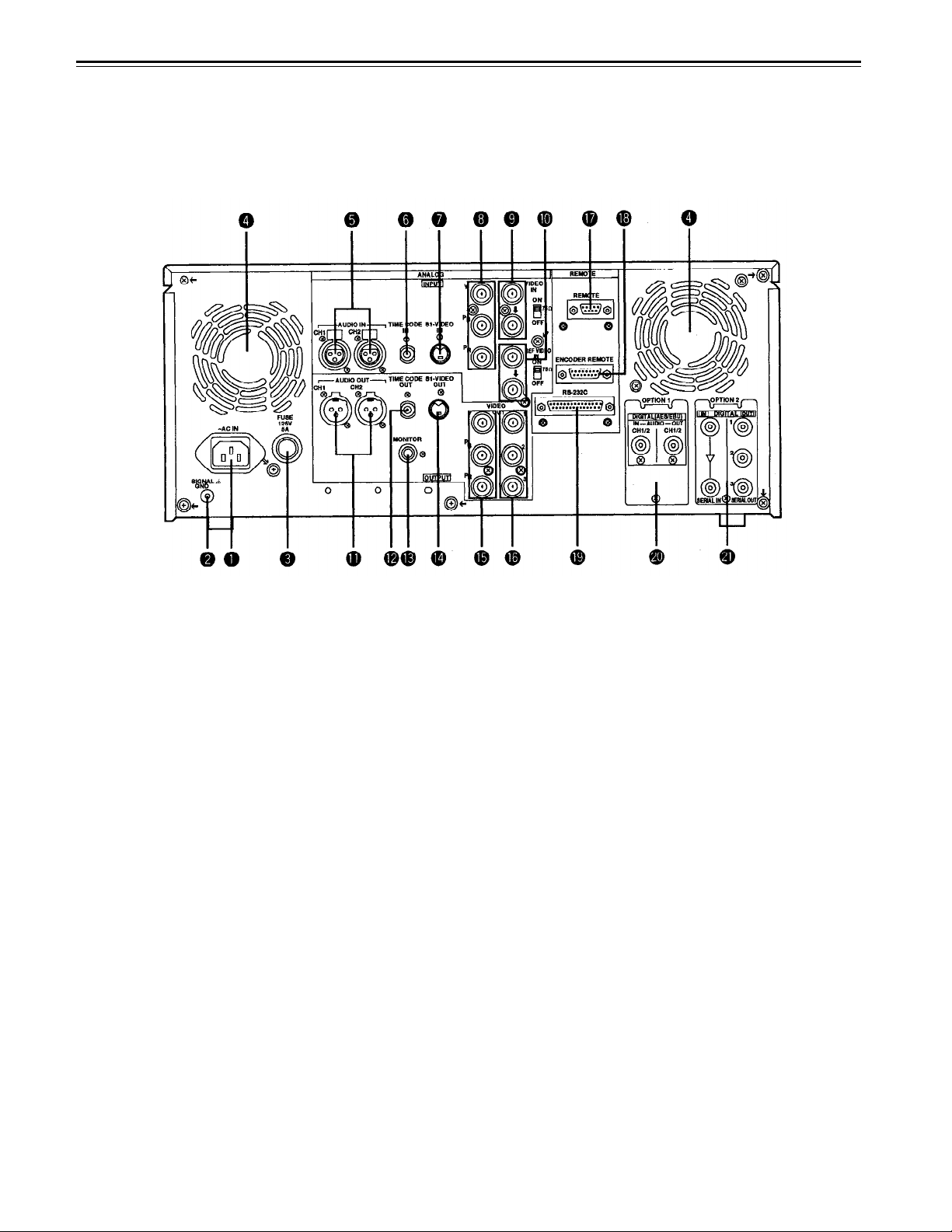
Connector area
–11–

Controls and their functions
(continued)
<Connector area>
AC IN connector
This is for connecting the unit to the power outlet using the power cord provided.
SIGNAL GND terminal
This terminal is connected to the signa unit which is connected to the unit in order to
reduce noise. It is not connected to ground for safety purposes.
Fuse holder
This contains a fuse.
Fan motor
This is for cooling the unit.
The error code is displayed on the counter when trouble has caused the fan motor to
stop. If the unit is still operated in the warning status, the temperature inside the deck will
rise, and when it exceeds the safety temperature, all the unit’s operations will be shut
down.
ANALOG AUDIO IN connectors
These are the analog audio input connectors.
TIME CODE IN connector
This is the connector for recording the external time code on the tape.
S1-VIDEO IN connector
This is the S-VIDEO input connector.
ANALOG COMPONENT VIDEO IN connector
The analog component video signal is supplied to this connector.
Ω Ω
ANALOG COMPOSITE VIDEO IN connectors and 75
The analog composite video signal is supplied to these two connectors which are
connected in a loop-through configuration. When the termination is required, set the
switch to ON.
REF VIDEO IN connectors and 75
These are the input connectors for the reference video signals. When the termination is
required, set the switch to ON.
ANALOG AUDIO OUT connectors
The analog audio signals are output from these connectors.
TIME CODE OUT connector
The playback time code is output from this connector during playback.
During recording, the time code generated by the internal time code generator is output.
MONITOR OUT connector
The playback signals from the CUE track or PCM audio signal CH1/CH2 are output from
this connector.
Ω Ω
termination switch
termination switch
–12–

<Connector
area>
S1/VIDE0 OUT connector
This is the S-VIDEO output connector.
ANALOG COMPONENT VIDEO OUT connector
The analog component video signal is output from this connector.
ANALOG COMPOSITE VIDEO OUT connectors
The analog composite video signals are output from these connectors.
The video signal with signals superimposed on it can be output from the VIDEO OUT3
connector.
The superimpose function can be set ON or OFF on the setup menu No. 006 (SUPER).
REMOTE connector
The unit can be controlled from an external source by connecting an external controller.
ENCODER REMOTE connector
The external encoder/controller is hooked up to this connector when the video output
signal and other settings are to be adjusted from an external source.
RS-232C connector (option)
DIGITAL AUDIO IN/OUT connector (optional AJ-YA655P required.)
This I/O connector is for digital audio signals which comply with the AES/EBU standard.
SERIAL DIGITAL COMPONENT AUDIO/VIDEO IN/OUT connector
(optional AJ-YA750P interface board required)
This I/O connector is for digital component audio and video signals which
SMPTE 259M-C/272M standard.
The optional AJ-YA655P is required for digital audio signal output on the AJ-YA750P
board.
comply with the
–13–
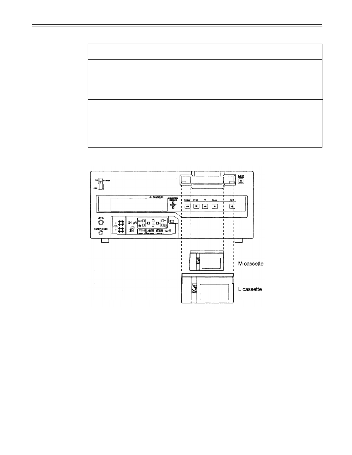
Tapes
Three types of tapes can be used with the unit.
Type
Tape designed exclusively for the camcorders used by consumers in
Consumer
cassette
(S cassette)
M cassette
L cassette
Align the cassette with the center of the insertion slot and push it in gently. The cassette
tape is loaded automatically.
general. Only playback is possible using the optional cassette adaptor.
Use of Panasonic consumer DV cassette tapes is recommended.
Note that inserting a cassette tape without using the cassette adaptor
can damage the unit.
Recording/playback tape with a maximum capacity of 63 minutes.
(AJ-P12MP, AJ-P23MP, AJ-P33MP, AJ-P63MP)
Recording/playback tape with a maximum capacity of 123 minutes.
(AJ-P64LP, AJ-P94LP, AJ-P123LP)
Description
<Notes for playback of consumer DV cassette tape>
• Consumer tapes are for playback only, they cannot be recorded upon by the AJ-D640/AJD650.
• Consumer cassette tapes recorded in LP mode cannot be played back.
• Material recorded on consumer tape must be played back and edited to another
professional VTR.
• The recording functions, recording, Tape/EE and others will not function when Consumer
tape is inserted in the VTR.
• Consumer tape FF/REW speed is VTR limited to ±32×. Slow motion playback is not
possible with consumer cassette tapes.
• In order to protect the tape, the maximum STILL TIMER for consumer tape is 10 seconds,
and the available time for leaving the tape in STILL mode during STEP FWD mode is set
at 1 minute.
• Control (CTL) signals are not displayed when consumer tapes are used. Only the time
code is displayed.
–14–
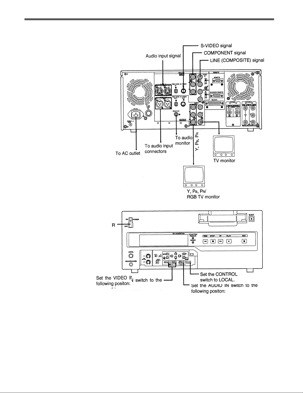
When recording/playback using 1 unit
Set the CONTROL switch on the front panel to LOCAL.
• “DIGITAL” for serial component
digital video signal input.
• Set the VIDEO IN to ANALOG
and select as following for the
analog input:
•
“Y PB PR” for analog
component video signal input.
• “CMPST” for analog composite video signal input.
• “S-VIDEO” for S-VIDEO signal
input.
–15–
• “DIGITAL” for serial component
digital audio signal input.
• “AES/EBU” for digital audio
signal input.
• “ANALOG” for analog audio
signal input.
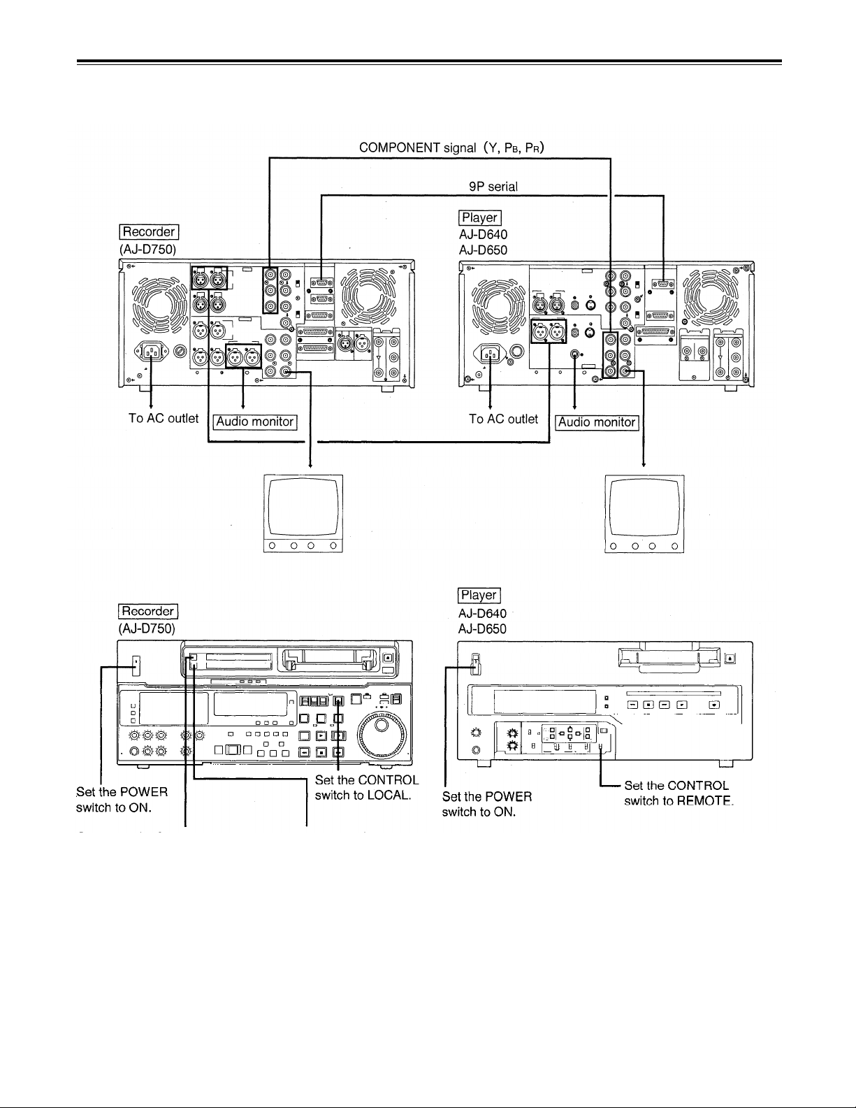
When recording, playback & editing with 2 units (deck to deck)
The CONTROL switch on the recorder must be set to the LOCAL position, and the CONTROL switch on the
player must be set to the REMOTE position.
Set the VIDEO IN switch to the
following position:
• “SERIAL I/F” for serial component digital video signal input.*
• “Y PB PR” for analog compo-
nent video signal input.
• “CMPST” for analog composite
video signal input.
Set the AUDIO IN switch to the
following position:
• “SERIAL l/F” for serial component digital audio signal input.
• “AES/EBU” for digital audio
signal input.
• “ANALOG” for analog audio
signal input.
–16–
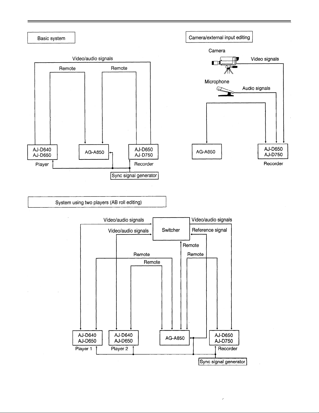
When using an editing controller
For further details, refer to the Operating instructions of the AG-A850 editing controller (optional accessory).
–17–
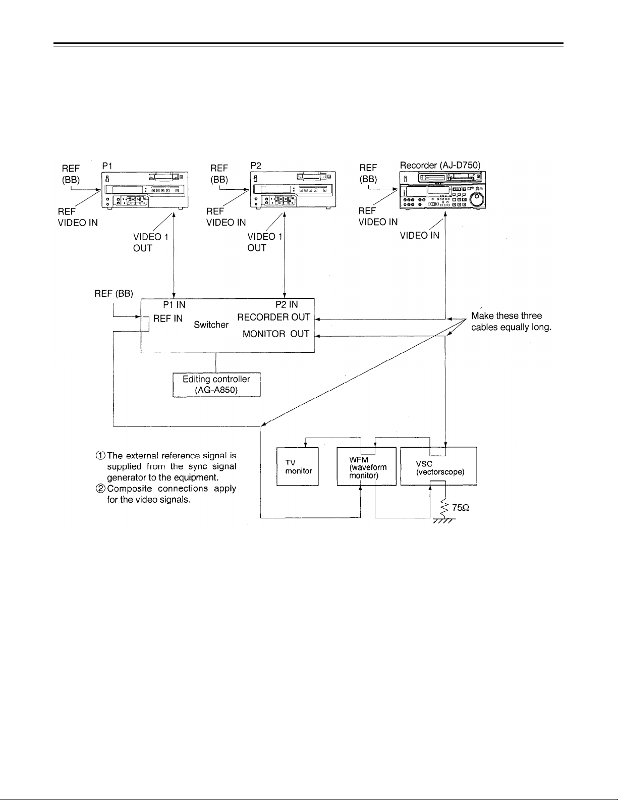
Internal encoder adjustments
In order to ensure error-free and accurate editing during AB roll editing (a method of editing using two source
VTRs) using an editor, the ENCODER OUT controls must be adjusted after the system has been connected.
(These controls must be re-adjusted each time the connecting cables are replaced or the connections are
changed.)
Connect the equipment as shown in the figure below.
If a waveform monitor and vectorscope are not available, correct any color shifting while actually monitoring the
picture on the TV monitor.
–18–
Check the connections. (see previous page.)
Select [OFF] on ENCODER SEL at the set up menu. (See page 27.)
Select [ON] to operate the internal encoder externally.
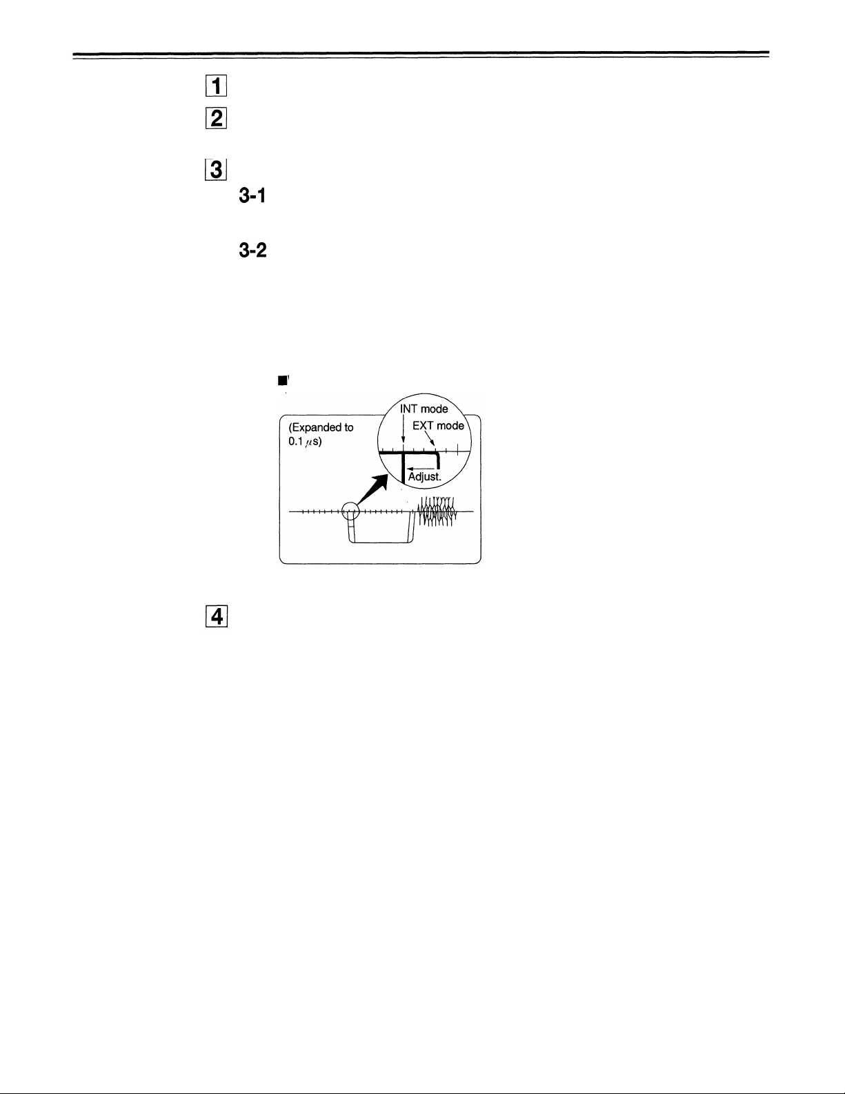
Adjust the SYSTEM PHASE.
On the P1 VTR, play back a cassette tape on which standard color bar signals
have been recorded.
Adjust P1 VTR SYS PHASE.
Adjust the controls to the following with the waveform monitor (WFM).
µ
1) Expand WFM 0.1
2) Check the H SYNC position.
3) In this status, select EXT mode for the WFM.
4) In EXT mode, adjust the SYSTEM PHASE to H, SC COARSE, SC FINE, in
this order, at the set up menu to set H SYNC to its previous position.
Waveform on waveform monitor
s on the INT mode.
(Observe the SYNC fall.)
Adjust the connected P2 VTR in the same way.
–19–
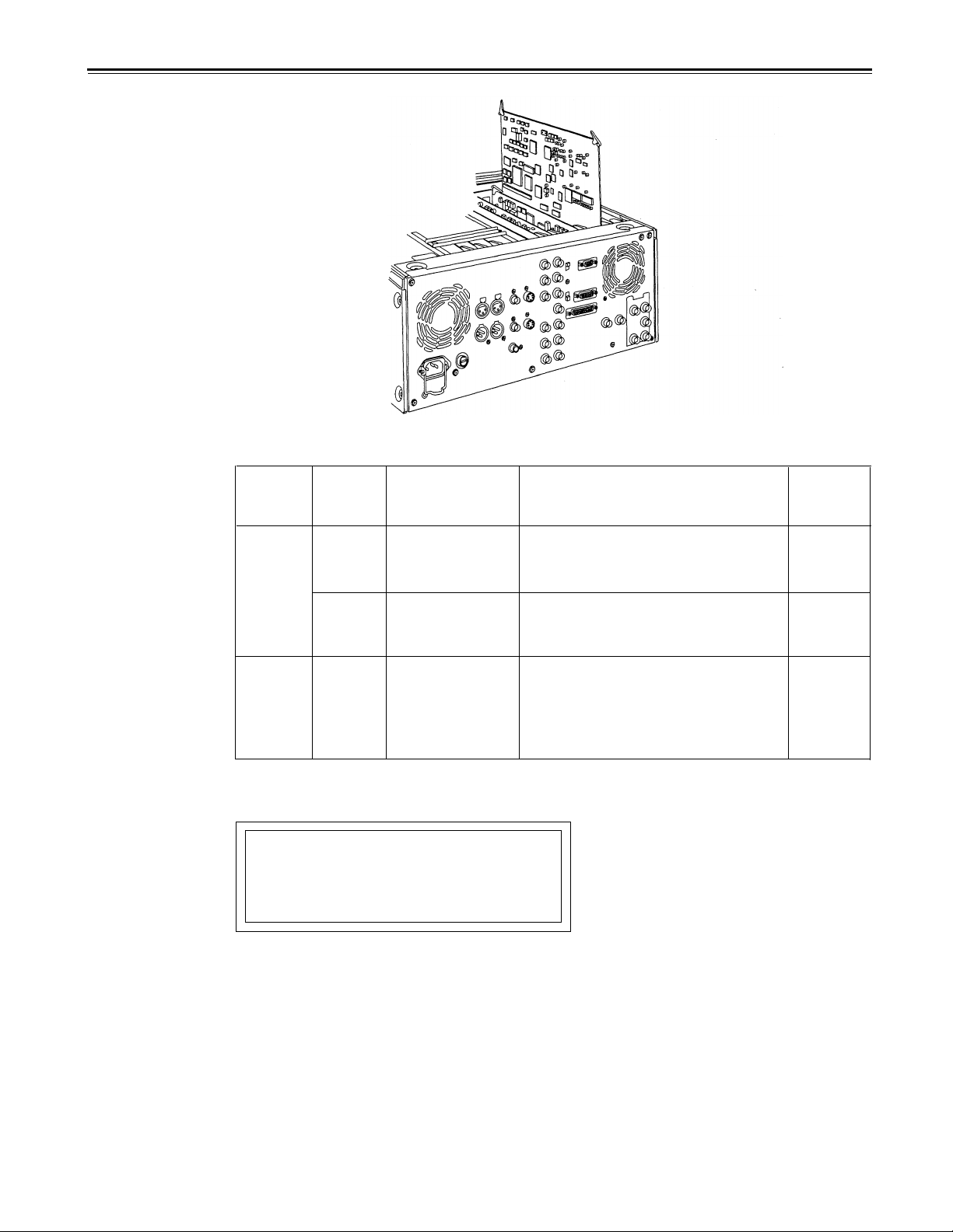
Printed circuit board
Printed
circuit
board
F8 board
ADDA-
CUE
F4 board SW400
<Note>
Component PB/PR input levels are selected at No. 600 in the setup menu.
CAUTION:
TO REDUCE THE RISK OF FIRE OF SHOCK
HAZARD, REFER CHANGE OF SWITCH
SETTING lNSlDE THE UNIT TO AUTHORIZED
SERVICE PERSONNEL.
Abbr.
name
SW1
SW61
Full name
Audio Input
Impedance SW
Audio Input
Impedance SW
Component PB/PR This sets the component PB/PR
Output level
selector the editor.
This sets the CH1 audio input
impedance.
HlGH/600
This sets the CH2 audio input
impedance.
HlGH/600
output level when connecting with
M
ΙΙ
: MΙΙ level
BETA :
Function
Ω
Ω
β
-CAM level
Factory
setting
HIGH
HIGH
BETA
–20–
 Loading...