

Panasonic AG-YA500G Operation Manual
Operating Instructions/Bedienungsanleitung/
Mode d’emploi/Istruzioni per l’uso/
Instrucciones de funcionamiento/
取扱説明書
VF Interface Box/VF Interface Box/
Boîtier d’interface VF/
VF interface box/Interfaz de VF/
VF インターフェースボックス
ModelNo.
Before operating this product, please read the instructions carefully and save this
manual for future use.
Bitte lesen Sie diese Bedienungsanleitung vor der Inbetriebnahme dieses Produkts
aufmerksam durch, und bewahren Sie sie für späteres Nachschlagen auf.
Avant d’utiliser l’appareil, lire attentivement ce mode d’emploi, et le conserver à
des fins de référence ultérieure.
Prima di far funzionare questo prodotto, leggere attentamente le istruzioni e
conservare questo manuale per riferimenti futuri.
Antes de utilizar este producto, lea cuidadosamente las instrucciones y guarde
este manual por si tiene que utilizarlo en el futuro.
このたびは、“ パナソニック製品 ” をお買い上げいただき、まことにありがとうございます。
■ 取扱説明書をよくお読みのうえ、正しく安全にお使いください。
■ ご使 用前に「安全上のご注意」(
■ 保証書は「お買い上げ日・販売店名」などの記入を確かめ、取扱説明書とともに大切に
保管してください。
保証書別添付
AG-YA500G
2 〜 3 ページ)を必ずお読みください。
製造番号は、品質管理上重要なものです。
製品本体と保証書の製造番号をお確かめください。
ENGLISHDEUTSCHITALIANO FRANÇAISESPANÕL
日
本
語
F0909T0 -F @
Printed in Japan
VQT2H48
WARNING:
z To reduce the risk of fire or electric shock, do not expose this equipment
to rain or moisture.
z To reduce the risk of fire or electric shock, keep this equipment away from
all liquids. Use and store only in locations which are not exposed to the
risk of dripping or splashing liquids, and do not place any liquid
containers on top of the equipment.
CAUTION:
To reduce the risk of fire or electric shock and annoying interference, use the
recommended accessories only.
CAUTION:
Do not remove panel covers by unscrewing them.
To reduce the risk of electric shock, do not remove the covers. No user
serviceable parts inside.
Refer servicing to qualified service personnel.
CAUTION:
The mains plug of the power supply cord shall remain readily operable.
The AC receptacle (mains socket outlet) shall be installed near the
equipment and shall be easily accessible. To completely disconnect this
equipment from the AC mains, disconnect the mains plug from the AC
receptacle.
WARNING:
Always keep accessories (screws) out of the reach of babies and small
children.
English
Read this first!
indicates safety information.
EEE Yönetmeliğine Uygundur.
EEE Complies with Directive of Turkey.
E-1
Read this first! (Continued)
FCC Note (USA):
This equipment has been tested and found to comply with the limits for a class B digital
device, pursuant to Part 15 of the FCC Rules. These limits are designed to provide
reasonable protection against harmful interference in a residential installation. This
equipment generates, uses, and can radiate radio frequency energy and, if not installed
and used in accordance with the instruction manual, may cause harmful interference to
radio communications. However, there is no guarantee that interference will not occur
in a particular installation. If this equipment does cause harmful interference to radio or
television reception, which can be determined by turning the equipment off and on, the
user is encouraged to try to correct the interference by one or more of the following
measures:
z Reorient or relocate the receiving antenna.
z Increase the separation between the equipment and receiver.
z Connect the equipment into an outlet on a circuit different from that to which the
receiver is connected.
z Consult the dealer or an experienced radio/TV technician for help.
z The user may find the booklet “Something About Interference” available from FCC
local regional offices helpfu l.
Warning :
To assure continued FCC emission limit compliance, follow the attached installation
instructions and the user must use only shielded interface cables when connecting to
peripheral devices. Also any unauthorized changes or modifications to this equipment
could void the user’s authority to operate this device.
NOTIFICATION (Canada)
This class B digital apparatus complies with Canadian ICES-003.
indicates safety information.
ENGLISH
E-2

Read this first ! (continued)
EMC NOTICE FOR THE PURCHASER/USER OF THE APPARATUS
1. Applicable standards and operating environment (For Europe)
The apparatus is compliant with:
z standards EN55103-1 and EN55103-2 1996.11, and
z electromagnetic environments E1, E2, E3, and E4.
2.
Pre-requisite conditions to achieving compliance with the above standards
<1> Peripheral equipment to be connected to the apparatus and special
connecting cables
z The purchaser/user is urged to use only equipment which has been recommended by
us as peripheral equipment to be connected to the apparatus.
z The purchaser/user is urged to use only the connecting cables described below.
<2> For the connecting cables, use shielded cables which suit the intended
purpose of the apparatus.
z Video signal connecting cables
Use double shielded coaxial cables, which are designed for 75-ohm type highfrequency applications, for SDI (Serial Digital Interface).
Coaxial cables, which are designed for 75-ohm type high-frequency applications, are
recommended for analog video signals.
z Audio signal connecting cables
If your apparatus supports AES/EBU serial digital audio signals, use cables designed for AES/EBU.
Use shielded cables, which provide quality performance for high-frequency
transmission applications, for analog audio signals.
z Other connecting cables (IEEE1394, USB)
Use shielded cables, which provide quality performance for high-frequency
applications, as connecting cables.
z When connecting to the DVI signal terminal, use a cable with a ferrite core.
z If your apparatus is supplied with ferrite core(s), they must be attached on cable(s)
following instructions in this manual.
3. Performance level
The performance level of the apparatus is equivalent to or better than the performance level
required by these standards.
However, the apparatus may be adversely affected by interference if it is being used in an EMC
environment, such as an area where strong electromagnetic fields are generated (by the
presence of signal transmission towers, cellular phones, etc.). In order to minimize the adverse
effects of the interference on the apparatus in cases like this, it is recommended that the
following steps be taken with the apparatus being affected and with its operating environment:
1. Place the apparatus at a distance from the source of the interference.
2. Change the direction of the apparatus.
3. Change the connection method used for the apparatus.
4. Connect the apparatus to another power outlet where the power is not shared by any
other appliances.
E-3
Thank you for purchasing the VF Interface Box AG-YA500G (“this unit” hereafter).
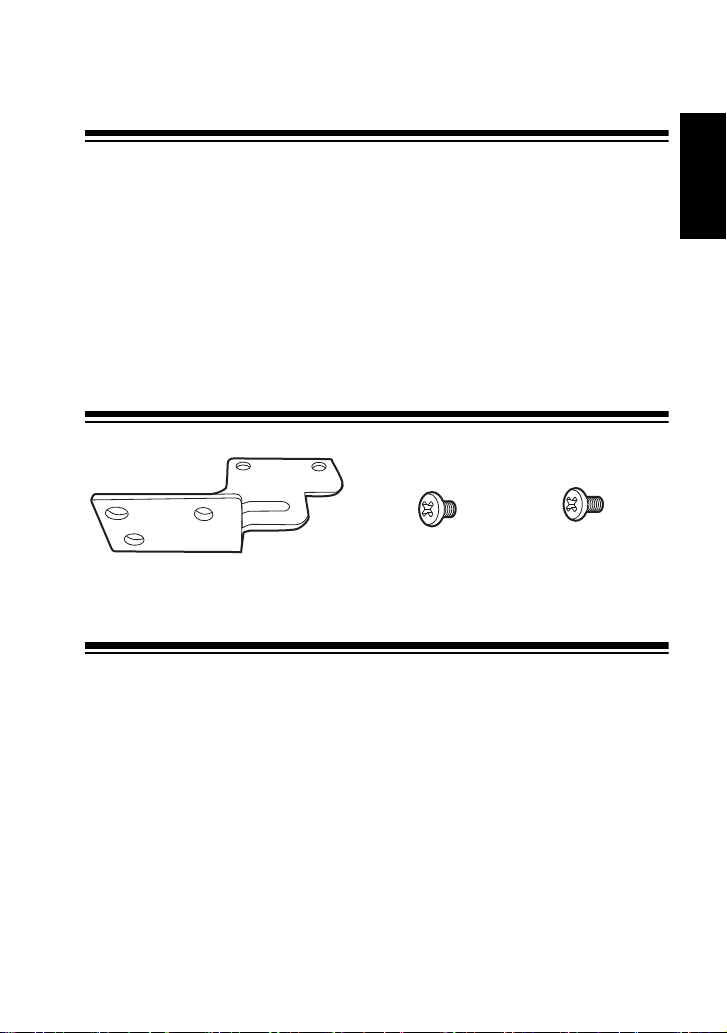
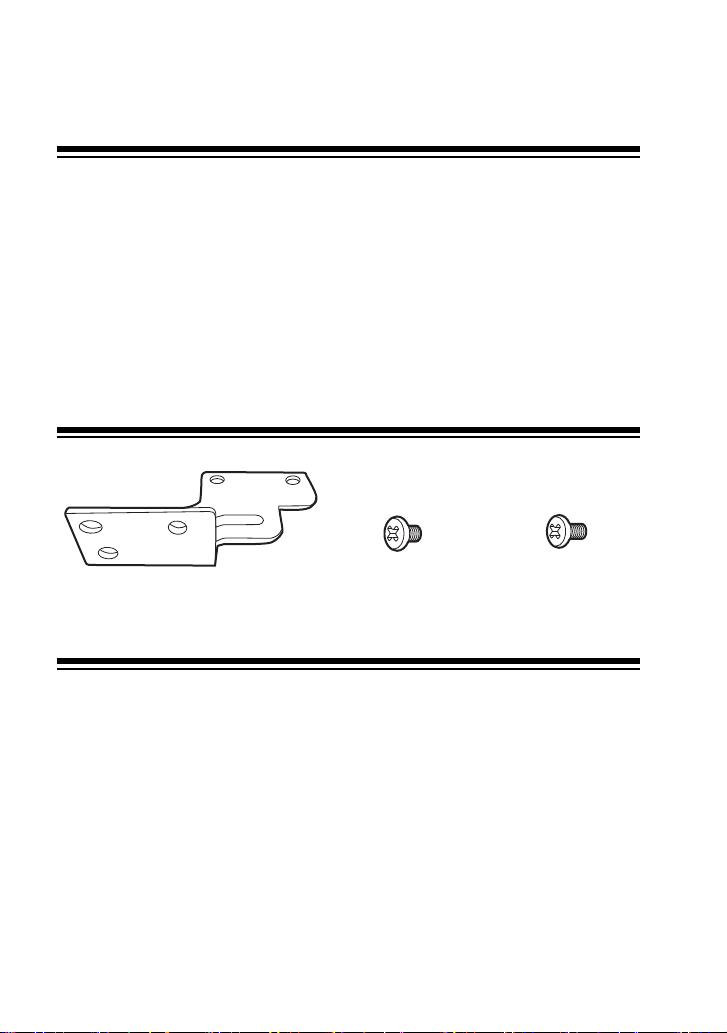
Mounting bracket a 1
Mounting screws
(8 mm) a 4
Mounting screws
(12 mm) a 2
Contents
Read this first! ................................................................................. E-1
Supplied Accessories ..................................................................... E-4
Features ........................................................................................... E-4
System Diagram .............................................................................. E-5
Parts and their functions ................................................................ E-6
Mounting to the Camera recorder.................................................. E-7
Basic Operations ............................................................................. E-8
Specifications .................................................................................. E-10
Supplied Accessories
Features
ENGLISH
z This unit switches the video signal output from the VF connector of the camera recorder that
is recording with the return video (RET video) output from the camera adapter (AG-CA300G,
optional), and supplies it to the viewfinder.
z Switching of the signal can be performed by the RET switch on the lens or the RET switch
on the camera adapter.
z It is possible to turn on the tally of the viewfinder if there is a tally signal output from either
the camera recorder or the camera adapter.
E-4
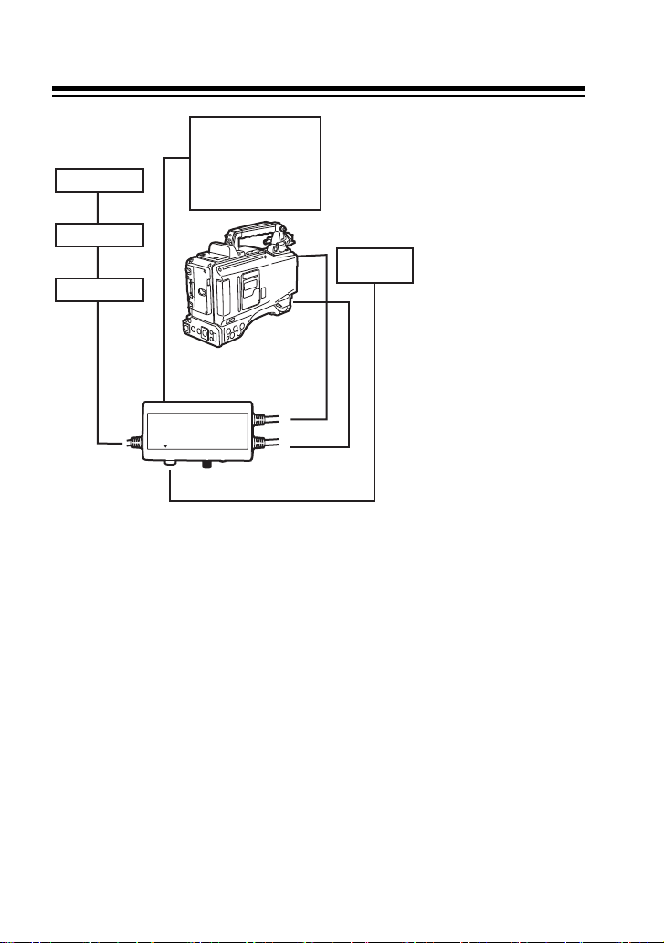
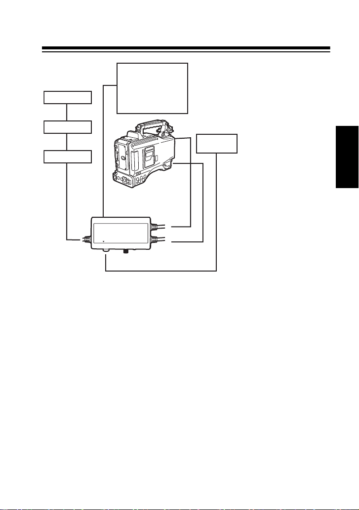
System Diagram
CA VF
LENS
CAM LENS
CAM VF
AG-YA500G
Viewfinder
AJ-VF15BP/E
AJ-VF20WBP/E
AG-VF11G
AJ-HVF21G
AJ-CVF100G
Lens
AG-CA300G
AG-BS300P/E
AG-EC4G
Camera recorder *
* Compatible camera recorders
AG-HPX500/502
AJ-HPX3700G
AJ-HPX2700G
AJ-HPX3000G
AJ-HPX2000/2100
AJ-HDX900P/E
<Notes>
z This unit needs to set the viewfinder type (HD/ LCD SD) connected via the menu of the base
station (AG-BS300P/E, option). Refer to the operating Instructions of the AG-BS300P/E.
z Connect all the connectors on this unit to the camera recorder, lens, camera adapter and the
viewfinder.
z When storing the camera recorder into the hard carrying case, remove this unit from the
camera recorder before storing.
z Only lenses that have a round 12-pin connector interface are compatible with this unit.
E-5
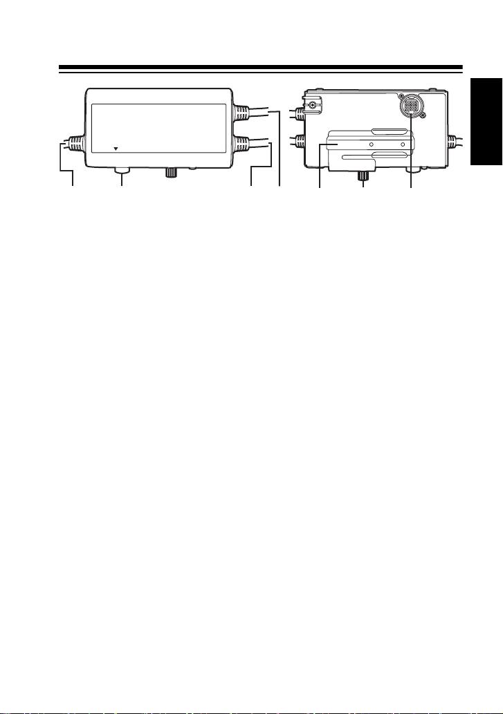
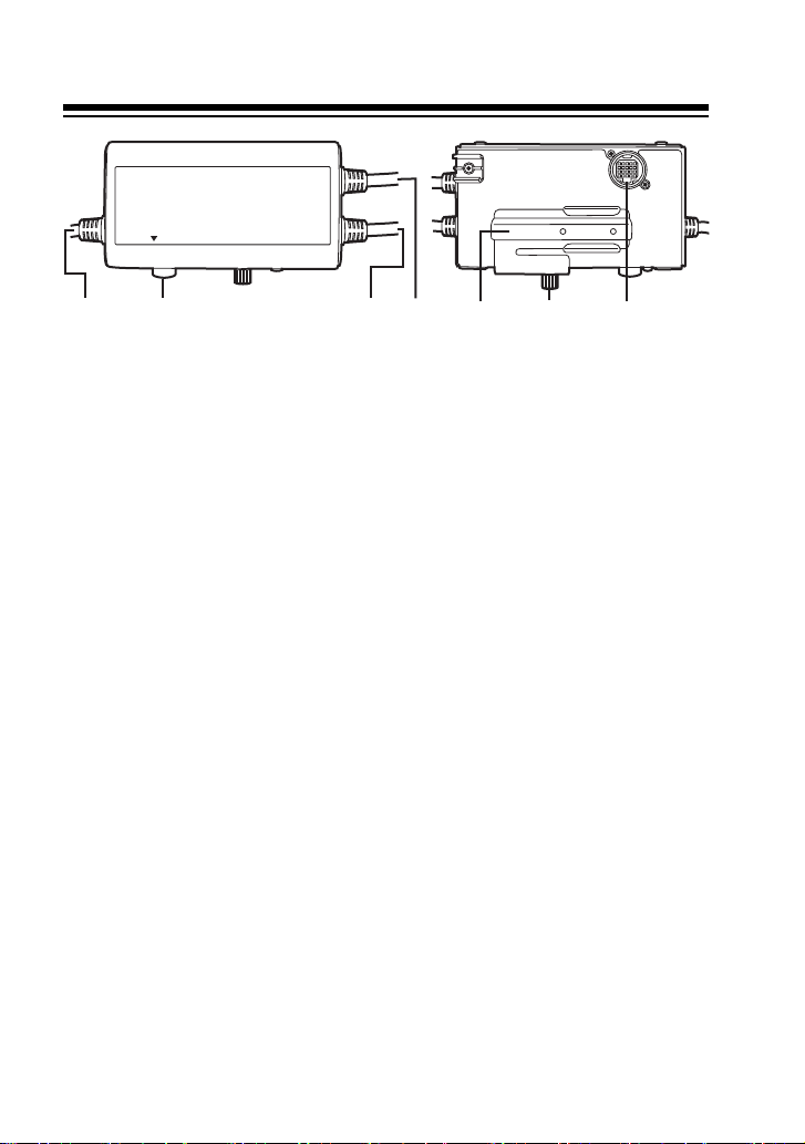
Parts and their functions
VF
6
5
7
CA VF
LENS
CAM LENS
CAM VF
1
3
2
4
1. LENS connector (12 pins)
This is a connector to input the signal from
the lens. Connect with the connector on
the lens.
2. CAM LENS c
This is a connector to output the signal
from the lens to the camera recorder.
Connect with the lens connector of the
camera recorder.
3. CAM VF c
This is a connector to input the signal from
the camera recorder. Connect with the VF
connector of the camera recorder.
4. CA VF c
This is a connector to receive the return
video (RET video) and the tally signal from
the camera adapter. Connect with the VF
OUT connector of the camera adapter.
5. VF connector
This is a connector to output the video
signal and tally signal switched by this
unit. Connect with the viewfinder.
6. Adjustment screw
This is used to adjust this unit backward
and forward to match the viewfinder in
use.
7. Adjustment bracket
Attach the included mounting bracket.
After checking "Mounting to the Camera
recorder" (page 7), attach to the
adjustment bracket and the camera
recorder.
able
able
able
ENGLISH
E-6
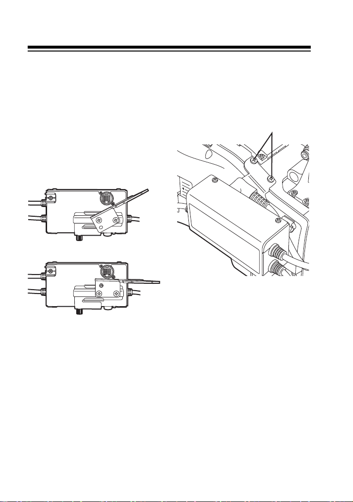
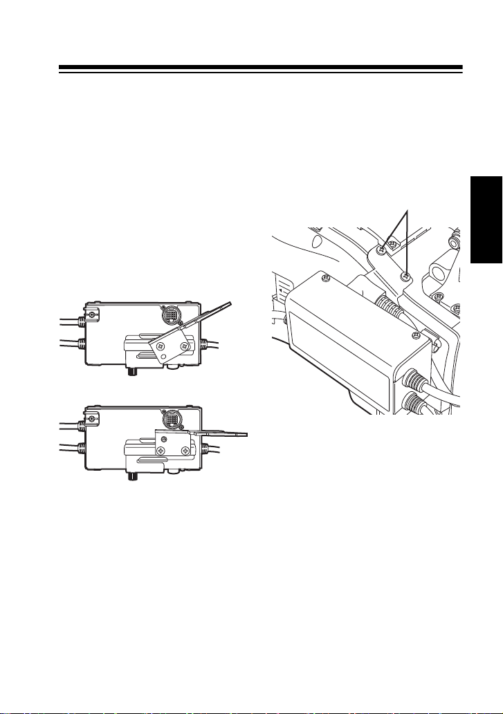
Mounting to the Camera recorder
Mounting screws
1 Confirm the supplied accessories.
2 Mount the mounting bracket to the
adjustment bracket using the two
included mounting screws (8 mm) so
that this unit will be horizontal when it is
mounted to the camera recorder to be
used.
Note that the position of the mounting
bracket varies as shown below
depending on the model of camera
recorder in use.
AJ-HPX2700G/AJ-HPX3700G
AJ-HPX2000P/2100E/AJ-HPX3000G
AG-HPX500/502
AJ-HDX900P/E
3 Mount the mounting bracket to the
camera recorder using the two included
(8 mm) mounting screws.
When using the microphone holder
(AJ-MH800G, optional) together with this
unit, use the included mounting screws
(12 mm).
4 Connect the camera recorder and
camera adapter to this unit referring to
“Parts and their functions” (page 6).
E-7
Basic Operations
z Switching of the video signals is performed by pressing the RET switch on the lens or the
RET switch on the camera adapter. Return video is output from this unit while the RET
switch is pressed.
Also, if there is a tally signal either from the camera recorder or the base station, it is also
output from this unit, and the tally LED on the viewfinder can be turned on. However, the tally
LED on the camera adapter is turned on only by the tally signal from the base station.
z With the system combining the base station and the camera adapter, it is possible to select
the HD or SD video signal as a return video.
If the system is HD, either HD or SD return video can be selected.
If the system is SD, the return video will only be SD video signal.
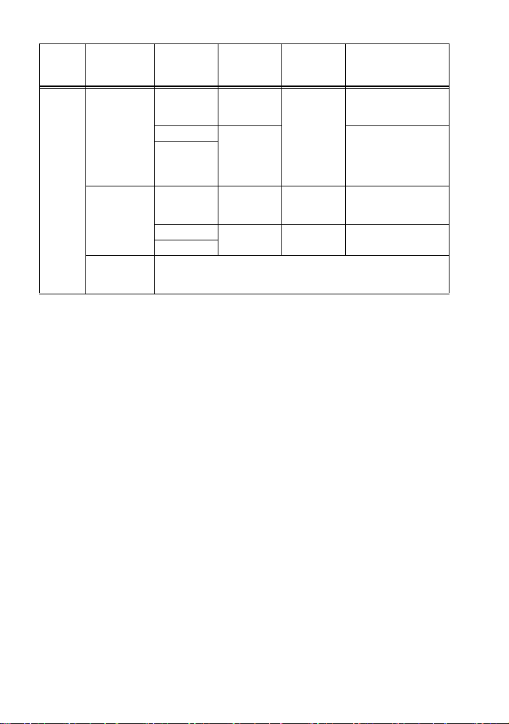
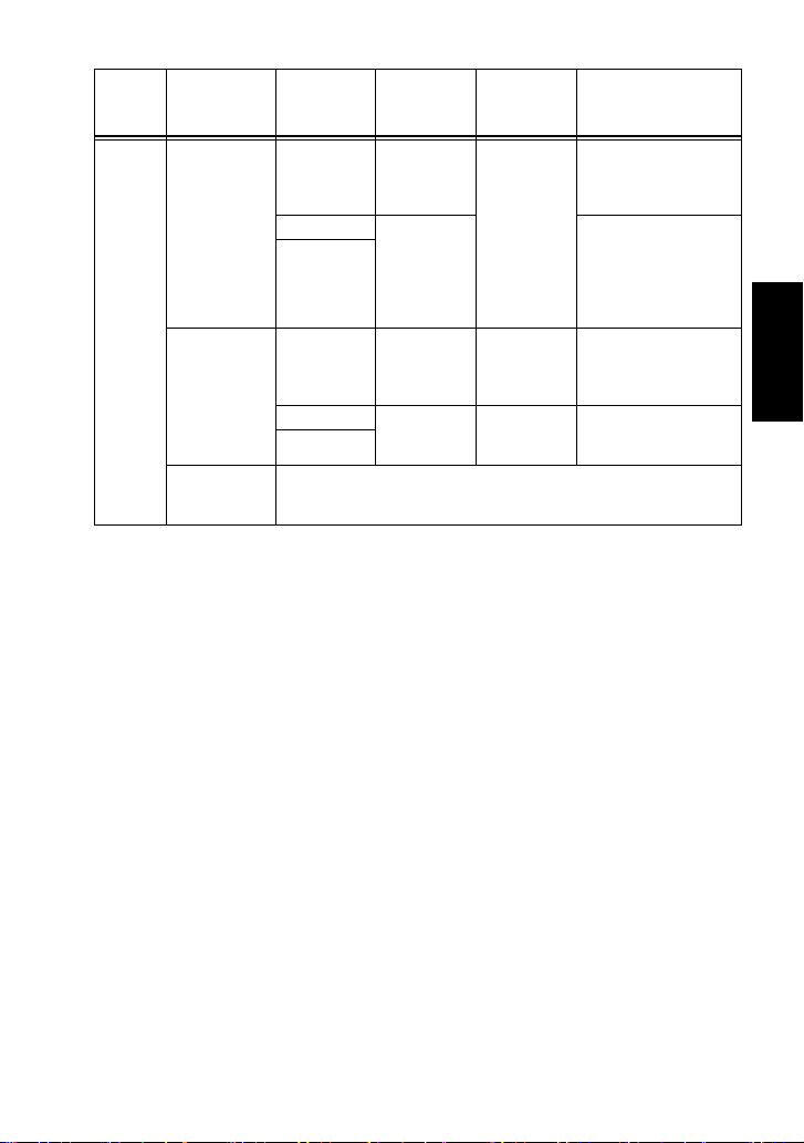
The camera system (HD/SD), return video (HD/SD), and the viewfinder can be used in the
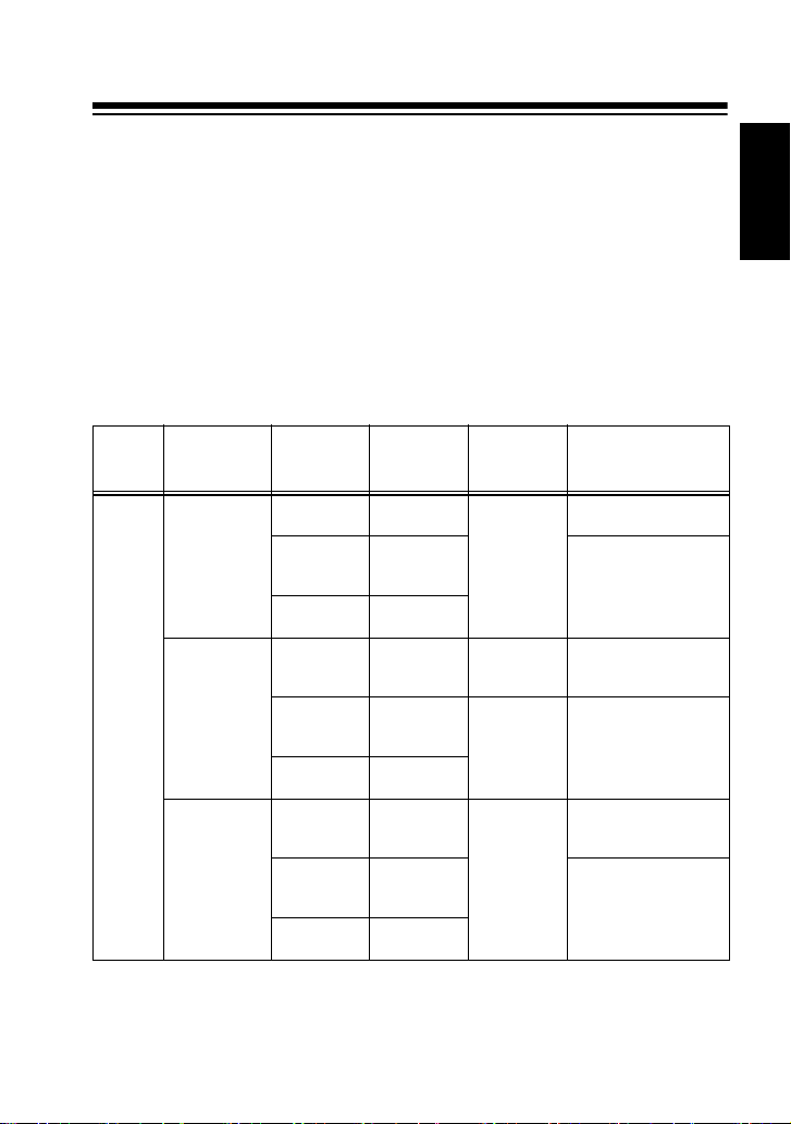
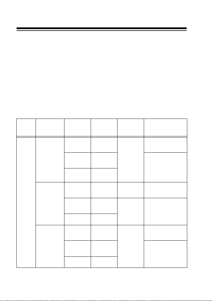
following combinations:
RET signal switching when this unit is used
(Connected viewfinder: AJ-HVF21G / AJ-VF11G / Viewfinder included with
System Camera model
AG-HPX500/
502
AJ-HPX3000G*
unit menu.
AJ-HPX2000P/
2100E*
AJ-HPX3700G
AJ-HPX2700G
AJ-HDX900P/E
HD
* You can switch between camera recorder VF connector signals using the camera recorder
the AG-HPX500/502 / AJ-CVF100G)
RET input signal
format to the AG-
BS300P/E
HD SDI
SD SDI
COMPOSITE
HD SDI
AG-CA300G
VF OUT
connector
signal
HD
COMPONENT
SD SDI
cannot be
transmitted.
SD
COMPONENT
HD
COMPONENT
Camera
recorder VF
connector
signal
SD
COMPONENT
HD
COMPONENT
SD SDI
SD SDI
COMPOSITE
HD SDI
SD SDI
COMPOSITE
cannot be
transmitted.
SD
COMPONENT
HD
COMPONENT
SD SDI
cannot be
transmitted.
SD
COMPONENT
SD
COMPONENT
HD
COMPONENT
Image displayed on the
AJ-HVF21G/AG-VF11G/
AJ-CVF100G
Cannot be used since
HD/SD are mixed.
SD COMPONENT
(AG-VF11G can be used)
(Viewfinder included
with the AG-HPX500/
502 can be used)
HD COMPONENT
(AJ-HVF21G/AJ-CVF100G
can be used)
SD COMPONENT
(AG-VF11G can be used)
HD COMPONENT
(AJ-HVF21G/AJ-CVF100G
can be used)
Cannot be used since
HD/SD are mixed.
ENGLISH
E-8
System Camera model
AG-HPX500/
502
SD
AJ-HPX3000G*
AJ-HPX2000P/
2100E*
AJ-HPX3700G
AJ-HPX2700G
RET input signal
format to the AG-
BS300P/E
AG-CA300G
VF OUT
connector
signal
HD SDI
HD SDI
cannot be
transmitted.
SD SDI
SD
COMPOSITE
COMPONENT
HD SDI
HD SDI
cannot be
transmitted.
SD SDI
COMPOSITE
SD
COMPONENT
Cannot use since system cannot be set to SD mode.
Camera
recorder VF
connector
signal
SD
COMPONENT
HD
COMPONENT
SD
COMPONENT
Imag e displayed on the
AJ-HVF21G/AG-VF11G/
AJ-CVF100G
Cannot use since HD
video cannot be
transmitted.
SD COMPONENT
(AG-VF11G can be used)
(Viewfinder included
with the AG-HPX500/
502 can be used)
Cannot use since HD
video cannot be
transmitted.
SD COMPONENT
(AG-VF11G can be used)
AJ-HDX900P/E
* You can switch between camera recorder VF connector signals using the camera recorder
unit menu.
<Note>
AJ-VF15BP/E and AJ-VF20WBP/E will have same operation as the AG-VF11G. Note that the
AJ-VF15BP/E and the AJ-VF20WBP/E do not support automatic switching between field
frequencies of 59.94 (60) Hz/50 Hz. Select a viewfinder to match the field frequency that is in
use.
E-9
Specifications
[General]
Input
DC + 5.6 V, 0.06 A
DC - 5.6 V, 0.06 A
indicates safety information.
Dimensions (W a H a D):
113 mm a 60 mm a 41 mm
(4.4 inches a 2.4 inches a 1.6 inches)
(excluding protruding parts)
Weight:
approx. 410 g (approx. 0.9 lb)
Operating temperature:
0 °C to 40 °C (32 °F to 104 °F)
Storage temperature:
-20 °C to 60 °C (-4 °F to 140 °F)
Operating humidity:
10 % to 85 % (w/o condensation)
Information on Disposal for Users of Waste Electrical & Electronic Equipment (private
households)
your local authority for further details of your nearest designated collection point.
Penalties may be applicable for incorrect disposal of this waste, in accordance with national
legislation.
For business users in the European Union
If you wish to discard electrical and electronic equipment, please contact your dealer or
supplier for further information.
Information on Disposal in other Countries outside the European Union
This symbol is only valid in the European Union.
If you wish to discard this product, please contact your local authorities or dealer and ask for
the correct method of disposal.
This symbol on the products and/or accompanying documents means that used
electrical and electronic products should not be mixed with general household
waste.
For proper treatment, recovery and recycling, please take these products to
designated collection points,where they will be accepted on a free of charge
basis. Alternatively, in some countries you may be able to return your products to
your local retailer upon the purchase of an equivalent new product.
Disposing of this product correctly will help to save valuable resources and
prevent any potential negative effects on human health and the environment
which could otherwise arise from inappropriate waste handling. Please contact
[I/O Section]
LENS:
Round 12 pin
CAM LENS:
Round 12 pin
CAM VF:
Round 20 pin
VF:
Round 20 pin
CA VF:
D-Sub 15 pin
[Accessories]
Mounting bracket a 1
Mounting screws (8 mm) a 4
Mounting screws (12 mm) a 2
Weight and dimensions when shown are
approximately. Specifications are subject to
change without notice.
ENGLISH
E-10
WARNUNG:
z Zur Reduzierung der Gefahr eines Brands oder elektrischen Schlags
dieses Gerät weder Nässe noch Feuchtigkeit aussetzen.
z Zur Reduzierung der Gefahr eines Brands oder elektrischen Schlags
muss dieses Gerät von allen Flüssigkeiten ferngehalten werden.
Vermeiden Sie Gebrauch und Lagerung des Gerätes an orten, an denen
die Gefahr besteht, dass es mit Flüssigkeiten betropft oder bespritzt wird,
und stellen Sie keine Flüssigkeitsbehälter auf das Gerät.
VORSICHT:
Nur das empfohlene Zubehör verwenden, um die Gefahr von Feuer und
elektrischem Schlag sowie Störungen auszuschalten.
WARNUNG:
Öffnen Sie nicht das Gerät durch Abschrauben von Gehäuseteilen.
Zur Vermeidung von elektrischem Schlag darf das Gehäuse nicht geöffnet
werden. Im Geräteinneren befinden sich keine Teile, die vom Benutzer
gewartet werden können.
Wartungs- und Reparaturarbeiten grundsätzlich autorisiertem
Kundendienstpersonal überlassen.
VORSICHT:
Ein unbehinderter zugang zum Netzstecker des Netzkabels muss jederzeit
gewährleistet sein.
Die Steckdose (Netzsteckdose) sollte in der nähe des Gerätes installiert
werden und leicht zugänglich sein.
Um dieses Gerät vollständig vom Nets zu trennen, den Netzstecker aus der
Netzsteckdose ziehen.
WARNUNG:
Halten Sie Zubehörteile (Schrauben) stets fern von Babys und Kleinkindern.
GERMAN
Bitte lesen!
G-1
ist die Sicherheitsinformation.

Bitte lesen ! (Fortsetzung)
EMV-HINWEIS FÜR DEN KÄUFER/ANWENDER DES GERÄTS
1. Anwendbare Standards und Betriebsumgebung (Für Europe)
Dieses Gerät entspricht:
z Standards EN55103-1 und EN55103-2 1996.11 und
z elektromagnetische Umgebungen, E1, E2, E3 und E4.
2.
Erforderliche Bedingungen zur Einhaltung der oben genannten Standards
<1> An das Gerät angeschlossene Geräte und spezielle Verbindungskabel
z Der Käufer/Anwender sollte nur Geräte verwenden, die von uns als Zusatzgeräte für
den Anschluss an das Gerät empfohlen wurden.
z Der Käufer/Anwender sollte nur die unten aufgeführten Verbindungskabel verwenden.
<2> Für den Anschluss abgeschirmte Kabel verwenden, die dem Gerätezweck
entsprechen
z Videokabel
Für SDI (Serial Digital Interface) doppelt abgeschirmte 75-Ohm HF-Koaxialkabel
verwenden.
Für analoge Videosignale werden 75-Ohm HF-Koaxialkabel empfohlen.
z Audiokabel
Verwenden Sie Kabel für AES/EBU, wenn Ihr Gerät serielle digitale AES/EBUAudiosignale unterstützt.
Verwenden Sie für analoge Audiosignale abgeschirmte Kabel für hochwertige HFÜbertragungen.
z Weitere Kabel (IEEE1394, USB)
Verwenden Sie abgeschirmte Kabel für hochwertige HF-Anwendungen.
z Für die Verbindung zum DVI-Signalanschluss muss ein Kabel mit Ferritkern verwendet
werden.
Wird Ihr Gerät mit Ferritkernen geliefert, müssen diese an den Kabeln befestigt werden, siehe
z
Angaben in dieser Anleitung.
3. Leistungsniveau
Das Leistungsniveau des Geräts entspricht oder übersteigt das von diesen Standards verlangte
Leistungsniveau.
Das Gerät kann aber durch Nutzung in einer EMV-Umgebung, wie Bereichen mit starken
elektromagnetischen Feldern (durch Sendemasten, Mobiltelefone etc.) störend beeinflusst
werden. Um in diesen Situationen die störenden Einflüsse auf das Gerät zu minimieren wird
empfohlen, folgende Schritte für betroffene Geräte und Betriebsumgebungen durchzuführen.
1. Positionieren Sie das Gerät von der Störquelle entfernt.
2. Ändern Sie die Geräterichtung.
3. Ändern Sie die Anschlussmethode des Geräts.
4. Schließen Sie das Gerät an eine andere Stromverbindung, die mit keinen weiteren
Geräten geteilt wird.
DEUTSCH
G-2
Vielen Dank, dass Sie die VF Interface Box AG-YA500G gekauft haben (nachfolgend “dieses
Montageklammer a 1
Montageschrauben
(8 mm) a 4
Montageschrauben
(12 mm) a 2
Gerät”).
Inhalt
Bitte lesen!........................................................................................G-1
Mitgeliefertes Zubehör.....................................................................G-3
Funktionen........................................................................................G-3
System Diagram ...............................................................................G-4
Teile und ihre Funktionen................................................................G-5
Montage an den Kamerarecorder ...................................................G-6
Basisbetrieb......................................................................................G-7
Spezifikationen .................................................................................G-9
Mitgeliefertes Zubehör
Funktionen
z Dieses Gerät schaltet die Videosignalausgabe vom VF-Anschluss des Kamerarecorders
um, welcher mit der Return-Video-Ausgabe (RET Video) vom Kameraadapter (AG-CA300G,
optional) aufnimmt, und liefert es an den Sucher.
z Das Ausschalten des Signals kann mit dem RET-Schalter am Objektiv oder mit dem RET-
Schalter am Kameraadapter durchgeführt werden.
z Es ist möglich, den Zähler des Suchers einzuschalten, wenn es entweder vom
Kamerarecorder oder vom Kameraadapter eine Zählerausgabe gibt.
G-3
CA VF
LENS
CAM LENS
CAM VF
AG-YA500G
Sucher
AJ-VF15BP/E
AJ-VF20WBP/E
AG-VF11G
AJ-HVF21G
AJ-CVF100G
Objektiv
AG-CA300G
AG-BS300E
AG-EC4G
Kamerarecorder *
* Kompatible Kamerarecorder
AG-HPX500E
AJ-HPX3700G
AJ-HPX2700G
AJ-HPX3000G
AJ-HPX2100E
AJ-HDX900E
System Diagram
<Hinweise>
z Dieses Gerät muss den Suchertyp (HD/LCD SD) einstellen, der durch das Menü der
Basisstation (AG-BS300E, optional) verbunden wird. Siehe Gebrauchsanweisung des AGBS300E.
z Verbinden Sie die Anschlüsse dieses Geräts mit dem Kamerarecorder, Objektiv,
z Wenn Sie den Kamerarecorder in der Hartschalentragetasche aufbewahren, montieren Sie
z Nur Objektive mit einer runden 12-poligen Anschlussschnittstelle sind mit diesem Gerat
Kameraadapter und dem Sucher.
dieses Gerät vom Kamerarecorder ab, bevor Sie es aufbewahren.
kompatibel.
DEUTSCH
G-4
Teile und ihre Funktionen
VF
6
5
7
CA VF
LENS
CAM LENS
CAM VF
1
3
2
4
1. LENS-Anschluss (12 Kontakte)
Dies ist ein Anschluss, um das Signal vom
Objektiv einzuspeisen. Schließen Sie ihn
an den Anschluss des Objektivs an.
2. CAM LENS-Kabel
Dies ist ein Anschluss, um das Signal vom
Objektiv an den Kamerarecorder
auszugeben. Schließen Sie ihn an den
Objektivanschluss des Kamerarecorders
an.
3. CAM VF-Kabel
Dies ist ein Anschluss, um das Signal vom
Kamerarecorder einzuspeisen. Schließen
Sie ihn an den VF-Anschluss des
Kamerarecorders an.
4. CA VF-Kabel
Dies ist ein Anschluss, um das ReturnVideo-Signal (RET Video) und das
Zählersignal vom Kameraadapter zu
erhalten. Verbinden Sie ihn mit dem VF
OUT-Anschluss des Kameraadapters.
5. VF-Anschluss
Dies ist ein Anschluss, um das
Videosignal und das Zählersignal
auszugeben, welches von diesem Gerät
umgeschaltet wird. Schließen Sie es an
den Sucher an.
6. Justierschraube
Diese wird verwendet, um dieses Gerät
vorwärts und rückwärts zu justieren, damit
es mit dem Sucher, wenn er im Gebrauch
ist, übereinstimmt.
7. Justierklammer
Bringen Sie die beigelegte
Montageklammer an.
Nachdem Sie “Montage an den
Kamerarecorder” (Seite 6), gelesen
haben, bringen Sie sie an der
Justierklammer und dem Kamerarecorder
an.
G-5
Montage an den Kamerarecorder
Montageschrauben
1 Bestätigen Sie das Mitgeliefertes
Zubehör.
2 Montieren Sie die Montageklammer an
die Justierklammer, indem Sie die zwei
mitgelieferten Montageschrauben (8
mm) verwenden, sodass dieses Gerat
horizontal ausgerichtet ist, wenn es am
Kamerarecorder angebracht wird, der
verwendet werden soll.
Beachten Sie, dass die Position der
Montageklammer, je nachdem welches
Modell des Kamerarecorders in
Gebrauch ist, variieren kann, wie unten
gezeigt wird.
AJ-HPX2700G/AJ-HPX3700G
AJ-HPX2100E/AJ-HPX3000G
AG-HPX500E
AJ-HDX900E
3 Montieren Sie die Montageklammer an
den Kamerarecorder, indem Sie die
zwei mitgelieferten Montageschrauben
(8 mm) verwenden.
Wenn Sie den Mikrofonhalter
(AJ-MH800G, optional) zusammen mit
diesem Gerät verwenden, verwenden
Sie die mitgelieferten
Montageschrauben (12 mm).
4 Schließen Sie den Kamerarecorder und
den Kameraadapter an dieses Gerät an,
indem Sie sich “Teile und ihre
Funktionen” (Seite 5) ansehen.
DEUTSCH
G-6
Basisbetrieb
z Das Ausschalten des Videosignals wird durch das Drücken des RET-Schalters am Objektiv
oder des RET-Schalters am Kameraadapter durchgeführt. Return Video wird von diesem
Gerät ausgegeben, während der RET-Schalter gedrückt wird.
Es wird auch von diesem Gerät ausgegeben, wenn es ein Zählersignal, entweder vom
Kamerarecorder oder der Basisstation, gibt und die Zähler-LED-Anzeige am Sucher
eingeschaltet werden kann. Allerdings wird die Zähler-LED-Anzeige am Kameraadapter nur
durch das Zählersignal der Basisstation eingeschaltet.
z Da das System die Basisstation mit dem Kameraadapter kombiniert, ist es möglich das HD
oder das SD-Videosignal als Videorücklauf auszuwählen.
Wenn das System HD ist, kann entweder HD oder SD Return Video gewählt werden.
Wenn das System SD ist, ist das Return Video nur ein SD-Videosignal.
Das Kamerasystem (HD/SD), Return Video (HD/SD) und der Sucher, können in folgenden
Kombinationen verwendet werden:
RET-Signal umschalten, wenn dieses Gerät verwendet wird
(Angeschlossener Sucher: AJ-HVF21G / AJ-VF11G / Mitgelieferter Sucher fur den
System Kameramodul
AG-HPX500E
HD
* Sie konnen zwischen den VF-Anschlusssignalen des Kamerarecorders umschalten, indem
AJ-HPX3000G*
AJ-HPX2100E*
AJ-HPX3700G
AJ-HPX2700G
AJ-HDX900E
Sie das Menu des Kamerarecordergerats verwenden.
AG-HPX500E / AJ-CVF100G)
RET
Eingangssyignalfor
mat an den AG-
BS300E
HD SDI
SD SDI
COMPOSITE
HD SDI
SD SDI
COMPOSITE
HD SDI
SD SDI
COMPOSITE
AG-CA300G
VF OUT-
Ansc hlusssignal
HD
COMPONENT
SD SDI kann
nicht übertragen
werden.
SD
COMPONENT
HD
COMPONENT
SD SDI kann
nicht übertragen
werden.
SD
COMPONENT
HD
COMPONENT
SD SDI kann
nicht übertragen
werden.
SD
COMPONENT
Kamerarecorder
VF-
Ansc hlusssignal
SD
COMPONENT
HD
COMPONENT
SD
COMPONENT
HD
COMPONENT
Angezeigte Bilder auf dem
AJ-HVF21G/ AG-VF11G/
AJ-CVF100G
Kann nicht verwendet
werden, da HD/SD
vertauscht sind.
SD COMPONENT
(AG-VF11G kann
verwendet werden)
(Mitgelieferter Sucher fur
den AG-HPX500E kann
verwendet werden)
HD COMPONENT
(AJ-HVF21G/AJ-CVF100G
kann verwendet werden)
SD COMPONENT
(AG-VF11G kann
verwendet werden)
HD COMPONENT
(AJ-HVF21G/AJ-CVF100G
kann verwendet werden)
Kann nicht verwendet
werden, da HD/SD
vertauscht sind.
G-7
System Kameramodul
AG-HPX500E
SD
AJ-HPX3000G*
AJ-HPX2100E*
AJ-HPX3700G
AJ-HPX2700G
AJ-HDX900E
RET
Eingangssyignalfor
mat an den AG-
BS300E
HD SDI
SD SDI
COMPOSITE
HD SDI
SD SDI
COMPOSITE
Kann nicht verwendet werden, da das System nicht auf den SDModus eingestellt werden kann.
AG-CA300G
VF OUT-
Ansc hlusssignal
HD SDI kann
nicht übertragen
werden.
SD
COMPONENT
HD SDI kann
nicht übertragen
werden.
SD
COMPONENT
Kamerarecorder
VF-
Ansc hlusssignal
SD
COMPONENT
HD
COMPONENT
SD
COMPONENT
Angezeigte Bilder auf dem
AJ-HVF21G/ AG-VF11G/
AJ-CVF100G
Kann nicht verwendet
werden, da HD-Video
nicht übertragen
werden kann.
SD COMPONENT
(AG-VF11G kann
verwendet werden)
(Mitgelieferter Sucher fur
den AG-HPX500E kann
verwendet werden)
Kann nicht verwendet
werden, da HD-Video
nicht übertragen
werden kann.
SD COMPONENT
(AG-VF11G kann
verwendet werden)
* Sie konnen zwischen den VF-Anschlusssignalen des Kamerarecorders umschalten, indem
Sie das Menu des Kamerarecordergerats verwenden.
<Hinweis>
AJ-VF15BP/E und AJ-VF20WBP/E haben den gleichen Betrieb wie AG-VF11G. Beachten Sie,
dass der AJ-VF15BP/E und der AJ-VF20WBP/E kein automatisches Umschalten zwischen
Feldfrequenzen von 59.94 (60) Hz/50 Hz unterstutzen. Wahlen Sie einen Sucher aus, der zur
Feldfrequenz passt, die gerade in Gebrauch ist.
DEUTSCH
G-8
 Loading...