

Panasonic AG7150 User Manual
Panasonic
5-Fò
Operating
Instructions
ProftMk>nal1ndustrial Video
Model AG
Model AG-
VHS
nm
VHS
PAL
-B
-E
tncroductton
Precaution lor Uee
Table of Coment»
Control» and Tbek Punctlone 6
Switch Settlrvgi
Beate Operation»
Recording Operatlone
Playbeok Operation»
11
14
d i 1
21
. / . 1» -1
26
a*»'
B0tor* Mmpivvg io oonnocL operaia or adpust tiis produci, please
reed these mwuciöns oompleieiy
utiA-nm
Dubbing
Time Code
Audio Dubbing
OM>8CR£EH Function
Troubleshoobng
Opttone
Others
29
33
34
36
42
46
VOT43»6

Introduction
Thank you very much for purchasing the AG-7350/AG-7150. This is a VTR
which was developed for applications in industry, educational establishments
and studios.
These Operating Instructions are for use both with model AG-7350 and model
AG-7150.
o
a
c
o
Amorphous heads and high quality picture
Picture quality has been improved by the use of the S-VHS system and the amorphous heads. Resolution
of over 400 lines and less noise are realized in the following condition.
■ FM carrier frequency; White peak; 7 MHz
Sync tip; 5.4 MHz
■ Installation of sub-emphasis circuit
■ White clip level; 210%
■ Use of S-VHS tape
v_
Highly dependable mechanisms
GT4W Head System enables double fine slow motion.
The data in the counter memory can be backed up in the event of a power failure for about 48 hours.
As for the full loading system, playback operation starts instantly from stop mode after the button is
pressed.
Sensor recording automatically records the input signal from the video input connector. {ag-7350 only)
Full range of options for system expansion
■ Remote control is available using the optional remote search controller AG-A600 (34P).
■ The optional Interface Adaptor allows control capability by RS-232C remote control.
For details, contact your authorized service personnel.
V.

Precautions for Use
IMPORTANT {AG-7350 only)
“Unauthorized recording of
television programmes, films, video tapes and
other materials may infringe the right
copyright owners and be
copyright laws.”
copyrighted
of-
contrary to
THIS APPARATUS MUST BE EARTHED.
To ensure safe operation the three-pin lead supplied
{not for U.K. model) must be connected only into a
standard three-pin power point which is effectively
earthed through the normal household wiring.
Extension cords used with the equipment must be
three-core and be correctly wired to provide connec
tion to earth. Wrongly wired extension cords are a
major cause of fatalities.
The fact that the equipment operates satisfactorily
does not imply that the power point is earthed and
that the installation is completely safe. For your
safety, if in any doubt about the effective earthing
of the power point, consult a qualified electrician.
DO NOT REMOVE PANEL COVER BY UNSCREW
ING.
To reduce the risk of electric shock, do not remove
cover. No user serviceable parts inside. Refer ser
vicing to qualified service personnel.
If the unit is not going to be used for length of time,
turn the power OFF and disconnect the power plug
from the AC outlet.
WARNING:
TO REDUCE THE RISK OF FIRE OR SHOCK
HAZARD, DO NOT EXPOSE THIS EQUIP
MENT TO RAIN OR MOISTURE.
AC POWER CORD CONNECTION (U.K.model only)
The wires in the mains lead for this apparatus are
coloured in accordance with the following code.
Important
GREEN-AND-YELLOW . . . EARTH
BLUE..............................NEUTRAL
BROWN
Mains Lead
As the colours of the wires in the mains lead of this
apparatus may not correspond with the coloured
markings identifying the terminals in your plug
proceed as follows:
The wire which is coloured GREEN-AND-YELLOW
must be connected to the terminal in the plug which
is marked by the letter E or by the safety earth
symbol = or coloured GREEN or GREEN-AND-YEL-
LOW.
The wire which is coloured BLUE must be connected
to the terminal which is marked with the letter N or
coloured black.
The wire which is coloured BROWN must be con
nected to the terminal which is marked with the
letter L or coloured red.
CAUTION:
TO REDUCE THE RISK OF FIRE OR SHOCK
HAZARD AND ANNOYING INTERFERENCE, USE
THE RECOMMENDED ACCESSORIES ONLY.
................................
LIVE
0)
CA
D
Remark:
This apparatus was produced to BS 800.
Dieses Modell entspricht der EG-Vorschrift{für Funkstorungsschutz) 87/308/EWG.
La Société PANASONIC-FRANCE, importateur du matériel MATSUSHITA-JAPON déclare que cet appareil est
conforme aux prescriptions de la directive 76/889/C.E.E. modifiée par la directive 87/308/C.E.E.
Dit model is onderworpen aan de EEG-richtlijn (ter voorkoming van radio-interferentie) 87/308/EEG.
Denne model opfyider EF direktiv 87/308/EF (for forebyggelse af radiointerferens).
La Società PANASONIC ITALIA S.p.A., importatrice di questo prodotto, dichiara che questo apparecchio è conforme
alle disposizioni della direttiva C.E.E./87/308 (D.M. 13.4.1989).
Este modelo cumple con la norma EC (para interferencias de radio 87/308/EEC).
3 is the safety information.

□
fii
2
<D
o
o
o
3
<D
3
v>
Ü>
Table of contents
Controls and Their Functions
Switch Settings
Basic Operations
Front Panel Parts ................................................6
Rear Panel Parts..................................................9
Setting the Switches..........................................11
1. CH2 METER Selector (ag-73so only)
2. AUDIO MONITER Selector
3. METER Selector ........................................11
4. AUDIO OUT Selector
5. SENSOR REC Selector (AG-7350 only)
6. EXT TIMER Selector
7. MODE LOCK Selector
8. INPUT Signal Selector (AG-7350 only)
9. SYNC Selector............................................13
10. TV SYSTEM Selector
Recording (ag-7350 only)
Playback
FF, REW, Stop and Pause/Still..........................18
Search Operations
MEMORY STOP Function
............................................................
............................................
........................
.................................
..................................
................................
.................................
..................................
................................
........
.....
.......
11
11
11
12
12
12
13
13
14
16
19
20
Recording Operations
Playback Operations
Dubbing
Time Code
Audio Dubbing
Sensor Recording (ag-7350 only)
Timer Recording (ag-7350 only)
Camera Recording (ag-7350 only)
Timer Playback
Repeat Playback................................................28
Dubbing..............................................................30
Time Code
Audio Dubbing (AG-7350 only)
..................................................
........................................................
....................
.......................
....................
..........................
21
22
24
26
33
34

ON-SCREEN Function
Troubleshooting
ON-SCREEN (Memory Setting)..........................36
ON-SCREEN (Initial Setting)
.............................
38
Options
Others
Error Displays
Troubleshooting
Controller (Option)
Rack Mount Adaptor (Option)
Connector Signals...............................................46
Accessories.........................................................47
Notes for Video Cassette ...................................48
Regular Inspections ...........................................49
Specifications
.....................................................
.................................................
.............................................
.............................
....................................................
42
43
44
45
50
CA
tn
c
0>
c
o
o
o
0)
Front Panel Parts
Counter display
(The above illustration Is
AG-7350.)
O
o
Level control area (AG-7350 only)
Audio (CH1) level meter ....................................Displays CHI audio level.
Audio (CH2) level meter ....................................Displays CH2 audio level or tracking level.
Audio (CH1) NORMAL LEVEL control
Audio (CH1) Hi-Fi LEVEL control
.........
Adjusts recording level tor normal audio CH1.
.........
.... Adjusts recording level for Hi-Fi audio CHI.
Audio (CH2) NORMAL LEVEL control ... .. Adjusts recording level for normal audio CH2.
<D
Audio (CH2) Hi-Fi LEVEL control
......
.... Adjusts recording level for Hi-Fi audio CH2.
Function display lamp area
Cassette “IN” lamp ( [od] )
S-VHS lamp(SIVBSl)
Hi-Fi lamp
DOLBY* NR lamp
...........................................................
........................... ..................
SENSOR lamp (AG-7350 only) ............................Lights when SENSOR REC switch is ON. Flashes when no tape
“6H” lamp ...........................................................Lights when played back in 6H mode (EP).
One-time playback lamp ( ^ )
Memory stop lamp (*^000)................................Lights in counter {0:00:00) stop mode.
Continuous playback lamp ( dD) ...................Lights in continuous repeated playback mode.
* Dolby noise reduction manufactured under license from Dolby Laboratories Licensing Corporation.
* "DOLBY" and the double-D symbol □□ are trademarks of Dolby Laboratories Licensing Corporation.
..
................. ..........
......................... ..............
.........................
Lights when a cassette is inserted.
Lights in S-VHS mode.
Lights when Hi-Fi sound is recorded or played back.
Lights when Dolby NR system is used.
is inserted or tape with broken removable tab is inserted with the
SENSOR REC switch set to ON.
Lights in one-time repeated playback mode.

3 Microphone area (AG-7350 only)
MIC jacks (CH1/CH2) .........................
..............
Connects 1/4" external microphone.
4 Headphone area
HEADPHONE Jack
HEADPHONE LEVEL control
........................... ................
................................
Connects 1/4" Stereo headphones.
Adjusts headphones volume.
5 Picture adjusting area
TRACKING control ................................................Adjusts tracking.
SLOW TRACKING control
PICTURE adjusting knob
....................................
......................................
Adjusts slow motion tracking.
Adjusts picture sharpness during playback.
6 Basic operation area
AUDIO DUB button (AG-7350 only)
PLAY button...........................................................Starts playback.
REC button (AG-7350 only).....................................Starts recording when used together with PLAY button.
PAUSE/STILL button
EJECT button
REW button............................................................Rewinds the tape.
STOP button
FF button................................................................'Fast forwards the tape.
SEARCH button
Search/JOG dial.....................................................Adjusts search speed.
........................... ............................
..........................................................
............................................
.....................................................
........................
Starts audio dubbing when used together with PLAY button
during playback.
Establishes still-picture mode during playback and pause mode
during recording.
For ejecting the cassette.
Stops all operations.
Executes and releases search.
m
c
o
u
c
3
u.
u
re
«
o
c
o
o
o
U)
fi)
3
a
Q
Cassette insertion slot
7 Menu setting area
SCREEN DISPLAY button
SHIFT button .......................................................Changes the menu pages and shifts the flashing of the indicator
DOWN button.......................................................Shifts the flashing of the line indicator downward.
DATA button.........................................................Inputs^the digit data and selects the data.
...................................
8
Displays initial setting menu on the screen,
rightward.
8 Function setting area
RESET button
MEMORY button .................................................Sets the memory auto stop and selects the repeat mode.
BEGIN button.......................................................Sets the repeat beginning point.
END button...........................................................Sets the repeat ending point.
......................................................
9 Function setting area
CH2 METER selector
AUDIO MONITOR meter selectors
AUDIO OUT selector
INPUT signal selector (AG-7350 only)
SYNC mode selector
SENSOR REC selector (AG-7350 only)
EXT TIMER selector
MODE LOCK selector..........................................Inhibits function of the front panel buttons.
TV SYSTEM selector
.........................................
....................
...........................................
........................................
............................................
..........................................
...............
...............
Resets the tape counter.
Selects between Audio CH2 Level Meter and Tracking Meter
for Audio (CH2) level meter.
Selects type of sound and channel to be monitored.
Selects type of sound to be output from Audio Output Jacks.
Selects video input signal.
Selects type of signal to be synchronized.
Selects the mode to be recorded automatically.
Selects timer mode.
Selects the 3 VMS system, PAL, CCIR and NTSC 4.43.
8
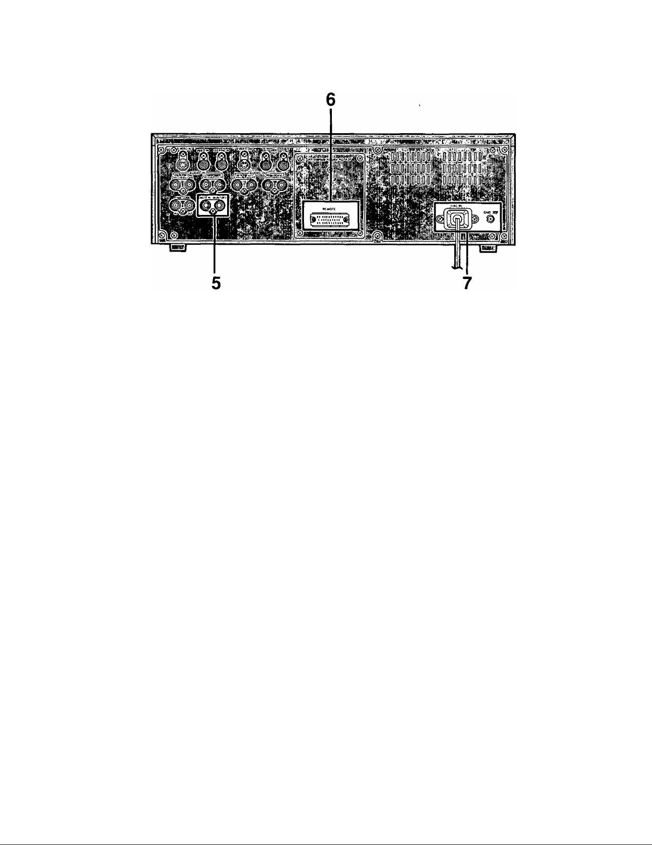
Rear Panel Parts
Video input signal area
S-VIDEO IN connector (AG-7350 only)
VIDEO IN connector (AG-7350 only)
EXT SYNC IN connector
..................................
..............
..................
S-VIDEO signal input connector.
Video signal input connector.
To synchronize with the external reference synchronizing signal.
Video output signal area
S-VIDEO OUT connector...................................S-VIDEO signal output connector.
VIDEO OUT (1,2) connectors
...................
... Video signal output connectors.
Audio signal area
NORM/Hi-Fi audio input connectors
(AG-7350 only)
Hi-Fi audio input connectors
(AG-7350 only)
NORM/Hi-Fi audio output connectors
Hi-Fi audio output connectors........................Output connectors for Hi-Fi sound only.
..........................
............
NORM/Hi-Fi audio (CH1/2) input connectors.
input connectors for Hi-Fi sound only.
.........
NORM/Hi-Fi audio (CHI/2) output connectors.
Time code signal area
TIME CODE IN connector (ag-7350 only)
TIME CODE OUT connector
.................
.. Time Code signal input connector.
.. Time Code signal output connector.
0)
CO
«
o
k_
'
c
o
o
o
o
5 Sensor remote recording/Monitor output area
SENSOR REMOTE connector (AG-7350 only).. Sensor remote signal recording connector.
AUDIO MONITOR OUT connector
................
Audio monitor signal output connector.
(D
Remote signal area
REMOTE connector
..................
Connector for remote search controller (AG-A600).
Power supply circuit area
AC IN socket.......................................................Connected to AC 120-240V power outlet.
GND terminal .....................................................When connecting this unit to any other component, make
absolutely sure that it is properly grounded by connecting this
terminal.
10
Setting the Switches
2 4
(The above illustration is AG-7350.)
CH2 METER Selector (AG-7350 only)
Used to adjust the audio (CH2) input level during recording. Set
this selector to "AUDIO CH2" before making adjustment for the
recording level of audio channel 2.
AUDIO MONITOR Selector
Used to select the audio channel which is to be heard on the
TV monitor or headphones through the HEADPHONE Jack on
the front panel or the AUDIO MONITOR OUT connector on the
rear panel of the unit.
cm: To monitor the audio signal from channel 1.
MIX:
CH2:
To monitor the mixed audio signals from channels
^ and 2 through the AUDIO MONITOR OUT
connector or HEADPHONES Jack. When using
headphones, audio channels 1 (left) and 2 (right)
can be monitored separately.
To monitor the audio signal channel 2.
METER Selector (No LEVEL meter for AG-7150.)
Used to display the recording level of Hi-Fi audio or normal
audio on the LEVEL meter and select the audio output signal
from the HEADPHONES Jack on the front panel or the AUDIO
MONITOR OUT connector on the rear panel.
Hi-Fi: Selects Hi-Fi audio.
NORM: Selects normal audio.
TRACKING
AUDIO
CH2
M
CH2 METER
Hi-Fi
NORM
AUDIO MONITOR
1
AUDIO MONITOR
I
■
t/i
O)
o
CO
S
</>
AUDIO OUT Selector
Used to select the audio output signal from the NORM/Hi-Fi
audio output connectors on the rear panel.
Hi-Fi: Discriminates between Hi-Fi and normal audio
automatically. When there is no Hi-Fi audio output
signal, normal audio will be automatically outputted.
NORM: Normal audio is outputted.
11
Setting the Switches
(cont.)
5. SENSOR REC Selector (AG-7350 only)
Used to select the mode to be recorded automatically.
REMOTE: To perform automatic recording of control signal
from the connector at rear panel.
OFF: Normally, set this switch to this position.
VIDEO: To detect the video input signal from the VIDEO IN
connector and record automatically.
VIDEO I
SENSOR REC
6. EXT TIMER Selector
Used to perform timer recording or playback.
PLAY: To perform timer playback with an external timer.
OFF: Normally, set this switch to this position.
REC: To perform timer recording with an external timer.
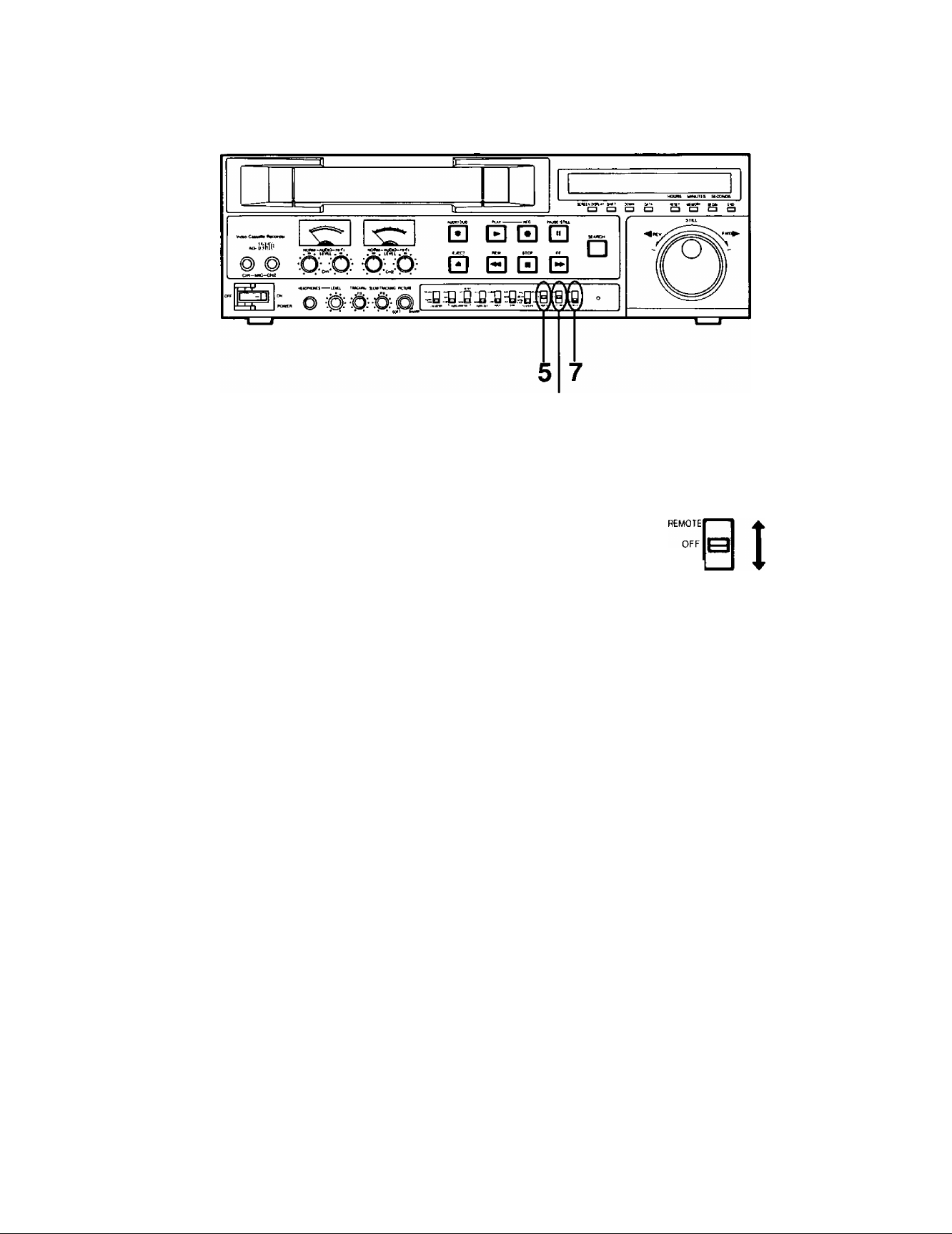
7. MODE LOCK Selector
ON: To operate the unit with a remote controller. When
this switch is set to this position, the operation
buttons on the front panel of the unit will be
rendered inoperative.
OFF: When this switch is set to this position, the
operation buttons on the front panel are operative
and the unit can also be controlled with the remote
controller.
AG-7350
at ;yi
EXT TIMER
ON
OFF
yi
MODE LOCK
AG-7150
EXT TIMER
12
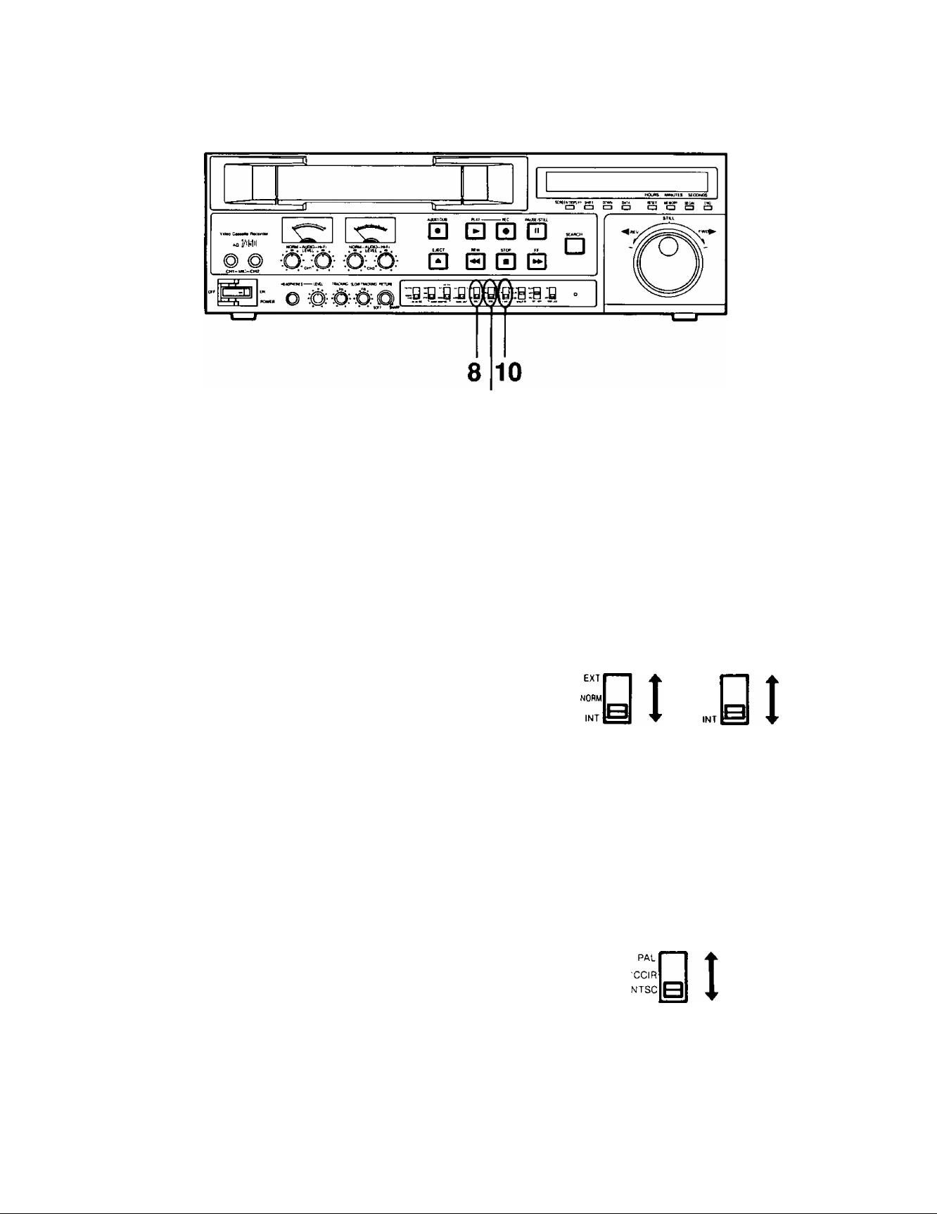
8. INPUT Signal Selector (AG-7350 only)
Used to select video input signal to be recorded.
S-VIDEO: To record video signal through the S-VIDEO IN
Connector.
LINE: To record video signal through the VIDEO IN
Connector.
S-VIDECI"^ ▲
uneIbI i
INPUT
SYNC Selector
Select the synchronizing signal.
EXT: To synchronize to the external composite sync
signal transmitted through the EXIT SYNC IN
Connector during playback or recording.
NORM: To synchronize to the video input signal transmitted
from the VIDEO IN Connector. (If there is no video
input signal, the “INT” mode will be selected.)
INT: To synchronize to the internal oscillator built in this
unit. (During recording, it will be automatically
synchronized to the video input signal.)
When setting to “EXT", be sure to input an external com
posite sync signal.
10. TV SYSTEM Selector
Used to select the 3 VMS system.
PAL:
CCIR:
NTSC
4.43:
To playback or record by PAL system.
To playback or record by CCIR system. (S-VHS
recording can not be made.)
To playback tapes recorded by NTSC system.
(Recording cannot be performed.)
AG-7350 AG-7150
EXT
SYNC
4,43
TV SYSTEM
SYNC
3
CO
PAL and CCIR systems can not be distinguished automat
ically.
If REC and PLAY Buttons are pressed simultaneously when
this selector is set to “NTSC 4.43”, the unit will automatically
go into playback mode.
13
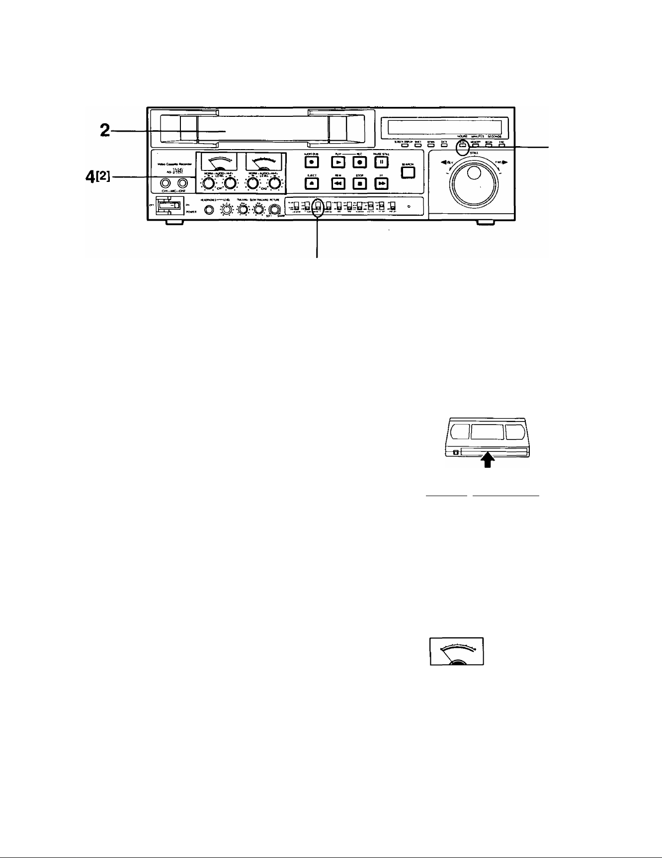
Recording (AG-7350 only)
Model AG-7150 is not equipped with recording function.
4[1]
1. Set the selectors.
INPUT Selector -+ "LINE" or “S-VIDEO” (Reler to page 13.)
SENSOR REC Selector —♦ "OFF" {Refer to page 12.)
EXT TIMER Selector -» "OFF" {Refer to page 12.)
S-VHS (ON-SCREEN) “ON" (Refer to pages 38 to 40.)
W
0)
U)
o'
O
•D
<D
0)
o
tA
—X
3
Insert the video cassette.
■ Make sure that the erasure prevention tab on the video cas
sette is intact.
Press the RESET Button.
■ The tape counter will be cleared.
4. Adjust the audio recording ievei.
[1] Select Hi-Fi audio or normal audio to be adjusted with the
METER Selector.
HI-FI: Hi-Fi audio recording level is displayed on the
LEVEL meter.
NORM; Normal audio recording level is displayed.
[2] Level adjustment
Adjust the recording level of Hi-Fi audio or normal audio by
rotating the audio level controls (CHI and CH2) until the LEVEL
meter point their maximum positions below “0”.
■ Be sure to set the "AUDIO LIMITER" mode in the initial set
ting menu on the TV monitor (ON-SCREEN) to "OFF" before
adjusting the normal audio recording level.
RESET MEMORY BEGIN END
1^ CD CD □
Hi-Fi
NORM
yi
AUDIO MONITOR
* CHI V
; CH2 ;
14
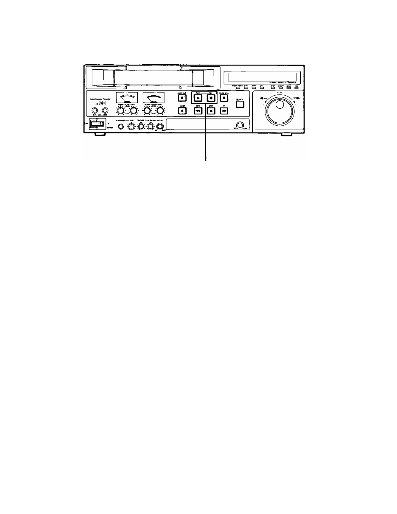
5. Press the REC and PLAY Buttons together.
■ Recording will start.
Notes
The AUDIO LIMITER function and the DOLBY NR system’s initial settings can be selected in the ON-SCREEN
mode.
• When the AUDIO LIMITER function is set “ON", the automatic volume control circuit in the unit permits audio
recording with less distortion at peak levels.
• The DOLBY NR system permits audio recording and playback with less noise.
Set the “HI-FI REC" mode in the initial setting menu on the TV monitor (ON-SCREEN) to “ON” to perform Hi-Fi
audio recording.
If Hi-Fi audio recording is not intended, be sure to not only set the LEVEL meter to "0”, but also the “Hl-F! REC”
mode of the ON-SCREEN to “OFF”.
PLAY'
■REC
o
'«
m
«
c
o
(0
0)
Q.
u
to
15
Playback
4[2][3] 4[1]
1. Set the selectors.
SENSOR REC Selector
EXT TIMER Selector
► "OFF" (AG'7350 only) (Refer to page 12.)
*■ "OFF” (Refer to page 12.)
*o
CD
0)
w_
o'
O
Í0
0)
5‘
3
(A
Insert the video cassette.
■ Insert the tape with the recorded sound and pictures which
are to be played back.
Press the PLAY Button.
■ Playback will start.
4. Adjust the Tracking.
[1 ] Set the CH2 METER Selector to "TRACKING”.
{AG-7350 only)
[2] In case of AG-7350:
Slowly rotate the TRACKING Control clockwise or counter
clockwise so that the meter deflection is maximized.
Incase of AG-7150:
Slowly rotate the TRACKING Control clockwise or counter
clockwise to reduce the noise for a normal image.
[3] Return the TRACKING Control to its center “FIX" position
after playback is finished.
■ TRACKING should be readjusted when playing back tapes
recorded on another VTR.
TRACKING
AUDIO
CH2
TRACKING
PLAY
Í
CH2 METER
.FIX.
• •
• •
16
 Loading...