

Panasonic AFP0HC32ET, AFP0HC32EP User Manual

Programmable Controller
FP0H Control Unit
User's Manual
EtherNet/IP Edition
[Applicable model]
AFP0HC32ET/AFP0HC32EP
WUME-FP0HEIP-05
2021.2 panasonic.net/id/pidsx/global

(MEMO)
2 WUME-FP0HEIP-05

Introduction
Thank you for purchasing a Panasonic product. Before you use the product, please carefully
read through the user’s manual, and understand it in detail to use the product properly.
Types of Manual
● This manual describes the "EtherNet/IP communication function" implemented in FP0H
Control Unit.
● There are different types of user’s manual for the FP0H series. Please refer to a relevant
manual for the unit and purpose of your use.
● The manuals can be downloaded on our download center: https://
industrial.panasonic.com/ac/e/dl_center/.
Unit name or purpose of
use
FP0H Control Unit
Positioning Function/PWM
Output/High-speed
Counter Function
Serial Communication
Function
Ethernet Communication
Function
EtherNet/IP
Communication Function
Logging trace function FP0H User‘s Manual (Logging/Trace Function) WUME-FP0HLOG
FP0H Extension
(Communication) Cassette
FP0H Positioning Unit FPsigma Positioning Unit User’s Manual ARCT1F365E
FP0H Positioning Unit RTEX
Manual name Manual code
FP0H User‘s Manual (Basic) WUME-FP0HBAS
FP0H Programming Manual WUME-FP0HPGR
FP0H Programming Manual (SD Card Access
Instructions)
FP0H User‘s Manual
(Positioning/PWM Output/High-speed Counter)
FP0H User‘s Manual (COM Communication) WUME-FP0HCOM
FP0H User‘s Manual (Ethernet Communication) WUME-FP0HET
FP0H User‘s Manual (EtherNet/IP) WUME-FP0HEIP
FP0H User‘s Manual (COM Communication) WUME-FP0HCOM
FP0H Positioning Unit RTEX User’s Manual
(FPWIN GR7)
WUME-FP0HSD
WUME-FP0HPOS
WUME-FP0HRTEXGR7
WUME-FP0HEIP-05 iii
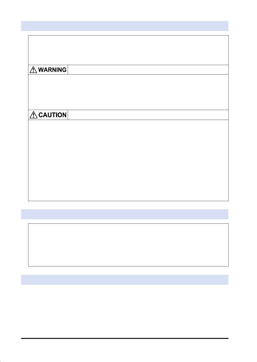
SAFETY PRECAUTIONS
● To prevent accidents or personal injuries, please be sure to comply with the following items.
● Prior to installation, operation, maintenance and check, please read this manual carefully for proper use.
● Before using, please fully understand the knowledge related to the equipment, safety precautions and all
other precautions.
● Safety precautions are divided into two levels in this manual: Warning and Caution.
Incorrect operation may lead to death or serious injury.
● Take appropriate safety measures to the external circuit of the product to ensure the security of the whole
system in case of abnormalities caused by product failure or external.
● Do not use this product in areas with inflammable gases.
Otherwise it may lead to an explosion.
● Do not put this product into a fire.
Otherwise it could cause damage to the battery or other electronic parts.
Incorrect operation may lead to injury or material loss.
● To prevent the excessive exothermic heat or smoke generation of the product, a certain margin is required
for guaranteed characteristics and performance ratings of relative products.
● Do not decompose or transform it.
Otherwise it will lead to the excessive exothermic heat or smoke generation of the product.
● Do not touch terminal blocks during power-on.
Otherwise it may result in an electric shock.
● Set an emergency stop and interlock circuit in the external devices.
● Connect wires and connectors reliably.
Otherwise it may lead to the excessive exothermic heat or smoke generation of the product.
● Do not undertake construction (such as connection and disconnection) while the power supply is on.
It could lead to an electric shock.
● If the equipment is used in a manner not specified by the Panasonic, the protection provided by the
equipment may be impaired.
● This product has been developed/produced for industrial use only.
Description on Copyright and Trademarks
● The copyright of this manual is owned by Panasonic Industrial Devices SUNX Co., Ltd
● Unauthorized reproduction of this manual is strictly prohibited.
● Windows is a registered trademark of Microsoft Corporation in the U.S. and other countries.
● Ethernet is a registered trademark of Fuji Xerox Co., Ltd. and Xerox Corporation.
● EtherNet/IP is a registered trademark of ODVA (Open DeviceNet Vendor Association).
● SDHC and SD logos are trademarks of LLC.
● Other company and product names are trademarks or registered trademarks of their respective companies.
Network Security
When this product is connected to a network, you might receive damage as listed below.
(1) Information leakage or outflow through this product
(2) Fraudulent operation of this product by a malicious third party
(3) Obstructing or stopping this product by a malicious third party
Sufficient network security measures, including the following measures, should be taken at your
own risk to prevent such damages.
● Use this product on a network where safety is secured by using a firewall.
iv
WUME-FP0HEIP-05

● When using this product on a system where a PC is connected, make sure that checking and
cleaning of infection by computer virus or malicious program is performed periodically.
● In order to prevent malicious attacks, set user name and password to limit users who can log
in.
● Take measures such as limiting an access through a user authentication method so as not to
leak information to the network such as image data, authentication information (user name
and password), alarm email information, FTP server information, DDNS server information,
etc.
● Be sure to close all browsers immediately after accessing this product as an administrator.
● Periodically change the administrator's password.
● Do not install this product in a location where the product or cables can be easily damaged.
● Furthermore, it is recommended that the product be used in an environment that has VPN
(Virtual Private Network) or leased line network.
Glossary
The following terms are used in this manual and the EtherNet/IP setting tool.
Term Description
Originator
Target he side which the connection is opened is called target, such as PLC, I/O devices.
Scan List
I/O map
EDS file
(Electric data sheet)
Node no.
Connection setting The details of the connections with targets registered in the scan list are set.
Node name Arbitrary node names can be given.
Device name Device names of targets. The device name is registered in the EDS file.
Connection Name
Application Type
The side which opens the connection of the cyclic communication is called
originator, i.e. controllers such as PLC.
Connection setting with targets registered in FP0H. Information required for the
communication with the targets and the device allocation of own unit are registered.
For FP0H, the connection with targets are established according to the scan list.
Information required for the transmission from the own unit (FP0H) to other PLCs
and the device allocation of the own unit are registered.
EDS files are provided for each product by each vendor. This file contains the
information on the communication for registering targets in the scan list.
The EDS files of each target should be registered for constructing the scan list with
the setting tool.
A node number is set when a target is registered in the scan list.
Numbers that do not overlap are allocated in the scan list as node numbers.
Node numbers are not used in the cyclic communication, however, as each target
is recognized by these numbers, they are used for monitoring the communication
state of each node or controlling the start/stop of the communication.
The type of the connection manager registered in the EDS file is selected by the
name. By selecting this, the application type (communication method) is changed.
The communication method can be selected by the application type.
Three communication methods are available;
1: Exclusive Owner (Two-way communication)
2: Input Only
3: Listen Only
Although "Exclusive Owner" and "Input Only" are independent connections, "Listen
Only" can be connected only when either of the above connections is established,
and it will be automatically cut if the independent connection is disconnected.
Also, it will be reconnected automatically when the above independent connection
is reconnected.
When FP0H is used as a target, "Input Only" can be selected.
WUME-FP0HEIP-05 v

Term Description
Set the operation method of "Compatibility Check" , which checks the information of
the connected target device against the revision of the EDS file.
Three verification methods are available. The default is "Follow Adapter(Target)
Compatibility Check
Communication Method
(Tag/Instance)
Input Send Trigger
COS Transmission
Disable Time
Timeout Period
Input Information (T>O) This is the setting for the transmission from a target to the FP0H (originator).
Output Information (O>T) This is the setting for the transmission from the FP0H (originator) to a target.
RPI
(Requested Packet
Interval)
Point to Point
(1:1 communication)
Multicast
(Multicast communication)
TTL
Instance ID/Tag name
Data Size
Rule".
1: Check
2: Not check
3: Follow Adapter(Target) Rule
For connecting from an originator to target, there are two methods to specify the
device area of the target.
by specifying numbers (Instance)
by specifying symbols (Tag).
When setting connections, the methods available for each target are displayed.
For using the FP0H as a target, either method can be selected.
However, the selectable instance numbers for the instance method are 100 to 199.
The transmission timing is selected from Cyclic or COS (Change of state).
However, COS depends on devices.
COS is basically a cyclic communication, however, it also performs transmission
when sent data changes.
The FP0H does not support COS.
Transmission disable time (RPI of input information x 1/4) is displayed when "Input
Send Trigger" is set to "Change of State (COS)".
Even if the unit detects the change in data, it is not sent within the transmission
disable time.
In the cyclic communication, transmission data is sent as UDP packet. The timeout
is judged on a receiver side.
The timeout period is selected from 4, 8, 16, 32, 64, 128, 256 and 512 times of RPI.
The timeout period should be 10 msec or more.
RPI can be specified for T>O direction and O>T direction separately, so each
timeout period may be different values.
Set the transmission interval for the cyclic communication. Set a value within the
communication capacity of a target. The usable RPI range depends on devices.
For the FP0H, it is 1 ms to 10 s (by 0.5 ms).
One to one communication is performed between an originator and a target.
Transmitted packets are received only by each other.
Other devices connected to the same HUB do not receive those transmission
packets.
Transmission data is sent as a multicast packet. By connecting multiple originators
to one target, one multicast packet can be received by multiple originators.
(Note) Multicast packets are basically received by all devices connected to the
same HUB which includes the devices unrelated to the communication, and it leads
to an unnecessary communication load.
When using the multicast communication, set not to exceed 100% by the load
factor calculation of the setting tool.
TTL (Time To Live) is used to set the hierarchies of the network in which
transmission packets can exist when sending multicast packets to other PLCs.
Set an instance ID or tag name according to the communication method of the
selected connection.
The data sizes of the originator and target for the cyclic communication must be the
same. When they do not match, the communication cannot be performed.
vi WUME-FP0HEIP-05

Term Description
Parameter setting
PPS performance index
(Packet per sec)
Normal packet and
large packet
Protocol used for
cyclic communication
Heartbeat
Forward open
Large forward
open
RUN/IDLE bit
Data size, instance ID and other parameters that can be changed in the EDS file
can be changed.
This is an index of sent/received packets processed in one second.
The packet whose size is within 510 bytes is called normal packet. The packet
whose size is 511 bytes to 1444 bytes is called large packet.
The maximum communication performance varies according to the data size used
for communication.
Performance index of FP0H
For 510 bytes or less: Max. 5000 pps
For 511 bytes or more: Max. 2500 pps
The cyclic communication is performed using UDP. The used port number is 2222.
For "Input Only" or "Listen Only", a packet called heartbeat whose data size is zero
is sent from the originator (FP0H). For the RPI of the heartbeat, the value 16 times
of the RPI of transmitted data from a target is automatically applied.
The heartbeat is used for confirming the continuation of the connection on the
target side. It is used for detect the timeout.
This is a command for opening the connection of EtherNet/IP and sent using TCP.
The used port number is 44818.
This is a command for opening the connection when sending/receiving data whose
size is larger than 511 bytes.
Operation state flag (RUN/IDLE) sent by connected devices in cyclic
communication.
RUN : 1
IDLE : 0
When the RUN/IDLE bit of the originator does not change to RUN, the target may
not operate properly. For details, refer to "5.2.3 RUN/IDLE Bit".
● Do not use "2222" and "44818" for the port numbers set to the connections of Ethernet
communication.
WUME-FP0HEIP-05
vii

(MEMO)
viii WUME-FP0HEIP-05

Table of Contents
1 FP0H EtherNet/IP Function ..................................................................1-1
1.1 What is EtherNet/IP? ..........................................................................1-2
1.1.1 Overview of EtherNet/IP .................................................................. 1-2
1.1.2 FP0H EtherNet/IP Function ............................................................. 1-2
1.2 Names and Functions of Parts............................................................1-4
1.2.1 Control Unit ...................................................................................... 1-4
1.2.2 LED Displays When PLC Operates ................................................. 1-4
1.3 Restrictions .........................................................................................1-6
2 Cyclic Communication .........................................................................2-1
2.1 Cyclic Communication Function..........................................................2-2
2.1.1 Overview of Cyclic Communication ................................................. 2-2
2.1.2 Operation of Cyclic Communication................................................. 2-3
2.1.3 Data Refresh of Cyclic Communication ........................................... 2-3
2.1.4 Data Area Specifications Using Tag/Instance .................................. 2-4
2.2 Cyclic Communication of FP0H ..........................................................2-6
2.2.1 Connection using FP0H as originator .............................................. 2-6
2.2.2 Connection Using FP0H as Target................................................... 2-7
2.2.3 Example of Configuration When FP0H is Originator and Target...... 2-7
3 Setting Procedure .................................................................................3-1
3.1 Overview of Settings...........................................................................3-2
3.1.1 System Example .............................................................................. 3-2
3.1.2 Setting Procedure ............................................................................ 3-2
3.2 Initial Setting of Ethernet /IP ...............................................................3-4
3.2.1 Ethernet Settings ............................................................................. 3-4
3.2.2 Starting EtherNet/IP Setting Screen ................................................ 3-5
3.2.3 EtherNet/IP Basic Configuration ...................................................... 3-5
3.2.4 Items of Ethernet /IP Basic Configuration ........................................ 3-6
3.3 Settings of Connection Using FP0H as Originator..............................3-8
3.3.1 Settings ............................................................................................ 3-8
3.3.2 Registering EDS File of Target Device............................................. 3-8
3.3.3 Adding Target in Scan List ............................................................... 3-9
3.3.4 Setting IP Address of Target ............................................................ 3-10
3.3.5 Setting Tag/Instance ........................................................................ 3-11
3.3.6 Specifying Data Area Corresponding to Tag/Instance ..................... 3-13
3.3.7 Reference: Setting of Target "FP0H(B)"........................................... 3-15
3.4 Settings of Connection Using FP0H as Target ...................................3-16
3.4.1 Settings ............................................................................................ 3-16
3.4.2 Adding I/O Map to Scan List ............................................................ 3-16
3.4.3 Registering Tag Name/Instance ID .................................................. 3-17
3.4.4 Registering Data Area Corresponding to Tag/Instance.................... 3-18
3.4.5 Reference: Setting of Originator "FP7" ............................................ 3-19
3.5 Confirmation of Load Factor Calculation.............................................3-21
3.5.1 Load Factor Calculation ................................................................... 3-21
WUME-FP0HEIP-05
ix

3.5.2 Displaying Load Factor Calculation ................................................. 3-21
3.6 Saving EtherNet/IP Settings ...............................................................3-22
3.6.1 Saving EtherNet/IP Settings in Project ............................................ 3-22
3.6.2 Saving/Reading EtherNet/IP Settings in File ................................... 3-22
3.6.3 Writing EtherNet/IP Settings to FP0H .............................................. 3-23
4 Tool Operation.......................................................................................4-1
4.1 Scan List Window ...............................................................................4-2
4.1.1 Display Contents of Scan List Window ............................................ 4-2
4.1.2 Operations in Scan List Window ...................................................... 4-3
4.2 Device List Window.............................................................................4-7
4.2.1 Display Contents of Device List Window ......................................... 4-7
4.2.2 Operations from EDS File Menu...................................................... 4-7
4.3 Various Setting Screens......................................................................4-9
4.3.1 Operations in Device Setting Screen ............................................... 4-9
4.3.2 Operations in Connection Setting Screen........................................ 4-9
4.3.3 Operations in I/O Map Setting Screen ............................................. 4-12
4.3.4 Display Contents of Calculate Load Factor Screen ......................... 4-13
4.3.5 Display Contents of Device Property Screen................................... 4-15
4.3.6 Switching Tabs in Each Setting Screen ........................................... 4-16
5 Startup and Operation ..........................................................................5-1
5.1 Startup Operation of Cyclic Communication.......................................5-2
5.1.1 When FP0H is Originator ................................................................. 5-2
5.1.2 When FP0H is Target....................................................................... 5-3
5.2 Checking EtherNet/IP Communication State......................................5-4
5.2.1 Unit Annunciation Relays................................................................. 5-4
5.2.2 Cyclic Communication State Tables of EtherNet/IP ......................... 5-4
5.2.3 RUN/IDLE Bit ................................................................................... 5-4
5.3 Judgement and Operation of Abnormality ..........................................5-6
5.4 Delay Time of Communication Data ...................................................5-7
5.4.1 Delay time of sent data .................................................................... 5-7
5.4.2 Delay Time of Reception Data ......................................................... 5-7
6 Instruction References .........................................................................6-1
6.1 High-level Instructions Used for EtherNet/IP Control..........................6-2
6.1.1 Information Acquisition of EtherNet/IP (F465 ETSTAT) ................... 6-2
7 Reference Information..........................................................................7-1
7.1 Calculation Method of Load Factor.....................................................7-2
7.2 Cyclic Communication: List of Abnormal Statuses .............................7-5
7.3 PLC Link and Ethernet Switch ............................................................7-8
8 Appendix................................................................................................8-1
8.1 Supported Data Types........................................................................8-2
x
WUME-FP0HEIP-05

1 FP0H EtherNet/IP Function
1.1 What is EtherNet/IP? ..........................................................................1-2
1.1.1 Overview of EtherNet/IP .................................................................. 1-2
1.1.2 FP0H EtherNet/IP Function ............................................................. 1-2
1.2 Names and Functions of Parts............................................................1-4
1.2.1 Control Unit ...................................................................................... 1-4
1.2.2 LED Displays When PLC Operates ................................................. 1-4
1.3 Restrictions .........................................................................................1-6
WUME-FP0HEIP-05 1-1
FP0H
Connection 1
Connection 2
: Opens connection. : Sends cyclic data.
PLC
Originator
Target Originator
Target
1.1 What is EtherNet/IP?
1.1 What is EtherNet/IP?
1.1.1 Overview of EtherNet/IP
EtherNet/IP (Ethernet Industrial Protocol) is an industrial multi-vendor realtime Ethernet system
for executing the communication protocol for CIP (Common Industrial Protocol) control in an
application layer on standard Ethernet.
Cyclic communication can be performed among devices compatible with EtherNet/IP. In cyclic
communication, devices compatible with EtherNet/IP send or receive data between "specified
data areas" in a "specified cycle". Even when the number of nodes increases, the cycle does
not increase.
For information on CIP, refer to the documents of ODVA.
1.1.2 FP0H EtherNet/IP Function
The FP0H can perform the cyclic communication with PLCs and I/O devices compatible with
EtherNet/IP on the EtherNet/IP network.
The send and receive areas are allocated from the device area of the FP0H for the cyclic
communication. Data is sent/received from the allocated area with specified intervals (RPI).
The EtherNet/IP function of FP0H is set from the "EtherNet/IP settings" menu of programming
software FPWIN GR7.
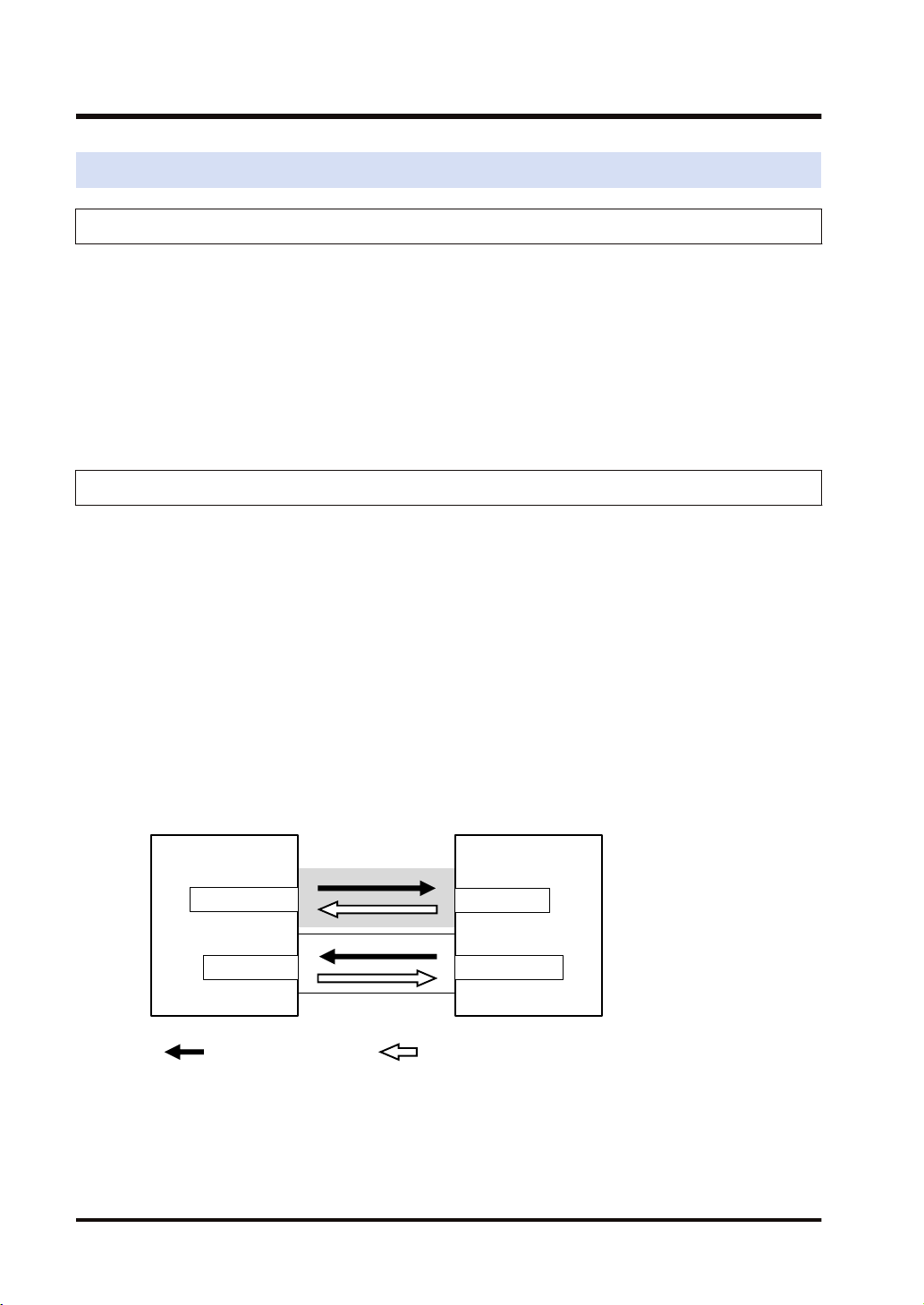
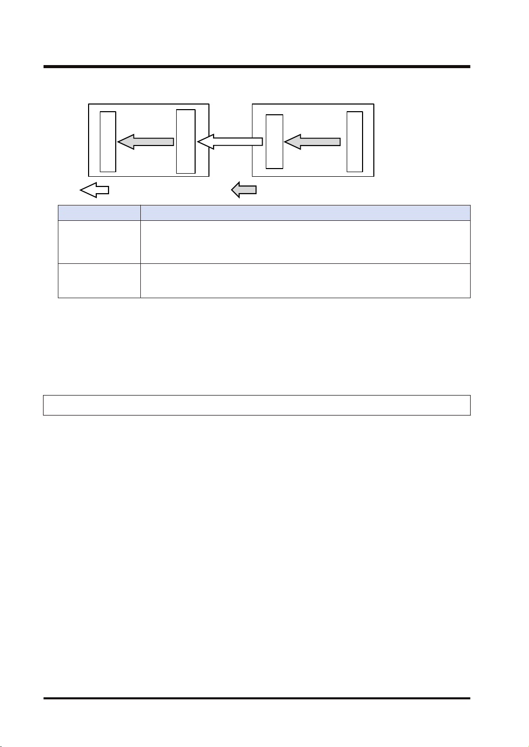
■
Originator and Target
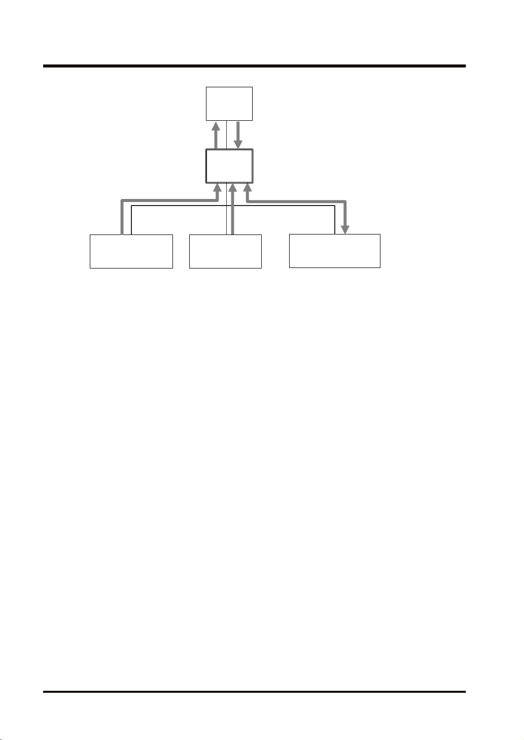
In each connection (communication line) of cyclic communication, there are "originator" which
opens each connection and "target" which a connection is opened.
The PLC (FP0H) can be set as the both originator and target.
For the communication between the FP0H and a PLC, the settable connection is "Input Only"
(i.e. data can be sent in one direction, from target to originator). By using two connections, data
can be sent and received.
For the communication between the FP0H and other I/O devices, the FP0H is the originator.
According to devices, the data transmissions by "Input Only" (from target to originator) and
"Exclusive Owner" (two-way) may be available.
1-2 WUME-FP0HEIP-05
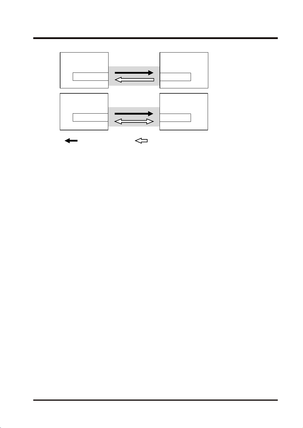
FP0H
Connection
Input Only
: Opens connection. : Sends cyclic data.
I/O device
Originator
Target
FP0H
Connection
Exclusive Owner
I/O device
Originator
Target
1.1 What is EtherNet/IP?
WUME-FP0HEIP-05 1-3
1.2 Names and Functions of Parts
1.2 Names and Functions of Parts
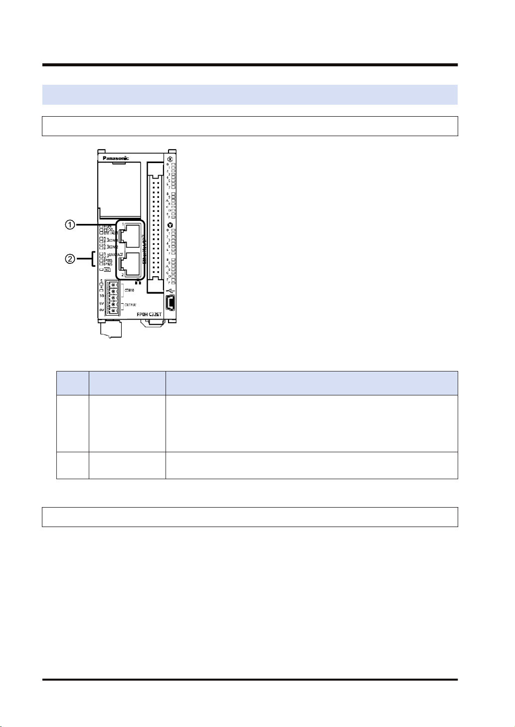
1.2.1 Control Unit
■
Names and Functions of Parts
Numb
er
Name Description
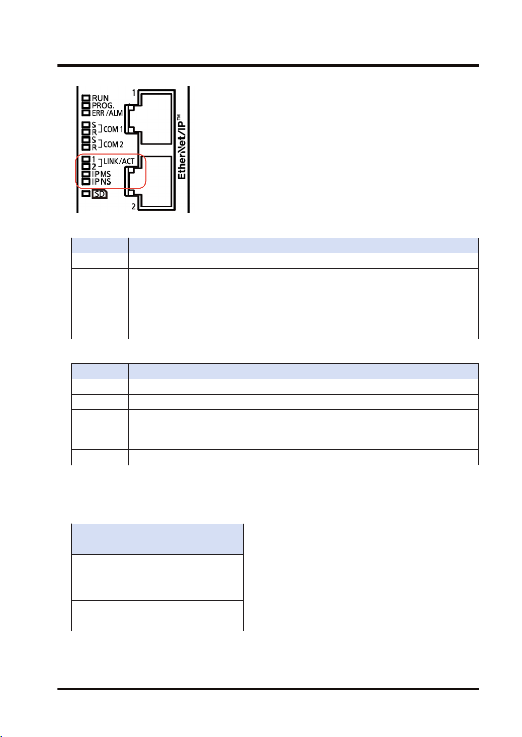
(1) LAN port
Operation monitor
(2)
LED
It is mounted to the FP0H Control Unit (Ethernet type). It is used for connecting
to Ethernet and EtherNet/IP.
The IP address and MAC address are common to the LAN ports 1 and 2. The
wiring can be simplified by using the two ports.
The MAC address is printed on the side face of the unit.
IP MS: Displays the operating condition of the unit.
IP NS: Displays the communication status of network.
1.2.2 LED Displays When PLC Operates
The state of the PLC can be confirmed from the lighting state of the LEDs when the PLC is
operating. The PLC states indicated by the LEDs are as follows.
1-4 WUME-FP0HEIP-05
1.2 Names and Functions of Parts
MS (Module status indicator) <Green/Red>
LED display PLC state
LED OFF The EtherNet/IP function is disabled.
Green ON The EtherNet/IP function is normally activated.
Green
Flashing
Red ON Unrecoverable fault occurs.
Red Flashing Recoverable fault occurs. (such as a setting that load factor exceeds)
This state does not exist.
NS (Network status indicator) <Green/Red>
LED display PLC state
LED OFF The EtherNet/IP function is disabled or IP address is not established.
Green ON More than one connection is established.
Green
Flashing
Red ON IP address duplication is detected.
Red Flashing This state does not exist.
■
LED displays when PLC is started
Connection is not established, but IP address is acquired.
The MS and NS LEDs turn on in the following order when the FP0H is started.
Each lighting time of the lighting order 1 to 4 is 0.25 seconds.
Lighting
order
1 Green ON OFF
2 Red ON OFF
3 Green ON Green ON
4 Green ON Red ON
5 Green ON OFF
Lighting state
MS NS
WUME-FP0HEIP-05 1-5
1.3 Restrictions
1.3 Restrictions
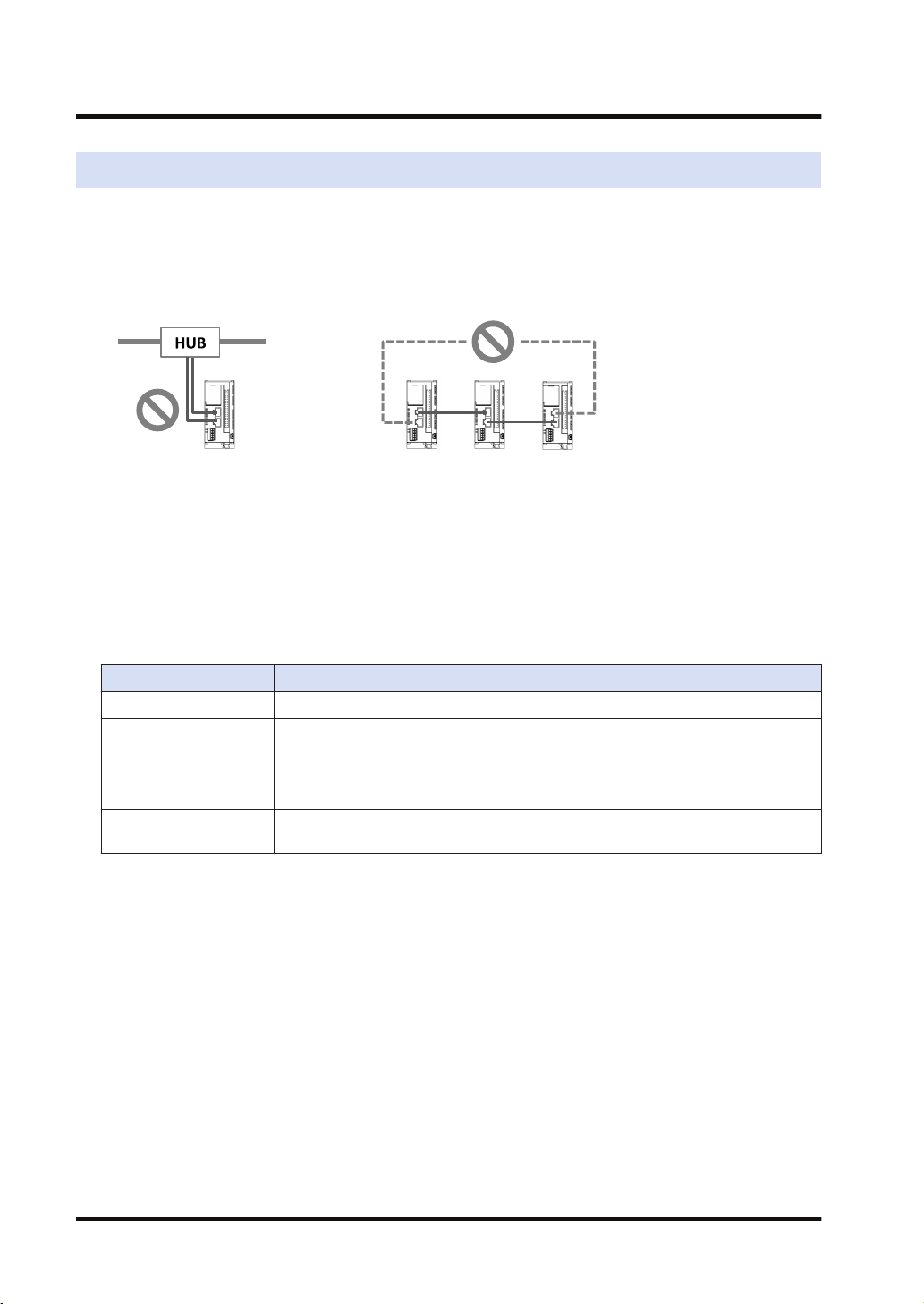
■
Connecting to External Devices
LAN ports 1 and 2 have the same IP address and MAC address.
● Do not connect the cables from the two LAN ports to the same switching HUB.
● When performing daisy chain connection, do not connect devices in a ring shape.
■
Number of connections
For the FP0H, the total number of connections of Ethernet communication and EtherNet/IP
communication should be 9 or less. For the details of the setting of the number of connection,
refer to "3.2.1 Ethernet Settings".
(The no. of user connections of Ethernet communication) + (EtherNet/IP communication) 9
connections
■
Restrictions by FP0H specifications
Item Specifications
RPI 1 to 10000 ms (In 0.5 ms unit)
Cyclic communication
allowable
communication band
Usable devices WX, WY, WR, WL, DT, LD
Device specification of
each tag/instance
5000 pps (Packet size: 2 to 510 bytes)
2500 pps (Packet size: 511 to 1450 bytes)
Max. 8 devices
1-6 WUME-FP0HEIP-05

2 Cyclic Communication
2.1 Cyclic Communication Function..........................................................2-2
2.1.1 Overview of Cyclic Communication ................................................. 2-2
2.1.2 Operation of Cyclic Communication................................................. 2-3
2.1.3 Data Refresh of Cyclic Communication ........................................... 2-3
2.1.4 Data Area Specifications Using Tag/Instance .................................. 2-4
2.2 Cyclic Communication of FP0H ..........................................................2-6
2.2.1 Connection using FP0H as originator .............................................. 2-6
2.2.2 Connection Using FP0H as Target................................................... 2-7
2.2.3 Example of Configuration When FP0H is Originator and Target...... 2-7
WUME-FP0HEIP-05 2-1
Opens connections.
PLC PLC
I/O device
Originator
Target
Cyclic communication
PLC PLC
I/O device
Originator
Target
2.1 Cyclic Communication Function
2.1 Cyclic Communication Function
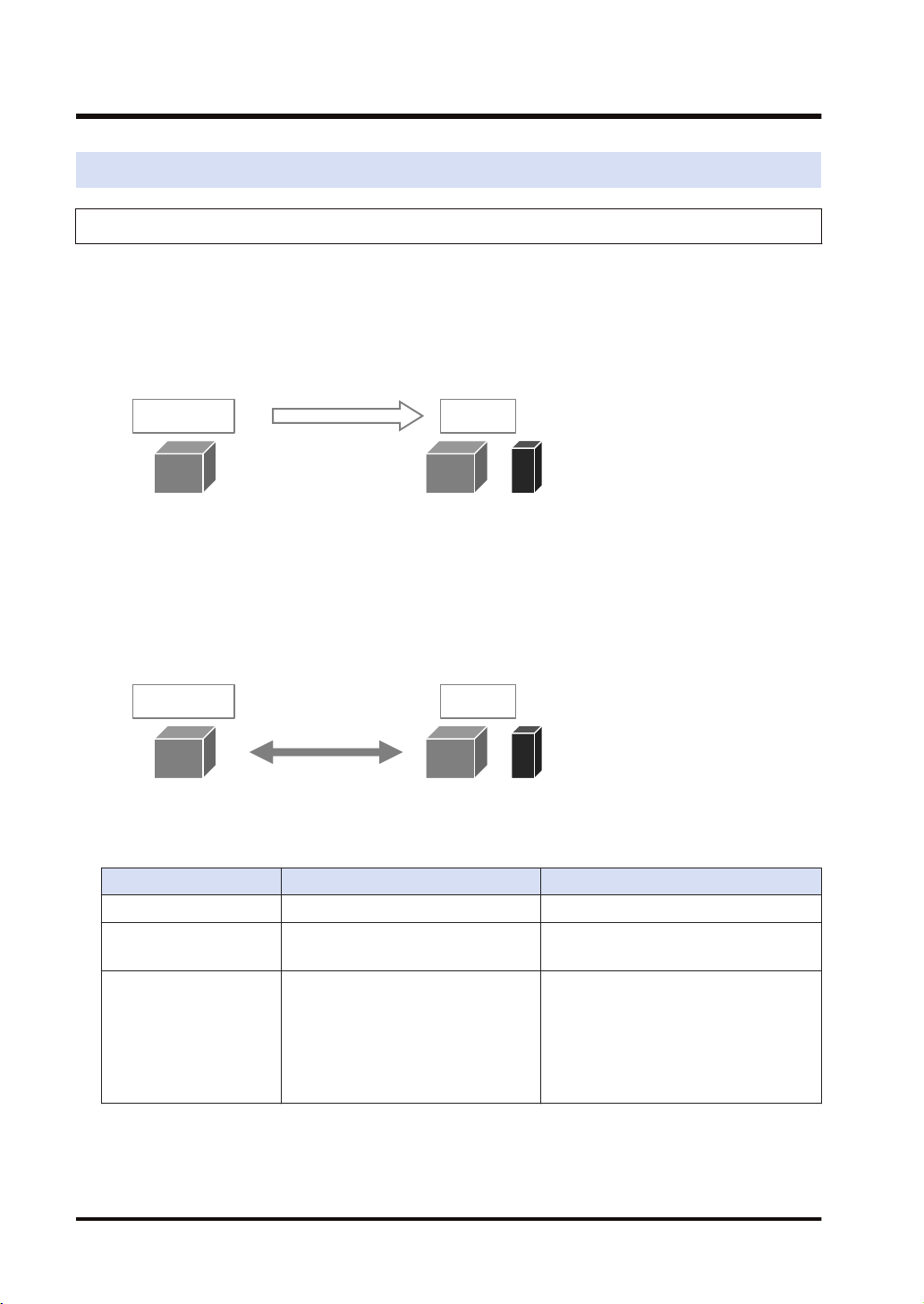
2.1.1 Overview of Cyclic Communication
The cyclic communication is a function to perform data transmission with constant intervals
(RPI) between PLC and PLC or PLC and I/O device on the EtherNet/IP network.
In the cyclic communication, one device opens a communication line which is called connection
for a destination device. The side which opens the connection (communication line) is called
"originator", and the side which the connection is opened is called "target".
Connection information on the cyclic communication is set in the originator. The originator
connects to the target according to the connection information. The tag/instance required for the
connection from the originator is registered in the target.
Once the connection is open, the cyclic communication begins according to the settings of the
connection information.
Comparison of originator and target
Item Originator Target
Applicable model PLC PLC, I/O device
When starting
communication
Connection information
2-2 WUME-FP0HEIP-05
Opens connections.
(Connects to targets.)
Target connection information
● IP Address
● Tag/Instance
Cyclic communication information
● RPI
● Communication method, etc.
Connection is opened.
(Connected from originator.)
Connected from originator
● Tag/Instance
Send buffer
Receive buffer
Data area
Receive buffer
Send buffer
Data area
Input Only
Exclusive Owner
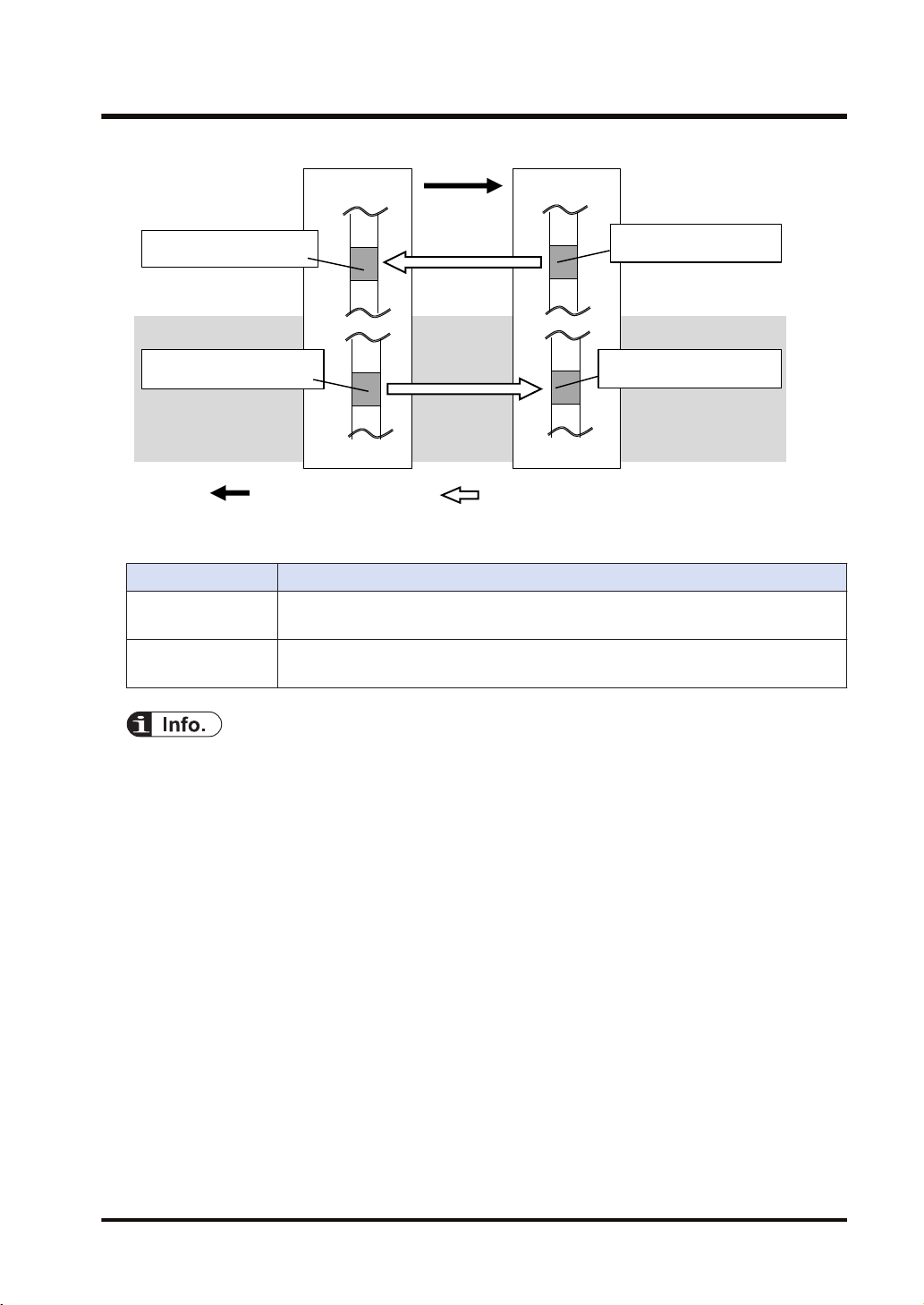
: Sends cyclic data. : Refreshes data.
Receive buffer
Send buffer
Data area
Data area
Originator
Target
2.1 Cyclic Communication Function
2.1.2 Operation of Cyclic Communication
The communication behavior in the cyclic communication varies according to the settings of
connections.
Description
Input Only Data is sent in the input direction only (From target to originator)
Exclusive Owner Data is sent bi-directionally.
(Note 1) The transfer operations Data area>Send buffer and Receive buffer>Data area in each device are
● For some target devices, "Exclusive Owner" setting is not available.
● When PLCs including FP0H are set as targets, "Input Only" setting is only available.
● For sending/receiving data between PLC and PLC, it is necessary to use two connections
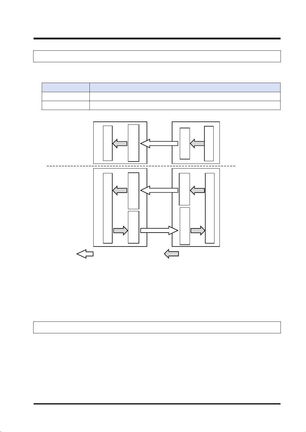
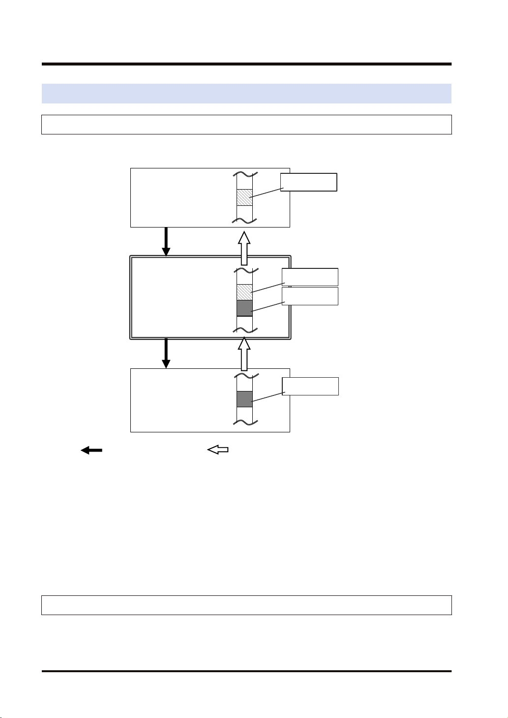
2.1.3 Data Refresh of Cyclic Communication
In the cyclic communication, data is refreshed in synchronization with operation cycle and RPI.
The refresh of sent data and received data is controlled for each RPI.
WUME-FP0HEIP-05 2-3
called "Refresh".
and open them each other.
Send buffer
Receive buffer
Data area
: Sends cyclic data. : Refreshes data.
Data area
Input
refresh
Output
refresh
<Receiver side>
<Sender side>
2.1 Cyclic Communication Function
Refresh direction Refresh operation
In refresh processing at the beginning of scan, if there is incoming data in the receive
Input refresh
Output refresh
■ Refresh operation when starting communication
● After confirming that the connection is open with the connection open flag, refreshes sent
data.
● After detecting received data with the received data existence flag, refreshes received data.
● After refreshing received data, the normal reception active flag turns ON.
buffer for the cyclic communication, it is copied to the operation memory. After the
completion of the refresh operation, the latest received data will be an object to be
refreshed in the next time.
In refresh processing at the beginning of scan, if there is space in the send buffer for the
cyclic communication, it is copied from the data area. If the refreshing has not been
completed at the time of data transmission, the previous refreshed data is sent.
2.1.4 Data Area Specifications Using Tag/Instance
In the cyclic communication, the data send and received areas are specified using "Tag" or
"Instance".
● For "Tag", the areas are specified by symbols. For "Instance", they are specified by numbers.
● For some target devices, only either of "Tag" and "Instance" may be available.
● In the connection of "Exclusive Owner", the receive area of each target is specified by
another tag or instance.
(Note) Even when specifying by tag, numbers are assigned to packets during the actual cyclic
communication.
2-4 WUME-FP0HEIP-05
Exclusive Owner only
TargetOriginator
: Opens connection. : Sends cyclic data.
Data area
Data area
Instance (100)
When specifying "Instance"
Tag (Tag_1)When
specifying "Tag"
Tag (Tag_1)
When specifying "Tag"
Instance (100)
When specifying "Instance"
Settings of target and originator
Settings
Originator
Target
Tag/Instance of connected target
Data area/size of originator corresponds to Tag/Instance
Tag/Instance connected from originator
Data area/size of target corresponds to Tag/Instance
2.1 Cyclic Communication Function
● In each connection, the sizes of the data areas which correspond to the originator and target
should be the same.
● For the FP0H, the data areas of each connection can be allocated to the operation memories in
a maximum of 8 areas. Device names that can be allocated are WX, WY, WR, WL, LD, and DT.
For the automatic allocation, the WL and LD areas are used.
WUME-FP0HEIP-05 2-5
Low-order PLC
Input Only
I/O device
Exclusive Owner
Target 1 Target 2
Connection 1
Receiving data
FP0H
Connection 2
Sending/Receiving data
Originator
2.2 Cyclic Communication of FP0H
2.2 Cyclic Communication of FP0H
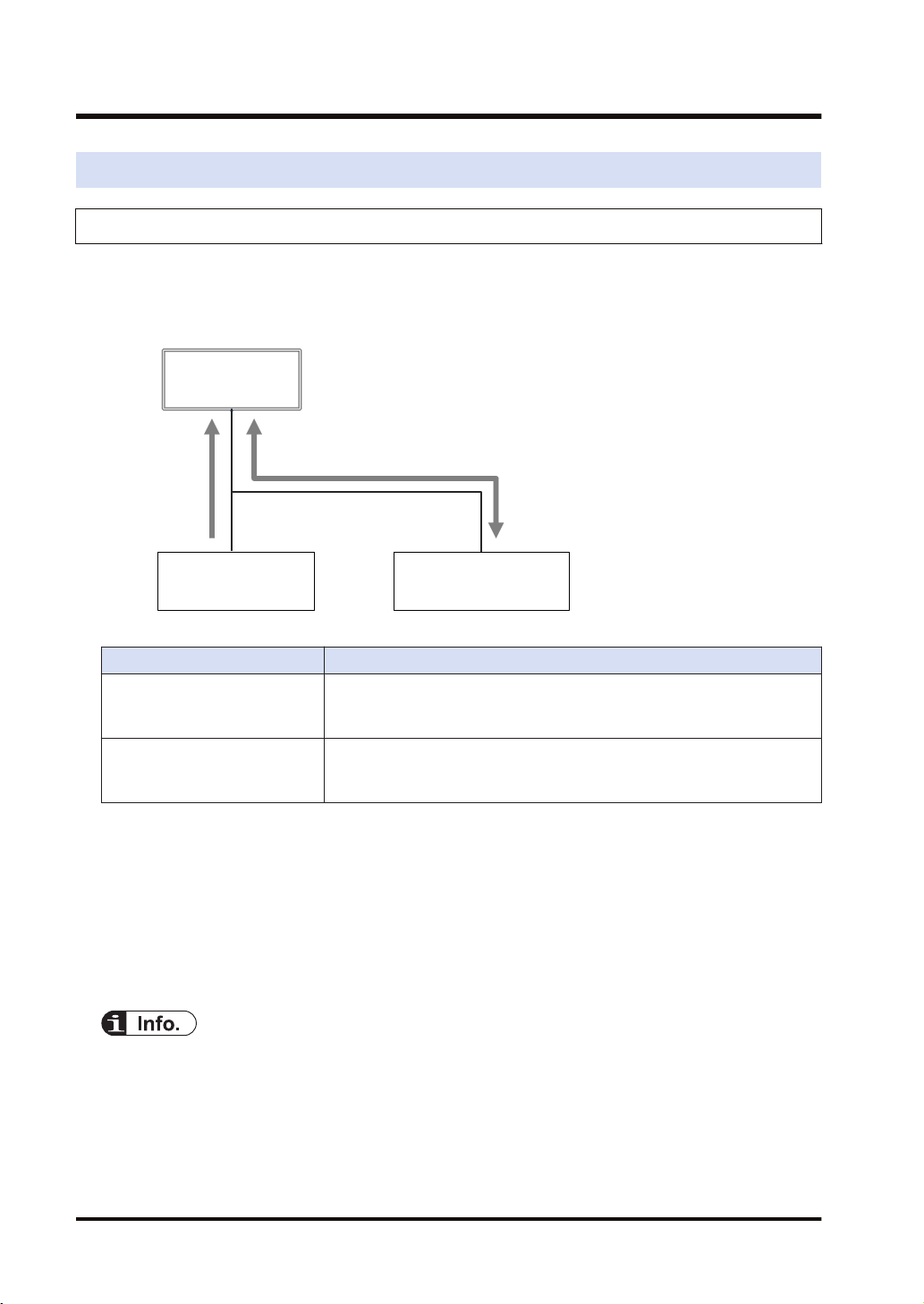
2.2.1 Connection using FP0H as originator
■
Illustration of operation
The FP0H establishes connections with targets registered in Scan List and performs the cyclic
communication.
Description
Input direction
(Direction from Target to
Originator)
Output direction
(Direction from Originator to
Target)
■
Settings
Data is sent from targets to the FP0H periodically.
Data is sent from the FP0H to targets periodically.
Register target low-order PLCs and I/O devices in "Scan List" of FP0H and register connection
information. The registration is made for each target.
Register the following information in the connection information.
● Connected target information (IP address, Tag/Instance)
● Data area and size that corresponds to Tag/Instance
● Cyclic communication information (RPI, Communication method)
● Scan List is a list for setting the connection information with "Target". Use Programming
software FPWIN GR7 for the registration.
● For registering other companies' EtherNet/IP devices in Scan List, the EDS files of those
devices are required. Communication parameters that can be set in each device are defined in
the EDS files.
2-6 WUME-FP0HEIP-05
High-order PLC
(FP7)
Originator
Connection 1
Sends data to High-order PLC.
FP0H
Input Only
Target
2.2 Cyclic Communication of FP0H
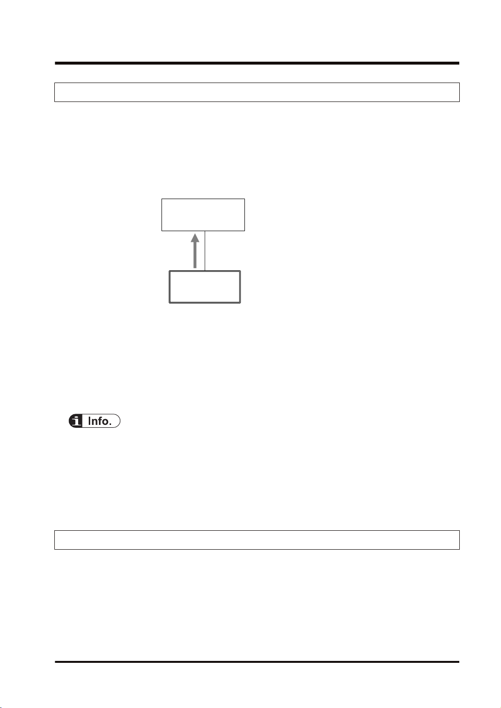
2.2.2 Connection Using FP0H as Target
■
Illustration of operation
● The high-order PLC (FP7) (originator) makes a connection for the registered tag/instance.
● When the FP0H is used as target, only the transmission to originator (Input Only) is
available.
● Once the connection from an originator is established, the FP0H sends data to the originator
from the buffer for the cyclic communication periodically.
■
Settings
Register the tag/instance information in the "I/O map" of the FP0H.
● The tag/instance information is registered for each originator.
● The tag/instance information includes the following information.
• Connected tag/instance
• Data area and size that corresponds to Tag/Instance
● I/O map is a list for setting the connection information with "Originator". Use Programming
software FPWIN GR7 for the registration.
● The EDS file of FP0H can be downloaded from our download center.
https://industrial.panasonic.com/ac/j/dl_center/
● For using the FP0H as a target, the both methods, tag and instance, are available. However,
the selectable instance IDs for the instance method are 100 to 199.
2.2.3 Example of Configuration When FP0H is Originator and Target
■
Illustration of operation
Example of Configuration When FP0H is Originator and Target In the example, the FP0H uses
five connections.
WUME-FP0HEIP-05 2-7
FP7
Target 1
Low-order PLC
Input Only
I/O device B
Exclusive Owner
Target 2 Target 3
Target 4
Connection 1
Sends data to FP7.
Connection 2
Sends data from FP7.
Connection 3
Receives data.
Connection 4
Receives data.
Connection 5
Sends and Receives data.
FP0H
FP0H
I/O device A
Input Only
Originator 1
2.2 Cyclic Communication of FP0H
■
Target settings
Set the FP0H as below to send/receive data with the high-order FP7.
● Register the FP7 in the scan list and set the connection information.
● Register the I/O map for connecting the FP7 and set the tag/instance information.
■
Originator settings
Set the FP0H as below to receive data from low-order devices (low-order PLC, I/O devices A
and B). When the connection with a target is "Exclusive Owner", data can be sent and received.
● Register the low-order PLC, I/O devices A and B in the scan list and set the connection
information.
2-8 WUME-FP0HEIP-05

3 Setting Procedure
3.1 Overview of Settings...........................................................................3-2
3.1.1 System Example .............................................................................. 3-2
3.1.2 Setting Procedure ............................................................................ 3-2
3.2 Initial Setting of Ethernet /IP ...............................................................3-4
3.2.1 Ethernet Settings ............................................................................. 3-4
3.2.2 Starting EtherNet/IP Setting Screen ................................................ 3-5
3.2.3 EtherNet/IP Basic Configuration ...................................................... 3-5
3.2.4 Items of Ethernet /IP Basic Configuration ........................................ 3-6
3.3 Settings of Connection Using FP0H as Originator..............................3-8
3.3.1 Settings ............................................................................................ 3-8
3.3.2 Registering EDS File of Target Device............................................. 3-8
3.3.3 Adding Target in Scan List ............................................................... 3-9
3.3.4 Setting IP Address of Target ............................................................ 3-10
3.3.5 Setting Tag/Instance ........................................................................ 3-11
3.3.6 Specifying Data Area Corresponding to Tag/Instance ..................... 3-13
3.3.7 Reference: Setting of Target "FP0H(B)"........................................... 3-15
3.4 Settings of Connection Using FP0H as Target ...................................3-16
3.4.1 Settings ............................................................................................ 3-16
3.4.2 Adding I/O Map to Scan List ............................................................ 3-16
3.4.3 Registering Tag Name/Instance ID .................................................. 3-17
3.4.4 Registering Data Area Corresponding to Tag/Instance.................... 3-18
3.4.5 Reference: Setting of Originator "FP7" ............................................ 3-19
3.5 Confirmation of Load Factor Calculation.............................................3-21
3.5.1 Load Factor Calculation ................................................................... 3-21
3.5.2 Displaying Load Factor Calculation ................................................. 3-21
3.6 Saving EtherNet/IP Settings ...............................................................3-22
3.6.1 Saving EtherNet/IP Settings in Project ............................................ 3-22
3.6.2 Saving/Reading EtherNet/IP Settings in File ................................... 3-22
3.6.3 Writing EtherNet/IP Settings to FP0H .............................................. 3-23
WUME-FP0HEIP-05
3-1
: Opens connection. : Sends cyclic data.
FP0H(A)
IP:192.168.1.5
LD40
LD49
LD40
LD49
LD30
LD39
FP0H(B)
FP7
LD30
LD39
IP:192.168.1.6
IP:192.168.1.7
Originator
Originator
Target
Target
Tag_Test2
Tag_Test1
Tag_Test2
Tag_Test1
3.1 Overview of Settings
3.1 Overview of Settings
3.1.1 System Example
This chapter describes the case of setting FP0H(A) in the following system example.
Operation of FP0H(A)
● The data received from the Tag (Tag_Test2) of the FP0H(B) is stored in the data area (LD40
to 49) of the FP0H(A). The FP0H(A) is the originator for the FP0H(B).
Add the FP0H(B) in the scan list and make the connection setting.
● The data stored in the data area (LD30 to 39) of the FP0H(A) is sent to the FP7. The
FP0H(A) is the target for the FP7.
Add the tag (Tag_Test1) in the I/O map and register the data area.
● The number of used connections totals two.
3.1.2 Setting Procedure
The setting procedure is as follows.
Use Programming software Control FPWIN GR7 (hereinafter referred to FPWIN GR7) for the
settings.
3-2 WUME-FP0HEIP-05

3.1 Overview of Settings
Item Outline of operation Reference
1 Initial setting of Ethernet /IP
Settings of connection using
2
FP0H as originator
Settings of connection using
3
FP0H as target
Confirmation of load factor
4
calculation
5 Saving of Ethernet/IP settings Save the settings of EtherNet/IP. "P.3-22"
Enable EtherNet/IP communication in the "Ethernet settings"
and make the initial setting of EtherNet/IP.
Register EDS Files of target devices. "P.3-8"
Add targets in the scan list. "P.3-9"
Register connection information (such as connected targets,
cyclic communication, corresponding data areas and sizes).
Add I/O map in the scan list. "P.3-16"
Register the tag/instance information connected. "P.3-17"
Confirm the load factor calculation is 100% or less. "P.3-21"
"P.3-4"
"P.3-10"
WUME-FP0HEIP-05 3-3
3.2 Initial Setting of Ethernet /IP
3.2 Initial Setting of Ethernet /IP
3.2.1 Ethernet Settings
This is the setting for the communication function via LAN ports including EtherNet/IP. Use
FPWIN GR7 for the setting. The following procedure is explained on the condition that FPWIN
GR7 has already started.
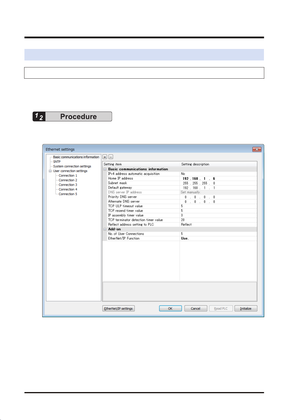
1. Select Option>Ethernet settings from the menu bar.
The "Ethernet settings" dialog box appears.
2. As necessary, change "Home IP address" and "No. of User Connections".
In this example, "IP address = 192.168.1.6", and "No. of User Connections = 5".
3. Change the setting of "EtherNet/IP Function" to "Use".
4. Press the [OK] button.
3-4 WUME-FP0HEIP-05
3.2 Initial Setting of Ethernet /IP
● The number of connections available for EtherNet/IP is (9-"No. of user connection"). When the
value is "5" which is initial value, the number of connections available for EtherNet/IP is "4".
● If the setting of “EtherNet/IP Function” is changed to"" "Not use", the EtherNet/IP setting
information will be cleared.
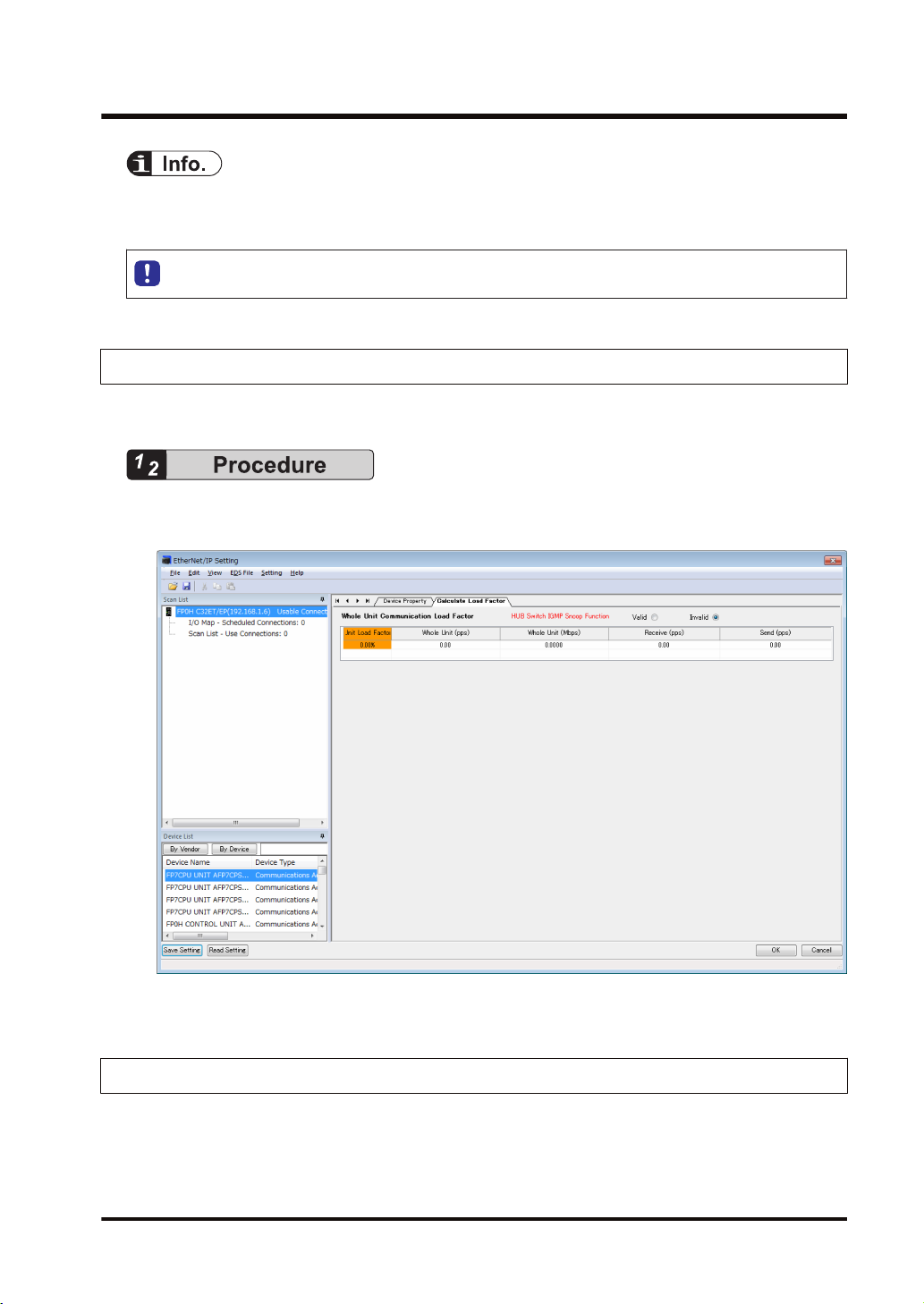
3.2.2 Starting EtherNet/IP Setting Screen
The following procedure is explained on the condition that FPWIN GR7 has already started.
1. Select Option>EtherNet/IP Settings from the menu bar.
The EtherNet/IP setting screen appears.
The following description assumes that the EtherNet/IP setting screen has been activated.
3.2.3 EtherNet/IP Basic Configuration
Make the EtherNet/IP basic configuration. The following procedure is explained on the
assumption that the EtherNet/IP setting screen has been activated.
WUME-FP0HEIP-05 3-5
3.2 Initial Setting of Ethernet /IP
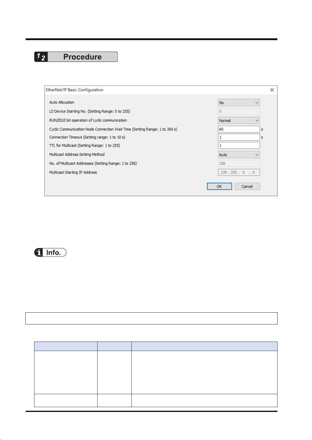
1. Select Setting>EtherNet/IP Basic Configuration from the menu bar.
The EtherNet/IP Basic Configuration dialog box appears.
2. Change "Auto Allocation", "RUN / IDLE bit operation of cyclic communication", "Connection
Timeout" as necessary.
In this example, they are set as follows: "Auto Allocation = No", "RUN/IDLE bit operation of
cyclic communication = Normal", and "Connection Timeout = 1 s".
3. Press the [OK] button.
● When allocating devices manually, set "Auto Allocation" to "No".
● For performing operation check, set "RUN/IDLE bit operation of cyclic communication" to
"Limited". When selecting "Normal", the RUN/IDLE bit of the FP0H does not turn "ON" unless
the communications with all the targets registered in the scan list are established.
● The "Connection Timeout" can be set with the unit firmware Ver.1.7 or later.
3.2.4 Items of Ethernet /IP Basic Configuration
■
Settings relating to cyclic communication operation
Item Default Description
Set whether to use the automatic allocation of devices or not (Yes/
No).
Auto Allocation Yes
LD Device Starting No. 0
Auto Allocation
"Yes":
Auto Allocation "No": Devices are allocated manually.
Set the starting device number to be allocated at the time of the
device automatic allocation.
Devices for the I/O map setting and
connection setting are automatically
allocated.
3-6 WUME-FP0HEIP-05
 Loading...