

Panasonic AD50F-EG Service Manual
Service Manual
Colour Television EURO 3HW Chassis
TX-25AD50F TX-29AD50F
Safety
Specifications
Block Diagram(Video/Audio)
Block Diagram(Control)
Parts List
Service Information
PCB view(B)
PCB view(D)
PCB view(E)
PCB view(F)
PCB view(H)
PCB view(M)
T B
T B
Adjustments
Self Check
Service Hints
Mechanical View
Disassembly
Location of Controls
Waveforms
B Schematic
D Schematic
E Schematic
F Schematic
H Schematic
M Schematic
Notes
Service Support
About....
GO BACK
EXIT
PCB view(Y)
Y Schematic

ORDER NO. SM-96050
Service Manual
Colour Television
TX-29AD50F
TX-25AD50F
EURO-3H Chassis
Specifications
(Information in brackets { } refers to TX-25AD50F)
Power Source : 220 - 240 V AC, 50Hz
Power Consumption : 159W {149W}
Aerial Impedance : 75W unbalanced, Coaxial Type
Receiving System : PAL B/G, D/K, I, H, PAL - 60
Receiving Channels : VHF E2 - E12
VHF H1 - H2 (ITALY) VHF A - H (ITALY)
VHF R1 - R2 VHF R3 - R5
VHF R6 - R12 UHF E21 - E69
CATV (S01 - S05) CATV S1 - S10 (M1 - M10)
CATV S11 - S20 (U1 - U10) CATV S21 - S41 (HYPERBAND)
Intermediate Frequency :
Video 38.9MHz,34MHz
Sound 32.9MHz,33.4MHz
Colour 34.65MHz,34.47MHz,34.5MHz
Video / AudioTerminals
AUDIO MONITOR OUT Audio (RCA x 2) 500 mV rms 1kW
AV1 INVideo (21 pin ) 1 Vp-p 75W
AV1 OUT Video (21 pin ) 1 Vp-p 75W
AV2 INVideo (21 pin ) 1 Vp-p 75W
AV2 OUT Video (21 pin ) 1 Vp-p 75W
AV3 INS-Video IN Y : 1 Vp-p 75W
High Voltage : 30.5 kV "1kV at zero beam current
Picture Tube : A68ESF002X43 72 cm
Audio Output :
Internal Speaker 2 x 20W (Left/Right)(Music Power)
Headphones 8 W Impedance
Accessories supplied : Remote Control
Dimensions :
Height : 570mm {510mm}
Width : 698mm {625mm}
Depth : 483mm {468mm}
Net Weight 37kg {31kg}
Specifications are subject to change without notice.
Weight and dimensions shown are approximate.
SECAM B/G, D/K, L/L'
M.NTSC, NTSC (AV Only)
33.16MHz,32.4MHz
40.4MHz,34.05MHz,33.05MHz
Audio (21 pin ) 500 mV rms 10kW
RGB (21 pin )
Audio (21 pin ) 500 mV rms 1kW
Audio (21 pin ) 500 mV rms 10 kW
S-Video IN Y : 1 Vp-p 75W
(21 pin ) C : 0.3 Vp-p 75W
Audio (21 pin ) 500 mV rms 1kW
Selectable output (21 pin )
(4-pin ) C : 0.3 Vp-p 75W
Audio (RCA x 2) 500 mV rms 10kW
Video (RCA x 1) 1 Vp-p 75W
{A59ESF002X43 63 cm}
110_ deflection
25W (3D Bass)(Music Power)
8 W Impedance
2 x R6 (UM3) Batteries
Technische Daten
(Werte in klammern { } gelten nur fur TX-25AD50F)
Netzpannung : 220 - 240 V AC, 50Hz
Leistungsaufnahme : 159W {149W}
Antennenimpedanz : 75W asymmetrisch, Koaxial- Typ
Empfangssystem : PAL B/G, D/K, I, H, PAL - 60
Empfangsbereiche : VHF E2 - E12
VHF H1 - H2 (ITALY) VHF A - H (ITALY)
VHF R1 - R2 VHF R3 - R5
VHF R6 - R12 UHF E21 - E69
CATV (S01 - S05) CATV S1 - S10 (M1 - M10)
CATV S11 - S20 (U1 - U10) CATV S21 - S41 (HYPERBAND)
Zwischenfrequenz :
Video 38.9MHz,34MHz
Sound 32.9MHz,33.4MHz
Colour 34.65MHz,34.47MHz,34.5MHz
Video / Audio Anschlüsse :
AUDIO MONITOR AUSGANG Audio (RCA x 2) 500 mV rms 1kW
AV1 EINGANG Video (21 pin ) 1 Vp-p 75W
AV1 AUSGANG Video (21 pin ) 1 Vp-p 75W
AV2 EINGANG Video (21 pin ) 1 Vp-p 75W
AV2 AUSGANG Video (21 pin ) 1 Vp-p 75W
AV3 EINGANG S-Video IN Y : 1 Vp-p 75W
Hochspannung : 30.5 kV "1kV bei Nullstrahlstom
Bildrohre : A68ESF002X43 72 cm
Ton Ausgangsleistung :
Einbaulautsprecher 2 x 20W (Links/Rechts)(Musikleistung)
Kopfhörer 8 W Impedanz
Mitgel. Zubehör Fernbedienung
Abmessungen :
Höhe : 570mm {510mm}
Breite : 698mm {625mm}
Tiefe : 483mm {468mm}
Gewicht 37kg {31kg}
Änderungen der technischen Daten vorbehalten.
Gewichte und Abmessungen sind Näherungsangaben.
SECAM B/G, D/K, L/L'
M.NTSC, NTSC (nur AV Eingang)
33.16MHz,32.4MHz
40.4MHz,34.05MHz,33.05MHz
Audio (21 pin ) 500 mV rms10kW
RGB (21 pin )
Audio (21 pin ) 500 mV rms1kW
Audio (21 pin ) 500 mV rms 10 kW
S-Video IN Y : 1 Vp-p 75W
(21 pin ) C : 0.3 Vp-p 75W
Audio (21 pin ) 500 mV rms1kW
Selectable output (21 pin )
(4-pin ) C : 0.3 Vp-p 75W
Audio (RCA x 2) 500 mV rms10kW
Video (RCA x 1) 1 Vp-p 75W
{A59ESF002X43 63 cm}
110_Ablenkung
25W (3D Bass)(Musikleistung)
8 W Impedanz
2 x R6 (UM3) Batterien

CONTENTS
INHALT
SAFETY PRECAUTIONS 2
LOCATION OF CONTROLS 4
SERVICE HINTS 4
ADJUSTMENTS 5
SELF CHECK 9
WAVEFORM PATTERN TABLE 11
CONDUCTOR VIEWS 12
BLOCK DIAGRAM 19
SCHEMATIC DIAGRAMS 23
PARTS LOCATION 30
REPLACEMENT PARTS LIST 31
SAFETY PRECAUTIONS
General Guide Lines
1. It is advisable to insert an isolation transformer in the AC
supply before servicing a hot chassis.
2. When servicing, observe the original lead dress in the high
voltage circuits. If a short circuit is found, replace all parts
which have been overheated or damaged by the short circuit.
3. After servicing, see that all the protective devices such as
insulation barriers, insulation papers, shields and isolation RC combinations are correctly installed.
4. When the receiver is not being used for a long period of time,
unplug the power cord from the AC outlet.
5. Potentials as high as 31.5kV are present when this receiver is
in operation. Operation of the receiver without the rear cover
involves the danger of a shock hazard from the receiver
power supply. Servicing should not be attempted by anyone
who is not familiar with the precautions necessary when
working on high voltage equipment. Always discharge the
anode of the picture to the chassis before handling the tube.
6. After servicing make the following leakage current checks to
prevent the customer from being exposed to shock hazards.
LEAKAGE CURRENT COLD CHECK
1. Unplug the AC cord and connect a jumper between the two
prongs of the plug.
2. Turn on the receiver's power switch.
3. Measure the resistance value with an ohmmeter, between
the jumpered AC plug and each exposed metallic cabinet
part on the receiver, such as screw heads, aerials ,
connectors, control shafts etc. When the exposed metallic
part has a return path to the chassis the reading should be
between 4M ohm and 20M ohm. When the exposed metal
does not have a return path to the chassis the reading must
be infinite.
SICHERHEITSVORKEHRUNGEN 2
LAGE DER EINSTELLREGLER 4
WARTUNGSHINWEISE 4
JUSTIERUNGEN 5
SELBSTDIAGNOSE 9
SIGNAL TABELLE 11
ANSICHT DER LEITERBAHNEN 12
SCHALTBILD BLOCK 19
SCHALTBILD SCHEMA 23
EXPLOSIONSZEICHNUNG 30
ERSATZTEILLISTE 31
SICHERHEITSVORKEHRUNGEN
Allgemeine Richtlinien
1. Es ist empfehlenswert einen Trenntransformator in die
Stromversorgung zu schalten, bevor Reparaturen an einem
Gerät vorgenommen werden, dessen Chassis unter
Spannung steht.
2. Bei der Durchführung von Servicearbeiten dürfen die
ursprünglichen Kabelanschlüsse nicht vertauscht werden.
Dies gilt insbesondere für die Anschlüsse im
Hochspannungsteil. Hat sich ein Kurzschlu_ ereignet, dann
sind alle Teile, an denen Spuren von Überhitzung sichtbar
sind, auszuwechseln.
3. Nach Beenden der Servicearbeiten ist sicherzustellen, da_
alle Sicherheitsvorrichtungen, wie Isolationsstege,
Isolationspapiere, Abschirmungen und Isolations -R/CGlieder wieder richtig eingesetzt sind.
4. Wenn der Fernseher während längerer Zeit nicht in Betrieb
gesetzt wird, sollte der Netzstecker aus der Netzsteckdose
gezogen werden.
5. Im Betrieb sind Spannungen bis zu 31.5kV in diesem Gerät
vorhanden. Die Inbetriebnahme des Fernsehers ohne
aufgesetzte Rückwand bringt die Gefahr eines elektrischen
Schlages von der Fernseher - Stromversorgung mit sich.
Servicearbeiten solten daher auch nie durch Personen
versucht werden, die nicht in vollem Umfang mit den
Sicherheitsvorkehrungen beim Umgang mit
Hochspannungsgeräten vertraut sind. Vor der Handhabung
mit der Bildröhre ist die Anode der Bildröhre immer an dem
Empfängerchassis zu entladen.
6. Nach Beenden der Servicearbeiten sind die folgenden
Kriechstrom-Prüfungen durchzuführen, um den Kunden vor
der Gefahr eines elektrischen Schlages zu schützen.
MESSUNG DES ISOLATIONSWIDERSTANDES IM
ABGESCHALTETEN ZUSTAND
1. Den Netsztecker aus der Netzsteckdose ziehen und die
beiden Steckerstifte kurzschlie_en.
2. Den Geräteschalter des Fernsehgerätes einschalten.
3. Mit einem Ohmmeter den Widerstandswert zwischen dem
überbrückten Netzstecker und jedem zugänglichen Metallteil
am Gehäuse des Fernsehgerätes, wie Schraubenköpfe,
Antennen, Achsen der Regler, Griffassungen usw messen.
Wenn ein zugängliches Metallteil keine Rückleitung zum
Chassis hat, mu_ die Anzeige unendlich betragen.
2
LEAKAGE CURRENT HOT CHECK
1. Plug the AC cord directly into the AC outlet. Do not use an
isolation transformer for this check.
2. Connect a 2kW 10W resistor in series with an exposed
metallic part on the receiver and an earth such as a water
pipe.
3. Use an AC voltmeter with high impedance to measure the
potential across the resistor.
4. Check each exposed Metallic part and check the voltage at
each point.
5. Reverse the AC plug at the outlet and repeat each of the
above measurements.
6. The potential at any point should not exceed 1.4 Vrms. In
case a measurement is outside the limits specified, there is a
possibility of a shock hazard, and the receiver should be
repaired and rechecked before it is returned to the customer.
HOT CHECK CIRCUIT
SCHALTUNGSAUFBAU FÜR PRUFUNG
IM EINGESCHALTETEN ZUSTAND
MESSUNG DES KRIECHSTROMS IM
EINGESCHALTETEN ZUSTAND
1. Den Netzstecker direkt in eine Netsteckdose stecken. Für
diese Messung keinen Trenntransformator verwenden.
2. Einen 2k W / 10W-Widerstand in Serie mit einem von au_en
zugänglichen Metallteil am Fernsehgerät und einer guten,
Erdung z.B Wasserleitung, anschlie_en.
3. Ein Wechselstrom-Voltmeter mit einem Me_bereich von
1000 Ohm.Volt oder grö_er verwenden, um die Spannung
über den Widerstand zu messen.
4. Jedes zugängliche Metallteil prüfen, und an jedem Punkt die
Spannung messen.
5. Den Netztecker umgekehrt in die Steckdose stecken und
jede der obigen Messungen wiederholen.
6. Die Spannung darf an keinem der Punkte 1.4V eff.
überschreiten. Wird dieser Wert nicht eingehalten, besteht
die Gefahr eines elektrischen Schlages, und das
Fernsehgerät sollte daher repariert und nachgeprüft werden,
bevor es an den Kunden zurückgegeben wird.
RÖNTGENSTRAHLUNG
ACHTUNG :
1. Potentielle Quellen von Röntgenstrahlung in Fernsehgeräten
sind das Hochspannungsteil und die Bildröhre.
2. Bei Verwendung eines Bildröhren-Prüfgerätes für den
Service ist sicherzustellen, da_ es für die Belastung von
31.5kV geeignet ist, ohne da_ eine Röntgenstrahlung
verursacht wird.
X-RADIATION WARNING
1. The potential sources of X-Radiation in TV sets are the high
voltage section and the picture tube.
2. When using a picture tube test jig for service ensure that the
jig is capable of handling 31.5kV without causing X-Radiation.
NOTE : It is important to use an accurate periodically calibrated high
voltage meter.
1. Set the brightness to minimum.
2. Measure the high voltage. The meter should indicate
30.5kV "1kV if the meter indication is out of tolerance,
immediate service and correction is required to prevent the
possibility of premature component failure.
3. To prevent any X-Radiation possibility, it is essential to use
the specified tube.
ANMERKUNG : Es ist wichtig, da_ ein präzises, regelmä_ig
geprüftes Voltmeter verwendet wird.
1. Helligkeit auf Minimum stellen.
2. Die Hochspannung messen. Die Anzeige des Instrumentes
sollte 30.5kV "1kV betragen. Falls die Anzeige diese
Toleranzgrenzen überschreitet, ist die sofortige Behebung
nötig, um die Möglichkeit vorzeitigen Komponentenausfalls
zu verhüten.
3. Um die Möglichkeit von Röntgenstrahlung zu begrenzen, ist
es wichtig, da_ nur die vorgeschriebene Bildröhre verwendet
wird.
3
Location Of Controls Lage der Einstellregler
SERVICE HINTS
How to remove the rear cover
1. Remove the 9 screws (A) as shown in Fig.3/Fig.4.
SERVICE HINWEISE
Entfernen Der Geräterückwand
1. Die 9 Schrauben (A) entfernen, siehe Abb.3/Abb.4.
Adjustment Procedure
The remote control is used for entering and storing adjustments, with the exception of cut-off adjustments which must always be done prior to
service adjustment. Perform adjustments in accordance with screen display. The display on the screen also specifies the CCU variants as
well as the approx. setting values. The adjustment sequence for the service mode is indicated below.
1. Set the Bass to maximum position, set the Treble to minimum
position, press and hold the Reveal button on the remote
control and at the same time press the -/v button on the
customer controls at the front of the TV, this will place the TV
into the Service Mode.
2. Press the RED / GREEN buttons to step up / down through
the functions.
NOTE: This TV also has the option of using a Memory Pack which enables you to copy the preset TV channels into the Memory Pack and
then download them onto this or any other EURO-3 TV set.
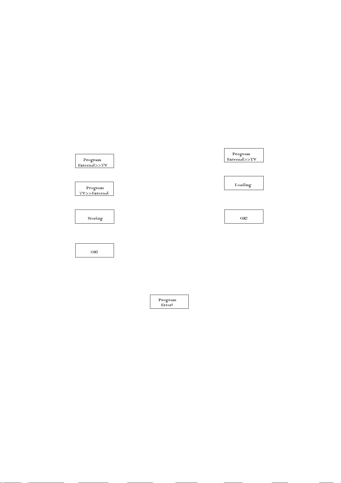
TV to Memory Pack process
1. Plug the memory pack into the AV2 21 pin terminal at the
back of the TV and switch the TV on.
2. Go into the Service Mode as explained above. The screen
will show:-
3. Press the blue button on the remote control. The screen will
show:-
4. Press the STORE button on the TV. The screen will show:-
3. Press the YELLOW / BLUE buttons to alter the function
values.
4. Press the STORE button after each adjustment has been
made to store the required values.
5. To exit the Service Mode press the Normalisation button..
1. Plug the memory pack into the AV2 21 pin terminal at the
back of the TV and switch the TV on.
2. Go into the Service Mode as explained above. The screen
will show:-
3. Press the STORE button on the TV. The screen will show:-
4. All the tuning information stored inside the Memory Pack will
now be transferred to the TV. This process will take 2-3
minutes to complete and when finished the screen will show:-
5. All the tuning information stored inside the TV will now be
transferred to the Memory Pack. This process will take 2-3
minutes to complete and when finished the screen will show:-
Memory Pack to TV Process
5. The tuning information from the Memory Pack has now been
copied into the TV.
6. To exit from the Service Mode press the Normalisation
button.
7. The process has now been completed and the Memory Pack
can now be removed.
Errors
If an error occurs while using the Memory Pack the TV will detect this and the screen will show:-
If this happens then press the Normalisation button and repeat the process that was being used. If the errors continue to occur then check the
connectors between the TV and the memory pack and check the 9V battery inside the memory pack.
ABGLEICHVERFAHREN
Die Fernbedienung dient zum Eingeben und Abspeichern der Einstellwerte, mit Ausnahme der Sperrpunkteinstellung, die grundsätzlich vor
den hier beschriebenen Einstellungen vorgenommen werden muss. Die Einstellung erfolgt entsprechend dem Bildschirm-Display. Auf dem
Bildschirm-Display erscheinen auch die CCU-Varianten sowie die ungefähren Einstellwerte. Die Einstellfolge für den Service-Modus ist
nachstehend beschrieben.
1. Um in den Service-Mode zu gelangen, gehen sie bitte wie
folgt vor.
a) Stellen sie im Toneinstellungs-Menü die Bässe auf
Maximum und die Höhen auf Minimum.
b) Halten sie die REVEAL-Taste auf der Fernbedienung
gedrückt und drücken zusätzlich die Taste -/v im Bedienteil
des TV-Gerätes. Auf dem Bildschirm erscheint die
entsprechende Anzeige für den Service-Mode.
HINWEIS: Dieses FS-Gerät bietet auch die Möglichkeit eines Memory Pack, mit dem Sie die gewählten Fernsehkanäle abspeichern und auf
jedes beliebige EURO3 FS-Gerät umkopieren können.
Kopieren der Einstelldaten vom FS-Gerät in das Memory Pack
1. Das Memory Pack in die AV2-Buchse an der Rückseite des
FS-Gerätes stecken und das Gerät einschalten.
2. Wie schon oben beschrieben auf Service-Modus
umschalten. Auf dem Bildschirm erscheint:
3. Nun die blaue Taste an der Fernbedienung betätigen. Auf
dem Bildschirm erscheint:
4. Die Taste STORE am Fernseher drücken. Der Bildschirm
meldet nun:
2. Die einzelnen Funktionen mit Hilfe der ROTEN und
GRÜNEN Taste anwählen.
3. Mit der GELBEN und BLAUEN Taste die Werte der
einzelnen Funktionen ändern.
4. Nach jeder Einstellung die Taste STR auf der Fernbdienung
oder am Bedienfeld drücken, um die geänderten Werte
abzuspeichern.
5. Zum Verlassen des Service-Modus die "N"-Taste auf der
Fernbdienung drücken
1. Das Memory Pack in die AV2-Buchse an der Rückseite des
FS-Gerätes stecken und das Gerät einschalten.
2. Wie schon oben beschrieben auf Service-Modus
umschalten. Auf dem Bildschirm erscheint:
3. Die Taste STORE am Fernseher drücken. Der Bildschirm
meldet nun:
4. Die im Memory Pack abgespeicherten Einstelldaten werden
nun in das FS-Gerät überspielt. bei aggeschlossener
Datenübertragung meldet der Bildschirm:
5. Die im FS-Gerät abgespeicherten Kanal-Einstelldaten
werden nun in das Memory Pack überspielt. bei
abgeschlossener Datenübertragung meldet der Bildschirm:
Kopieren der Einstelldaten vom Memory Pack in das FS-Gerät
5. Die Kanal-Einstelldaten sind damit vom Memory Pack in das
FS-Gerät überspielt.
6. Zum Verlassen des Service-Modus die "N"-Taste auf der
Fernbdienung drücken
7. Der Kopiervorgang ist somit abgeschlossen, und das
Memory Pack kann von der Steckerleiste abgezogen
werden.
Fehler
Falls beim Gebrauch des Memory Packs Fehler aufreten, zeigt das FS-Gerät dies auf dem Bildschirm mit der folgenden Meldung an:
In diesem Fall muss der Service-Modus durch Drücken der "N"-Taste auf der Fernbedienung verlassen und anschliessend der Vorgang
wiederholt werden. Falls weiterhin Fehlermeldungen erscheinen, müssen die Anschlusskontakte zwischen FS-Gerät und Memory Pack
sowie die 9V Batterie im Memory Pack kontrolliert werden.
6

Alignment Settings
(The figures used below are nominal and used for representative purposes only)
Alignment Function Settings / Special features
Vertical amplitude
V-AMP
026
Optimum setting
Vertical linearity
V-Pos.
Horizontal amplitude
Horizontal position
EW-amplitude
EW-amplitude
Trapezium-comp
V-LIN
022
V-POS
005
Optimum setting
H-AMP
045
H-POS
032
Optimum setting
E/W-AMP 1
063
Optimum setting
E/W-AMP 2
021
Optimum setting
TRAPEZ-1
004
Vert. DC.
Text Position
Cutoff
Cutoff RGB
White RGB
Sub Brightness
VERT. D.C.
008
TEXT POSITION
060
- - -
CUTOFF RGB
032 032 032
WHITE RGB
032 032 032
SUB BRIGHT
000
Optimum setting
Enter Service Mode and step through to
Cutoff, connect an oscilloscope to the Blue
Cathode and adjust the screen VR of the FBT to get
150_5V at the base of the Cutoff pulse.
Press the GREEN button to step through the
settings. Adjust for optimum.
Press the GREEN button to step through the
settings. Adjust for optimum.
Optimum setting
7

Abgleichtabelle
(Die angegebenen Werte sind Mittelwerte und Können individuell nach oben oder unten nach dem korrekten Abgleich abweichen)
Abgleichfunktion Einstellung/Besondere Merkmale
Vertikale Amplitude
V-AMP
026
Optimale Einstellung
Vertical linearität
V-Pos.
Horizontale Amplitude
Horizontale position
OW-amplitude
OW-amplitude
Trapez-Kompensation
Vert. DC.
V-LIN
022
V-POS
005
Optimale Einstellung
H-AMP
045
H-POS
032
Optimale Einstellung
E/W-AMP 1
063
Optimale Einstellung
E/W-AMP 2
021
Optimale Einstellung
TRAPEZ-1
004
VERT. D.C.
008
Text Position
TEXT POSITION
060
Cutoff - - - Den Service Mode aktivieren und auf Cutoff gehen.
Cutoff RGB
CUTOFF RGB
032 032 032
White RGB
WHITE RGB
032 032 032
Grundhelligket
SUB BRIGHT
000
Optimale Einstellung
Oscilloscope an Blaukathode anschliessen und mit
dem "Screen" -Regler am Zeilentrafo die untere
Spitze des Cutoff-Pulses auf 150V+/- 5V einstellen.
Die Einstellungen mit Hilfe der GRÜNEN Taste
anwählen. Optimale Einstellung.
Die Einstellungen mit Hilfe der GRÜNEN Taste
anwählen. Optimale Einstellung.
Optimale Einstellung
8
ADJUSTMENT PROCEDURE
Item/Preparation Adjustments
Supply Voltage Check
1. Receive a standard test pattern
2. Set the controls:
Brightness Minimum
Contrast Minimum
Volume Minimum
1. Confirm the following voltages.
E PCB D PCB
U5B 5 _ 0.5V U5A 5.1 +0.12/-0.1V
U8 8 _ 0.5V U5SB 5 _ 0.25V
U9 9 _ 0.5V U15 15 _ 0.7V
U12 11.8 _ 0.5V U16 18.2 _ 0.8V
U22 22.5 _ 1V
U38 19 _ 1V
U47 45.7 _ 2.5V
U150 150 _ 1V
U200 204 _ 10V
SELF CHECK
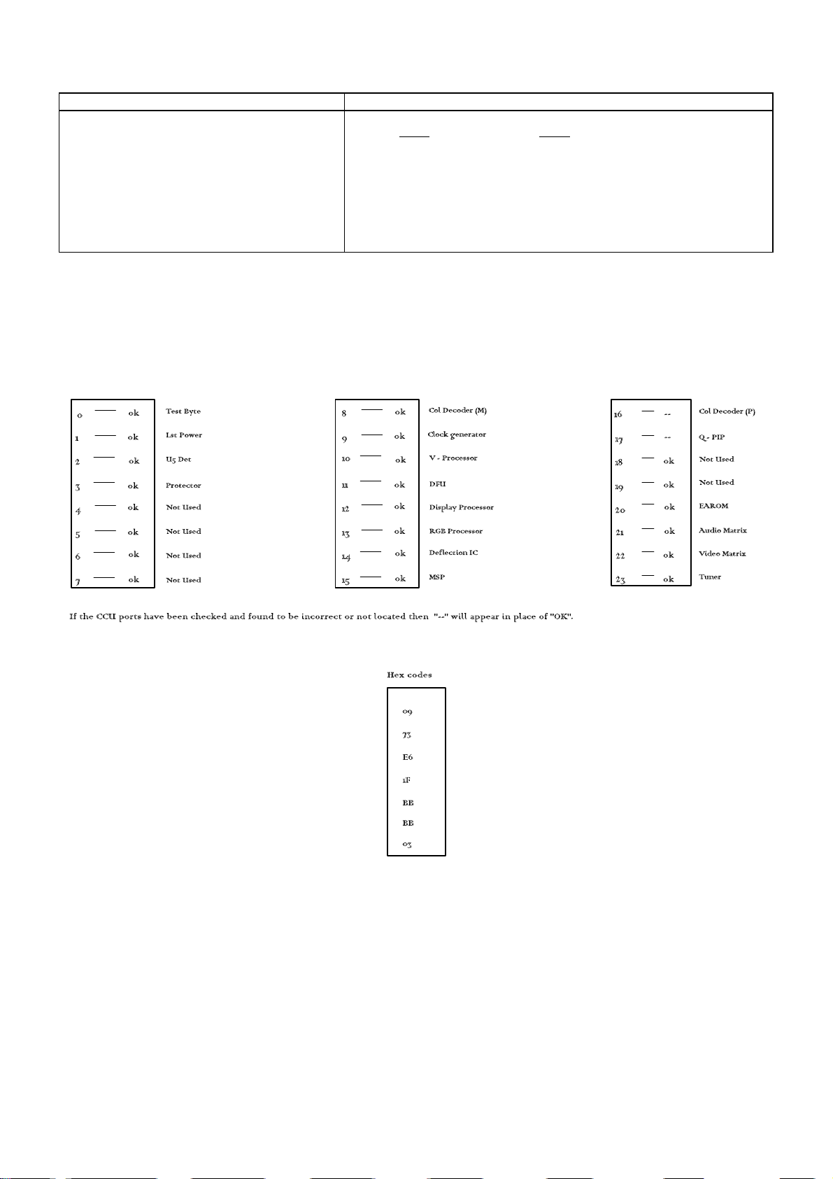
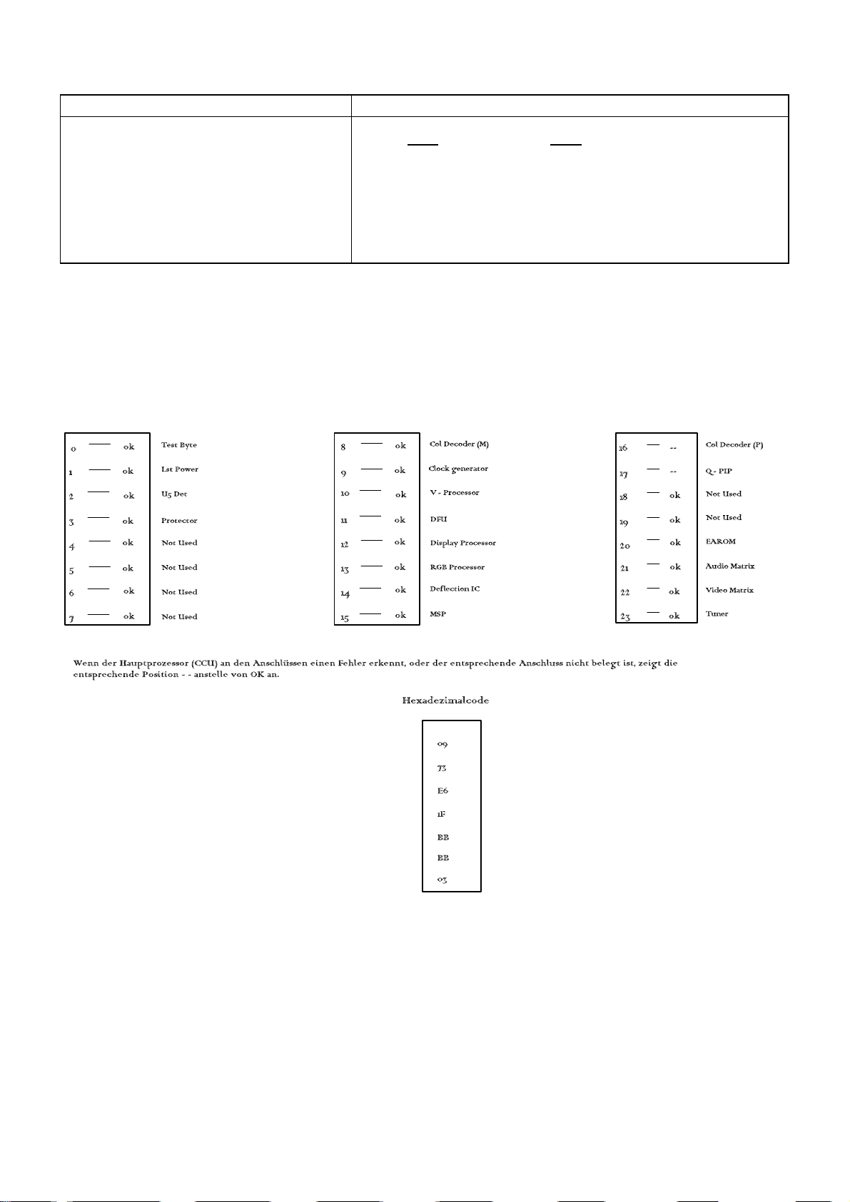
Self check is used to automatically check the Bus Lines and Hexadecimal code of the TV set.
To get into the Self Check mode press and hold the Status button on the Remote Control at the same time pressing the -/v button on the customer controls at the
front of the TV, and the screen will show:-
9
ABGLEICH
Vorbereitung Abgleich
Prüfen der Versorgungsspannung
1. Testbild empfangen.
2. Helligkeit auf Minimum
Kontrast auf Minimum
Lautstärke auf Minimum
1. Folgende Spannungen sind zu überprüfen :
E PCB D PCB
U5B 5 _ 0.5V U5A 5.1 +0.12/-0.1V
U8 8 _ 0.5V U5SB 5 _ 0.25V
U9 9 _ 0.5V U15 15 _ 0.7V
U12 11.8 _ 0.5V U16 18.2 _ 0.8V
U22 22.5 _ 1V
U38 19 _ 1V
U47 45.7 _ 2.5V
U150 150 _ 1V
U200 204 _ 10V
SELBSTDIAGNOSE
1) Die Selbstdiagnose dient zum automatischen Prüfen der Bus-Leitungen sowie des Hexadezimalcodes des FS-Geräts.
Um das Gerät in den Selbstdiagnose-Modus (Self-Check) zu versetzen, halten sie die STATUS-Taste auf der Fernbedienung gedrückt und drücken sie zusätzlich
die Taste -/v im Bedienteil des TV-Gerätes. Auf dem Bildschirm erscheinen folgende Informationen.
2) Nach der Selbstdiagnose wird das Gerät automatisch auf sämtliche werksseitigen Standardeinstellungen zurückgesetzt.
10
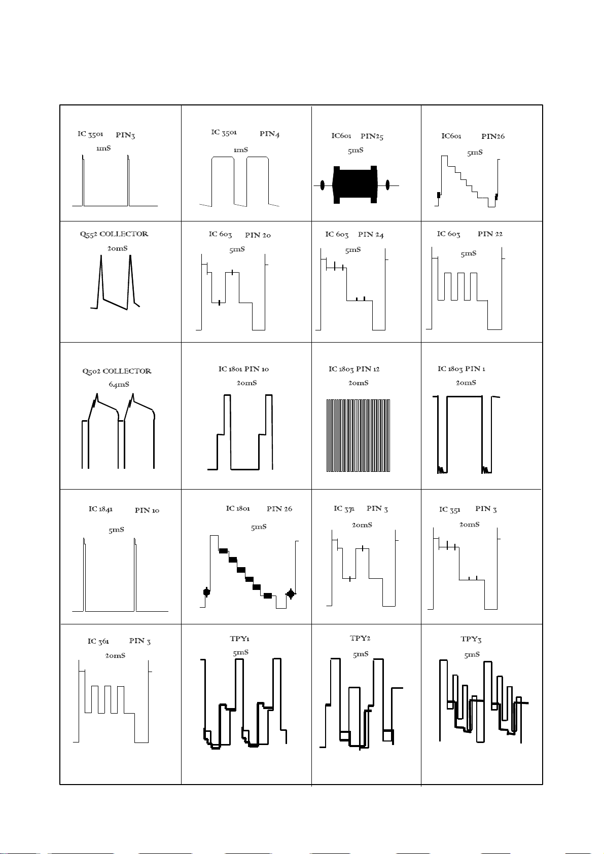
WAVEFORM PATTERN TABLE
SIGNAL TABELLE
11
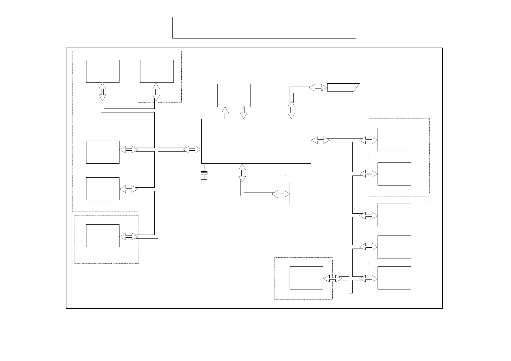
CONTROL BLOCK DIAGRAM
Tuner
E-Board
IC601
TDA9151
IC401
TDA9151
IC1552
SDA9257
F-Board
EAROM
IIC Bus1
X1101
EPROM
IC1105
Microcontroller
IC1101
M3L
IIC Bus4
F-Board
Mega-Text
IC3501
21 Pin AV2
IIC Bus2
IC2001
MSP3410
E-Board
IC603
TDA4780
IC1601
DFU
F-Board
IC1602
SDA9280
A.V.
Switching
H-Board
IC1701
V-Processor
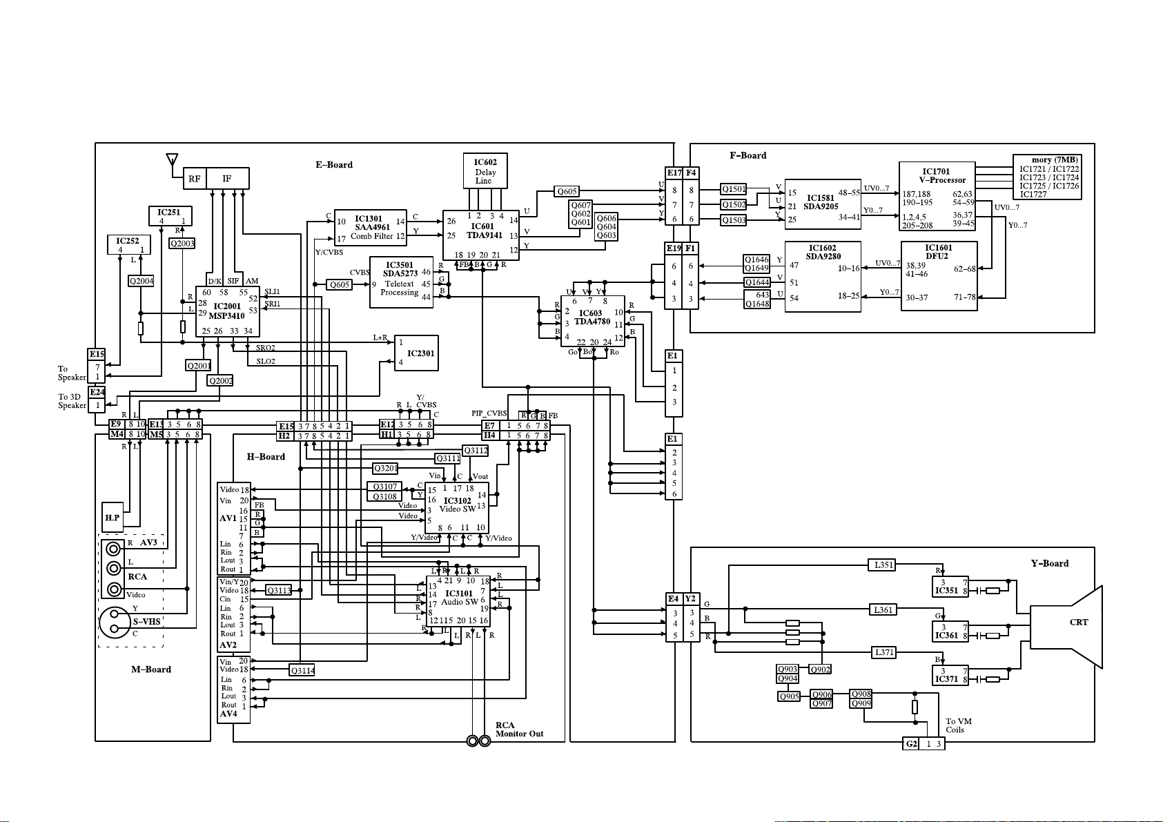
SCHEMATIC DIAGRAM FOR MODELS
TX-29AD50F
TX-25AD50F
(Euro-3H Chassis )
Notes
1. RESISTOR
All resistors are carbon ¼W resistor, unless marked as follows:
Unit of resistance is OHM (W) (K=1,000, M=1,000,000).
2. CAPACITORS
All capacitors are ceramic 50V, unless marked as follows:
Unit of capacitance is mF, unless otherwise stated.
3. COIL
Unit of inductance is mH, unless otherwise stated.
4. Components marked 'L' on the schematic diagram shows leadless parts.
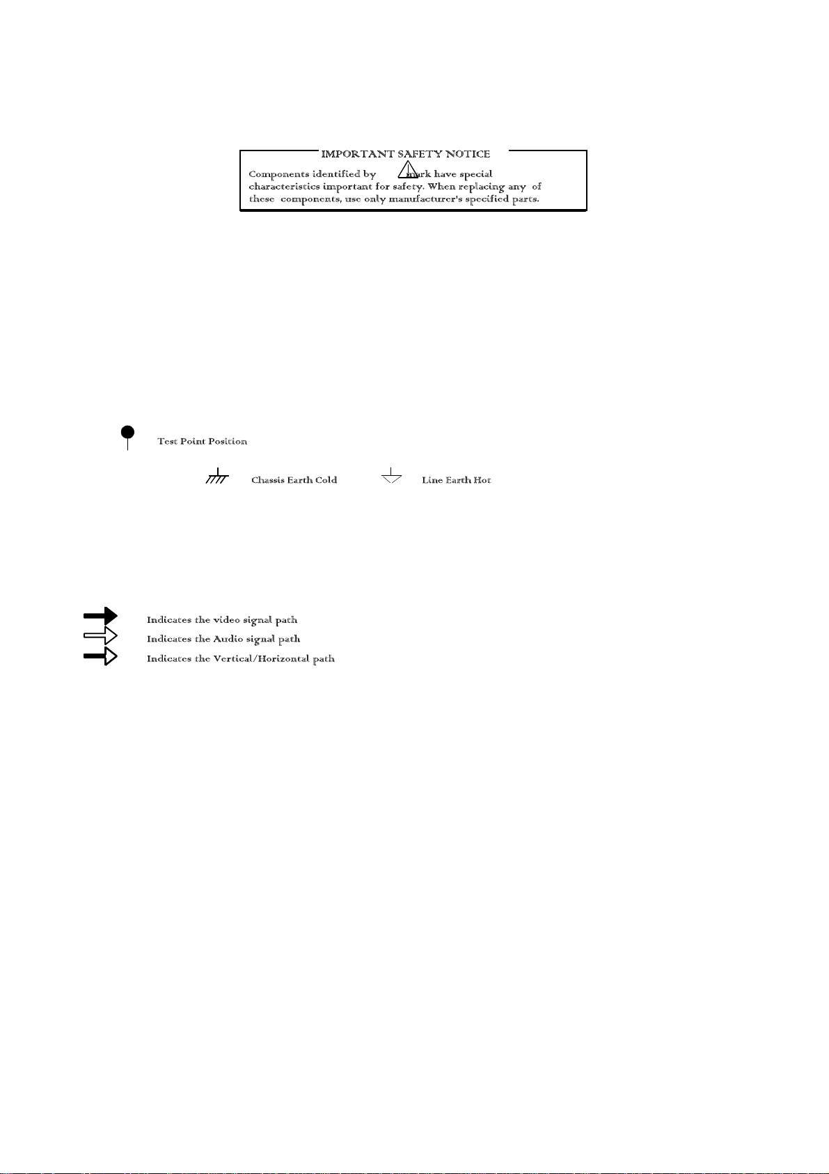
5. TEST POINT
6. EARTH SYMBOL
7. VOLTAGE MEASUREMENT
Voltage is measured by a DC voltmeter.
Measurement conditions are as follows:
Power source AC 220V-240V, 50Hz
Receiving Signal Colour Bar signal (RF)
All customer controls Maximum position
8.
9. This schematic diagram is the latest at the time of printing and is subject to change without notice.
Remarks
1. The Power Circuit contains a circuit area which uses a separate power supply to isolate the earth connection. The circuit is defined by HOT and COLD
indications in the schematic diagram. All circuits, except the Power Circuit, are COLD. Take the following precautions:
Precautions
a. Do not touch the hot part, or the hot and cold parts at the same time, as you are liable to a shock hazard.
b. Do not short-circuit the hot and cold circuits as electrical components may be damaged.
c. Do not connect an instrument, such as an oscilloscope, to the hot and cold circuits simultaneously, as this may cause fuse failure. Connect the earth of the
instruments to the earth connection of the circuit being measured.
d. Make sure to disconnect the power plug before removing the chassis.
23
 Loading...