

Panasonic 9TAWV-TW37003 Installation manual

Install the Common Trigger Box (option: WV-TW37003)
Preface
• If a Common Trigger Box installed in the trunk, for example, and a BWC are connected via
Bluetooth communication, it is possible to activate the BWC controlling from the external
devices or transfer BWC's operating information to the external devices.
• By connecting the Common Trigger Box and Pairing Dock (option: WV-TW37004) using an
Ethernet cable, Bluetooth peer-to-peer wireless communication can be performed.
• If the Common Trigger Box is connected with SA366 (existing model BWC) equipped with
wireless function, it is possible to activate the SA366 automatically controlling from the external
devices or transfer SA366's operating information to the external devices.
WARNING
• To prevent fire or electric shock hazard, do not expose this apparatus to rain or moisture.
Standard accessories
Operating instructions ..............................1 pc.
Warranty card ...........................................1 pc.
Common Trigger Box fixing screws ......... 5 pcs.
(of them, 1 for spare)
Fixing plate ...............................................1 pc.
16
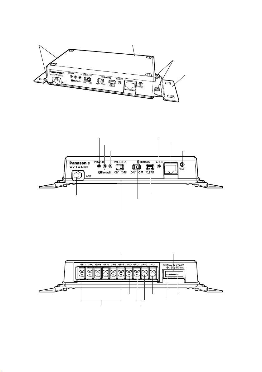
Part names
Common Trigger Box fixing screws (2 pcs.)
(accessory: WV-TW37003)
<Front View>
POWER indicator
ANT terminal
Common Trigger Box
(option: WV-TW37003)
Bluetooth indicator
WIRELESS indicator
Bluetooth
ON/OFF SW
WIRELESS
ON/OFF SW
Common Trigger Box fixing screws (2 pcs.)
(accessory: WV-TW37003)
Fixing plate
(accessory: WV-TW37003)
PAIRED inducator
RJ45 terminal
RESET SW
Bluetooth CLEAR SW
<Rear View>
GP I/O terminal DC IN terminal
GND
GP IN 1 - 6
GND
GP OUT 1 - 2
PIN r
PIN q
17

■ Indicator
POWER indicator Lights up in green when power is supplied to the Common Trigger
Bluetooth indicator Lights up in green when Bluetooth ON/OFF SW sets to ON.
WIRELESS indicator Lights up in green when WIRELESS ON/OFF SW sets to ON.
PAIRED indicator Lights up in green when connecting between Common Trigger Box
■ SW
WIRELESS ON/OFF SW Determines whether to operate the Common Trigger Box via wireless
Bluetooth ON/OFF SW Determines whether to operate the Common Trigger Box via Blue-
Bluetooth CLEAR SW Clear the pairing information between the Common Trigger Box and
RESET SW Restart the Common Trigger Box.
■ Front Terminal
RJ45 terminal Connects with the Pairing Dock using an Ethernet cable, and
ANT terminal Connects an external antenna.
■ Rear Terminal
GP I/O terminal Connects signal lines from the external devices.
DC IN terminal
Box.
Blinking in green(0.5 sec./0.5 sec.) when pairing between the Common Trigger Box and BWC (at least 1 unit) is complete. Up to 10
BWCs can be connected.
Blinking in green(0.5 sec./0.5 sec.) when linking between the Common Trigger Box and SA366 (at least 1 unit) is complete. For SA366
(existing model), up to two units can be linked.
Fast blinking in green (0.25 sec./0.25 sec.) when authentication error
is occurred.
and BWC through the ethernet cable.
LAN mode.
tooth mode.
the BWC.
enables pairing operation.
RJ45 terminal is a dedicated connecting terminal for a Pairing Dock.
It cannot be used for connecting a regular LAN cable.
Input: 6 lines, Output: 2 lines
Input specification:
OFF: Open or 4 V - 5 V DC
ON: Make contact with GND (required drive current: 1 mA or more)
Output specification: Open collector output
ON: 4 V - 5 V DC by internal pull-up
OFF: Output voltage 1 V DC or less
(maximum drive current: 50 mA)
Pin q GND (Black)
Pin w DC IN (Red: Supplies power from the power source of 12 V
DC/24 V DC)
Pin e ACC (White: Detects ACC signal on by car key operation.)
Pin r NC
No-voltage make contact input
(4 V - 5 V DC, internally pulled up)
(maximum applied voltage: 20 V DC)
18
 Loading...