


1.9GHz Wireless Receiver
K-SRC14
1
Rev.1.1

FCC CAUTION
operational failure.
Changes or modifications not expressly approved by the party responsible for compliance could
void the user’s authority to operate the equipment.
This device complies with part 15 of the FCC Rules. Operation is subject to the following two
conditions: (1) This device may not cause harmful interference, and (2) this device must accept
any interference received, including interference that may cause undesired operation.
Note: This equipment has been tested and found to comply with the limits for a Class A digital
device, pursuant to part 15 of the FCC Rules. These limits are designed to provide reasonable
protection against harmful interference when the equipment is operated in a commercial
environment. This equipment generates, uses, and can radiate radio frequency energy and, if not
installed and used in accordance with the instruction manual, may cause harmful interference to
radio communications. Operation of this equipment in a residential area is likely to cause harmful
Compliance with FCC requirement 15.407(c)
Data transmission is always initiated by software, which is the passed down through the MAC,
through the digital and analog baseband, and finally to the RF chip. Several special packets are
initiated by the MAC. These are the only ways the digi tal baseb and por t ion wi ll tur n on the RF
transmitter, which it then turns off at the end of the packet. Therefore, the transmitter will be on
only while one of the aforementioned packets is being transmitted. In other words, this device
automatically discontinue transmission in case of either absence of information to transmit or
Radio Frequency (RF) Exposure Warning
This equipment complies with FCC radiation exposure limits set forth for an uncontrolled
environment and meets the FCC radio frequency (RF) Exposure Guidelines. This equipment
should be installed and operated keeping the radiator at least 20cm or more away from person’s
body (excluding extremities: hands, wrists, feet and ankles).
MEDICAL:
Consult the manufacturer of any personal medical devices, such as pacemakers, to determine if
they are adequately shielded from external RF (radio frequency) energy. The unit operates in the
frequency range of 1.92 GHz to 1.93 GHz.
Do not use the unit in health care facilities if any regulations posted in the area instruct you not to
do so. Hospitals or health care facilities may be using equipment that could be sensitive to
external RF (radio frequency) energy.
2
Rev.1.1
Notice
FCC ID can be found on the bottom of the units.
WARNING:
- The mains plug or an appliance coupler shall remain readily operable.
- To prevent injury, this apparatus m ust be securely attached to the f loor/wall in acc ordance with
the installation instructions.
- The connections should comply with local electrical code.
- The installation shall be carried out in accordance with all applicable installation rules.
- To reduce the risk of fire or electric shock, do not expose this apparatus to rain or moisture.
- T he apparatus should not be exposed to dr ipping or splashing and that n o objects filled with
liquids, such as vases, should be placed on the apparatus.
- All work related to the installati on of this pr oduc t should be m ade b y qua lified s ervice perso nne l
or system installers.
- This product has no power switch. When turning off the power, disconnect the power supply from
the PoE device.
CAUTION:
Before attempting to connect or operate this product, please read the label on the bottom.
The model number and serial number of this product may be found on the surface of the unit.
You should note the model number and serial number of this unit in the space provided and
retain this book as a permanent record of your purchase to aid identification in the event of
theft.
Model No.
Serial No.
3
Rev.1.1

Important safety instructions
1) Read these instructions.
2) Keep these instructions.
3) Heed all warnings.
4) Follow all instructions.
5) Do not use this apparatus near water.
6) Clean only with dry cloth.
7) Do not block any ventilation openings. Install in accordance with the manufacturer's instructions.
8) Do not install near any heat sources such as radiators, heat registers, stoves, or other apparatus (including
amplifiers) that produce heat.
9) Protect the power cord from being walked on or pinched particularly at plugs, convenience receptacles, and
the point where they exit from the apparatus.
10) Only use attachments/accessories specified by the manufacturer.
11) Use only with the cart, stand, tripod, bracket, or table specified by the manufacturer, or sold with the
apparatus. When a cart is used, use caution when moving the cart/apparatus combination to avoid injury
from tip-over.
12) Unplug this apparatus during lightning storms or when unused for long periods of time.
13) Refer all servicing to qualified service personnel. Servicing is required when the apparatus has been
damaged in any way, such as power-supply cord or plug is damaged, liquid has been spilled or objects
have fallen into the apparatus, the apparatus has been exposed to rain or moisture, does not operate
normally, or has been dropped.
14) Make sure that the wall that the shelf will be attached to is strong enough to support the shelf. If not, it is
necessary for the wall to be reinforced.
15) For safety reasons, do not physically modify the product or any optional equipment.
16) To prevent possible fire or electric shock, do not expose this product to rain or moisture.
17) Follow all warnings and instructions marked on this product.
18) To reduce the risk of electric shock, do not disassemble this product. Only qualified personnel should
service this product. Opening or removing covers may expose you to dangerous voltages or other risks.
Incorrect reassembly can cause electric shock.
19) Unplug the AC adaptor from the AC outlet and have the product serviced by qualified service personnel in
the following cases:
A. When the power supply cord or plug is damaged or fra yed.
B. If liquid has been spilled into this product.
4
Rev.1.1

C.
If the product has been exposed to rain or water.
D. If the product does not operate according to this manual. Adjust only the controls that are explained in
this manual. Improper adjustment of other controls may result in damage and may require service by a
qualified technician to restore the product to normal operation.
E.
If the product has been dropped or damaged.
F. If product performance deteriorates.
20) The product should never be placed near or over a radiator or other heat source.
21) Do not use a microwave oven to dry this product.
22) The product may only be installed and serviced by qualified service personnel.
5
Rev.1.1
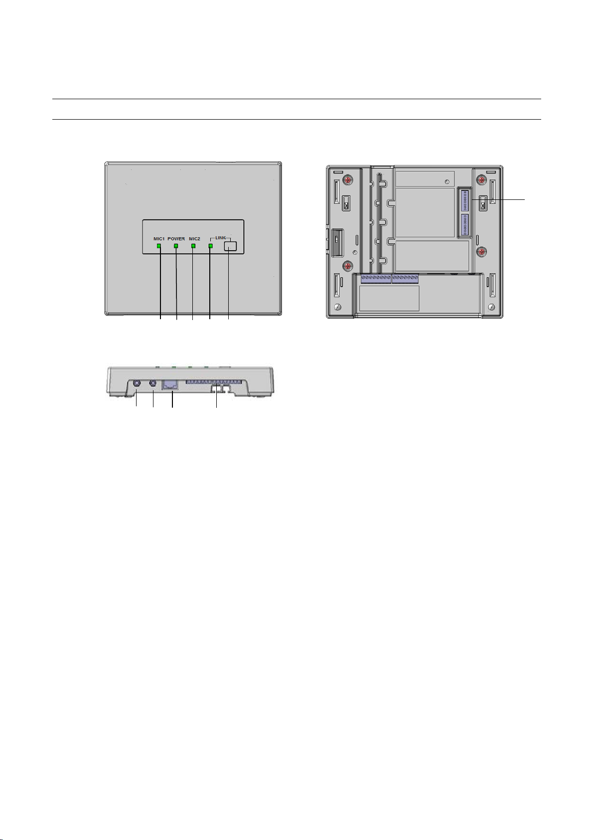
Major operating controls and their functions
3
3 9 8 7 6
5
4 1 2
[1][LINK] button
Pressing this button will becomes register mode with a microphone.
(Linkup connection is established or progress of 20 seconds will cancel this mode.)
Refer to Operating procedures.
[2] POWER indicator [POWER]
(Green/Yellow/Red)
This LED lights green when the power is on and this unit is receivable under normal conditions.
This LED lights as follows to indicate other states:
E2 signal output provided: lighting red (Lighting green at Power OFF)
Page mute signal received: lighting yellow
[3]MIC1/MIC2 indicator [MIC1/MIC2]
This LED lights green when this unit is receiving signals from each microphone under normal conditions.
This LED lights as follows to indicate other states:
E2 signal output provided: lighting red. (Lighting green at E2 ACK input provided)
Page mute signal received: lighting yellow
E1 signal output provided: lighting (300ms) red
Feedback blocker in operation: lighting(5sec) yellow
[4] LINK indicator [LINK]
This LED lights yellow(500ms) when this unit is during ID registration(Pairing)
This LED lights red when this unit is system error
6
Rev.1.1

[5]Control terminals
8-pin and 7-pin Euro blocks are used.
The following terminals are equipped.
E1 CNT: provides E1 signal * output controlled by K-STD14.
E2 CNT: provides E2 signal * output controlled by K-STD14.
* Those are available when K-STD14 is used. Settings of E1 and E2 are performed with K-STD14.
E2 ACK: connects acknowledge signals responding to E2 output.
PAGE MUTE: provides make signal inputs externally when the paging function is used.
RS-232C: is used to control this unit via communication from an external device.
LINK button: provides make signal inputs externally when the external link button is used.
Alert notification button; provides make signal inputs externally when the external Alert notification button is used.
[6] Amplifier interface connector
This connector is used to connect the cable to the amplifier.
A standard CAT5 or CAT5e cable is used to connect to the amplifier.
[7] MIX OUT (unbalanced) connector
This connector provides the audio output of LINE IN of the main unit. Setting the No. 4 of the DIP switch1 to ON allows the audio
outputs of the microphone CH1 and CH2 received by this unit to be provided after mixing with LINE IN. This is an unbalanced
output. A stereo mini plug (φ3.5 mm) is used.
[8] LINE IN connector
This connector is used to provide an audio input from external sources such as a projector or CD. This is a stereo, line level input,
and is internally mixed to a monaural signal. A stereo mini plug (φ3.5 mm) is used.
[9]DIP Switches
Two DIP switches are used.
The settings of this switch are updated at the time of turning on the power.
Settings changed while powered up are not updated until the power is turned off and then back on. (Excluding No.7 of DIP
Switch 1)
7
Rev.1.1
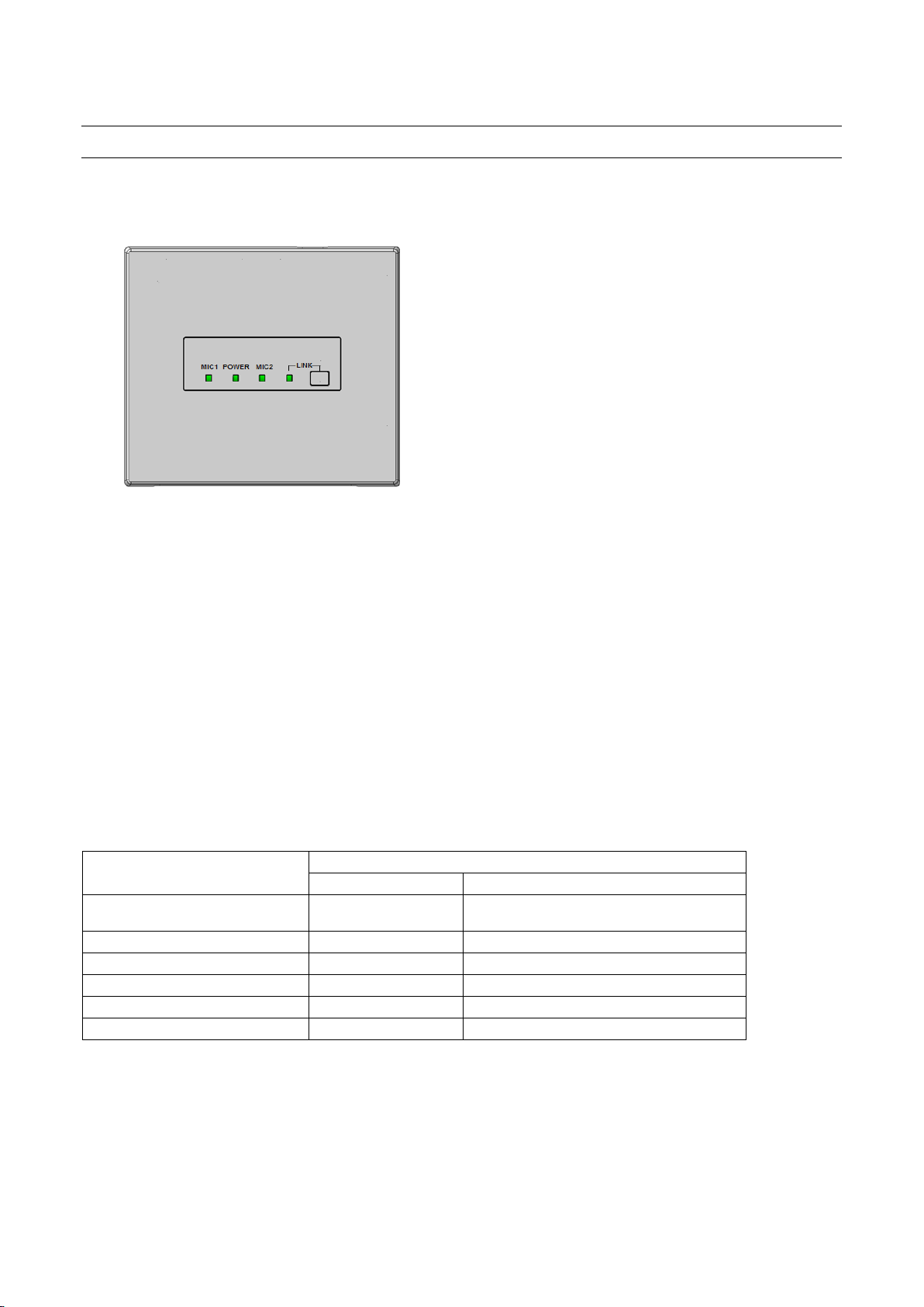
Operating procedures
1. A standard CAT5 or CAT5e cable is used to connect to the amplifier,. After that, turned on amplifier.
2. Power ON of the microphone .
3 .Adjust the volume of external devices such as an amplifier.
4. The LED of the POWER/MIC1/MIC2 indicates the operating state of this unit during operation.
LED
POWER indicator
MIC1/MIC2 indicator
5. The LED of the LINK indicates the operating state of this unit during operation.
The POWER LED of the receiver lights green.
[K-STD14] : Turn on the [PWR/MUTE] button.
[K-SHH14] : Turn on the [PWR LINK] button. And Push [TALK push]button.
The MIC1 or MIC2 LED indicator of the lights green ( depending on a channel to be received.)
The overall volume is adjusted with the external amplifier or the like. Use of the volume button of K-STD14 allows the volume of
itself to be adjusted. In addition, selection of the target with the selection button of K-STD14 allows the volume of the other
microphone received by this unit and the volume of LINE IN of this unit to be adjusted.
E2 signal output provided* Lighting red
E1 signal output provided* Lighting green Lighting red (for 300 ms)
Page mute signal input provided Lighting yellow Lighting yellow
Microphone volume operated* Lighting green No lighting (for 300 ms)
Feedback blocker operated Lighting green Lighting yellow (for 5 s)
Audio link establishment Lighting green Lighting green
* Applicable when K-STD14 is used
Lighting red
(lighting green at E2 ACK input provided)
8
Rev.1.1

Audio link establishment with the DECT AP Lighting Green
During ID registration/pairing Blink yellow at 500ms period
System error Lighting Red
9
Rev.1.1
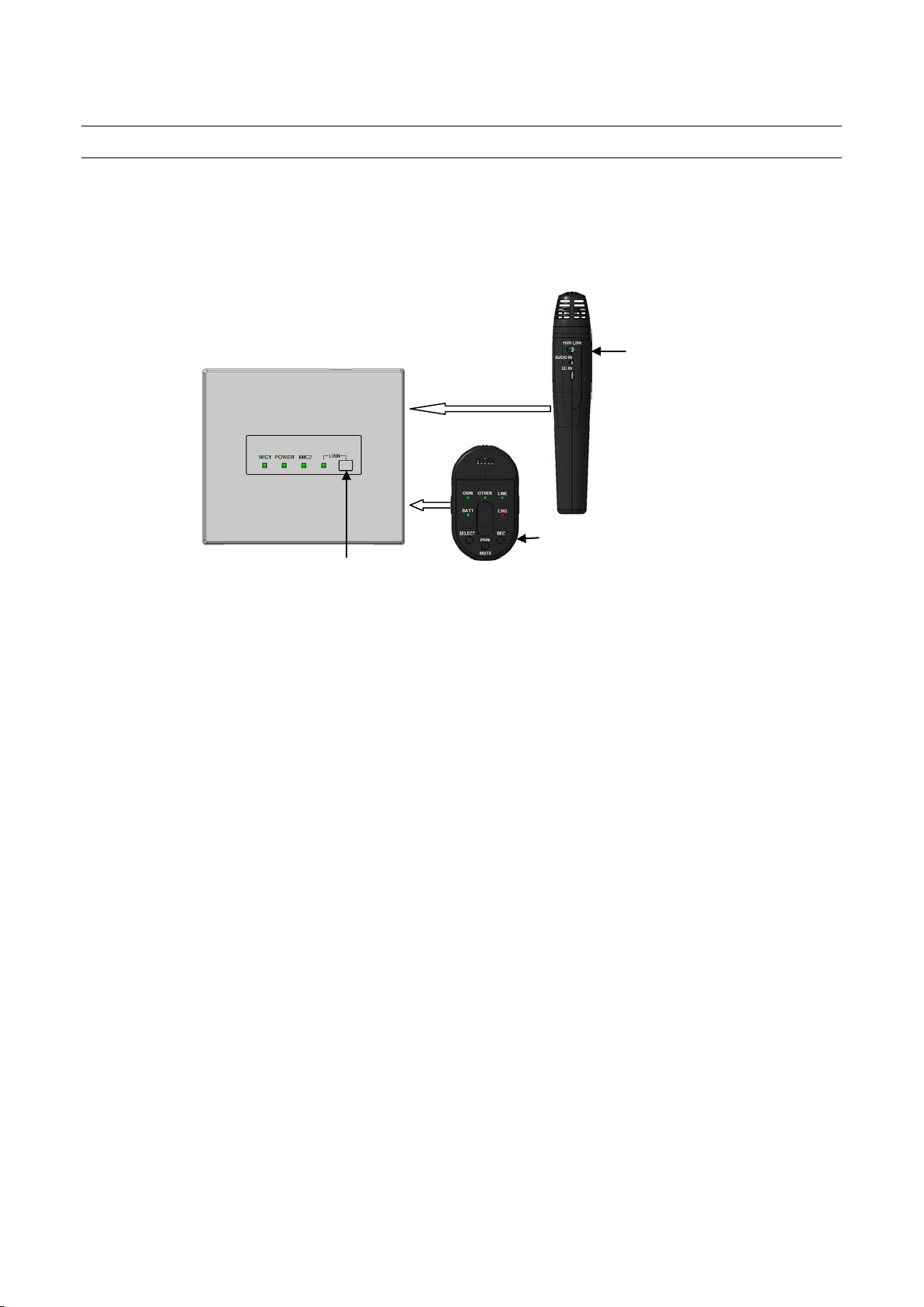
Connection registration of the microphone to a receiver
1.
When connecting it with the receiver which has not connected once, pairing registration is needed first.
Please perform pairing registration according to the following procedure.
(Only the alert operates without registration work.)
1. Press a receiver's [LINK] button, and a receiver is made into register mode
.
2. (a) Pendant microphone:
Press [PWR/MUTE] button and [REC] button will register for receiver.
Pendant microphone [BATT] indicator is green light.
(b)Handheld microphone:
Microphone LINK switch (inside the battery cover) is ON. (Different receiver connection)
(Please read the operating instructions of the Handheld Microphone (K-SHH14).)
Press [PWR LINK] button will register for receiver.
Handheld microphone [BATT] indicator is blinking ( green ).
A pairing setup is required first.
[PWR LINK] button
[PWR/MUTE] button
[LINK] button
10
Rev.1.1

Classroom Audio
Pendant Microphone [K-STD14]
Handheld Microphone [K-SHH14]
1. Press [PWR/MUTE] button will start a microphone.
A microphone can be used in a classroom. (MIC1 or MIC2 LED indicator lighting green)
Note:
• Also read the operating instructions of the Pendant Microphone (K-STD14).
1. Press [PWR LINK] button will start a microphone.
2. Press [TALK push] button will start a microphone.
A microphone can be used in a classroom. (MIC2 or MIC1 LED indicator lighting green)
Note:
• Also read the operating instructions of the Handheld Microphone (K-SHH14).
11
Rev.1.1
 Loading...