

Page 1

GAS-POWERED CUTOFF SAW
Item# 999000
OWNER’S MANUAL
Read carefully and understand RULES FOR SAFE OPERATION and instructions before
operating. Failure to follow the safety rules and other basic safety precautions may
result in serious personal injury.
Page 2

Introduction
Thank you for choosing a Northern Tool + Equipment product, the Cutoff Saw, Item# 999000.
For future reference, please complete the owner’s record below:
Model:____________________________ Purchase Date:_______________________
Save the receipt, warranty and this Owner’s Manual. It is important that you read the entire
manual to become familiar with this product before using it
This Manual contains operating and safety instructions for your cutoff saw. For maximum
performance and satisfaction from your cutoff saw, it is important that you read and
understand the maintenance and safety manual before operating the saw. Northern Tool +
Equipment strongly recommends that this machine not be modified and/or used for any
application other than that for which it was designed. If you have any questions or do not
understand any of the instructions in this Manual, please call 1-800-222-5381.
Because the cutoff saw operates at high speeds, special safety precautions must be observed
before operating the saw. Careless or improper use could cause serious or even fatal injury.
The engine for the cutoff saw has been approved and certified by U.S. EPA
1
.
Page 3

Table of Contents
Main parts and their functions 3–5
Safety precautions 5–8
Specifications 9
Operation guide to the cutoff saw 10–13
1. Before starting 10–11
2. Starting 11–12
3. Operation 12
4. Emergency Stopping 12
5. Notes on operation 12–13
Adjustment of cutoff saw 13
1. Adjusting V-belt tension 13
2. Adjusting carburetor 13
3. Adjusting blade guard 13
Maintenance & repair of cutoff saw 13–15
1. Cleaning and maintenance of air filter 13–14
2. Maintenance of spark plug 14
3. Replacing starter rope 14–15
4. Replacing pawl 15
5. Maintenance chart 16
Storing cutoff saw 17
Exploded parts views and parts lists 18–25
1. Crankshaft Housing Assembly 18
2. Crankshaft & Piston Assembly 19
3. Cylinder & Muffler Assembly 20
4. Oil Tank & Carburetor 21
5. Handle & Main Cover Assembly 22
6. Air Filter Assembly 23
7. Cutter Assembly 24
8. Transmission Box & Assembly 25
2
Page 4
Main parts of the cutoff saw and their functions
This product is composed of two main sections: a gasoline-powered 2-stroke engine and a
driving/cutting system. When engine speed is up to 3800 RPM, the cutting blade, driven by the
engine via a belt transmission system, begins to rotate at a high speed and is ready for cutting
work.
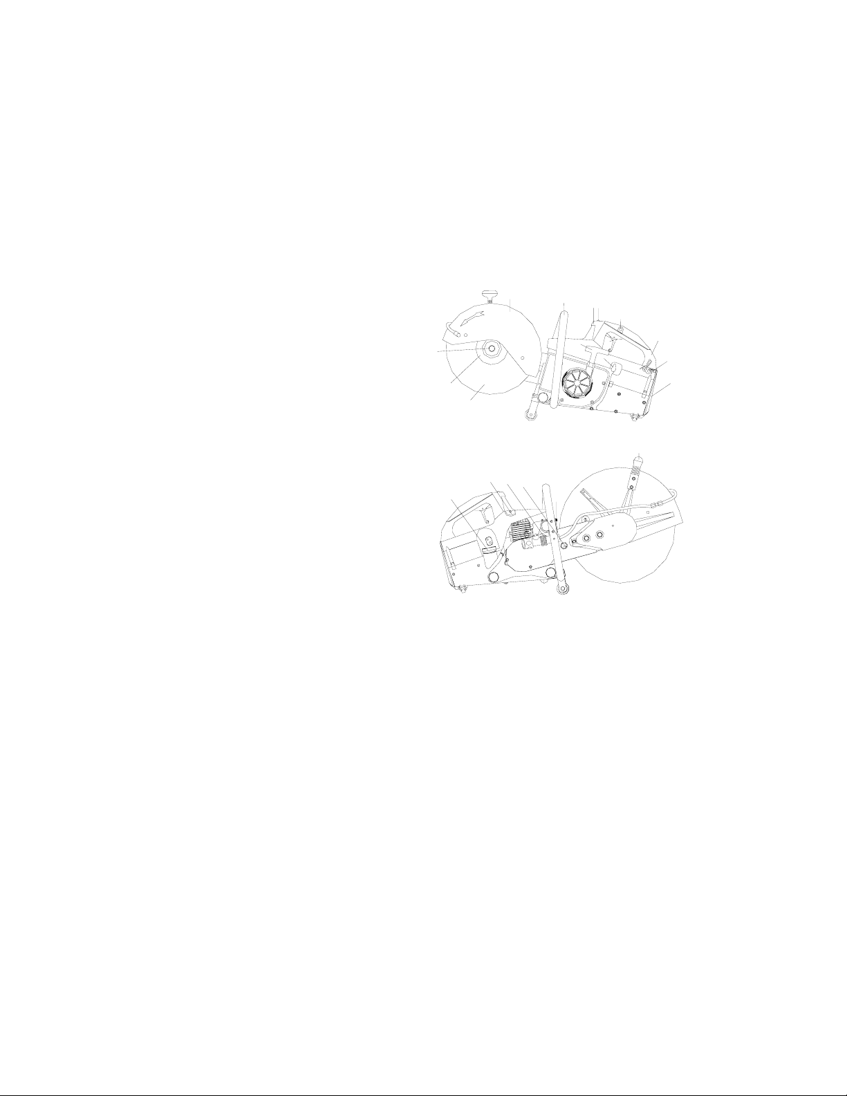
Shown below are the main parts of the cut-off saw and their corresponding function descriptions
(Ref. Fig. 1):
1. Blade
2. Flanges
3. Hexagon Bolt
4. Blade Guard
5. Front Handle
6. Spark Plug Cover
7. Kill Switch
8. Full Throttle Lock Button
3
2
1
4
5
6
7
8
9
14
13
10
11
12
9. Throttle Trigger
10. Rear Handle
20
11. Filter Cover Lock Lever
16
12. Air Filter
13. Choke Lever
15
17
18
19
14. Starter Grip
15. Fuel Tank Cap
16. Decompression Valve
17. Water Attachment
18. Tensioning Nut
19. Muffler
20. Adjusting Lever of Blade Guard
Fig. 1
1. Blade
Diamond or abrasive blades. Depending on the material to be cut, these blades are made of
different materials. Be sure to choose right blade for the material being cut. The maximum
diameter of the blade for the saw is 14". The operating speed of the blade should be above or
equal to 5300 RPM.
2. Flanges
Clamp and support the diamond or abrasive blade.
3. Hexagon Bolt
Tightens blade flange.
4. Blade Guard
Safety guard directs sparks and dust away from operator.
3
Page 5

5. Front Handle
Used to securely hold the saw while under operation.
6. Spark Plug Cover
A removable cover for access to the spark plug.
7. Kill Switch
Engine stops when this switch is pressed and held.
8. Full Throttle Lock Button
Locks the throttle in full open position by pressing this button while the trigger is fully depressed.
Pressing and releasing the trigger returns the throttle to idle position.
9. Throttle Trigger
Controls engine speed by manipulating the throttle. Pulling the trigger backward opens the
throttle and the engine accelerates. Releasing the trigger slows down the engine.
10. Rear Handle
Used to securely hold the saw while under operation.
11. Filter Cover Lock lever
Locks the air filter cover. Pull back on the lever to open the filter cover.
12. Air Filter
Filters dirt and debris from entering carburetor.
13. Choke Lever
Turning this lever counter clockwise closes the carburetor. Used to prime engine (cold starting).
Turn clockwise for normal operation.
14. Starter Grip
Pull to start engine.
15. Fuel Tank Cap
Open this cap for filling the fuel. Close the tank for starting and operation.
16. Decompression Valve
Press down on this valve to make starting easier. When air pressure in the engine reaches a preset
value, it automatically closes.
17. Water Attachment
Feeds water to both sides of diamond blade. Connect to water supply for wet cutting.
18. Tensioning Nut
For V-belt tension adjustment. Turn this nut clockwise to loosen the V-belt, turn the nut
counterclockwise to tension the V-belt.
19. Muffler
Reduces both noise and emissions.
4
Page 6

20. Blade Guard Adjusting Lever
Allows adjustment of blade guard to direct dust away from operator.
SAFETY PRECAUTIONS:
As the cutoff saw is a high speed power tool, improper use of this saw might be
hazardous. To avoid property damage or personal injury, it is EXTREMELY
IMPORTANT to read, fully understand and observe the following safety
precautions before operating this cutoff saw.
1. Worksite Requirements:
The worksite should be free of any materials or objects that are flammable or
explosive.
Surroundings should be in order, without clutter, have sufficient visibility and be
well ventilated. The flooring the operator stands on should be nonskid. Take extreme care when
working in wet and freezing weather (rain, snow, frost, ice).
Bystanders should keep away from the saw when it is operating. Children, the handicapped and
animals should never be allowed in the work area.
Loose objects may be thrown toward the operator by the cutting tool; position the object to be cut
securely to ensure it can’t be moved by the blade when cutting.
2. Blade:
Before installing a blade, make sure that the maximum operating speed of the blade
is above or equal to the spindle speed of your cutoff saw. Inspect the cutting blade
frequently and replace immediately if the cutting blade is cracked or warped.
Cracked or warped blades may shatter or break and cause serious personal injury.
Failure to follow these directions may cause the blade to shatter or crack in use,
causing serious or fatal injury.
Never use carbide-tipped, woodcutting or circular machine blades. They can cause severe
personal injury from reactive forces, blade contact or thrown objects.
Use of the wrong cutting blade for which it was not designed may cause that blade to shatter,
causing serious or fatal injury. Only use the cutting blade approved for the type of material to be
cut.
Diamond blades have a much better cutting performance than standard abrasive blades. The
blades are steel centered and diamond particles are imbedded in their cutting edges.
Wet or dry cutting is possible. Cutting wet will extend the life of your diamond blades. A water
attachment comes as standard equipment with this cutoff saw. Before using the water attachment,
make sure that the screw that secures the outlet tube is tightened.
5
Page 7

Always install the blade so that the arrow on the blade points in direction of the rotation of the
spindle.
Before carrying or transporting your cutoff saw, make sure the engine is OFF. Never leave the
engine running while unattended (e.g. on the ground).
Proper tension of the V-belt is important. In order to avoid a false setting, the tensioning
procedure must be followed as described in your manual. Always make sure the hexagonal collar
nuts for the cast arm are tightened securely. Check V-belt tension after one hour of operation and
correct if necessary.
3. Operator:
The cutoff saw is a one-person tool. Start and operate this saw without assistance.
Make sure you are in good physical condition and are not under the influence of any substance
such as drugs or alcohol which may impair vision or dexterity. Take breaks as needed to prevent
you from getting fatigued.
Never let the cutoff saw run unattended. NO untrained personal should ever be allowed to use a
cutoff machine. Bystanders, especially children and animals, should not be allowed in the area
where a cutoff machine is in use.
Do not lend or rent your cutoff machine without this Operation Manual. Employers should
establish a training program for operators of this saw to ensure safe operation of this powerful
tool.
Avoid loose-fitting jackets, scarves, neckties, jewelry, flared or cuffed pants, unconfined long
hair or anything that could become caught or entangled on any moving parts of the unit. Wear
overalls or long pants to protect your legs. Do not wear shorts.
Protect your hands with gloves when handing the cutoff saw. Heavy-duty, nonslip gloves
improve your grip and protect your hands.
Operate the cutoff saw with both hands, keeping a firm grip on the front and rear handles.
Maintain good balance and footing at all times.
Good footing is most important. Wear sturdy boots with nonskid soles. Steel-toed safety boots are
recommended.
To reduce the risk of injury to your eyes, never operate the cutoff saw unless
wearing goggles or properly fitted safety glasses with adequate top and side
protection.
Proper eye protection is a must!
Wear an approved safety hard hat to protect your head. Cutoff machine noise could
damage your hearing: Wear earplugs or ear protectors at all times.
Cutting masonry, concrete, metal and other materials can generate dust, mists and
fumes containing chemicals known to cause serious or fatal injury or illness, such as
respiratory disease, cancer, birth defects or other reproductive harm.
6
Page 8

Cutting masonry, concrete and other materials with silica in their composition may give off dust
containing crystalline silica. Silica is a basic component of sand, quartz, brick clay, granite and
numerous other minerals and rocks. Use of an approved respirator is recommended.
Do not cut materials containing asbestos, as asbestos dust can cause severe physical injury. Do
not cut materials containing highly volatile or flammable substances.
4. Inspection of the cutoff saw before use:
1. Make sure there are no loose objects on or near the saw.
2. Except for the carburetor adjustment screws, all other bolts, nuts, screws and the fuel tank cap
should be securely tightened. Make sure all rubber hoses for oil flow are tightly connected with
no leaks.
3. Make sure the blade rotates smoothly; the starter rope can be pulled through and guided back
without being tangled.
4. Check to make sure the Throttle Trigger, the Full Throttle Lock Button, the Choke Lever, the
Decompression Valve and the Kill Switch all function well without failure.
5. Check to make sure the blade guard has no visual damage. Adjust the guard as necessary so the
spark beam generated during cutting can be directed
away from the operator (Ref. Fig. 2).
6. Check to make sure the V-belt is properly tensioned.
7. Make sure the saw is free of oil spillage.
8. Make sure the main cover and the handles are dry
and clean.
9. Do not attempt to start the saw if damage is found or
if it’s not completely and securely assembled and
properly adjusted.
Fig. 2
5. Precautions on starting:
1. Keep a good balance and secure footing.
2. Take hold of the starter grip firmly; do not wrap the rope
around your hand.
3. To start, place the machine firmly against the ground and
make sure the blade is not in contact with the ground or the
object to be cut.
4. Pull sharply on the rope and guide it back slowly. Do not
let go of the grip halfway through
the pull to prevent it from snapping back.
Fig. 3
6. Precautions on operation:
1. Keep a good balance and secure footing while holding the saw firmly at all times.
(Ref. Fig. 3)
2. Press the throttle trigger backward slowly to make the engine accelerate gradually. Wait until
the blade builds up the RPMs before beginning to work.
3. Move the rotating blade slowly toward the object to be cut, increase the pressure gradually
after the cutting edge comes in contact with the object. Make sure the cutting depth is appropriate.
4. Do not change direction of the cut or twist during the cut as this may produce a high
7
Page 9

torsion load on the blade and may cause it to break or shatter. Only move the machine along a
straight line, forward or “to and fro” in the cutting direction.
5. When cutting, position the saw at an appropriate distance so that your body is clear of the blade
attachment yet you don’t have to overreach.
6. Release the pressure on the saw when the blade completes a cut. The cutoff portion of the
object may drop, so make sure it won’t hit any part of your body or pinch the blade.
7. Whenever you hear an abnormal sound coming out of the cutoff saw, stop cutting immediately
for inspection (Note the muffler and the blade are very hot at this time, so take care not to get
burned). Only resume work after the trouble is eliminated.
8. Do not make adjustments or perform any maintenance or troubleshooting with the cutoff saw
while it is running.
9. Take precaution when re-entering a cut and do not turn the blade at an angle or push it into the
cut, as this may cause the blade to become pinched.
7. Precautions on fueling:
1. Fuel the machine only in a well-ventilated environment.
2. Before refueling, let the engine cool off naturally. Do not take
any other forceful measures to cool the engine down.
3. Remove the fuel tank cap slowly and carefully to allow any
pressure build-up in the tank to be released (Ref. Fig. 4).
4. Tighten fuel cap securely after fueling and clean off spillage,
if any.
8. Notes on transporting:
1. Always stop the engine before relocating the saw.
2. When carrying the machine with a hot engine, take care not to
have any part of your body come in contact with the muffler;
burns could occur.
3. Prevent the saw from touching the ground or any hard objects.
9. Notes on maintenance:
Perform any maintenance or repair work in clean and neat environment. Use proper tools and
operate with caution.
Do not attempt to modify your cutoff saw in any way. Use only identical spare parts for
replacement.
The cutoff saw is only intended for cutting work and cannot be used for prying or shoveling
away any objects, or used as a grinding tool with the sides of the blade.
8
Fig. 4
Page 10

Specifications:
Engine
Engine
Model 1E49F (Engine Family 3ZHIS.0642CR)
Type Single-cylinder, two-stroke, air-cooled
Cylinder bore 1.96"
Piston stroke 1.36"
Displacement 64.1 cc
Max. output 3.8 HP
Speed at max. output 8500 RPM
Max. torque 3.5N.m
Idle speed 2400 RPM
Lock-up speed of clutch 3800 RPM
Min. fuel consumption 544 g/(kw.h)
Fuel mix
Fuel tank capacity 0.4 gallons (1.5L)
Ignition type
Electrode gap of spark plug 0.02"
Spark plug thread M14 x 1.25; 0.38" long
Gasoline Minimum octane rating 93
Oil Two stroke engine oil
Mix ratio 75:1
Electronically controlled (breakerless) magneto
ignition
Blade
Starting method Recoil start
Rotation direction Clockwise
Diameter Maximum 14"
Max. operating speed 5300 RPM
Thickness 0.1"–0.24"
Arbor hole diameter 1"
Types Composite abrasive blade or diamond abrasive
blade
Cutting depth (with thrust plate dia.
4 1/2")
Sound level 110dB
Overall dimensions (29.5" x 14" x 12")
Max. 4 1/2"
9
Page 11

Operation Guide to Cutoff Saw
1. Before starting:
Preparation includes clearing and arranging work surroundings, wearing proper clothing and
protection, and inspecting the cutoff saw. In preparation, please follow the procedures described
in the appropriate section of this manual. For additional preparation work before starting, please
follow instructions given below:
Fueling:
a) Before starting, check if there is any fuel left in the fuel tank.
b) This engine is engineered to operate on mixture of unleaded gasoline and quality two-stroke
engine oil. Octane rating of the gasoline should at least be 93.
c) Gas-to-oil mix ratio is 75:1.
d) When mixing fuel, pour engine oil into the canister first, and then add gasoline (make sure the
mix ratio is 75:1). Shake the mixture in the canister thoroughly.
e) Clean the fuel tank cap and the area around it as necessary to ensure no dirt
falls into the tank. Finally pour the fuel mixture into the tank and tighten fuel tank cap securely.
f) Only mix sufficient fuel for a few days work, the maximum storage time of mixed fuel is 3
months.
Choosing the right blade:
a) Blade diameter can be 12" or 14". Choose an appropriate size and type of blade which best
suits the cutting work. Keep in mind the blade size needs to be fitted with the blade guard. The
diameter of the arbor hole for the blade should be 1". Blade thickness should be within the range
of .100"–.240".
b) Blade types:
For your reference, choose composite abrasive blades for cutting of asphalt, concrete, stone, brick,
steel and plastics. Choose diamond abrasive blades for cutting of asphalt, concrete, stone, hard
rock, brick, etc.
Note: There is a rotation direction indicator marked on each diamond blade. When mounting,
make sure it corresponds to the rotation direction of the arbor. If you are not sure which blades
are proper for your cutting jobs, contact your dealer or distributor for information.
c) Fitting/Replacing the blade: (Ref. Fig.5)
Slide the locking pin (1) through the bore in the Vbelt guard (2) (turn the blade until the locking pin
engages in one of the bores on the belt pulley (3).
Use the combination wrench to loosen and unscrew
the hexagon bolt (4).
Remove the metal washer (5), the flange (6) from
the arbor together with the blade to be replaced.
Mount the new blade (7).
Fit the flange and metal washer.
Screw in the hexagon bolt and tighten it with the combination wrench.
Finally draw the locking pin out of the V-belt guard.
10
Fig. 5
Page 12

Tensioning the V-belt: (Ref. Fig.6):
Loosen and unscrew the two hexagon bolts (2) on the V-belt guard (1) and then remove the Vbelt guard.
Loosen the three hexagon bolts (4) on the bearing plate (3).
Turn the tensioning nut (5) clockwise until the V-belt is tensioned.
Tighten the three hexagon bolts on the bearing plate.
Fit the V-belt guard and fit and tighten the two hexagon bolts (2).
2. Starting (Ref. Fig.7):
Place the cutoff saw on the ground and make sure it’s well balanced; see to it that the saw blade
does not touch any objects or the ground and that there is no person within the swivel range of the
saw.
Press the button of the decompression valve (1).
Set the choke lever (2) to an appropriate position:
to
if the engine is cold;
to
if the engine is warm (even if the engine has already run but is still cold);
if the engine is warm (latched position for warm start).
to
Pull the throttle trigger (3) backward as far as the stop and hold it in position.
Press down the full throttle lock button (4).
Release the throttle trigger (3).
Fig. 6
Fig. 7
11
Page 13

Hold the front handle with left hand and firmly press the cutoff saw against ground, place the
right foot on the carburetor box cover.
Holding the starter grip (5) securely, slowly pull out the starter rope for a short distance, and then
pull it through quickly and strongly.
Note: Starter rope is 3 3/4-ft. long; do not pull the rope out more than its length otherwise it may
break or cause damage to the starting system.
• Do not let go of the starter grip.
• After pulling, guide the rope back into place slowly.
• Pull the rope only straight up and down through the rope guide bushing to prevent it
from wearing.
After the rope has been pulled through:
• If the engine does not start, press the button of the decompression valve again and
restart the engine.
• If the engine runs for a while but doesn’t keep running, press the decompression valve
in, move the choke lever to
As soon as the engine is running, briefly blip the throttle trigger (3) at once. The full throttle lock
button (4) reverts to its original position and the engine idles.
If the engine is new, or has been stored for a long period of time, pull the starter rope through
several times to ensure that sufficient fuel is delivered into the fuel line and combustion chamber
of the engine.
3. Operation:
The blade will not run when the engine idles.
When the cutoff saw is ready for actual cutting work, gently pull the throttle trigger (3) backward
to accelerate the engine, when the speed is over 3800 RPM, the blade begins to rotate and speeds
up. When the blade speed is up and stable, you can begin to move the saw slowly toward the
object to be cut. After the cutting edge comes in contact with the object, increase pressure to the
saw slowly until the blade is at the desired depth. Finally hold the machine securely and move
along a straight line to complete the cut.
To stop or halt the cut (when a cut is completed, or the engine runs out of fuel halfway, or
abnormal sound is heard), first lift the blade out of the cut, then release the throttle trigger, wait
until the engine slows down to idle speed and the blade stops running, then finally turn off the
machine.
4. Emergency stopping (Ref. Fig.8):
Under normal conditions, the machine is to be turned off when
the engine idles. However, if a malfunction or emergency
occurs during cutting, you can stop the engine immediately by
pressing and holding the Kill Switch (2) on the front end of the
rear handle (1). But note that the service life of some
components of the saw may be adversely affected if the engine
is stopped too often during cutting.
5. Notes on operation
Follow all applicable instructions in this manual when operating the cutoff saw.
During the break-in phase, which takes about 8 hours, the saw must not be operated at high
speeds without load (do not pull the throttle trigger beyond 3/4 of full throttle). Following this
procedure will lengthen the service life of your machine.
and then restart the engine.
12
Fig. 8
Page 14

After the saw works for a certain period of time, let the engine idle on for a while to dissipate the
heat. This will prevent some engine parts (ignition system, carburetor, etc.) from being damaged
by over heating.
ADJUSTMENT OF CUTOFF SAW
1. Adjusting V-belt tension:
Refer to the instruction described above in the section titled “Tensioning the V-belt.”
2. Adjusting carburetor:
The carburetor has been preset and adjusted at the factory to reach the optimum fuel-air mixture
for a smooth, fuel efficient, reliable running engine with low emissions. The air
filter and the spark plug need to be checked and maintained regularly. However, if the cutoff saw
is found to be unsatisfactory in operation (such as the idle speed either too high or too low, or
abnormal exhaust emission still persist), a slight adjustment on the carburetor might be necessary,
which includes (Ref. Fig. 9):
Standard setting adjustment:
Find the Low Speed Adjusting Screw “L” (see Fig.9, inside
the upper hole of the carburetor seal cover), use a screw
driver to turn the screw L clockwise all the way to its end.
Then turn the screw L backwards (counterclockwise) 360°.
Adjusting idling speed:
It is usually necessary to adjust the idle speed after Standard
setting adjustment (above). To adjust idle speed, start the
engine first.
If the idle speed is too low, the engine may shut off after
starting. In this case, make the standard setting first as
instructed [above], then turn the idle speed adjusting screw LA
(see Fig. 9) inside the lower hole of carburetor seal cover
clockwise until the blade starts to run. Then turn the screw LA
backwards (counterclockwise)
1/4 circle (90°).
If the idling speed is too high, the blade will run at idling speed, which is not good for the cutoff
saw. In this case, make standard setting adjustment first, then turn the idling speed adjusting
screw LA counterclockwise until the blade stops running. Then turn the screw
LA 90°further (counterclockwise).
3. Adjusting blade guard (Ref. Fig.10):
The blade guard deflects sparks from the operator. Move the a
lever (2) to change the position of the blade guard.
MAINTENANCE & REPAIR OF THE CUTOFF SAW
1. Cleaning and maintenance of the air filter
Dust and foreign build-up accumulated on the air filter may affect
engine performance, increase fuel consumption and cause difficulty i
starting; therefore, it is important to perform regular maintenance. The
frequency of this depends on the conditions of the cutting jobs as well as
material being cut both wet or dry. For dry cutting, maintenance is required every 48 hours. For
instructions, see Fig. 11.
13
djusting
n
Fig. 9
Fig. 10
Page 15

1. Set the choke lever to
2. Pull the filter cover lock lever (7) backward to let the
filter cover (1) swing open. Then take out in succession p
filter (2), pre-filter (3), filter housing (4), paper air filter (5),
and the secondary filter (6). Then clean and dry all these
parts. Replace if any are damaged. Finally replace all of
them in succession and close the filter cover.
2. Maintenance of spark plug (Ref. Fig. 12):
Wrong fuel mixture (too much engine oil in the gasoline),
low quality gasoline or oil, dirty air filter, clogged spark
arrestor screen, and other unfavorable running conditions
are factors
affecting the condition of the spark plug as they cause
carbon
deposit accumulation, which results in trouble in engine
operation. Therefore, if the engine is down on power,
difficult to start or runs poorly at idling speed, first check
the spark plug.
1. Remove the spark plug cover (2) on the front end of the
main cover (1).
2. Remove the plug boot (3) and the spark plug (4) in
succession.
3. Clean off the carbon build-up on the spark plug.
4. Check electrode gap A to see if it is 0.020": readjust if necessary.
5. Replace spark plug after approx. 100 operating hours, or earlier if the electrodes are badly
eroded. (A BPMR7R-type spark plug is recommended for replacement.)
6. Refit the plug boot and make sure it is snugly connected to the spark plug.
3. Replacing starter rope (Ref. Fig. 13):
The starter rope may need to be replaced when frayed or broken.
1. Unscrew the screws (2) on the flywheel/starter cover (1) and remove the cover from the engine
unit.
2. Remove the spring clip (8), remove the rope rotor (7) with pawl (9).
3. Using a screwdriver, unscrew the screw plug (3) on top of the starter grip, remove the starter
rope (4) out of the grip.
4. Put a new rope down through the grip and the rope guide bushing (5), make a simple knot at
the end of the rope and screw in the screw plug (3)
5. Thread the rope through the rope rotor (7) (enter from the hole on the rotor groove) and secure
it with a simple knot.
6. Wind the rope around the rope rotor (7) clockwise until there is a length of about 12" left
unwound.
7. Slip the rope rotor onto the starter post (6) and turn it back and forth a little until the anchor
loop of the rewind spring engages.
8. Replace the pawl (9) in the rope rotor.
9. Press the spring clip (8) onto the starter post and over the peg of the pawl with a screwdriver.
Note: The spring clip must point counterclockwise.
.
re-
Fig. 11
Fig. 12
14
Page 16

10. To tension the rewind spring, first guide the rope through the notch on the edge of the rope
rotor and form a loop, use it to turn the rope rotor 4–5 times counterclockwise.
11. Then hold the rope rotor tight, pull out the twisted rope and untangle it.
12. Release the rope rotor, slowly let go of the starter rope so that it is wound up on the rope rotor.
13. Refit the flywheel/starter cover (1) and screw in the four screws (2).
4. Replacing pawl (Ref. Fig. 13):
The pawl functions as a link between the rope rotor and the c
(by engaging and disengaging the starter cup) and needs to be
replaced if damaged.
1. Unscrew the screws (2) on the flywheel/starter cover (1) and
remove the cover from the engine unit.
2. Remove the spring clip (8), then remove the damaged
pawl (9).
3. Install a new pawl.
4. Refit the spring clip (8) and the flywheel/starter cover (1) in
succession.
rankshaft
Fig. 13
15
Page 17

5. Maintenance chart
The following information refers to normal operating conditions. The specified intervals must be
reduced accordingly when working under aggravated conditions (severe dust formation, for
example) and with longer daily working hours.
Before
starting work
After work or daily
Every time
after refueling
Weekly
Monthly
In the event of
a malfunction
If damaged
As required
Visual
Machine
Throttle trigger, Kill
Switch
Fuel tank Clean √
(all filter
components)
Cylinder fins Clean √
screen
in the muffler
Spark plug Adjust
Nuts and bolts (but
not adjusting
screws)
Rubber buffer Replace √
Support/Bracket Clean √
inspection
Clean √
Functional test √ √
Check √ Filter in fuel tank
Replace √
Clean √ V-belt
Replace √ √
Clean √ √ √ Air filter
Replace √ √
Inspect √ Spark arresting
Clean or
replace
Check idle
speed (the
cutting wheel
must not run)
Adjust idle
speed
electrode gap
Retighten √ √ √
Check and
clean
Replace √ √
√ √ Complete
√
√ √ Carburetor
√
√ √
√ √ √ Blade
16
Page 18

Storing Cutoff Saw
For long periods of storage:
1. Drain and clean the fuel tank, run engine until carburetor is dry.
2. Thoroughly clean the cutoff saw; tighten all nuts and bolts (except for adjusting screws).
3. Remove the blade and loosen the V-belt.
Notes on transport and storage:
1. Avoid knocks and bumps.
2. Abrasive blades must not be exposed to direct sunlight or other sources of heat during transport
and storage.
Store the machine in a place free of moisture and heat source, preferably in a place with
consistent temperature. Do not store it near corrosive liquids.
3. Composite blade must be protected against frost.
The remainder of this manual provides detailed exploded parts views
and parts lists for the cutoff saw.
17
Page 19

1. Crankshaft Housing Assembly
Item Ref Description Qty
1 1E49F01011 Screw M5×20 10
2 1E49F01010 Plug 1
3 1E49F01006 Cover 1
4 1E49F01011 Screw M5×20 3
5 GB97.1 Washer 5 3
6 1E49F05000 Coil 1
7 B1FUD1 Oil seal 17×28×7 1
8 1E49F01001 Crankshaft housing-Left 1
9 GB/T276-94 Ball bearing 6203 1
10 1E49F01003 Gasket 1
11 1E49F01004 Positioning Sleeve 2
12 1E49F01002 Crankshaft housing-Right 1
13 B455 Oil seal 15×24×7 1
14 1E49F01008 Oil needle 1
15 GB/T276-94 Ball bearing 6202 1
16 1E49F01005 Cover 1
17 1E49F01007 Plug 1
18
Page 20

2. Crankshaft & Piston Assembly
Item Ref Description Qty Item Ref Description Qty
1
2
3
4
5
6
7
8
9
10
11
12
13
14
15
1E49F01009A
1E49F03006-
1E49F03006 Starter grip 1
1E49F03006-
1E49F03011 Rewind Spring 1
1E49F03005 Spring Cover 1
1E49F03004A Rope rotor 1
1E49F03009A Pawl 1
1E49F03008 Spring clip 1
1E49F02001 Collar nut 1
1E49F02010A Starter cup 1
1E49F02002A Flywheel 1
1E49F02000A Crankshaft 1
1E49F02013 Locking clip 2
1E49F02012 Piston Pin 1
Flywheel/Starter
Screw Plug 1
Starter rope 1
1
16
17
18
19
20
21
22
23
24
25
26
27
28
29
30
1E49F02015 Piston 1
1E49F02014 Piston ring 2
GB/T5801-
1E49F02006 Washer 1
1E49F02007-
1E49F02007-
1E49F02007-
1E49F02007-
1E49F02007-
GB/T893.2-
GB/T276-94 Bearing 6200 1
1E49F02007-
1E49F02008 Washer 1
1E49F02009
1E49F03007 Rope bushing 1
Needle cage
Clutch shoe 3
Retainer 3
Clutch 1
Tension spring 3
Ring 1
Retainer ring
V-belt pulley 1
Collar nut
1
1
1
19
Page 21

3. Cylinder & Muffler Assembly
Item Ref Description Qty
1 1E49F04001 Cylinder 1
2 1E49F04003 Spark plug 1
3 1E49F04004 Cylinder cover 1
4 1E49F07016 Screw M5×16 3
5 1E49F01011 Screw M5×20 4
6 1E49F04002-03 Washer 1
7 1E49F04002A Decompression valve 1
8 1E49F04005 Exhaust gasket 1
9 1E49F08000A Muffler Assembly 1
10 1E49F07016 Screw M5×16 2
11 1E49F08010 Muffler guard 1
12 1E49F07017 Screw M5×12 2
20
Page 22

4. Oil Tank & Carburetor
Item Ref Description Qty Item Ref Description Qty
1 1E49F01011
2 1E49FA07002
3 1E49F07010 Pin 2 15 1E4907006-01 O-ring 1
4 1E49F07009A
5 1E49FA06005 Choke lever 1 17 1E49F07015 Washer 1
6 1E49F06003 Air hose 1 18 1E49F07014 Tank vent 1
7 1E49F06001 Carburetor 1 19 1E49FA07003 Gasket 1
8 1E49F07020
9 1E49F07011 Split pin 2 21 1E49F07005 Hose 1
10 1E49FA07001
11 1E49F07004
12 1E49F06006 Sleeve 1 24 1E49FA06001 Screw M4×5 1
Screw
M5×20
Oil TankLeft
Rubber
mount
Screw
M5×65
Oil TankRight
Connecting
Hose
8 13 1E49F06002 Manifold 1
1 14 1E49F06005 Hose clip 1
2 16 1E49F07006 Oil Tank Cap 1
2 20 1E49F07012
1 22 1E49F07007
1 23 1E49FA06002 Screw bracket 1
Oil Pick-up
Filter
“U”-Rubber
tube
1
1
21
Page 23

5. Handle & Main Cover Assembly
Item Ref Description Qty
1 1E49FA09001 Main Cover 1
2 1E49F09016 Side sealing cover 1
3 1E49F09013 Front sealing cover 1
4 1E49FA09002 Spark plug cover 1
5 1E49FA5001 Kill switch 1
6 GB/T845- 85 Screw ST2.9×13 2
7 1E49FA09010 Handle molding 1
8 1E49F09010-03 Torsion spring 1
9 1E49F09010-02 Full throttle lock button 1
10 1E49FA09003 Throttle trigger 1
11 1E49F09006 Trigger pin 1
12 1E49FA09008 Fixed block 1
13 GB/T845-85 12_1E49F060×13 1
14 1E49FA06002 Throttle triggering wire 1
15 1E49F05004 Flameout Wire 1
22
Page 24

6. Air Filter Assembly
Item Ref Description Qty
1 1E49FA1004 Filter cover 1
2 1E49F1003-02 Pre-filter 1
3 1E49F1003-01 Pre-filter 1
4 1E49FA10001 Filter housing 1
5 1E49F10006 Paper Air Filter 1
6 1E49F10007A Secondary filter 1
7 GB/T845-85 Screw ST2.9×19 2
8 1E49FA10003 Half round 1
9 1E49FA10002 Filter base 1
10 1E49F06007 Gasket 1
11 1E49F07016 Screw M5×16 2
12 1E49F10010 Flat spring 1
13 1E49FA10005 Filter cover lock level 1
14 1E49FA10006 Torsion spring 1
15 GB119-1986 Pin B3×32 1
16 1E49F07012 Screw M5×12 1
23
Page 25

7. Cutter Assembly
Item Ref Description Qty Item Ref Description Qty
1
2
3
4
5
6
7
8
9
10
11
12 GB/T1099-79 Woodruff key 4×13 1 27
13 GB/T893.2-86 Clip 35 2 28 GB/T96-85 Washer 8 2
14
15
EHS40001010
EHS40001011
EHS40001013-C
EHS40001014
EHS40001015
EHS40001016
EHS40001006A
EHS40001007A
EHS40001026
EHS40001017
EHS40001022-D
EHS40001003-02
EHS40001003-01
Hexagon bolt 1 16 GB/T65-85 Screw M6×6 1
Washer 1 17 GB68-85 Screw M6×12.5 1
Flange 2 18
Blade clamp 1 19
Washer 2 20
Inner Rubber ring 1 21
Blade Guard (400mm) 1 22
Handle 1 23 GB/T276-94 Ball bearing 6202 2
Screw M6×16 2 24
Outer Rubber ring 1 25 GB1797-85 Washer 1
Shaft 1 26
Block 1 29
Block arm 1 30
24
EHS40001019
EHS40001018
EHS40001020
EHS40001004A
EHS40001021A
EHS40001008
EHS40001009
EHS40001005
EHS40001031
EHS40001002
Tension spring 4
Tension bush 4
Screw 4
Support 1
Ring 1
Belt Pulley 1
NUT M10×1-Left 1
Pulley Cover 1
Screw M8×22 2
Screw 3
Page 26

8. Transmission Box & Assembly
Item Ref Description Qty Item Ref Description Qty
1
2 1E49F01006 Cover 3 13
3 1E49F07019 Screw M6×16 3 14 GB97.2-85 Washer 8 2
4 1E49F01010 Plug 3 15
5 1E49F01011 Screw M5×20 5 16
6
7
8 1E49F07017 Screw M5×12 2 19
9 EHS400-02008 V-belt 1 20
10
11
EHS40002007A
EHS40002005A
EHS40002006A
EHS40002001A
EHS400-0300303
Transmission
box
Clamping lever 1 17
Cover 1 18
Belt Tensioner 1 21
Wheel shaft 2 22
1 12
25
EHS40003003-01A
EHS40003003-02A
1E49F070
18
GB894.186
1E49F070
21
EHS40003001A
1E49F070
17
EHS40003002
1E49F070
19
EHS40002009
Support 1
Wheels 2
screw M5×25 2
Spring lock 8 2
Screw M5×24 2
Handle frame 1
Screw M5×12 2
Handle bracket 1
Screw M6×16 1
Transmission
box cover
1
 Loading...