

Panasonic 96NKX-TDA1052, 96NKX-TDA0152 Users Manual
Pure IP-PBX
Installation Manual
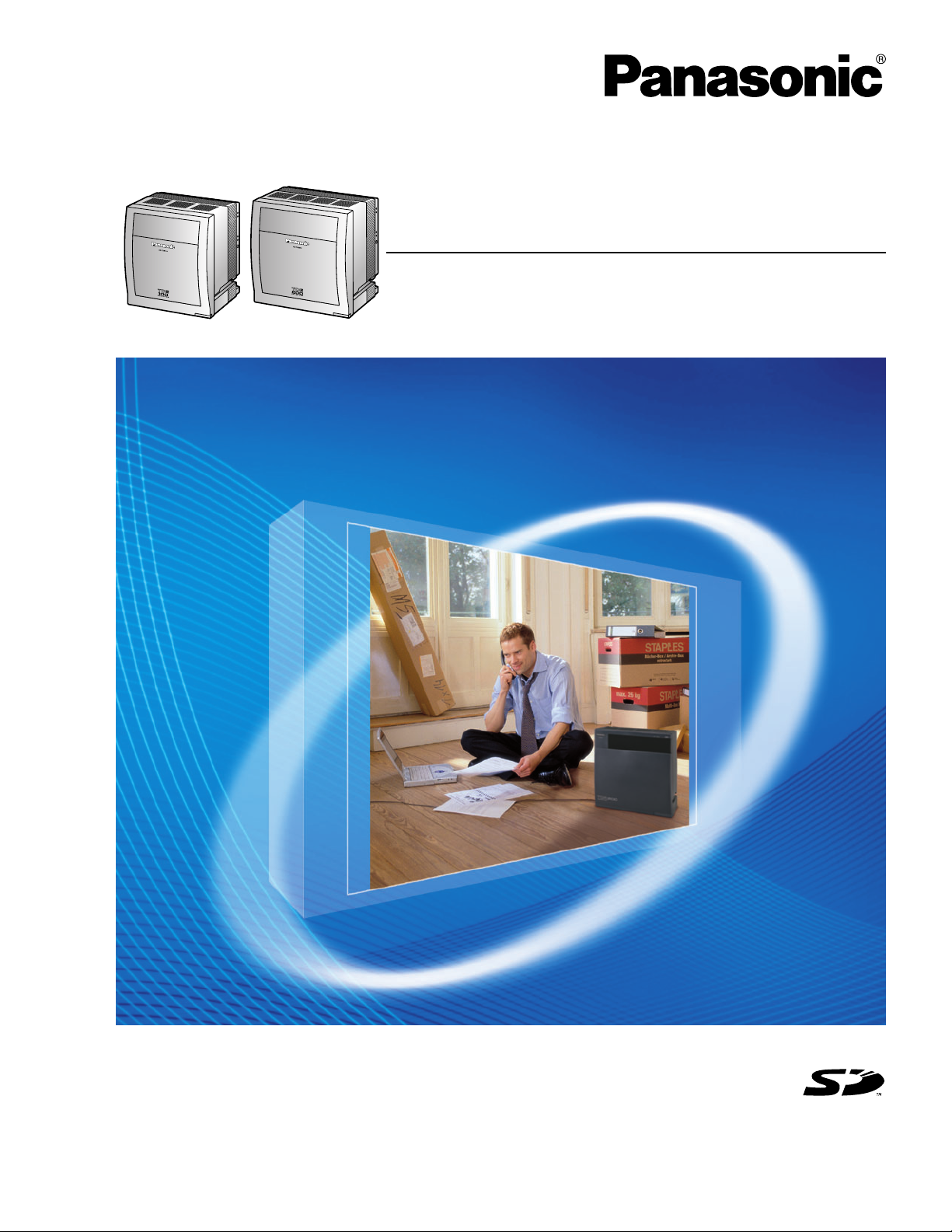
KX-TDE100
Model
KX-TDE200
Thank you for purchasing a Panasonic Pure IP-PBX.
Please read this manual carefully before using this product and save this manual for future use.
KX-TDE100/KX-TDE200: PMMPR Software File Version 1.0000 or later
Document Version: 2007-02
SD Logo is
a trademark.

System Components
System Components Table
Category Model No. Description
Shelves KX-TDE100 Basic Shelf
KX-TDE200 Basic Shelf
Main Processing Card IP Convergence Main Processing Card (IPCMPR)
IPCMPR Option Cards KX-TDE0110 16-Channel VoIP DSP Card (DSP16)
KX-TDE0111 64-Channel VoIP DSP Card (DSP64)
KX-TDA0196 Remote Card (RMT)
Activation Key Cards KX-NCS4104 4-Channel IP Trunk Activation Key (SHGW4)
KX-NCS4208 8-Channel IP Softphone/IP Proprietary Telephone Activation
Key (IPPTS8)
KX-NCS4508 8-Channel IP Proprietary Telephone Activation Key (IPPT8)
KX-NCS4716 16-Channel SIP Extension Activation Key (SPE16)
KX-NCS4910 Activation Key for Software Upgrade to Enhanced Version
(UCAV2)
Virtual CO Line Card - Virtual 16-Channel VoIP Gateway Card (V-IPGW16)
Virtual Extension Cards - Virtual 32-Channel VoIP Extension Card (V-IPEXT32)
- Virtual 32-Channel SIP Extension Card (V-SIPEXT32)
Physical CO Line Cards KX-TDA0180 8-Port Analog Trunk Card (LCOT8)
KX-TDA0181 16-Port Analog Trunk Card (LCOT16)
KX-TDA0187 T-1 Trunk Card (T1)
KX-TDA0193 8-Port Caller ID Card (CID8)
KX-TDA0290 PRI Card (PRI23)
KX-TDA0484 4-Channel VoIP Gateway Card (IP-GW4E)
KX-TDA0490 16-Channel VoIP Gateway Card (IP-GW16)
2 Installation Manual

System Components Table
Category Model No. Description
Physical Extension Cards KX-TDA0143 4 Cell Station Interface Card (CSIF4)
KX-TDA0144 8 Cell Station Interface Card (CSIF8)
KX-TDA0170 8-Port Digital Hybrid Extension Card (DHLC8)
KX-TDA0171 8-Port Digital Extension Card (DLC8)
KX-TDA0172 16-Port Digital Extension Card (DLC16)
KX-TDA0173 8-Port Single Line Telephone Extension Card (SLC8)
KX-TDA0174 16-Port Single Line Telephone Extension Card (SLC16)
KX-TDA0175 16-Port Single Line Telephone Extension with Message
Lamp Card (MSLC16)
KX-TDA0470 16-Channel VoIP Extension Card (IP-EXT16)
Other Physical Cards KX-TDA0161 4-Port Doorphone Card (DPH4)
KX-TDA0164 4-Port External Input/Output Card (EIO4)
KX-TDA0166 16-Channel Echo Canceller Card (ECHO16)
KX-TDA0168 Extension Caller ID Card (EXT-CID)
KX-TDA0190 Optional 3-Slot Base Card (OPB3)
KX-TDA0191 4-Channel Message Card (MSG4)
Power Supply Units
(PSUs)
KX-TDA0103 L-Type Power Supply Unit (PSU-L)
KX-TDA0104 M-Type Power Supply Unit (PSU-M)
KX-TDA0108 S-Type Power Supply Unit (PSU-S)
Cell
Stations
(CSs)
Basic CSs KX-T0141 2-Channel Cell Station Unit Using a DHLC/DLC Card (PT-
interface CS) for 2.4 GHz Portable Station
KX-TDA0142 3-Channel Cell Station Unit Using a CSIF Card for 2.4 GHz
Portable Station
KX-T0151 2-Channel Cell Station Unit Using a DHLC/DLC Card (PT-
interface CS) for 2.4 GHz Portable Station
KX-TDA0152 3/4-Channel Cell Station Unit Using a CSIF Card for 2.4 GHz
Portable Station
High-density
CSs
KX-TDA0158 5-Channel High-density Cell Station Unit Using a DHLC/DLC
Card (PT-interface CS) for 2.4 GHz Portable Station
Proprietary Equipment KX-A258 Blank Slot Cover
KX-T30865 Doorphone
Installation Manual 3

Compatible Panasonic Proprietary Telephones
The PBX supports the following telephones:
• IP proprietary telephones (e.g., KX-NT300 series)
• IP softphones (e.g., KX-NCS8100)
• Digital proprietary telephones (e.g., KX-T7600 series)
• Analog proprietary telephones (e.g., KX-T7700 series)
• Portable stations (e.g., KX-TD7690)
• DSS consoles (e.g., KX-T7640)
Note
KX-NT300 series IP-PTs are supported by the IPCMPR card, but not by the IP-EXT16 card. In contrast,
KX-NT136 and KX-NT265 IP-PTs are supported by the IP-EXT16 card, but not by the IPCMPR card.
Only the KX-NT265 (D) IP-PT is supported by both cards.
Incompatible Panasonic Proprietary Telephones
The PBX does not support the following telephones:
• KX-T30800 series proprietary telephones and DSS consoles
• KX-T61600 series proprietary telephones and DSS consoles
• KX-T123200 series proprietary telephones and DSS consoles
Notes
• For the equipment (e.g., Add-on Key Module, USB Module, Headset*1) that can be connected to a
particular telephone, refer to the telephone's manual.
• For other equipment that can be connected to the PBX, refer to "1.2.2 System Connection
Diagram".
List of Abbreviations
•APT → Analog Proprietary Telephone
•DPT → Digital Proprietary Telephone
• IP-PT → IP Proprietary Telephone
•PS → Portable Station
•PT → Proprietary Telephone
• SIP Extension → Session Initiation Protocol Extension (SIP hardphones/SIP softphones)
•SLT → Single Line Telephone
Notice
This PBX supports SIP Extensions. However, some PBX features may not be available for SIP
Extensions, depending on your telephone type.
*1
The KX-T7090 headset can be connected to the KX-T7000, KX-T7200, KX-T7300, and KX-T7400 series telephones.
4 Installation Manual

Important Notice
Prior to connection of this product, please verify that the intended operating environment is supported.
Satisfactory performance cannot be guaranteed for the following:
– interoperability and compatibility with all devices and systems connected to this product
– proper operation and compatibility with services provided by telecommunications companies over
connected networks
Installation Manual 5

Important Safety Instructions
SAFETY REQUIREMENTS
When using your telephone equipment, basic safety precautions should always be followed to reduce the
risk of fire, electric shock and injury to persons, including the following:
1. Read and understand all instructions.
2. Follow all warnings and instructions marked on the product.
3. Unplug the product from the wall outlet before cleaning. Do not use liquid cleaners or aerosol cleaners.
Clean with a damp cloth.
4. Do not use this product near water, for example, near a bathtub, wash bowl, kitchen sink, or laundry
tub, in a wet basement, or near a swimming pool.
5. Do not place the product on an unstable surface, as a fall may cause serious internal damage.
6. Slots and openings in the front, back and bottom of the cabinet are provided for ventilation; to protect
it from overheating, these openings must not be blocked or covered. The openings should never be
blocked by placing the product on a bed, sofa, rug, or other similar surface while in use. The product
should never be placed near or over a radiator or other heat source. This product should not be placed
in a sealed environment unless proper ventilation is provided.
7. The product should only be connected to the type of electrical power supply specified on the product
label. If you are not sure of the type of power supply to your home, consult your dealer or local power
company.
8. For safety purposes this unit is equipped with a grounded plug. If you do not have a grounded outlet,
please have one installed. Do not bypass this safety feature by tampering with the plug.
9. Do not allow anything to rest on the power cord. Do not locate this product where the power cord may
be stepped on or tripped on.
10. To reduce the risk of fire or electric shock, do not overload wall outlets and extension cords.
11. Do not insert objects of any kind into this product through its slots and openings, as they may touch
dangerous voltage points or short out parts that could result in a risk of fire or electric shock. Never spill
liquid of any kind on or in the product.
12. To reduce the risk of electric shock, do not disassemble this product. Only qualified personnel should
service this product. Opening or removing covers may expose you to dangerous voltages or other risks.
Incorrect reassembly can cause electric shock.
13. Unplug this product from the wall outlet and have it serviced by qualified service personnel in the
following cases:
a) When the power supply cord or plug is damaged or frayed.
b) If liquid has been spilled into the product.
c) If the product has been exposed to rain or water.
d) If the product does not operate according to the operating instructions. Adjust only the controls that
are explained in the operating instructions. Improper adjustment of other controls may result in
damage and may require service by a qualified technician to restore the product to normal
operation.
e) If the product has been dropped or the cabinet has been damaged.
f) If product performance deteriorates.
14. Avoid using wired telephones during an electrical storm. There is a remote risk of electric shock from
lightning.
15. Do not use a telephone in the vicinity of a gas leak to report the leak.
6 Installation Manual

SAVE THESE INSTRUCTIONS
Installation Manual 7

Precaution
WARNING
DO NOT REMOVE
SD MEMORY CARD
WHILE POWER IS
SUPPLIED TO THE PBX
Doing so may cause the PBX to fail to
start when you try to restart the system.
8 Installation Manual

• Keep the unit away from heating appliances and devices that generate electrical noise such as
C
fluorescent lamps, motors and televisions. These noise sources can interfere with the performance of
the PBX.
• This unit should be kept free of dust, moisture, high temperature (more than 40 ) and vibration, and
should not be exposed to direct sunlight.
• If you are having problems making calls to outside destinations, follow this procedure to test the CO
lines:
˚
1. Disconnect the PBX from all CO lines.
2. Connect known working SLTs to those CO lines.
3. Make a call to an external destination using those SLTs.
If a call cannot be carried out correctly, there may be a problem with the CO line that the SLT is
connected to. Contact your telephone company.
If all SLTs operate properly, there may be a problem with your PBX. Do not reconnect the PBX to the
CO lines until it has been serviced by an authorized Panasonic Factory Service Center.
• Wipe the unit with a soft cloth. Do not clean with abrasive powders or with chemical agents such as
benzene or thinner.
WARNING
• THIS UNIT MAY ONLY BE INSTALLED AND SERVICED BY QUALIFIED SERVICE
PERSONNEL.
• IF DAMAGE TO THE UNIT EXPOSES ANY INTERNAL PARTS, DISCONNECT THE
POWER SUPPLY CORD IMMEDIATELY AND RETURN THE UNIT TO YOUR DEALER.
• UNPLUG THIS UNIT FROM THE AC OUTLET IF IT EMITS SMOKE, AN ABNORMAL
SMELL OR MAKES UNUSUAL NOISE. THESE CONDITIONS CAN CAUSE FIRE OR
ELECTRIC SHOCK. CONFIRM THAT SMOKE HAS STOPPED AND CONTACT AN
AUTHORIZED PANASONIC FACTORY SERVICE CENTER.
• WHEN RELOCATING THE EQUIPMENT, FIRST DISCONNECT THE TELECOM
CONNECTION BEFORE DISCONNECTING THE POWER CONNECTION. WHEN THE
UNIT IS INSTALLED IN THE NEW LOCATION, RECONNECT THE POWER FIRST,
AND THEN RECONNECT THE TELECOM CONNECTION.
• TO PREVENT POSSIBLE FIRE OR ELECTRIC SHOCK, DO NOT EXPOSE THIS
PRODUCT TO RAIN OR MOISTURE.
• THE POWER SUPPLY CORD IS USED AS THE MAIN DISCONNECT DEVICE.
ENSURE THAT THE AC OUTLET IS LOCATED NEAR THE EQUIPMENT AND IS
EASILY ACCESSIBLE.
• DANGER OF EXPLOSION EXISTS IF A BATTERY IS INCORRECTLY REPLACED.
REPLACE ONLY WITH THE SAME OR EQUIVALENT TYPE RECOMMENDED BY THE
BATTERY MANUFACTURER. DISPOSE OF USED BATTERIES ACCORDING TO THE
MANUFACTURER'S INSTRUCTIONS.
• THE SD MEMORY CARD POSES A CHOKING HAZARD. KEEP THE SD MEMORY
CARD OUT OF REACH OF CHILDREN.
Installation Manual 9

Password Security
Warning to the Administrator or Installer regarding the system password
1. Please provide all system passwords to the customer.
2. To avoid unauthorized access and possible abuse of the PBX, keep the passwords secret, and
inform the customer of the importance of the passwords, and the possible dangers if they become
known to others.
3. The PBX has default passwords preset. For security, change these passwords the first time that
you program the PBX.
4. Change the passwords periodically.
5. It is strongly recommended that passwords of 10 numbers or characters be used for maximum
protection against unauthorized access. For a list of numbers and characters that can be used in
system passwords, refer to "1.1.2 Entering Characters" in the PC Programming Manual.
6. If a system password is forgotten, it can be found by loading a backup of the system data into a
PC, and checking the password using the KX-TDA Maintenance Console software. If you do not
have a backup of the system data, you must reset the PBX to its factory defaults and reprogram it.
Therefore, we strongly recommend maintaining a backup of the system data. For more information
on how to back up the system data, refer to "2.4.1 Tool—SD memory backup" in the PC
Programming Manual.
However, as system passwords can be extracted from backup copies of the system data file, do
not allow unauthorized access to these files.
Notice for users in California
This product contains a CR coin cell lithium battery that
contains perchlorate material—special handling may apply.
See www.dtsc.ca.gov/hazardouswaste/perchlorate
10 Installation Manual

When you ship the product
Carefully pack and send it prepaid, adequately insured and preferably in the original carton. Attach a
postage-paid letter, detailing the symptom, to the outside of the carton. DO NOT send the product to the
Executive or Regional Sales offices. They are NOT equipped to make repairs.
Product Service
Panasonic Factory Service Centers for this product are listed in the service center directory. Consult your
certified Panasonic dealer for detailed instructions.
For Future Reference
Please print, record, and retain the following information for future reference.
For Future Reference
Please print, record, and retain the following information for future reference.
Note
The serial number of this product can be found on the label affixed to the unit. You should record the
model number and the serial number of this unit as a permanent record of your purchase to aid in
identification in the event of theft.
MODEL NO.
SERIAL NO.
DATE OF PURCHASE
NAME OF DEALER
DEALER'S ADDRESS
DEALER'S TEL. NO.
Installation Manual 11

Introduction
This Installation Manual is designed to serve as an overall technical reference for the Panasonic Pure IPPBX, KX-TDE100/KX-TDE200. It provides instructions for installing the hardware, and programming the
PBX using the KX-TDE Maintenance Console.
The Structure of this Manual
This manual contains the following sections:
Section 1 System Outline
Provides general information on the PBX, including the system capacity and specifications.
Section 2 Activation Key Installation
Describes information on activation keys, including how to obtain an activation key and install it in the
SD Memory Card.
Section 3 Installation
Describes the procedures to install the PBX. Detailed instructions for planning the installation site,
installing the shelves and optional service cards, and cabling of peripheral equipment are provided.
Further information on system expansion and peripheral equipment installation is included.
Section 4 Guide for the KX-TDE Maintenance Console
Explains the installation procedure, structure, and basic information of the KX-TDE Maintenance
Console.
Section 5 Troubleshooting
Provides information on the PBX and telephone troubleshooting.
About the Other Manuals
Along with this Installation Manual, the following manuals are available:
Feature Manual
Describes all basic, optional and programmable features of the PBX.
PC Programming Manual
Provides step-by-step instructions for performing system programming using a PC.
PT Programming Manual
Provides step-by-step instructions for performing system programming using a PT.
Operating Manual
Provides operating instructions for end users using a PT, SLT, PS, or DSS Console.
About the software version of your PBX
The contents of this manual apply to PBXs with a certain software version, as indicated on the cover of this
manual. To confirm the software version of your PBX, see "How do I confirm the software version of the PBX
or installed cards?" in the FAQ of the PC Programming Manual, or "[190] Main Processing (MPR) Software
Version Reference" in the PT Programming Manual.
Trademarks
• The Bluetooth word mark and logos are owned by the Bluetooth SIG, Inc. and any use of such
marks by Matsushita Electric Industrial Co., Ltd. is under licence.
• Microsoft and Windows are either registered trademarks or trademarks of Microsoft Corporation in
the United States and/or other countries.
• Intel and Celeron are trademarks or registered trademarks of Intel Corporation or its subsidiaries
in the United States and other countries.
12 Installation Manual

• All other trademarks identified herein are the property of their respective owners.
• Screen shots reprinted with permission from Microsoft Corporation.
Installation Manual 13

F.C.C. REQUIREMENTS AND RELEVANT INFORMATION
1. Notification to the Telephone Company
This equipment complies with Part 68 of the FCC rules and the requirements adopted by the ACTA. On
the side of this equipment is a label that contains, among other information, a product identifier in the
following format:
• US:AAAEQ##TXXXX
If requested, this number must be provided to the telephone company.
Installation must be performed by a qualified professional installer. If required, provide the telephone
company with the following technical information:
• Telephone numbers to which the system will be connected
• Make: Panasonic
• Model: KX-TDE100 and KX-TDE200
• Certification No.: found on the side of the unit
• Ringer Equivalence No.: 0.3A
• Facility Interface Code: 02LS2, 04DU9.BN/DN/1KN/1SN, METALLIC
• Service Order Code: 9.0F, 6.0P
• Required Network Interface Jack: RJ21X, RJ48C, RJ2HX
2. Ringer Equivalence Number (REN)
The REN is used to determine the number of devices that may be connected to a telephone line.
Excessive RENs on a telephone line may result in the devices not ringing in response to an incoming
call. In most but not all areas, the sum of RENs should not exceed five (5.0). To be certain of the number
of devices that may be connected to a line, as determined by the total RENs, contact the local telephone
company. For products approved after July 23, 2001, the REN for this product is part of the product
identifier that has the following format:
• US:AAAEQ##TXXXX
The digits represented by ## are the REN without a decimal point (e.g., 03 is a REN of 0.3). For earlier
products, the REN is separately shown on the label.
3. Incidence of Harm to the Telephone Lines
If this equipment causes harm to the telephone network, the telephone company will notify you in
advance that temporary discontinuance of service may be required. But if advance notice isn't practical,
the telephone company will notify the customer as soon as possible. Also, you will be advised of your
right to file a complaint with the FCC if you believe it is necessary.
4. Changes in Telephone Company Communications Facilities, Equipment, Operations and
Procedures
The telephone company may make changes in its facilities, equipment, operations or procedures that
could affect the operation of the equipment. If this happens the telephone company will provide
advance notice in order for you to make necessary modifications to maintain uninterrupted service.
5. Trouble with this equipment
If trouble is experienced with this equipment, for repair or warranty information, please see the attached
warranty, which includes the Servicenter Directory. If the equipment is causing harm to the telephone
network, the telephone company may request that you disconnect the equipment until the problem is
resolved.
6. Connection to Party Line
Connection to party line service is subject to state tariffs. Contact the state public utility commission,
public service commission or corporation commission for information.
14 Installation Manual

7. Combined Use with Alarm Equipment
If your home has specially wired alarm equipment connected to the telephone line, ensure the
installation of this equipment does not disable your alarm equipment. If you have questions about what
will disable alarm equipment, consult your telephone company or a qualified installer.
Note
This equipment has been tested and found to comply with the limits for a Class B digital device,
pursuant to Part 15 of the FCC Rules. These limits are designed to provide reasonable protection
against harmful interference in a residential installation. This equipment generates, uses, and can
radiate radio frequency energy and, if not installed and used in accordance with the instructions, may
cause harmful interference to radio communications. However, there is no guarantee that interference
will not occur in a particular installation. If this equipment does cause harmful interference to radio or
television reception, which can be determined by turning the equipment off and on, the user is
encouraged to try to correct the interference by one or more of the following measures:
• Reorient or relocate the receiving antenna.
• Increase the separation between the equipment and receiver.
• Connect the equipment into an outlet on a circuit different from that to which the receiver is
connected.
• Consult the dealer or an experienced radio/TV technician for help.
CAUTION
Any changes or modifications not expressly approved by the party responsible for compliance could
void the user's authority to operate this device.
When programming emergency numbers and/or making test calls to emergency numbers:
1. Remain on the line and briefly explain to the dispatcher the reason for the call before hanging up.
2. Perform such activities in the off-peak hours, such as early morning hours or late evenings.
WARNING
The software contained in the ARS and TRS features to allow user access to the
network must be upgraded to recognize newly established network area codes and
exchange codes as they are placed into service. Failure to upgrade the on-premise
PBXs or peripheral equipment to recognize the new codes as they are established will
restrict the customer and users of the PBX from gaining access to the network and to
these codes.
KEEP THE SOFTWARE UP-TO-DATE WITH THE LATEST DATA.
Installation Manual 15

For Cell Station
CAUTION
Any changes or modifications not expressly approved by the party responsible for compliance could
void user's authority to operate this device.
Note
This equipment has been tested and found to comply with the limits for a Class B digital device,
pursuant to Part 15 of the FCC Rules. These limits are designed to provide reasonable protection
against harmful interference in a residential installation. This equipment generates, uses, and can
radiate radio frequency energy and, if not installed and used in accordance with the instructions, may
cause harmful interference to radio communications. However, there is no guarantee that interference
will not occur in a particular installation. If this equipment does cause harmful interference to radio or
television reception, which can be determined by turning the equipment off and on, the user is
encouraged to try to correct the interference by one or more of the following measures:
• Reorient or relocate the receiving antenna.
• Increase the separation between the equipment and receiver.
• Connect the equipment into an outlet on a circuit different from that to which the receiver is
connected.
• Consult the dealer or an experienced radio/TV technician for help.
Some wireless telephones operate at frequencies that may cause interference to nearby TVs and
VCRs. To minimize or prevent such interference, the base of the wireless telephone should not be
placed near or on top of a TV or VCR. If interference is experienced, move the wireless telephone
further away from the TV or VCR. This will often reduce, or eliminate, interference.
Operating near 2.4 GHz electrical appliances may cause interference. Move away from the electrical
appliances.
CAUTION
To comply with FCC RF exposure requirements in uncontrolled environment:
• This equipment must be installed and operated in accordance with provided instructions and a
minimum 20 cm (8 in) spacing must be provided between antenna and all person's body (excluding
extremities of hands, wrist and feet) during wireless modes of operation.
• This transmitter must not be co-located or operated in conjunction with any other antenna or
transmitter.
Medical—consult the manufacturer of any personal medical devices, such as pacemakers, to
determine if they are adequately shielded from external RF (radio frequency) energy. (The unit operates
in the frequency range of 2401 MHz to 2480 MHz, and the power output level can range from 0.004 W
to 0.4 W.) Do not use the unit in health care facilities if any regulations posted in the area instruct you
not to do so. Hospitals or health care facilities may be using equipment that could be sensitive to
external RF (radio frequency) energy.
16 Installation Manual

Table of Contents
1 System Outline ..................................................................................... 21
1.1 System Highlights .......................................................................................................... 22
1.1.1 System Highlights ............................................................................................................. 22
1.2 Basic System Construction ........................................................................................... 26
1.2.1 Basic Shelf........................................................................................................................ 26
1.2.2 System Connection Diagram ............................................................................................27
1.3 Optional Equipment........................................................................................................29
1.3.1 Optional Equipment ..........................................................................................................29
1.4 Specifications ................................................................................................................. 31
1.4.1 General Description .......................................................................................................... 31
1.4.2 Characteristics .................................................................................................................. 33
1.4.3 System Capacity............................................................................................................... 34
2 Activation Key Installation ................................................................... 41
2.1 Information about the Activation Keys .........................................................................42
2.1.1 Activation Keys.................................................................................................................. 42
2.1.2 Activation Key Card and Key Management System.......................................................... 44
2.1.3 Activation Key File............................................................................................................. 45
3 Installation............................................................................................. 47
3.1 Before Installation........................................................................................................... 48
3.1.1 Before Installation ............................................................................................................. 48
3.2 Installation of the PBX.................................................................................................... 50
3.2.1 Unpacking ......................................................................................................................... 50
3.2.2 Names and Locations .......................................................................................................51
3.2.3 Opening/Closing the Front Cover...................................................................................... 52
3.2.4 Installing/Replacing the Power Supply Unit ......................................................................54
3.2.5 Frame ground Connection ................................................................................................58
3.2.6 Installing/Removing the Optional Service Cards .............................................................. 59
3.2.7 Types of Connectors ......................................................................................................... 64
3.2.8 Attaching a Ferrite Core .................................................................................................... 66
3.2.9 Fastening an Amphenol Connector .................................................................................. 68
3.2.10 Wall Mounting (KX-TDE200).............................................................................................70
3.2.11 Wall Mounting (KX-TDE100).............................................................................................72
3.2.12 Floor Standing (KX-TDE200 Only).................................................................................... 74
3.2.13 Surge Protector Installation ..............................................................................................76
3.3 Information about the Main Processing Card .............................................................. 79
3.3.1 IPCMPR Card ................................................................................................................... 79
3.3.2 DSP16 Card (KX-TDE0110) and DSP64 Card (KX-TDE0111) ........................................82
3.3.3 RMT Card (KX-TDA0196).................................................................................................83
3.4 Information about the Virtual Cards.............................................................................. 84
3.4.1 Virtual Cards ..................................................................................................................... 84
3.5 Information about the Physical Trunk Cards................................................................ 85
3.5.1 LCOT8 Card (KX-TDA0180) and LCOT16 Card (KX-TDA0181).......................................85
3.5.2 CID8 Card (KX-TDA0193) ................................................................................................87
3.5.3 T1 Card (KX-TDA0187) .................................................................................................... 88
3.5.4 PRI23 Card (KX-TDA0290)............................................................................................... 90
3.5.5 IP-GW4E Card (KX-TDA0484) ......................................................................................... 92
Installation Manual 17

3.5.6 IP-GW16 Card (KX-TDA0490) ..........................................................................................94
3.6 Information about the Physical Extension Cards ........................................................96
3.6.1 CSIF4 Card (KX-TDA0143) and CSIF8 Card (KX-TDA0144) ...........................................96
3.6.2 DHLC8 Card (KX-TDA0170) .............................................................................................99
3.6.3 DLC8 Card (KX-TDA0171)..............................................................................................102
3.6.4 DLC16 Card (KX-TDA0172)............................................................................................104
3.6.5 SLC8 Card (KX-TDA0173)..............................................................................................106
3.6.6 EXT-CID Card (KX-TDA0168).........................................................................................108
3.6.7 SLC16 Card (KX-TDA0174) and MSLC16 Card (KX-TDA0175).....................................109
3.6.8 IP-EXT16 Card (KX-TDA0470) .......................................................................................111
3.7 Information about the Other Physical Cards ..............................................................113
3.7.1 OPB3 Card (KX-TDA0190) .............................................................................................113
3.7.2 DPH4 Card (KX-TDA0161) .............................................................................................114
3.7.3 EIO4 Card (KX-TDA0164)............................................................................................... 116
3.7.4 ECHO16 Card (KX-TDA0166) ........................................................................................119
3.7.5 MSG4 Card (KX-TDA0191).............................................................................................120
3.8 Connection of Extensions............................................................................................121
3.8.1 Maximum Cabling Distances of the Extension Wiring (Twisted Cable)...........................121
3.8.2 Parallel Connection of the Extensions ............................................................................123
3.8.3 Digital EXtra Device Port (Digital XDP) Connection........................................................126
3.8.4 First Party Call Control CTI Connection..........................................................................128
3.9 Connection of 2.4 GHz Portable Stations ...................................................................129
3.9.1 Overview ......................................................................................................................... 129
3.9.2 Procedure Overview........................................................................................................131
3.9.3 Site Planning................................................................................................................... 133
3.9.4 Before Site Survey .......................................................................................................... 137
3.9.5 Site Survey...................................................................................................................... 141
3.9.6 After Site Survey ............................................................................................................. 145
3.9.7 Connecting a Cell Station to the PBX .............................................................................146
3.9.8 Wall Mounting .................................................................................................................155
3.10
3.10.1
3.11 Connection of Peripherals ...........................................................................................162
3.11.1 Connection of Peripherals...............................................................................................162
3.12 LAN Connection............................................................................................................166
3.12.1 LAN Connection..............................................................................................................166
3.13 Power Failure Connections..........................................................................................167
3.13.1 Power Failure Connections .............................................................................................167
3.14 Starting the PBX............................................................................................................169
3.14.1 Starting the PBX .............................................................................................................169
Connection of Doorphones, Door Openers, External Sensors, and External Relays
Connection of Doorphones, Door Openers, External Sensors, and External Relays
........... 159
............ 159
4 Guide for the KX-TDE Maintenance Console ................................... 171
4.1 Overview ........................................................................................................................ 172
4.1.1 Overview ......................................................................................................................... 172
4.2 Connection ....................................................................................................................173
4.2.1 Connection......................................................................................................................173
4.3 Installation of the KX-TDE Maintenance Console......................................................175
4.3.1 Installing and Starting the KX-TDE Maintenance Console .............................................175
5 Troubleshooting.................................................................................. 179
5.1 Troubleshooting ............................................................................................................180
18 Installation Manual

5.1.1 Installation....................................................................................................................... 180
5.1.2 Connection...................................................................................................................... 183
5.1.3 Operation ........................................................................................................................ 185
5.1.4 Using the Reset Button ................................................................................................... 187
5.1.5 Troubleshooting by Error Log..........................................................................................188
Index .......................................................................................................... 191
Installation Manual 19

20 Installation Manual

Section 1
System Outline
This section provides general information on the PBX,
including the system capacity and specifications.
Installation Manual 21

1.1 System Highlights
1.1 System Highlights
1.1.1 System Highlights
IPCMPR Card Features
The IPCMPR card (the pre-installed Main Processing card) includes the following features and resources:
VoIP CO Lines/VoIP Extensions
The IPCMPR card allows the use of IP CO lines (H.323) and IP telephones (IP-PTs, IP softphones, and
SIP Extensions). By connecting a DSP card to the IPCMPR card, these IP CO lines and extensions can
be used. It is also possible to increase the number of IP CO lines (max. 32) and extensions (max. 128)
through the purchase of activation key cards.
LAN Connection
The IPCMPR card comes included with a Local Area Network (LAN) port (RJ45 port) allowing for the
PBX to be connected to a LAN.
Computer Telephony Integration (CTI) Features
Connecting a PC to a DPT, or connecting a CTI Server to this PBX, allows functions of the PC, PBX
and extensions to be integrated. For example, detailed caller information can be taken from a database
and displayed on the PC as a call arrives, or the PC can dial numbers for the extension automatically.
Simplified Voice Message (SVM) Features
The IPCMPR card comes pre-installed with the SVM feature (2 channels), allowing for simple
answering machine services to be supported.
Internet Protocol (IP) Telephone Features
This PBX supports the following telephone features that use IP:
IP-PT Features
This PBX supports the connection of IP-PTs which function almost identically to normal PTs. However,
they connect to the PBX over a LAN and make and receive calls using IP. In addition, KX-NT300 series
IP-PTs support the following features:
– Self Labelling (KX-NT366 only)
The LCDs featured next to the 12 flexible buttons of the KX-NT366 can be programmed to display
information regarding the setting of the corresponding flexible button. In addition, the flexible
buttons can be organized into 4 “pages” allowing you to assign a total of 4 items to each physical
button.
– Optional Modules
• KX-NT307(PSLP1528) Bluetooth Module:
Allows for a Bluetooth wireless headset to be connected to a KX-NT300 series IP-PT.
• KX-NT303 Add-on 12 Key Module:
Allows for 12 additional flexible buttons to be connected to a KX-NT346 or KX-NT343.
• KX-NT305 Add-on 60 Key Module:
Allows for 60 additional flexible buttons to be connected to a KX-NT346 or KX-NT343.
– High Sound Quality
®
22 Installation Manual

Calls between KX-NT300 series IP-PTs support G.722 CODEC allowing for high sound quality
conversations.
SIP (Session Initiation Protocol) Extensions
This PBX supports the connection of third party SIP supported IP telephones (hardphones and
softphones). SIP Extensions make and receive calls using IP.
IP Softphones
This PBX supports the connection of Panasonic IP softphones, providing IP-PT operations and features
using software on a PC.
Internet Protocol (IP) Related Features
Server Connection
This PBX supports the connection to the following servers, allowing for enhanced efficiency and record
keeping:
– SNMP Server:
Allows for users assigned as SNMP managers to manage and receive PBX system status
information, such as local alarm information and general system activity using Simple Network
Management Protocol (SNMP).
– SNTP Server:
Allows for the PBX to automatically receive and update the time setting using Simple Network Time
Protocol (SNTP).
– DHCP Server:
Allows for this PBX to receive IP addresses from a Dynamic Host Configuration Protocol (DHCP)
server.
1.1 System Highlights
Peer-to-peer Connection
Intercom calls can be made between peer-to-peer compatible IP extensions allowing for
communication without using the PBX's VoIP resources.
Networking Features
This PBX supports the following networking features:
Voice over Internet Protocol (VoIP) Network
The PBX can connect to another PBX via a private IP network. In this case, voice signals are converted
into IP packets and sent through this network. Automatic rerouting of VoIP calls to public CO lines is
also available, in case of network difficulties.
TIE Line Service
A TIE line is a privately leased communication line between two or more PBXs, which provides cost
effective communications between company members at different locations.
Virtual Private Network (VPN)
VPN is a service provided by the VPN service provider. It uses an existing public line as if it were a
private line.
QSIG Network
QSIG is a protocol based on ISDN (Q.931) and offers enhanced PBX features in a private network of
two or more connected PBXs.
Installation Manual 23

1.1 System Highlights
External Device Support
The following are just a few of the many useful optional devices available to enhance your telephony system:
Portable Station (PS) Features
PSs can be connected to this PBX. It is possible to use the PBX features using the PS like a PT. This
PBX supports basic CSs (allows up to 4 PSs to be on a call simultaneously) as well as high-density
CSs (allows up to 8 PSs to be on a call simultaneously). A PS can also be used in parallel with a wired
telephone (Wireless XDP Parallel Mode). In this case, the wired telephone is the main telephone and
the PS is the sub telephone.
Cellular Phone Features (KX-NCS4910 required)
This PBX supports the use of cellular phones destinations with the PBX. In combination with the use
of certain features such as Virtual PS, DISA, and XDP Parallel mode, cellular phones can make and
receive calls as if they were registered extensions.
Phone Assistant (PA) Pro Series
This PBX supports KX-TDA Phone Assistant Pro Series applications, a collection of highly-intuitive CTI
applications that allow you to use your PC to access a variety of PBX features conveniently and
efficiently. PA Pro series applications combine the efficiency and user-friendliness of CTI applications
with the convenience of server-based applications, allowing User IDs, passwords and PBX settings to
be configured over a web browser.
Voice Mail Features
This PBX supports Voice Processing Systems (VPS) with DTMF Integration as well as DPT (Digital)
Integration, connected locally and over a network.
ACD Report Server (KX-NCV200)
This PBX supports VPSs with an ACD Report Server. In addition to VPS features, the ACD Report
Server provides you with a variety of features, such as monitoring, reporting, call logging features and
creating performance graphs, to manage call information efficiently.
Other Useful Features
Easy Installation and Setup
– With Physical Cards
By simply connecting telephones and outside lines to analog extension and CO line cards you can
make and receive calls. For digital CO lines (e.g., T1, etc.), it may be necessary to first make the
required settings and restart the PBX.
– With Virtual Cards
By connecting the PBX to the LAN, installing each virtual card and registering the IP telephones
through system programming, you can make and receive calls.
Enhanced Walking Extension Feature
It is possible to use the Walking Extension feature with extensions in Service-in (functions normally)
and Service-out (cannot make CO line calls or receive calls) modes, allowing users to use their
extensions at home and at work, or for multiple users who work in shifts to use their own extension
settings on a single telephone.
24 Installation Manual

Built-in Small Call Centre Features
An incoming call distribution (ICD) group can be used as a small call centre with the following features:
– Queuing Feature
When a preprogrammed number of extensions in an ICD group are busy, additional incoming calls
can wait in a queue. While callers are waiting in the queue, they can be sent an outgoing message
(OGM) informing the caller of the current situation, or be redirected to another destination or
disconnected depending on the amount of time the caller has been waiting.
– Log-in/Log-out
ICD group members can join (Log-in) or leave (Log-out) their groups manually. After a call is
completed, a preprogrammed time period where users will not receive calls can be assigned
(Wrap-up). This gives time for users to make reports about the previous call without be interrupted
or allows users to not receive calls while they are taking a break.
– VIP Call
The VIP Call feature is one method of making sure that calls from preferred customers or callers
are answered quickly. When using VIP Call mode, ICD groups are assigned a priority, allowing calls
in higher-priority groups to be answered before calls in lower-priority groups.
Hospitality Features
This PBX has several features allowing it to be used effectively and efficiently in a hotel-type
environment. These features allow extensions assigned as hotel operators to change and monitor the
room status of guest rooms, check or set wake-up calls, and print out records of guest charges.
1.1 System Highlights
Installation Manual 25
1.2 Basic System Construction
1.2 Basic System Construction
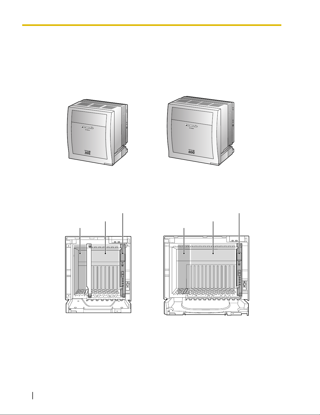
1.2.1 Basic Shelf
The basic shelf contains an IPCMPR card for controlling the PBX. To use the system, install a power supply
unit (PSU) in the PSU Slot and optional service cards in the basic shelf.
KX-TDE100 KX-TDE200
Construction of the Basic Shelf
IPCMPR Card
Free Slots
PSU Slot
IPCMPR Card
Free Slots
PSU Slot
26 Installation Manual
KX-TDE100 KX-TDE200

1.2.2 System Connection Diagram
CO (Telephone Company) Lines
Analog/PRI/T1
Remote PC
1.2 Basic System Construction
Private
IP Network
Batteries
PC
Printer
External Sensor/
External Relay Device
Pure IP-PBX
Fax Machine
Wireless Phone
ISDN Telephone
SLT
APT
DPT
Router
PC
IP-PT
IP Softphone
SIP Extension
DSS Console
CTI Server
DSS Console
Doorphone & Door Opener
BGM/Music On Hold (MOH)
Pager/
Speaker
Amplifier
CSPS
Voice Processing
System
USB
KX-T7636/
KX-T7633
KX-T7600 DPT KX-T7600 DPT
PC
PC
PC
Installation Manual 27
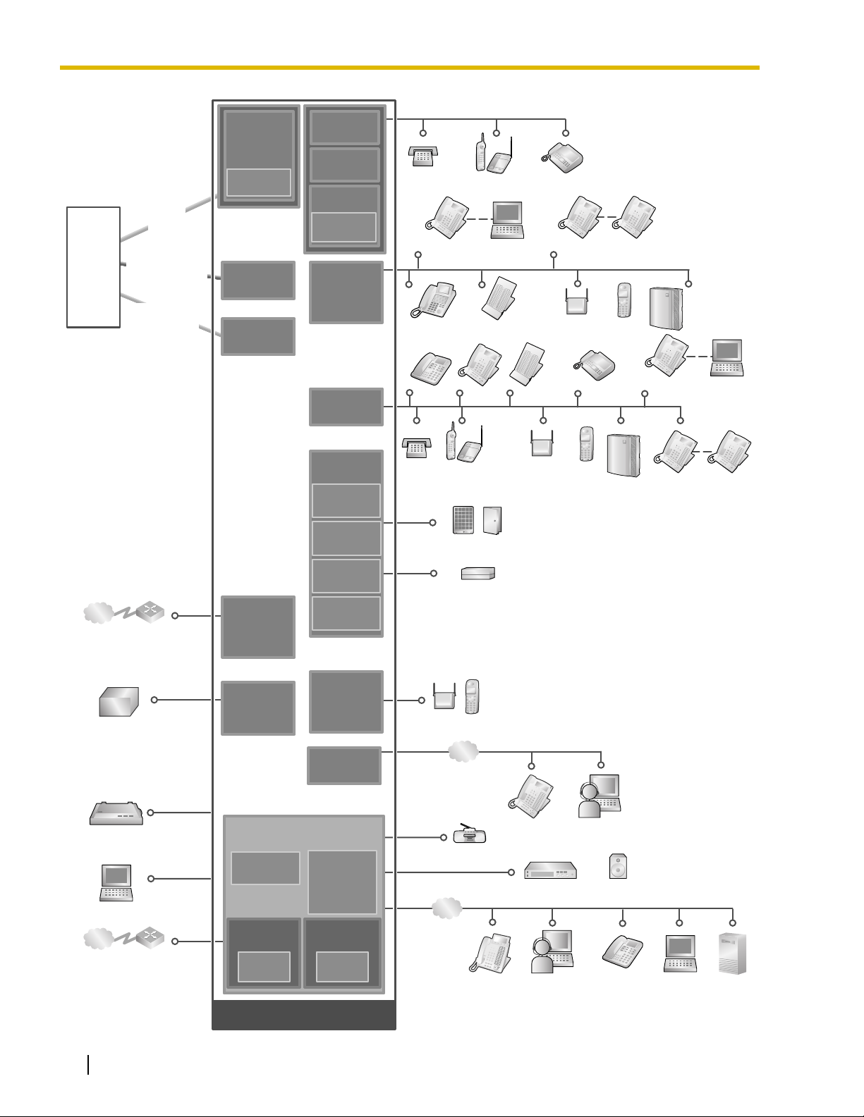
1.2 Basic System Construction
Telephone
Company
Analog
CO Line
ISDN PRI Line
(Digital CO Line)
T1 Line
(Digital CO Line)
LCOT4
LCOT16
(KX-TDA0183)
(KX-TDA0181)
LCOT8
(KX-TDA0180)
CID8
(KX-TDA0193)
PRI23
(KX-TDA0290)
T1
(KX-TDA0187)
MSLC16
(KX-TDA0175)
SLC16
(KX-TDA0174)
SLC8
(KX-TDA0173)
EXT-CID
(KX-TDA0168)
DLC16
(KX-TDA0172)
DLC8
(KX-TDA0171)
DHLC8
(KX-TDA0170)
OPB3
(KX-TDA0190)
DPH4
(KX-TDA0161)
SLT Wireless Phone Fax Machine
KX-T7636/
KX-T7633
DPT
APT DPT DSS Console
SLT Wireless Phone
PC
DSS Console
PT-interface CS
(Basic/High-density)
KX-T7600
DPT
PT-interface CS
(Basic/High-density)
Fax Machine
PS
KX-T7600
DPT
PS
Voice
Processing
System
Voice
Processing
System
KX-T7636/
KX-T7633
KX-T7600
DPT
PC
KX-T7600
DPT
Private IP
Network
Uninterruptible
Power Supply (UPS)
Station Message
Detail Recording (SMDR)
Private IP
Network
Router
PC
Router
IP-GW4E
(KX-TDA0484)
IP-GW16
(KX-TDA0490)
PSU-S/M/L
(KX-TDA0108/
KX-TDA0104/
KX-TDA0103)
IPCMPR
(Installed by default)
RMT
(KX-TDA0196)
Virtual Trunk
Slot
V-IPGW16
EIO4
(KX-TDA0164)
ECHO16
(KX-TDA0166)
MSG4
(KX-TDA0191)
CSIF4
(KX-TDA0143)
CSIF8
(KX-TDA0144)
IP-EXT16
(KX-TDA0470)
DSP16
(KX-TDE0110)
DSP64
(KX-TDE0111)
Virtual
Extension Slot
V-IPEXT32
V-SIPEXT32
Doorphone & Door Opener
External Sensor/External Relay Device
CS PS
LAN
LAN
Radio
IP-PT
IP-PT
IP Softphone
IP Softphone
Amplifier Pager/Speaker
SIP Extension
PC
CTI Server
28 Installation Manual
Mountable Equipment

1.3 Optional Equipment
1.3 Optional Equipment
1.3.1 Optional Equipment
Model No. Model Name Description
KX-TDE0110 16-Channel VoIP DSP Card (DSP16) 16-channel digital signal processor card with an
SHGW4 activation key and an IPPT8 activation key
pre-installed. Compliant with ITU-T G.729a and
G.711 CODEC methods. To be mounted on the
IPCMPR card.
KX-TDE0111 64-Channel VoIP DSP Card (DSP64) 64-channel digital signal processor card with four
SHGW4 activation keys and four IPPT8 activation
keys pre-installed. Compliant with ITU-T G.729a
and G.711 CODEC methods. To be mounted on the
IPCMPR card.
KX-TDA0103 L-Type Power Supply Unit (PSU-L) Power Supply Unit for the KX-TDE200. Total power
output of 279 W. Safety Class 1 compliant.
KX-TDA0104 M-Type Power Supply Unit (PSU-M) Power Supply Unit for the KX-TDE100 and KX-
TDE200. Total power output of 140.4 W. Safety
Class 1 compliant.
KX-TDA0108 S-Type Power Supply Unit (PSU-S) Power Supply Unit for the KX-TDE100. Total power
output of 74 W. Safety Class 1 compliant.
KX-TDA0143 4 Cell Station Interface Card (CSIF4) 4-port CS interface card for 4 CSs.
KX-TDA0144 8 Cell Station Interface Card (CSIF8) 8-port CS interface card for 8 CSs.
KX-TDA0161 4-Port Doorphone Card (DPH4) 4-port doorphone card for 4 doorphones and 4 door
openers. To be mounted on the OPB3 card.
KX-TDA0164 4-Port External Input/Output Card
(EIO4)
KX-TDA0166 16-Channel Echo Canceller Card
(ECHO16)
KX-TDA0168 Extension Caller ID Card (EXT-CID) Sends Caller ID signals to extension ports. To be
KX-TDA0170 8-Port Digital Hybrid Extension Card
(DHLC8)
KX-TDA0171 8-Port Digital Extension Card (DLC8) 8-port digital extension card for DPTs, DSS
4-port external input/output card. To be mounted on
the OPB3 card.
16-channel card for echo cancellation during
conferences. To be mounted on the OPB3 card.
mounted on the SLC8 card only.
8-port digital hybrid extension card for DPTs, APTs,
SLTs, DSS consoles, and PT-interface CSs (Basic/
High-density), with 2 power failure transfer (PFT)
ports.
consoles, and PT-interface CSs (Basic/Highdensity).
KX-TDA0172 16-Port Digital Extension Card
(DLC16)
16-port digital extension card for DPTs, DSS
consoles, and PT-interface CSs (Basic/Highdensity).
Installation Manual 29

1.3 Optional Equipment
Model No. Model Name Description
KX-TDA0173 8-Port Single Line Telephone
Extension Card (SLC8)
KX-TDA0174 16-Port Single Line Telephone
Extension Card (SLC16)
KX-TDA0175 16-Port Single Line Telephone
Extension with Message Lamp Card
(MSLC16)
8-port extension card for SLTs with 2 power failure
transfer (PFT) ports.
16-port extension card for SLTs with 4 power failure
transfer (PFT) ports.
16-port extension card for SLTs with Message
Waiting Lamp control and 4 power failure transfer
(PFT) ports. Maximum power output of 160 V/90 V
for Message Waiting Lamp control.
KX-TDA0180 8-Port Analog Trunk Card (LCOT8) 8-port analog CO line card with 2 power failure
transfer (PFT) ports.
KX-TDA0181 16-Port Analog Trunk Card (LCOT16) 16-port analog CO line card with 4 power failure
transfer (PFT) ports.
KX-TDA0187 T-1 Trunk Card (T1) 1-port T1 CO line card. EIA/TIA standard compliant.
KX-TDA0190 Optional 3-Slot Base Card (OPB3) Optional 3-slot base card for mounting a maximum
of 3 option cards from the following: MSG4, DPH4,
or ECHO16 card.
KX-TDA0191 4-Channel Message Card (MSG4) 4-channel message card. To be mounted on the
OPB3 card.
KX-TDA0193 8-Port Caller ID Card (CID8) 8-port Caller ID signal type FSK/FSK (with Call
Waiting Caller ID [Visual Caller ID])/DTMF. To be
mounted on the LCOT8/LCOT16 cards.
KX-TDA0196 Remote Card (RMT) Analog modem card for remote communication with
the PBX. ITU-T V.90 support. To be mounted on the
IPCMPR card.
KX-TDA0290 PRI Card (PRI23) 1-port ISDN Primary Rate Interface card (23B
channels). NI (North American standard ISDN
protocol) compliant.
KX-TDA0470 16-Channel VoIP Extension Card (IP-
EXT16)
16-channel VoIP extension card. Compliant with
Panasonic proprietary protocol, and ITU-T G.729a
and G.711 CODEC methods.
KX-TDA0484 4-Channel VoIP Gateway Card (IP-
GW4E)
4-channel VoIP gateway card. Compliant with VoIP
H.323 V.2 protocol, and ITU-T G.729a, G.723.1 and
G.711 CODEC methods.
KX-TDA0490 16-Channel VoIP Gateway Card (IP-
GW16)
16-channel VoIP gateway card. Compliant with VoIP
H.323 V.2 protocol, and ITU-T G.729a, G.723.1 and
G.711 CODEC methods.
Note
For the maximum number of optional service cards that can be installed in the PBX, refer to "1.4.3
System Capacity".
30 Installation Manual
 Loading...