

Panasonic 96NKX HTS824 Users Manual
Getting Started
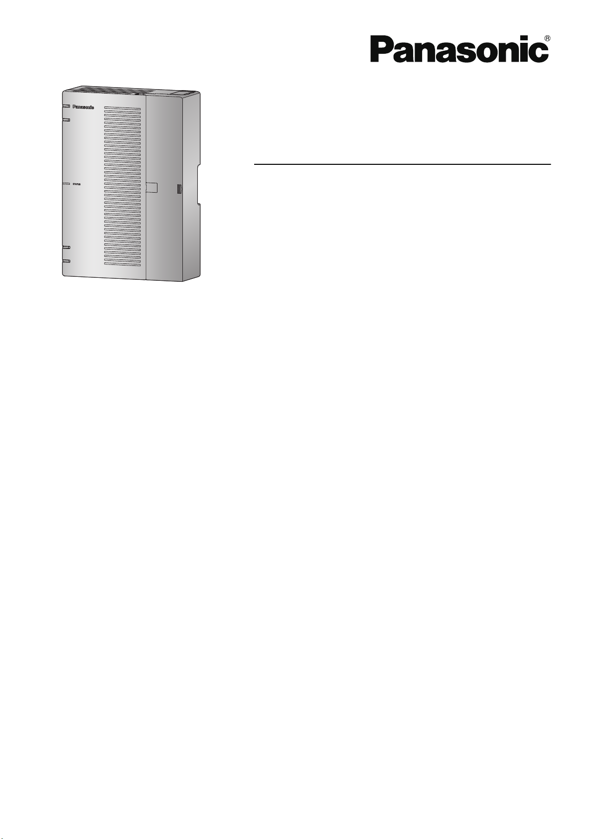
Hybrid IP-PBX
Model No.
KX-HTS824
KX-HTS32
Thank you for purchasing this Panasonic product.
Please read this manual carefully before using this product and save this manual for future use.
In particular, be sure to read "1.1 For Your Safety, page 8" before using this product.
KX-HTS: Series (KX-HTS824 KX-HTS32) : PJMPR Software File Version 001.00000 or later
Manuals and supporting information are provided on the Panasonic Web site at:
http://www.panasonic.net/pcc/support/pbx/

System Components
System Components
System Components for KX-HTS Series
Category Model No. Description
Main Unit KX-HTS824
KX-HTS32
Physical Cards KX-HT82480 4 ports Analogue Trunk interface with Caller ID
KX-HT82470 8 ports Standard Telephone Line Interface with Caller
KX-HT82460 2 ports Panasonic Proprietary Door phone Interface
Proprietary Equipment KX-A227 Backup battery cable
Main Unit
(LCOT4)
ID (SLC8)
with door opener (no sensor interface) (DPH2)
Equipment Compatibility for Main Unit
The PBX supports the following equipment:
Doorphones
Doorphone (KX-T30865, KX-T7765)
•
SIP Phones
Refer to the Panasonic Web site for information on compatible terminals.
•
Other
Single line telephones
•
Note
For the equipment that can be connected to a particular telephone, refer to the telephone's manual.
•
Notice
This PBX supports SIP extensions. However, some PBX features may not be available depending on
•
the type of telephone.
Under power failure conditions, the connected telephones may not operate. Please ensure that a sepa-
•
rate telephone, not dependent on local power, is available for emergency use.
Prior to connection of this product, please verify that the intended operating environment is supported.
•
Satisfactory performance cannot be guaranteed for the following:
interoperability and compatibility with all devices and systems connected to this product
–
proper operation and compatibility with services provided by telecommunications companies over
–
connected networks
Note
Some optional hardware, software, and features are not available in some countries/areas. Please
•
consult your certified Panasonic dealer for more information.
In this manual, the suffix of each model number (e.g., KX-HTS824BX) is omitted unless necessary.
•
List of Abbreviations
SIP Extension -> Extensions of the PBX which use Session Initiation Protocol for communication.
•
SLT -> Single Line Telephone
•
2

P-SIP -> Panasonic SIP Phones (KX-HDV series)
•
System Components
3

Introduction
Introduction
This Manual is designed to serve as an overall technical reference for the Panasonic KX-HTS824 and
KX-HTS32 IP-PBXs. It provides instructions for installing the hardware, and programming the PBX using
Web Based programming.
The Structure of this Manual
This manual contains the following sections:
Section 1 Safety Precautions
Provides important information intended to prevent personal injury and property damage.
Section 2 System Outline
Provides general information on the PBX, including the system capacity and specifications.
Section 3 Installation
Describes the procedures to install the PBX. Detailed instructions for planning the installation site, optional service cards, and cabling of peripheral equipment are provided.
Section 4 Confirming Connections
Making and receiving calls with extensions and trunks.
Section 5 Maintenance
Maintenance procedures.
Section 6 Troubleshooting
Provides information on the PBX and telephone troubleshooting.
Section 7 Appendix
Provides information about System Prompt Languages and the revision history.
About the Other Manuals
In addition to this Manual, the following manuals are available:
Programming Item List (PI)
Provides step-by-step instructions for performing system programming using a PC.
Feature Manual (FM)
Describes all basic, optional and programmable features of the PBX.
About the software version of your PBX
The contents of this manual apply to PBXs with a certain software version, as indicated on the cover of this
manual. To confirm the software version of your PBX, see "Maintenance-Version Information" in the Programming Item List.
Trademarks
Microsoft is a registered trademark or trademark of Microsoft Corporation in the United States and/or
•
other countries.
All other trademarks identified herein are the property of their respective owners.
•
Microsoft product screen shot(s) reprinted with permission from Microsoft Corporation.
•
4

Table of Contents
Table of Contents
1 Safety Precautions ................................................................................. 7
1.1 For Your Safety ................................................................................................................ 8
1.2 Important Safety Instructions ...................................................................................... 15
1.3 Precautions .................................................................................................................... 16
1.4 Data Security ................................................................................................................. 19
1.5 F.C.C. REQUIREMENTS AND RELEVANT INFORMATION ......................................... 19
2 System Outline ..................................................................................... 23
2.1 Basic System Construction .......................................................................................... 24
2.1.1 System Configurations ................................................................................................. 24
2.1.2 System Connection Diagram ........................................................................................ 25
2.1.3 Block Diagram .............................................................................................................. 26
2.1.4 Typical Network Setting Example ................................................................................. 27
2.2 Optional Equipment ...................................................................................................... 31
2.2.1 Optional Equipment ...................................................................................................... 31
2.3 Specifications ................................................................................................................ 32
2.3.1 General Description ...................................................................................................... 32
2.3.2 Characteristics .............................................................................................................. 33
2.3.3 System Capacity ........................................................................................................... 33
3 Installation ............................................................................................. 37
3.1 Before Installation ......................................................................................................... 38
3.1.1 Before Installation ......................................................................................................... 38
3.2 Installation of the PBX .................................................................................................. 40
3.2.1 Unpacking ..................................................................................................................... 40
3.2.2 Names and Locations ................................................................................................... 40
3.2.3 Opening/Closing the front cover ................................................................................... 41
3.2.3.1 Removing/Attaching the Cable Cover ........................................................................ 44
3.2.4 Frame Earth Connection .............................................................................................. 44
3.2.5 Installing/Removing the Optional Service Cards .......................................................... 45
3.2.5.1 Slot covers ................................................................................................................. 49
3.2.6 Securing the Cables ..................................................................................................... 50
3.2.7 Placing the PBX on a Desktop ..................................................................................... 52
3.2.8 Wall Mounting ............................................................................................................... 53
3.2.9 Surge Protector Installation .......................................................................................... 56
3.2.10 Backup Battery Connection .......................................................................................... 58
3.3 The Mother Board and Option Cards .......................................................................... 60
3.3.1 Mother Board ................................................................................................................ 60
3.3.2 LCOT4 Card (KX-HT82480) ......................................................................................... 63
3.3.3 SLC8 Card (KX-HT82470) ............................................................................................ 63
3.3.4 DPH2 Card (KX-HT82460) ........................................................................................... 64
3.4 Connecting Outside Trunks ......................................................................................... 65
3.4.1 Connecting SIP Trunks ................................................................................................. 65
3.4.2 Connecting Analogue Trunks ....................................................................................... 67
3.5 Connecting Extensions ................................................................................................ 68
3.5.1 Connecting SIP Extensions .......................................................................................... 68
3.5.2 LAN Connections for IP Telephones ............................................................................. 70
3.5.3 Connecting Analogue Extensions Maximum Cabling Distances of the Extension Wiring
(Twisted Cable) ............................................................................................................. 72
3.6 Connecting Doorphones and Door Openers .............................................................. 73
3.7 Connection of Peripherals ............................................................................................ 77
3.7.1 USB Interface for USB Memory Device ........................................................................ 77
5

Table of Contents
3.8 Starting the PBX ............................................................................................................ 78
3.9 Programming Information ............................................................................................ 80
3.9.1 Overview of Web Maintenance Console ...................................................................... 80
3.9.2 PC Connection ............................................................................................................. 80
3.9.2.1 Direct Connection ...................................................................................................... 81
3.9.3 Starting Web Maintenance Console ............................................................................. 82
3.9.4 Programming the PBX .................................................................................................. 83
3.9.4.1 Easy Setup Wizard .................................................................................................... 83
3.10 Date and Time setting ................................................................................................... 84
3.11 Network and Router Function ...................................................................................... 85
3.12 LAN Connection ............................................................................................................ 87
3.12.1 Wired LAN Connection ................................................................................................. 87
3.12.2 Wireless LAN Connection ............................................................................................. 88
3.13 WAN Connection ........................................................................................................... 90
4 Confirming Connections ...................................................................... 91
4.1 Making and Receiving Calls ......................................................................................... 92
4.1.1 Calling Another Extension ............................................................................................ 92
4.1.2 Calling an Outside Party ............................................................................................... 92
4.1.3 Answering Calls ............................................................................................................ 92
5 Maintenance .......................................................................................... 93
5.1 System Data Backup and Restore ............................................................................... 94
5.2 Software Upgrading ...................................................................................................... 95
5.3 System Initialisation Procedure ................................................................................... 96
6 Troubleshooting ................................................................................... 97
6.1 Troubleshooting ............................................................................................................ 98
6.1.1 Installation .................................................................................................................... 98
6.1.2 Connection ................................................................................................................. 100
6.1.3 Operation .................................................................................................................... 100
6.1.4 Restarting the PBX ..................................................................................................... 102
7 Appendix ............................................................................................. 103
7.1 System Prompt Languages ........................................................................................ 104
6

Section 1
Safety Precautions
This section provides important information intended to
prevent personal injury and property damage.
7
WARNING
CAUTION
1.1 For Your Safety
1.1 For Your Safety
To prevent personal injury and/or damage to property, be sure to observe the following safety precautions.
The following symbols classify and describe the level of hazard and injury caused when this unit is
operated or handled improperly.
This notice means that misuse could result in death
or serious injury.
This notice means that misuse could result in injury
or damage to property.
The following types of symbols are used to classify and describe the type of instructions to be observed.
This symbol is used to alert users to a specific operating procedure that must not be
performed.
This symbol is used to alert users to a specific operating procedure that must be followed in
order to operate the unit safely.
Notice
Panasonic assumes no responsibility for injuries or property damage resulting from failures arising out of
improper installation or operation inconsistent with this documentation.
8

WARNING
1.1 For Your Safety
For All Telephone Equipment
Do not install the product in any other way than described in relevant manuals.
•
Do not install the product in a place exposed to rain or moisture, or a place where water, oil, or other
•
liquids can drip or splash onto on the product. Such conditions can lead to fire or electric shock, and
may impair the performance of the product.
Do not install the system in the following locations:
•
a. Areas where shocks or vibrations are frequent or strong. Such activity may lead to the product falling
over and causing injury, or may impair the product’s performance.
b. Areas with high amounts of dust. High amounts of dust can lead to fire or electric shock, and impair
the performance of the product.
Do not place the product on an unstable or uneven surface. If the product were to fall over, it may cause
•
injury or damage to the product.
Do not supply power to a combination of devices that exceeds the total rated capacity of the wall outlets
•
or extension cables used. If outlets, power strips, extension cords, etc. are used in a manner that exceeds their rated capacity, they emit large amounts of heat, which could cause a fire.
The product must only be installed and serviced by qualified service personnel. The product should be
•
used as-is from the time of purchase; it should not be disassembled or modified. Disassembly or modification can cause a fire, electric shock, or damage to the product.
Follow all warnings and instructions marked on the product.
•
Small objects, such as the screws, pose a choking hazard. Keep small objects out of reach of children.
•
Products that require a power source should only be connected to the type of electrical power supply
•
specified on the product label. If you are not sure of the type of power supply to your office/home, consult your dealer or local power company.
For safety purposes some products are equipped with an earthed plug. If you do not have an earthed
•
outlet, please have one installed. Do not bypass this safety feature by tampering with the plug.
When installing telephone wiring, basic safety precautions should always be followed to reduce the risk
•
of fire, electric shock and injury to persons, including the following:
a. Never install telephone wiring during a lightning storm.
b. Never install telephone jacks in wet locations unless the jack is specifically designed for wet loca-
tions.
c. Never touch uninsulated telephone wires or terminals unless the telephone line has been disconnec-
ted at the network interface.
d. Use caution when installing or modifying telephone lines.
e. Anti-static precautions should be taken during installation.
Unplug the product from the wall outlet and have it serviced by qualified service personnel in the follow-
•
ing cases:
a. When the power supply cord or plug is damaged or frayed.
9

1.1 For Your Safety
b. If liquid has been spilled into the product.
c. If the product has been exposed to rain or water.
d. If the product does not operate according to the operating instructions. Adjust only the controls that
are explained in the operating instructions. Improper adjustment of other controls may result in damage and may require service by a qualified technician to restore the product to normal operation.
e. If the product has been dropped or the cabinet has been damaged.
f. If product performance deteriorates.
For the PBX
Do not insert foreign objects of any kind into this product, as they may touch dangerous voltage points or
•
short out parts that could result in a fire or electric shock.
Do not pull, bend, rest objects on, or chafe the power cord and plug. Damage to the power cord or plug
•
can cause fire or electric shock.
Do not attempt to repair the power cord or plug. If the power cord or plug is damaged or frayed, contact
•
an authorised Panasonic Factory Service Centre for a replacement.
Do not use the product in health care facilities if any regulations posted in the area instruct you not to do
•
so. Hospitals or health care facilities may be using devices sensitive to external RF (radio frequency)
energy.
Do not leave the slot open if an option service card is not installed after removing a dummy cover plate.
•
Make sure to insert the slot cover included with the option service card into the slot.
If damage to the unit exposes any internal parts, disconnect the power supply cord immediately and re-
•
turn the unit to your dealer.
To prevent fires, electric shock, injury, or damage to the product, be sure to follow these guidelines when
•
performing any wiring or cabling:
a. Before performing any wiring or cabling, unplug the product's power cord from the outlet. After com-
pleting all wiring and cabling, plug the power cord back into the outlet.
b. When laying cables, do not bundle the product's power cord with the power cords of other devices.
c. Do not place any objects on top of the cables connected to the PBX.
d. When running cables along the floor, use protectors to prevent the cables from being stepped on.
e. Do not run any cables under carpeting.
Unplug this unit from the AC outlet if it emits smoke, an abnormal smell or makes unusual noise. These
•
conditions can cause fire or electric shock. Confirm that smoke has stopped and contact an authorised
Panasonic Factory Service Centre.
Make sure that the wall that the unit will be attached to is made of concrete or thick wood, and is strong
•
enough to support the unit (approx. 11 kg [24 lb]). Do not attach the unit to walls made from plasterboard
or thin plywood. Attaching the unit to areas where there are strong winds, or where shocks or vibrations
are frequent or strong, may lead to the product falling over.
Only use the wall-mounting equipment (screws and washers) included with the PBX.
•
The earthing wire of the AC cable has an effect against external noise and lightning strikes, but it may
•
not be enough to protect the PBX and to ensure electromagnetic compatibility. A permanent connection
between earth and the earth terminal of the PBX must be made.
10

1.1 For Your Safety
Proper earthing (connection to earth) is very important to reduce the risk to the user of electrocution or
•
to protect the PBX from the bad effects of external noise in the case of a lightning strike. (See
"3.2.4 Frame Earth Connection".)
Plug the power cord firmly into an AC outlet. Otherwise, it can cause fire or electric shock.
•
Be careful not to drop any components. Dropping components may damage them or cause an injury.
•
Make sure that the AC outlet is properly earthed, then securely connect the 3-pin AC plug including the
•
earthed pin.
A lithium battery is used in the main unit. There is a risk of explosion if the battery is replaced with an
•
incorrect type. Dispose of used batteries according to the manufacturer’s instructions.
Consult the manufacturer of any personal medical devices, such as pacemakers or hearing aids, to de-
•
termine if they are adequately shielded from external RF (radio frequency) energy.
For North America / Latin America / Taiwan:
–
Wi-Fi features operate between 2.412 GHz and 2.462 GHz with a peak transmission power of 100
mW.
For all other countries / areas:
–
Wi-Fi features operate between 2.412 GHz and 2.472 GHz with a peak transmission power of 100
mW.
11
CAUTION
1.1 For Your Safety
For All Telephone Equipment
The product should be kept free of dust, moisture, high temperature (more than 40 °C [104 °F]) and vi-
•
bration, and should not be exposed to direct sunlight.
Unplug the product from the wall outlet before cleaning. Wipe the product with a soft cloth. Do not clean
•
with abrasive powders or with chemical agents such as benzine or thinner. Do not use liquid cleaners or
aerosol cleaners.
For the PBX
Do not install the system in the following locations:
•
a. In direct sunlight and hot, cold, or humid places. (Temperature range: 0 °C to 40 °C [32 °F to
104 °F])
b. Areas where sulphuric gases may be present, such as near thermal springs.
c. Near devices that generate high frequencies, such as sewing machines or electric welders.
d. Locations where other objects will obstruct the area around the PBX. Be especially careful to leave
at least 5 cm (2 in) to the sides of the PBX for ventilation.
e. Locations where condensation can occur.
Do not block the openings of the PBX. Allow space of at least 20 cm (8 in) above, 10 cm (4 in) at the
•
sides, and 10 cm (4 in) below the PBX.
When installing or removing the optional service cards, do not put pressure on any parts of the mother
•
board. Doing so may result in damage to the PBX.
Once you have started the PBX, if you unplug the PBX, do not initialise it again as described in "System
•
Initialisation Procedure". Otherwise, your programmed data will be cleared. To restart the PBX, refer to
"6.1.4 Restarting the PBX".
12
Before touching the product (PBX, cards, etc.), discharge static electricity by touching ground or wearing
•
an earthing strap. Failure to do so may cause the PBX to malfunction due to static electricity.
When relocating the equipment, first disconnect the telecom connection before disconnecting the power
•
connection. When the unit is installed in the new location, reconnect the power first, and then reconnect
the telecom connection.
The plug of power supply cordset is used as the main disconnect device. Ensure that the AC outlet is
•
located near the equipment and is easily accessible.
Slots and openings in the front, back and bottom of the cabinet are provided for ventilation; to protect it
•
from overheating, these openings must not be blocked or covered. The openings should never be
blocked by placing the product on a bed, sofa, rug, or other similar surface while in use. The product
should never be placed near or over a radiator or other heat source. This product should not be placed
in a sealed environment unless proper ventilation is provided.

1.1 For Your Safety
Make sure that the surface behind the PBX is flat and free of obstacles, so that the openings on the
•
back of the PBX will not be blocked.
When this product is no longer in use, make sure to detach it from the wall.
•
Use only the AC power cord included with the PBX. A certified power supply cord has to be used with
•
this equipment. The relevant national installation and/or equipment regulations shall be considered. A
certified power supply cord not lighter than ordinary polyvinyl chloride flexible cord according to IEC
60227 (designation H05VV-F 3G 0.75 mm2) shall be used.
Make sure to install all necessary optional service cards in the PBX before performing the wall mounting
•
procedure. If it is necessary to install or remove a card, make sure to detach the PBX from the wall before installing or removing the card.
When driving the screws into the wall, be careful to avoid touching any metal laths, wire laths or plates in
•
the wall.
Before opening the front cover, the AC power cord must be removed from the AC inlet.
•
Disconnect the AC power source before servicing the equipment.
•
Do not open the front cover soon after turning off the power. There is a risk of receiving burns.
•
For safety reasons, fix the front cover and cable cover of the PBX with screws.
•
If the PBX is not installed properly using the securing correct methods, the PBX may fall causing serious
•
damage.
When the PBX is placed on a desktop, make sure that the PBX is placed as indicated in "3.2.7 Placing
•
the PBX on a Desktop". Do not place it on its side or upside down.
Performing surge protection is essential. Make sure to follow the instructions in "3.2.9 Surge Protector
•
Installation".
It is strongly recommended to use TLS encrypted communication when the PC is accessing the PBX via
•
the Internet. To use TLS encryption, routers must have a port set up for https communication.
Avoid using the same AC outlet for computers and other office equipment, as noise generated by such
•
equipment may hamper system performance or interrupt the system.
Unplug the system from its power source when wiring, and plug the system back in only after all wiring is
•
completed.
Trunks should be installed with surge protectors. For details, refer to "3.2.9 Surge Protector Installation".
•
When installing or removing the optional service cards, the power switch must be turned off, and the AC
•
power cord must be removed from the AC inlet.
For earthing wire, green-and-yellow insulation is required, and the cross-sectional area of the conductor
•
must be more than 0.75 mm2 or 18 AWG.
Notice
For All Telephone Equipment
Read and understand all instructions.
•
For the PBX
Keep the unit away from heating appliances and devices that generate electrical noise such as fluo-
•
rescent lamps, motors and televisions. These noise sources can interfere with the performance of
the PBX.
If you are having problems making calls to outside destinations, follow this procedure to test the
•
trunks:
a. Disconnect the PBX from all trunks.
b. Connect known working SLTs to those trunks.
13

1.1 For Your Safety
c. Make a call to an external destination using those SLTs.
If a call cannot be carried out correctly, there may be a problem with the trunk that the SLT is connected to. Contact your telephone company.
If all SLTs operate properly, there may be a problem with your PBX. Do not reconnect the PBX to the
trunks until it has been serviced by an authorised Panasonic Factory Service Centre.
14

1.2 Important Safety Instructions
1.2 Important Safety Instructions
When using your telephone equipment, basic safety precautions should always be followed to reduce the
risk of fire, electric shock and injury to persons, including the following:
Do not use the product near water, for example, near a bathtub, wash bowl, kitchen sink, or laundry tub,
•
in a wet basement, or near a swimming pool.
Avoid using wired telephones during an electrical storm. There is a remote risk of electric shock from
•
lightning.
Do not use a telephone in the vicinity of a gas leak to report the leak.
•
SAVE THESE INSTRUCTIONS
15
1.3 Precautions
1.3 Precautions
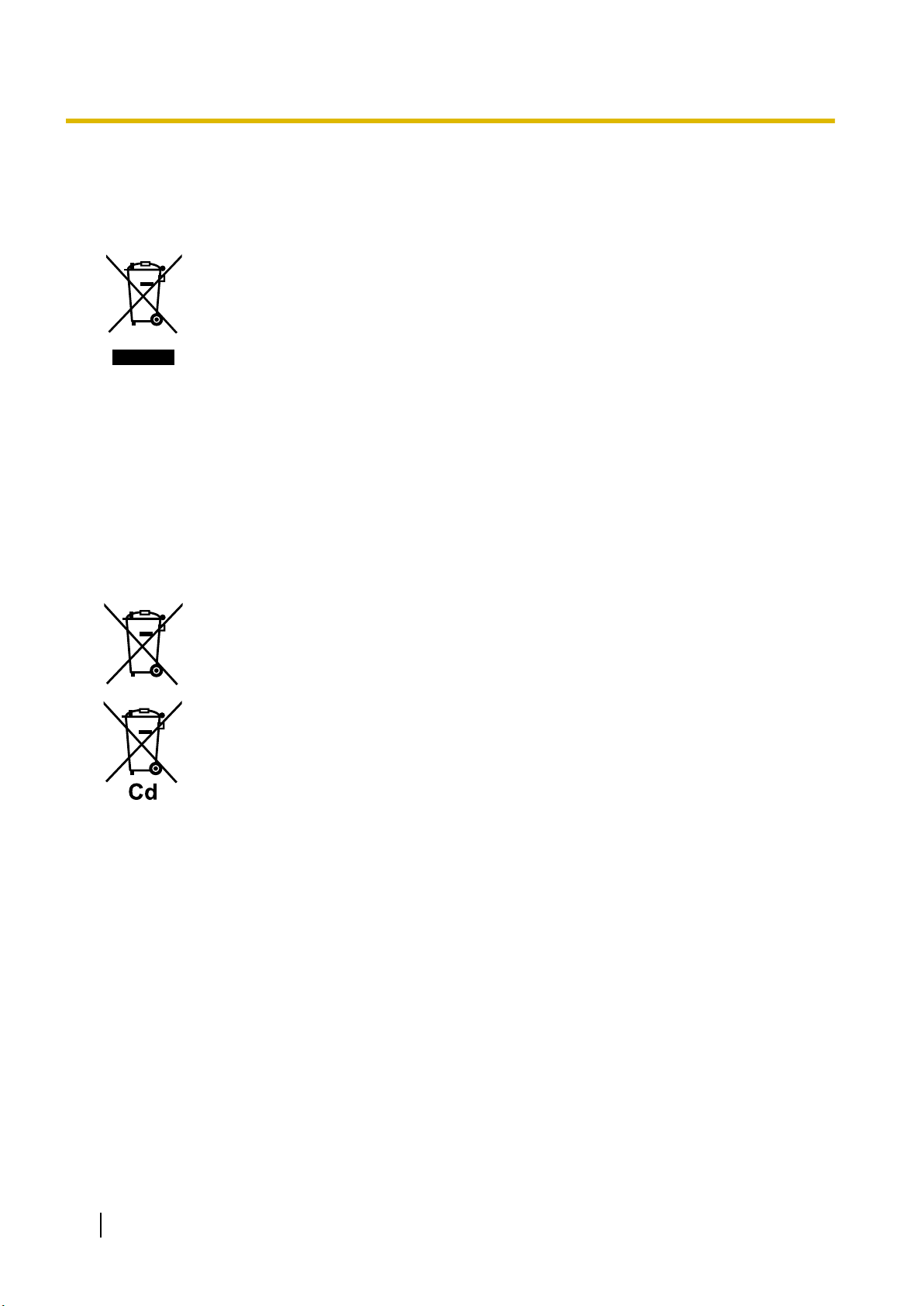
For users in the European Union only
Information for Users on Collection and Disposal of Old Equipment and used Batteries
These symbols on the products, packaging, and/or accompanying documents
mean that used electrical and electronic products and batteries should not be
mixed with general household waste.
For proper treatment, recovery and recycling of old products and used batteries,
please take them to applicable collection points, in accordance with your national
legislation and the Directives 2002/96/EC and 2006/66/EC.
By disposing of these products and batteries correctly, you will help to save
valuable resources and prevent any potential negative effects on human health
and the environment which could otherwise arise from inappropriate waste
handling.
For more information about collection and recycling of old products and batteries,
please contact your local municipality, your waste disposal service or the point of
sale where you purchased the items.
Penalties may be applicable for incorrect disposal of this waste, in accordance
with national legislation.
For business users in the European Union
If you wish to discard electrical and electronic equipment, please contact your
dealer or supplier for further information.
Information on Disposal in other Countries outside the European Union
These symbols are only valid in the European Union. If you wish to discard these
items, please contact your local authorities or dealer and ask for the correct
method of disposal.
Note for the battery symbol (bottom two symbol examples):
This symbol might be used in combination with a chemical symbol. In this case it
complies with the requirement set by the Directive for the chemical involved.
For users in New Zealand only
This equipment shall not be set to make automatic calls to the Telecom ‘111’ Emergency Service.
•
The grant of a Telepermit for any item of terminal equipment indicates only that Telecom has accepted
•
that the item complies with minimum conditions for connection to its network. It indicates no endorsement of the product by Telecom, nor does it provide any sort of warranty. Above all, it provides no assurance that any item will work correctly in all respects with another item of Telepermitted equipment of a
different make or model, nor does it imply that any product is compatible with all of Telecom’s network
services.
This equipment is not capable, under all operating conditions, of correct operation at the higher speeds
•
for which it is designed. Telecom will accept no responsibility should difficulties arise in such circumstances.
Some parameters required for compliance with Telecom’s Telepermit requirements are dependent on
•
the equipment (PBX) associated with this modem. In order to operate within the limits for compliance
with Telecom’s Specifications, the associated PBX equipment shall be set to ensure that modem calls
are answered between 3 and 30 seconds of receipt of ringing.
Using the toll services of a company other than Telecom:
•
16
Not ice for u sers in C aliforn ia
This product contains a CR coin cell lithium battery that
contains perchlorate material special handling may
apply.
See www.dtsc.ca.gov/hazardouswaste/perchlorate
1.3 Precautions
If the PBX is set up to use the toll services of a company other than Telecom, the telephone numbers
dialled from the Caller Display listings within the PBX will be directed through the toll services of the other company because the telephone numbers include the toll access digit and area code digit. A toll
charge may be incurred. Please check with the toll carrier concerned.
APPLICABLE ONLY TO TELECOM CUSTOMERS WHO HAVE AUTOMATIC ACCESS TO OTHER
•
CARRIERS FOR TOLL CALLS
When calling back a number from the Caller ID list, all numbers prefixed with "0 + AREA CODE" will be
automatically forwarded to your toll carrier. This includes numbers in your local calling area. The zero +
area code should either be removed when calling back local numbers, or check with your toll carrier that
a charge will not be levied.
All persons using this device for recording telephone conversations shall comply with New Zealand law.
•
This requires that at least one party to the conversation is to be aware that it is being recorded. In addition, the principles enumerated in the Privacy Act 1993 shall be complied with in respect to the nature of
the personal information collected, the purpose for its collection, how it is used, and what is disclosed to
any other party.
The SLT ports are not specifically designed for 3-wire-connected equipment. 3-wire-connected equip-
•
ment might not respond to incoming ringing when attached to these ports.
For users in Australia only
No External TRC Terminal is provided due to an Internal Link between PE and TRC.
•
For users in Taiwan only
Lithium batteries can be found in the circuit boards of the mother board and optional service cards of the
•
PBX.
Notice
Regarding removing or replacing a battery in the circuit board, consult your dealer.
Note
When disposing of any of the above products, all batteries must be removed. Follow the applicable
•
laws, regulations, and guidelines in your country/area regarding disposal of batteries.
When replacing a battery, use only the same battery type, or an equivalent recommended by the
•
battery manufacturer.
17

1.3 Precautions
Password Security
CAUTION
To the Administrator or Installer regarding the system password
1. Please provide all system passwords to the customer.
2. To avoid unauthorised access and possible abuse of the PBX, keep the passwords secret, and in-
form the customer of the importance of the passwords, and the possible dangers if they become
known to others.
3. The PBX has default passwords preset. For security, change these passwords the first time that you
programme the PBX.
4. Change the passwords periodically.
5. It is strongly recommended that passwords of 10 numbers or characters be used for maximum pro-
tection against unauthorised access. For a list of numbers and characters that can be used in system passwords, refer to "1.2 Entering Characters" in the Programming Item List.
18

1.4 Data Security
1.4 Data Security
In order to use the PBX safely and correctly, the Security Requirements below must be observed. Failure to
do so may result in:
Loss, leakage, falsification or theft of user information.
•
Illegal use of the PBX by a third party.
•
Interference or suspension of service caused by a third party.
•
What is User Information?
User Information is defined as:
Information sent from the PBX to a PC or a USB memory device, such as system data files.
Requirements
1. Always make backups of data stored on the System memory and/or perform regular system data back-
ups to a USB memory device. Refer to "Maintenance-[2-3]System Control-System Data Backup- ◆System Data Backup" in the Programming Item List.
2. To prevent illegal access from the Internet, activate a Firewall.
3. To avoid unauthorised access and possible abuse of the PBX, we strongly recommend:
a. Keeping the password secret.
b. Selecting a complex, random password that cannot be easily guessed.
c. Changing your password regularly.
4. Perform the following when sending the PBX for repair or handing it over to a third party.
a. Make a backup of data stored on the System memory.
5. When user information is sent from the PBX to a PC or a USB memory device, the confidentiality of that
information becomes the responsibility of the customer. Before disposing of the PC or the USB memory
device, ensure that data cannot be retrieved from it by formatting the hard disk and/or rendering it physically unusable.
1.5 F.C.C. REQUIREMENTS AND RELEVANT INFORMATION
1. Notification to the Telephone Company
This equipment complies with Part 68 of the FCC rules and the requirements adopted by the ACTA. On
the side of this equipment is a label that contains, among other information, a product identifier in the
format US: ACJIS04BKX-HTS824. If requested, this number must be provided to the telephone company.
Installation must be performed by a qualified professional installer. If required, provide the telephone
company with the following technical information:
• Telephone numbers to which the system will be connected
• Make: Panasonic
• Model: KX-HTS824
• Certification No.: found on the side of the unit
• Ringer Equivalence No.: 0.4B
• Facility Interface Code: 02LS2
• Service Order Code: 9.0F
• Required Network Interface Jack: RJ11C
19

1.5 F.C.C. REQUIREMENTS AND RELEVANT INFORMATION
2. Ringer Equivalence Number (REN)
The REN is used to determine the number of devices that may be connected to a telephone line. Excessive RENs on a telephone line may result in the devices not ringing in response to an incoming call. In
most but not all areas, the sum of RENs should not exceed five (5.0). To be certain of the number of
devices that may be connected to a line, as determined by the total RENs, contact the local telephone
company.
The REN for this product is part of the product identifier that has the format US: ACJIS04BKX-HTS824.
The digits represented by 04 are the REN without a decimal point (e.g., 04 is a REN of 0.4). For earlier
products, the REN is separately shown on the label.
3. Incidence of Harm to the Telephone Lines
If this equipment causes harm to the telephone network, the telephone company will notify you in advance that temporary discontinuance of service may be required. But if advance notice isn't practical,
the telephone company will notify the customer as soon as possible. Also, you will be advised of your
right to file a complaint with the FCC if you believe it is necessary.
4. Changes in Telephone Company Communications Facilities, Equipment, Operations and Proce-
dures
The telephone company may make changes in its facilities, equipment, operations or procedures that
could affect the operation of the equipment. If this happens the telephone company will provide advance
notice in order for you to make necessary modifications to maintain uninterrupted service.
5. Trouble with this equipment
If trouble is experienced with this equipment, for repair or warranty information, please see the attached
warranty, which includes the Service Center Directory. If the equipment is causing harm to the telephone
network, the telephone company may request that you disconnect the equipment until the problem is resolved.
6. Connection to Party Line
Connection to party line service is subject to state tariffs. Contact the state public utility commission,
public service commission or corporation commission for information.
7. Combined Use with Alarm Equipment
If your home has specially wired alarm equipment connected to the telephone line, ensure the installation of this equipment does not disable your alarm equipment. If you have questions about what will disable alarm equipment, consult your telephone company or a qualified installer.
Note
This equipment has been tested and found to comply with the limits for a Class B digital device, pursuant to Part 15 of the FCC Rules. These limits are designed to provide reasonable protection against
harmful interference in a residential installation. This equipment generates, uses, and can radiate radio
frequency energy and, if not installed and used in accordance with the instructions, may cause harmful
interference to radio communications. However, there is no guarantee that interference will not occur in
a particular installation. If this equipment does cause harmful interference to radio or television reception, which can be determined by turning the equipment off and on, the user is encouraged to try to correct the interference by one or more of the following measures:
Reorient or relocate the receiving antenna.
•
Increase the separation between the equipment and receiver.
•
Connect the equipment into an outlet on a circuit different from that to which the receiver is connec-
•
ted.
Consult the dealer or an experienced radio/TV technician for help.
•
CAUTION
Any changes or modifications not expressly approved by the party responsible for compliance could
•
void the user's authority to operate this device.
When programming emergency numbers and/or making test calls to emergency numbers:
•
20

1.5 F.C.C. REQUIREMENTS AND RELEVANT INFORMATION
1. Remain on the line and briefly explain to the dispatcher the reason for the call before hanging
up.
2. Perform such activities in the off-peak hours, such as early morning hours or late evenings.
The software contained in the ARS and TRS features to allow user access to the network must be
•
upgraded to recognize newly established network area codes and exchange codes as they are
placed into service. Failure to upgrade the premises PBXs or peripheral equipment to recognize the
new codes as they are established will restrict the customer and the customer's employees from
gaining access to the network and to these codes.
KEEP THE SOFTWARE UP-TO-DATE WITH THE LATEST DATA.
RF Exposure Warning:
This product complies with FCC radiation exposure limits set forth for an uncontrolled environment. To comply with FCC RF exposure requirements, this product must be installed and operated in accordance with the
provided instructions. The installed unit requires a minimum 20 cm (8 inches) of spacing between the PBX
and a person’s body. This product must not be co-located or operated in conjunction with any other antennas or transmitters.
21

1.5 F.C.C. REQUIREMENTS AND RELEVANT INFORMATION
22

Section 2
System Outline
This section provides general information on the PBX,
including the system capacity and specifications.
23
2.1 Basic System Construction
2.1 Basic System Construction
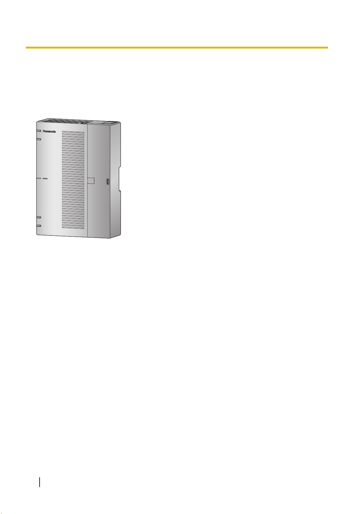
2.1.1 System Configurations
Main Unit
The main unit contains a mother board for controlling PBX functions.
24
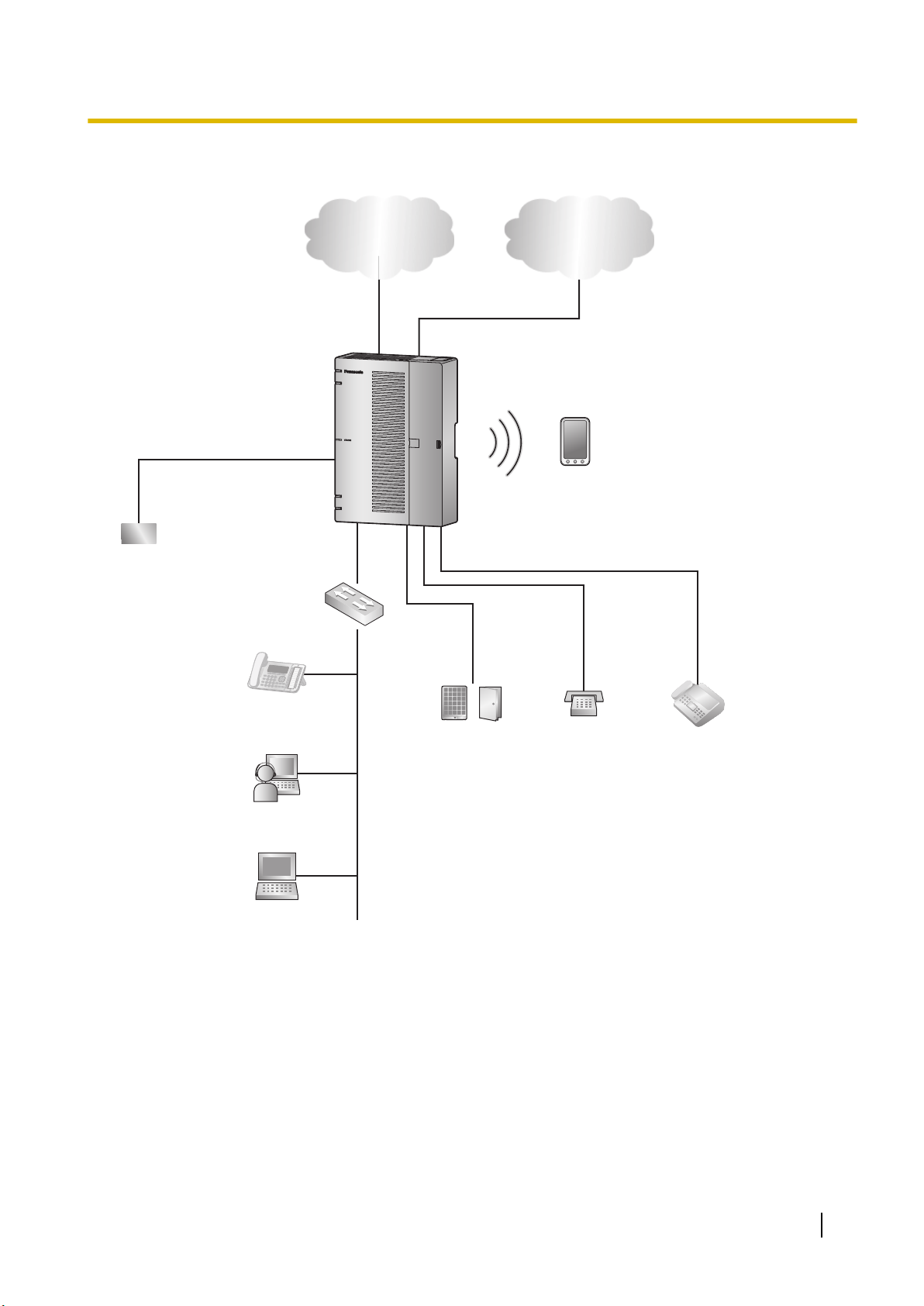
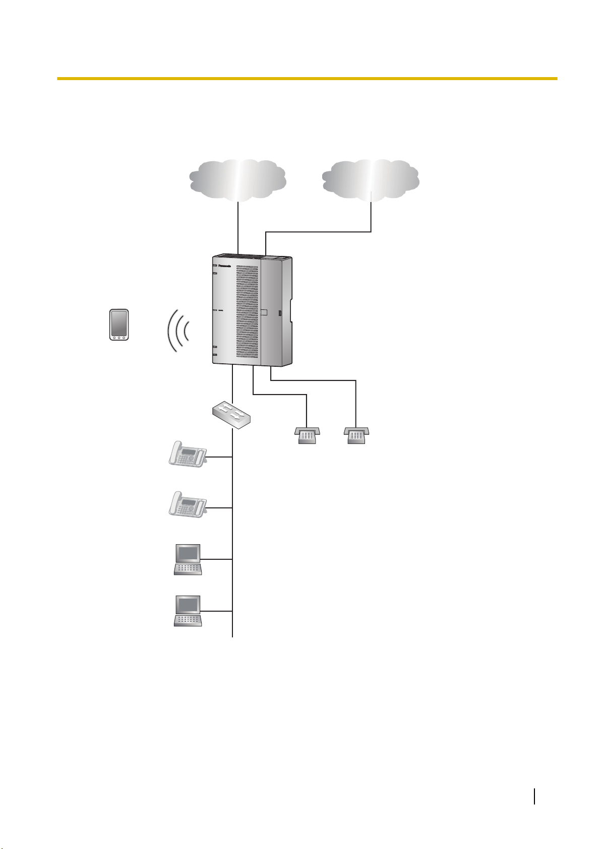
2.1.2 System Connection Diagram
WAN
PBX
Switching Hub
LAN
Doorphone &
Door Opener
SLT
Fax Machine
Battery
PC
IP Network Analogue Trunk
SIP Phone
*1
Smartphone
(Softphone)
IP Softphone
2.1.2 System Connection Diagram
*1
SIP Phone: Panasonic SIP Phone is included
25
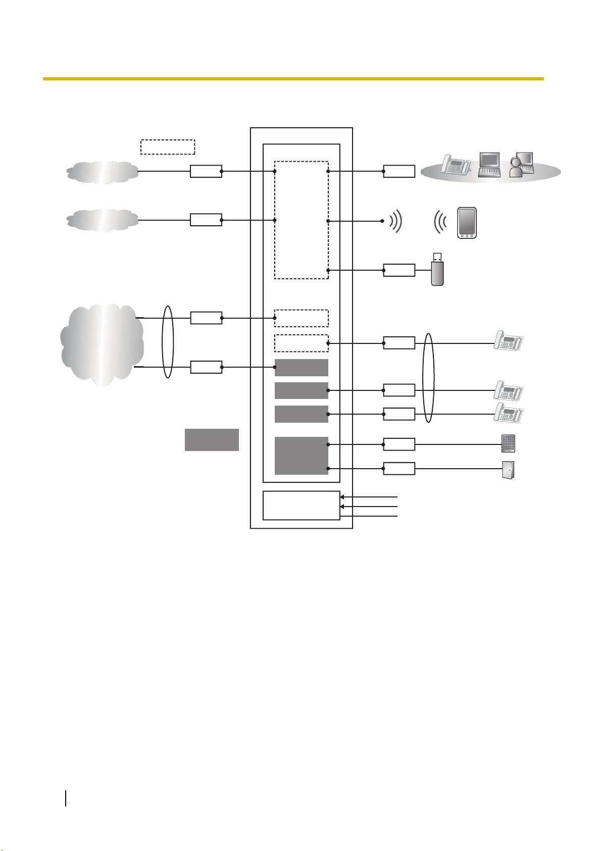
RJ11
RJ11
RJ45
RJ45
RJ45
USB1
PSTN
8 ports
24 ports
AC Input
DC Battery input
FG
8 ports
Main
PBX
LCOT4+SLC8
CPU
LCOT4
SLC8
AC/DC Unit
L2SW
Wi-Fi
DSP
RJ11
RJ11
RJ11
RJ11
SIP Trunk
Internet
LCOT4
SLC8
SLC8
DPH2
Option
card
2.1.3 Block Diagram
2.1.3 Block Diagram
26
Router
PBX
IP Network Analogue Trunk
SLT SLT
Smartphone
(Softphone)
SIP Phone
LAN
WAN
SIP Phone
PC
PC
Switching Hub
2.1.4 Typical Network Setting Example
2.1.4 Typical Network Setting Example
An example of typical network connection is shown below.
1. When installing in a new office or an office where there is no network infrastructure.
Notice
• Refer to the following when the internal DHCP server will be used.
For details about DHCP server settings, refer to "Network Configuration-[4-2]LAN Settings-
◆DHCP Mode" in the Programming Item List.
27
IP Network Analogue Trunk
Router
SLT SLT
PBX
Smartphone
(Softphone)
SIP Phone
SIP Phone
DHCP Server
PC
PC
WAN
LAN
2.1.4 Typical Network Setting Example
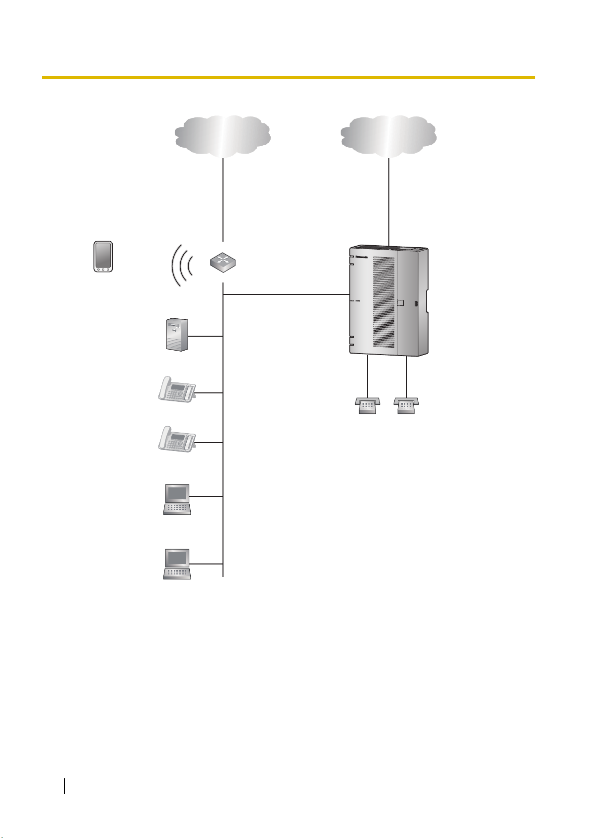
2. When installing in an office that already has a network infrastructure.
Note
– Dynamic Host Configuration Protocol (DHCP) Server
Notice
Description
The PBX has a built-in DHCP server. When the DHCP server is enabled, the PBX will automatically assign IP addresses to other devices on the network.
Using a DHCP server simplifies network management by removing the need to assign IP addresses to devices manually.
28
• If an external DHCP server is in use, the DHCP Server feature of the PBX must be disabled.

2.1.4 Typical Network Setting Example
For details about DHCP server settings, refer to "Network Configuration-[4-2]LAN Settings-
◆DHCP Mode" in the Programming Item List.
29
Switching Hub
IP Network Analogue Trunk
Router
WAN
LAN
SLT SLT
PBX
Smartphone
(Softphone)
SIP Phone SIP Phone
PC
PC
2.1.4 Typical Network Setting Example
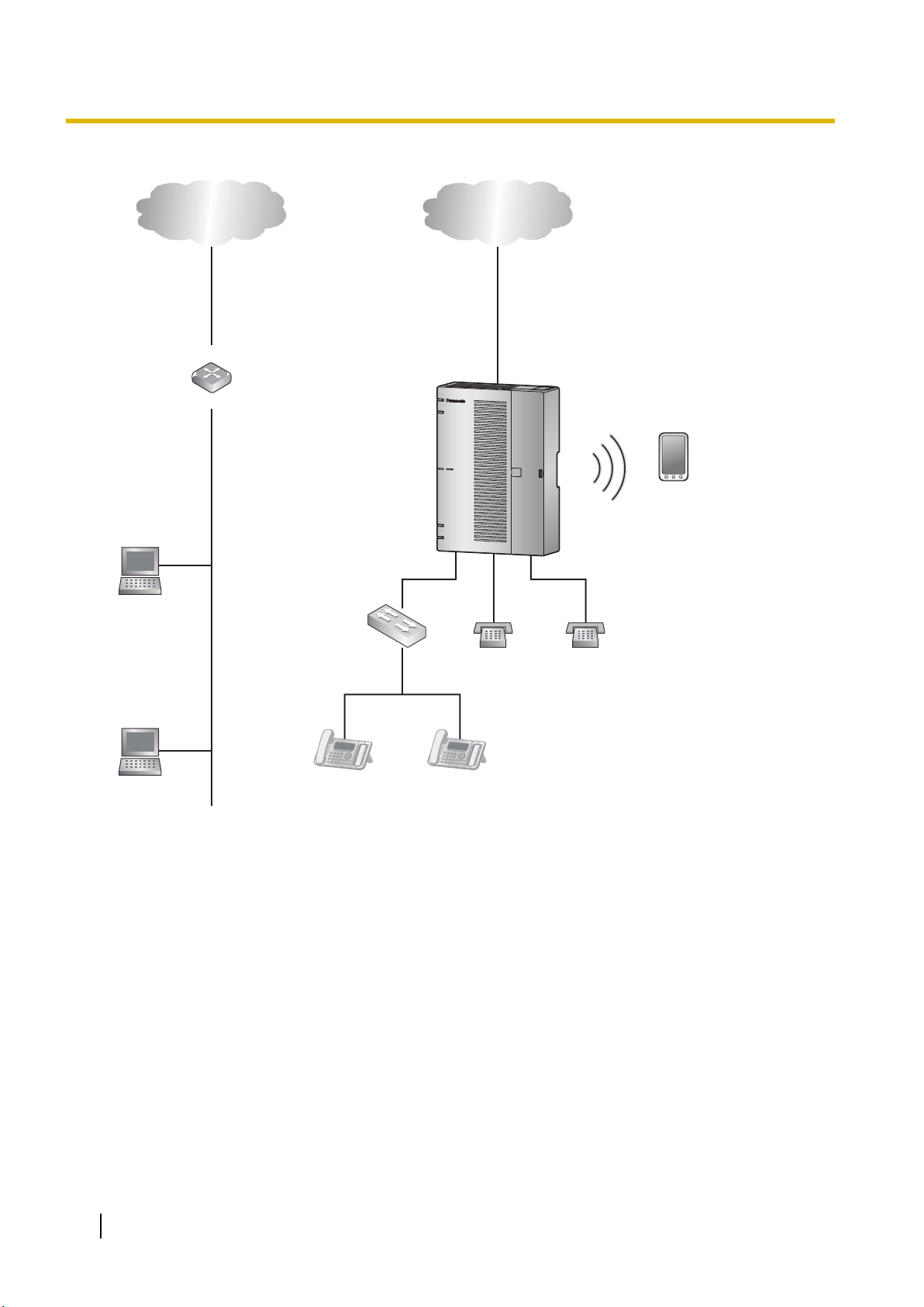
3. When installing the PBX without connecting it to an existing network.
Notice
• Refer to the following when the internal DHCP server will be used.
For details about DHCP server settings, refer to "Network Configuration-[4-2]LAN Settings-
◆DHCP Mode" in the Programming Item List.
30
 Loading...