

Panasonic 96NKX-HNC600 Test Report
Report No. 258223-5
Test Report
Product
Name and address of the
applicant
Name and address of the
manufacturer
Model
Rating
Trademark
Serial number
Additional information
Tested according to
Order number
UPCS Transceiver in Outdoor Camera
Panasonic Corporation of North America
Panasonic System Networks Co., Ltd.
1-62, 4-chome, Minoshima, Hakata-ku
Fukuoka 812-8531, Japan
KX-HNC600
120 V AC (Mains)
Panasonic
/
DECT 6.0
FCC Part 15, subpart D
Isochronous UPCS Device, 1920 – 1930 MHz
Industry Canada RSS 213, Issue 2
2 GHz License-exempt Personal Communications Service Devices (LE-PCS)
258223
Tested in period
Issue date
Name and address of the
testing laboratory
2014.05.07 to 2014.05.14
2014.05.26
FCC No: 994405
Instituttveien 6
Kjeller, Norway
IC OATS: 2040D-1
TEL: (+47) 22 96 03 30
FAX: (+47) 22 96 05 50
This report shall not be reproduced except in full without the written approval of Nemko. Opinions and interpretations
expressed within this report are not part of the current accreditation. This report was originally distributed electronically
with digital signatures. For more information contact Nemko.
Prepared by [Frode Sveinsen] Approved by [G.Suhanthakumar]
Template version: B
Nemko Norway
Nemko AS, Instituttveien 6, P.O. Box 96 Kjeller, 2007 Kjeller, Norway
TEL
+47 22 96 03 30
ENTERPRISE NUMBER
FAX
+47 22 96 05 50
NO974404532
EMAIL
info@nemko.com
nemko.com/no

FCC ID: ACJ96NKX-HNC600
C
ONTENTS
1
INFORMATION ................................................................................................................................. 3
1.1 Tested Item........................................................................................................................................ 3
1.2 Description of Tested Device ............................................................................................................. 3
1.3 Exposure Evaluation .......................................................................................................................... 3
1.4 Test Environment .............................................................................................................................. 4
1.5 Test Engineer(s) ................................................................................................................................ 4
1.6 Test Equipment ................................................................................................................................. 4
1.7 Other Comments ............................................................................................................................... 4
2
TEST REPORT SUMMARY .............................................................................................................. 5
2.1 General .............................................................................................................................................. 5
2.2 Test Summary ................................................................................................................................... 6
3
TEST RESULTS ................................................................................................................................ 7
3.1 Power Line Conducted Emissions ..................................................................................................... 7
3.2 Coordination with fixed microwave .................................................................................................. 10
3.3 Digital Modulation Techniques ........................................................................................................ 10
3.4 Labeling Requirements ................................................................................................................... 10
3.5 Antenna Requirement...................................................................................................................... 11
3.6 Channel Frequencies ...................................................................................................................... 11
3.7 Automatic Discontinuation of Transmission .................................................................................... 12
3.8 Peak Power Output ......................................................................................................................... 13
3.9 Emission Bandwidth B ..................................................................................................................... 16
3.10 Power Spectral Density ................................................................................................................... 19
3.11 In-Band Unwanted Emissions, Conducted ...................................................................................... 22
3.12 Out-of-band Emissions, Conducted................................................................................................. 24
3.13 Carrier Frequency Stability .............................................................................................................. 30
3.14 Frame Repetition Stability ............................................................................................................... 31
3.15 Frame Period and Jitter ................................................................................................................... 31
3.16 Monitoring Threshold, Least Interfered Channel ............................................................................. 33
3.17 Threshold Monitoring Bandwidth ..................................................................................................... 35
3.18 Reaction Time and Monitoring Interval ............................................................................................ 36
3.19 Time and Spectrum Window Access Procedure ............................................................................. 38
3.20 Acknowledgements and Transmission Duration ............................................................................. 39
3.21 Dual Access Criteria Check ............................................................................................................. 41
3.22 Alternative Monitoring Interval ......................................................................................................... 45
4
TEST SETUPS ................................................................................................................................ 46
4.1 Frequency Measurements ............................................................................................................... 46
4.2 Timing Measurements ..................................................................................................................... 46
4.3 Conducted Emission Test................................................................................................................ 46
4.4 Power Line Conducted Emissions Test ........................................................................................... 46
4.5 Monitoring Tests .............................................................................................................................. 47
5
TEST EQUIPMENT USED .............................................................................................................. 48
TEST REPORT
FCC part 15D
Report no.: 258223-5
Nemko Norway, Instituttveien 6, Kjeller, Norway Page 2 (48)
Report no.: 258223-5
FCC ID: ACJ96NKX-HNC600
1 INFORMATION
1.1 Tested Item
Name : Panasonic
Model name : KX-HNC600
FCC ID : ACJ96NKX-HNC600
Industry Canada ID : 216A-KXHNC600
Serial number : /
Hardware identity and/or version: PNLB2371xx
Software identity and/or version : SW401
Tested to IC Radio Standard (RSS) : RSS-213 Issue 2, RSS-GEN Issue 3
Test Site IC Reg. Number : IC 2040D-1
Frequency Range : 1921.536 – 1928.448 MHz
Number of Channels : 5 RF Channels, 5x12 = 60 TDMA Duplex Channels
Type of Modulation : Digital (Gaussian Frequency Shift Keying)
Conducted Output Power : 62 mW (Peak)
Antenna Connector : None
Number of Antennas : 1
Antenna Diversity Supported : No
Power Supply : AC Adaptor Model: PNLV236
TEST REPORT
FCC part 15D
1.2 Description of Tested Device
The EUT is an Indoor Camera with DECT Transmitter and is an initiating device as described in ANSI C63.17
and is designed to operate together with a DECT fixed part (i.e. a base station), which is the responding
device.
1.3 Exposure Evaluation
The EUT is a fixed device and the user manual contains a statement that it should be installed at least 20cm
away from any persons.
Nemko Norway, Instituttveien 6, Kjeller, Norway Page 3 (48)

1.4 Test Environment
TEST REPORT
FCC part 15D
Report no.: 258223-5
FCC ID: ACJ96NKX-HNC600
Temperature:
20.7 – 21.8 °C
Relative humidity: 36 - 43 %
Normal test voltage: 120 V AC (with AC Adaptor PNLV236)
The values are the limit registered during the test period.
1.5 Test Engineer(s)
Frode Sveinsen
Thanh Tran
1.6 Test Equipment
See list of test equipment in clause 6.
1.7 Other Comments
The Monitoring and Time and Spectrum Window Access tests were performed with Test Set-Up 6 (Ref.
clause 5). A clock signal from the companion device was used to synchronize the Pulse Pattern Generator
and the Spectrum Analyzer to the start of the DECT time window. The EUT was limited by administrative
commands to operate on only two frequency carriers. For the tests where the EUT was required to operate
on only one frequency carrier, one carrier was blocked by applying a CW interfering signal from RF
Generator 3. The Pulse Pattern Generator was used to apply time synchronized interference to time windows
where this was required.
This EUT supports Least Interfered Channel procedure (LIC), the Monitoring and Time and Spectrum
Window Access tests were conducted as specified for EUTs that support LIC procedure.
All tests except Power-Line Conducted Emissions were performed in conducted mode with a temporary
antenna connector.
Nemko Norway, Instituttveien 6, Kjeller, Norway Page 4 (48)

TEST REPORT
FCC part 15D
Report no.: 258223-5
FCC ID: ACJ96NKX-HNC600
2 TEST REPORT SUMMARY
2.1 General
All measurements are traceable to national standards.
The tests were conducted on a sample of the equipment for the purpose of demonstrating compliance with
FCC CFR47 Part 15D for Isochronous UPCS Devices and Industry Canada RSS-213 Issue 2 / RSS-GEN
Issue 3.
All tests were conducted is accordance with ANSI C63.4-2009 and ANSI C63.17-2006. Antenna Gain tests
were made in a 3m fully-anechoic chamber.
A description of the test facility is on file with the FCC and Industry Canada.
New Submission Production Unit
Class II Permissive Change Pre-production Unit
PUB
Equipment Code Family Listing
THIS TEST REPORT APPLIES ONLY TO THE ITEM(S) AND CONFIGURATIONS TESTED.
Deviations from, additions to, or exclusions from the test specifications are described in “Summary of Test Data”.
Nemko Group authorizes the above named company to reproduce this report provided it is reproduced in its entirety and for use by the
company’s employees only. Any reproduction of parts of this report requires approval in writing from Nemko Group.
Any use which a third party makes of this report, or any reliance on or decisions to be made based on it, are the responsibility of such
third parties. Nemko Group accepts no responsibility for damages suffered by any third party as a result of decisions made or actions
based on this report.
Nemko Norway, Instituttveien 6, Kjeller, Norway Page 5 (48)
2.2 Test Summary
TEST REPORT
FCC part 15D
Report no.: 258223-5
FCC ID: ACJ96NKX-HNC600
Name of test FCC CFR 47
Paragraph #
Power Line Conducted Emission 15.107(a)
15.207(a)
IC RSS-213
Paragraph #
6.3
RSS-GEN 7.2.2
Verdict
Complies
Coordination with fixed microwave 15.307(b) N/A Complies
Digital Modulation Techniques 15.319(b) 6.1 Complies
Labeling requirements 15.19(a)(3) 3
Complies
RSS-GEN 5.2
Antenna Requirement 15.317, 15.203 RSS-GEN 7.1.2 Complies
Channel Frequencies 15.303 1 Complies
Automatic discontinuation of transmission 15.319(f) 4.3.4(a) Complies
Emission Bandwidth 15.323(a) 6.4 Complies
In-band emissions 15.323(d) 6.7.2 Complies
Out-of-band emissions 15.323(d) 6.7.1 Complies
Output Power and Antenna Gain 15.319(c)(e),
6.5 and 4.1(e) Complies
15.31(e)
Power Spectral Density 15.319(d) 4.3.2.1 Complies
Carrier frequency stability 15.323(f) 6.2 Complies
Frame repetition stability 15.323(e) 4.3.4(c) Complies
Frame period and jitter 15.323(e) 4.3.4(c) Complies
Monitoring threshold, Least interfered channel 15.323(c)(2);(5); (9) 4.3.4(b) Complies
Monitoring of intended transmit window and
15.323(c)(1) 4.3.4(b) Complies
maximum reaction time
Threshold monitoring bandwidth 15.323(c)(7) 4.3.4(b) Complies
Reaction time and monitoring interval 15.323(c)(1);(5); (7) 4.3.4(b) Complies
Access criteria test interval 15.323(c)(4);(6) 4.3.4(b) N/A1
Access Criteria functional test 15.323(c)(4);(6) 4.3.4(b) N/A1
Acknowledgements 15.323(c)(4) 4.3.4(b) Complies
Transmission duration 15.323(c)(3) 4.3.4(b) Complies
Dual access criteria 15.323(c)(10) 4.3.4(b) Complies
Alterative monitoring interval 15.323(c)(10);(11) 4.3.4(b) N/A2
Spurious Emissions (Radiated) 15.319(g)
15.109(a)
4.3.3
RSS-GEN 7.2.3
N/A3
15.209(a)
1
Only applies for equipment that transmits unacknowledged control and signaling information
2
The client declares that the tested equipment does not implement this provision
3
Not required if the Conducted Out-of-Band Emissions test is Passed
Nemko Norway, Instituttveien 6, Kjeller, Norway Page 6 (48)

Report no.: 258223-5
FCC ID: ACJ96NKX-HNC600
3 TEST RESULTS
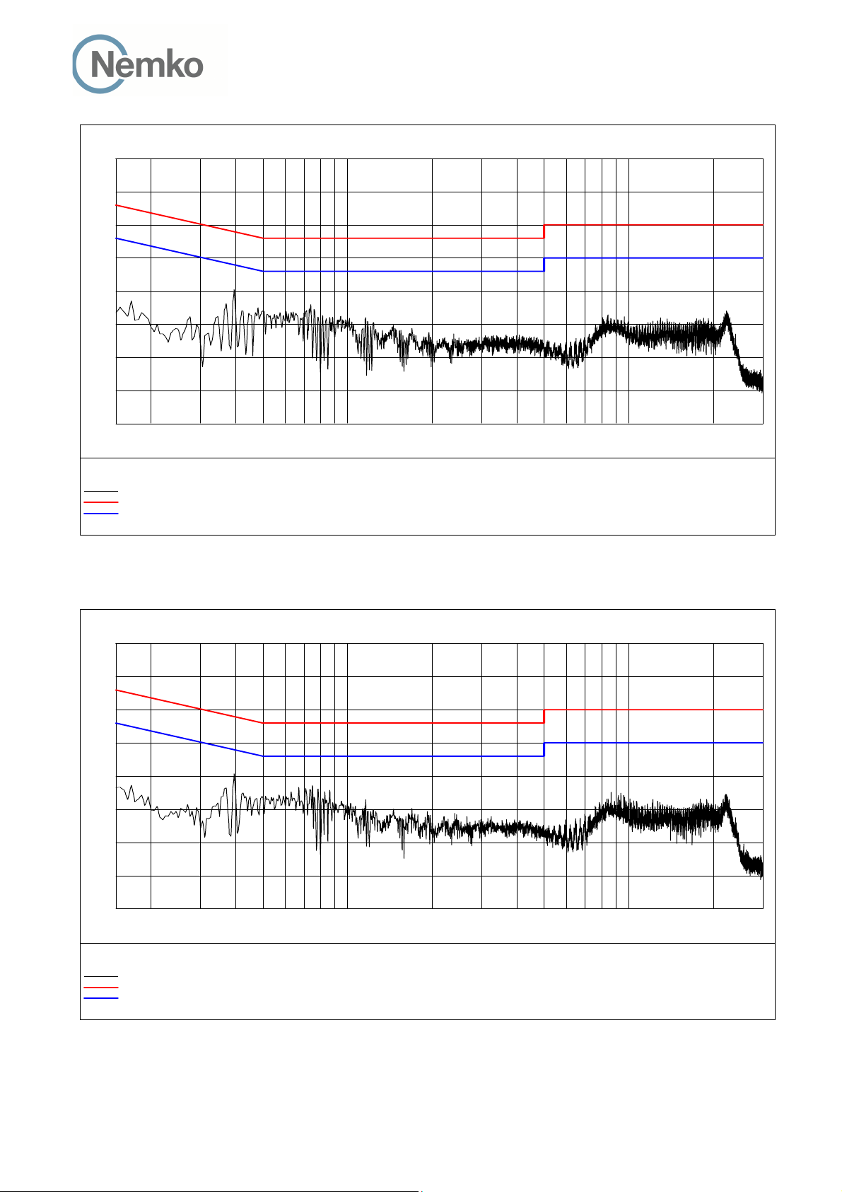
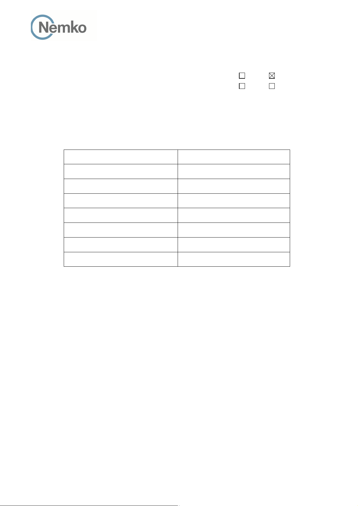
3.1 Power Line Conducted Emissions
Para. No.: 15.207 (a)
Test Performed By: Thanh Tran Date of Test: 13-May-2014
Measurement procedure: ANSI C63.4-2009 using 50 µH/50 ohms LISN.
Test Results: Complies
Measurement Data: See attached graph, (Peak detector).
Highest measured value (L1 and N):
(Plots show maximum of Phase L1 and N)
TEST REPORT
FCC part 15D
Nemko Norway, Instituttveien 6, Kjeller, Norway Page 7 (48)
TEST REPORT
FCC part 15D
Report no.: 258223-5
FCC ID: ACJ96NKX-HNC600
Standby Mode with PNLV236 Adaptor, 120V 60Hz:
Frequency Level Af Limit Margin Det Position Verdict
[MHz] [dBuV] [dB] [dBuV] [dB] [Pass/Fail]
0.395000 39.00 10.20 58.00 19.00 QP L1 Pass
0.370000 29.00 10.20 48.50 19.50 AV L1 Pass
0.395000 36.50 10.20 48.00 11.50 AV L1 Pass
0.445000 20.20 10.20 47.00 26.80 AV L1 Pass
0.480000 11.20 10.20 46.30 35.10 AV L1 Pass
0.740000 22.10 10.20 46.00 23.90 AV L1 Pass
0.760000 19.40 10.20 46.00 26.60 AV L1 Pass
0.785000 17.40 10.20 46.00 28.60 AV N Pass
0.815000 19.90 10.20 46.00 26.10 AV N Pass
0.840000 18.90 10.20 46.00 27.10 AV N Pass
0.945000 15.10 10.20 46.00 30.90 AV N Pass
1.155000 17.10 10.20 46.00 28.90 AV N Pass
1.180000 15.00 10.20 46.00 31.00 AV N Pass
1.240000 11.70 10.20 46.00 34.30 AV L1 Pass
1.455000 13.90 10.20 46.00 32.10 AV L1 Pass
22.325000 14.30 11.30 50.00 35.70 AV N Pass
Transmit Mode with PNLV236 Adaptor, 120V 60Hz:
Frequency Level Af Limit Margin Det Position Verdict
[MHz] [dBuV] [dB] [dBuV] [dB] [Pass/Fail]
0.395000 39.20 10.20 58.00 18.80 QP L1 Pass
0.750000 30.30 10.20 56.00 25.70 QP N Pass
0.170000 16.00 10.10 55.00 39.00 AV L1 Pass
0.370000 28.40 10.20 48.50 20.10 AV L1 Pass
0.395000 36.50 10.20 48.00 11.50 AV L1 Pass
0.570000 17.30 10.20 46.00 28.70 AV N Pass
0.750000 9.00 10.20 46.00 37.00 AV N Pass
0.785000 18.00 10.20 46.00 28.00 AV N Pass
0.830000 6.90 10.20 46.00 39.10 AV N Pass
0.865000 17.00 10.20 46.00 29.00 AV N Pass
0.950000 12.00 10.20 46.00 34.00 AV N Pass
1.695000 10.70 10.20 46.00 35.30 AV L1 Pass
1.925000 12.20 10.20 46.00 33.80 AV L1 Pass
8.670000 15.10 10.60 50.00 34.90 AV L1 Pass
12.200000 13.00 10.70 50.00 37.00 AV L1 Pass
18.000000 11.30 11.00 50.00 38.70 AV L1 Pass
22.205000 15.20 11.30 50.00 34.80 AV N Pass
Nemko Norway, Instituttveien 6, Kjeller, Norway Page 8 (48)
Level [dBµV]
80
70
60
50
TEST REPORT
FCC part 15D
Report no.: 258223-5
FCC ID: ACJ96NKX-HNC600
40
30
20
10
0
150k 300k 500k 1M 2M 3M 5M 7M 10M 30M
x MES 258223N_Qp
+ MES 258223N_Av
MES 258223N
LIM EN 55022 V QP
LIM EN 55022 V AV
x
+
+
+
+
+
+
+
+
+
+
+
+
+
+
Frequency [Hz]
Standby Mode with PNLV236 Adaptor, 120V 60Hz
Level [dBµV]
80
70
+
60
50
40
30
20
+
10
0
150k 300k 500k 1M 2M 3M 5M 7M 10M 30M
x MES 258223N_Qp
+ MES 258223N_Av
MES 258223N
LIM EN 55022 V QP
LIM EN 55022 V AV
x
+
+
x
+
+
+
+
+
+
Frequency [Hz]
+
+
+
+
Transmit Mode with PNLV236 Adaptor, 120V 60Hz
+
+
Nemko Norway, Instituttveien 6, Kjeller, Norway Page 9 (48)

TEST REPORT
FCC part 15D
Report no.: 258223-5
FCC ID: ACJ96NKX-HNC600
3.2 Coordination with fixed microwave
The affidavit from UTAM, Inc. is included in the documentation supplied by the applicant:
Yes No
Requirement, FCC 15.307 (b):
Each application for certification of equipment operating under the provisions of this Subpart must be
accompanied by an affidavit from UTAM, Inc. certifying that the applicant is a participating member of UTAM,
Inc. In the event a grantee fails to fulfill the obligations attendant to participation in UTAM, Inc., the
Commission may invoke administrative sanctions as necessary to preclude continued marketing and
installation of devices covered by the grant of certification, including but not limited to revoking certification.
3.3 Digital Modulation Techniques
The EUT uses Multi Carrier / Time Division Multiple Access / Time Division Duplex and Digital GFSK
modulation. For further details see the operational description provided by the applicant.
Requirement, FCC 15.319(b):
All transmissions must use only digital modulation techniques.
3.4 Labeling Requirements
See separate documents showing the label design and the placement of the label on the EUT.
Requirements FCC 15.19
The FCC Identifier shall be displayed on the label, and the device(s) shall bear the following statement in a
conspicuous location on the device or in the user manual if the device is too small:
This device complies with Part 15 of the FCC Rules. Operation is subject to the following two conditions: (1)
this device may not cause harmful interference, and (2) this device must accept any interference received,
including interference that may cause undesired operation.
The label itself shall be of a permanent type, not a paper label, and shall last the lifetime of the equipment.
Nemko Norway, Instituttveien 6, Kjeller, Norway Page 10 (48)
Report no.: 258223-5
FCC ID: ACJ96NKX-HNC600
3.5 Antenna Requirement
Does the EUT have detachable antenna(s)? Yes No
TEST REPORT
FCC part 15D
If detachable, is the antenna connector(s) non-standard?
Yes No
The tested equipment has only integral antennas. The conducted tests were performed on a sample with a
temporary antenna connector.
Requirement: FCC 15.203, 15.204, 15.317.
3.6 Channel Frequencies
UPCS CHANNEL FREQUENCY (MHz)
Upper Band Edge
0 (Highest)
1
2
3
4 (Lowest)
Lower Band Edge
1930.000
1928.448
1926.720
1924.992
1923.264
1921.536
1920.000
Requirement: FCC 15.303
Within 1920 -1930 MHz band for isochronous devices.
Nemko Norway, Instituttveien 6, Kjeller, Norway Page 11 (48)
TEST REPORT
FCC part 15D
Report no.: 258223-5
FCC ID: ACJ96NKX-HNC600
3.7 Automatic Discontinuation of Transmission
Does the EUT transmit Control and Signaling Information? YES NO
TYPE OF EUT : INITIATING DEVICE RESPONDING DEVICE
The following tests simulate the reaction of the EUT in case of either absence of information to transmit or
operational failure after a connection with the companion device is established.
Number Test EUT Reaction Verdict
1 Power removed from EUT C
2 Switch Off EUT N/A
3 Hook-On by EUT N/A
4 Power Removed from Companion Device A
5 Switch Off Companion Device N/A
6 Hook-On by Companion Device N/A
Pass
Pass
Pass
Pass
Pass
Pass
A - Connection breakdown, Cease of all transmissions
B - Connection breakdown, EUT transmits control and signaling information
C - Connection breakdown, Companion Device transmits control and signaling information
N/A - Not Applicable (Neither EUT nor Companion Device have On/Off switch or can perform Hook-On)
Requirements, FCC 15.319(f)
The device shall automatically discontinue transmission in case of either absence of information to transmit
or operational failure. These provisions are not intended to preclude transmission of control and signaling
information or use of repetitive codes used by certain digital technologies to complete frame or burst
intervals.
Nemko Norway, Instituttveien 6, Kjeller, Norway Page 12 (48)
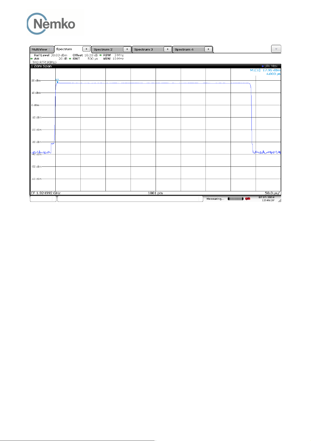
3.8 Peak Power Output
Test Method:
ANSI C63.17, clause 6.1.2.
Test Results: Complies
Measurement Data:
Maximum Conducted Output Power
TEST REPORT
FCC part 15D
Report no.: 258223-5
FCC ID: ACJ96NKX-HNC600
Channel No. Frequency
(MHz)
4
2
0
1921.536 17.6 0.0* 17.6
1924.992 18.0 0.0* 18.0
1928.448 17.8 0.0* 17.8
Maximum
Conducted
Output Power
(dBm)
Maximum
Antenna
Gain
(dBi)
Maximum
Radiated
Output Power
(dBm)
*Antenna gain value is declared by the manufacturer.
Limit:
Conducted: 100 µW x SQRT(B)
where B is the measured Emission Bandwidth in Hz
FCC 15.319(c)(e): 20.76 dBm (119 mW)
RSS-213, Issue 2: 20.51 dBm (113 mW)
The antenna gain is below 3 dBi, no reduction in transmit power is necessary.
Requirements, FCC 15.319(c)(e), RSS-213, Issue 2
Peak transmit power shall not exceed 100 microwatts multiplied by the square root of the emission bandwidth
in Hertz.
The peak transmit power shall be reduced by the amount in decibels that the maximum directional gain of the
antenna exceeds 3 dBi.
Nemko Norway, Instituttveien 6, Kjeller, Norway Page 13 (48)
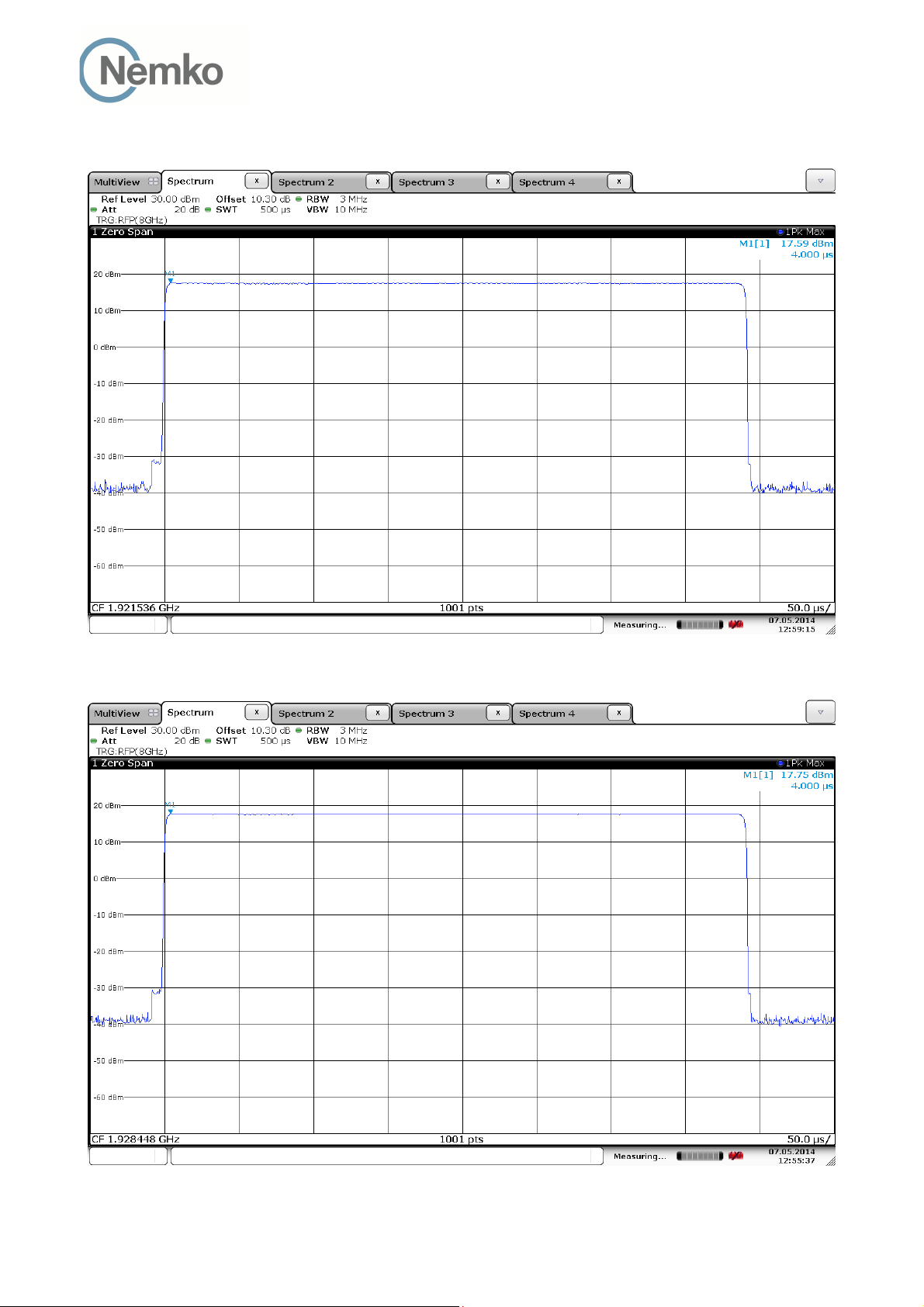
Conducted Peak Output Power
TEST REPORT
FCC part 15D
Report no.: 258223-5
FCC ID: ACJ96NKX-HNC600
Lower Channel
Upper Channel
Nemko Norway, Instituttveien 6, Kjeller, Norway Page 14 (48)
TEST REPORT
FCC part 15D
Report no.: 258223-5
FCC ID: ACJ96NKX-HNC600
Middle Channel
Nemko Norway, Instituttveien 6, Kjeller, Norway Page 15 (48)
 Loading...