

Page 1
AIR TO WATER HEAT PUMP
Installation and Operation Manual
DC INVERTERDC INVERTER
H series Only Heating series
AC series Heating Cooling series
HC series Mutifunctional Heating Cooling Hot water
:
:&
:&
Page 2

Content
Safety Precautions
Transport and storage
General
2
2
2
3
4
11
12
17
19
1
Components
Wired LCD Controller
Error Code
Installation
Electric connection
Test run
Page 3

Safety Precautions
Note!
It is required to read the Safety precautions in detail before
operation. The precautions listed below are all-important for
safety, please obey without fail.
Make sure that the fixed ground wire in the building is securely connected to earth.
Wiring tasks should be carried out by qualified electricians only, in addition, they should check the safety conditions
of power utilization, for example, check if the line capacity is adequate, and check if the power cable is damaged.
Users must not install, repair or relocate the unit.
Improper treatment might lead to the accidents e.g. personal injury caused by fire, electrical shock or unit's fallingoff, and water leakage in the machine. Please contact professional repair and service department of local dealer.
In case the leaked gas is congregated around the machine, there might be the risk of explosion.
The unit shall not be installed at a spot with potential hazard of leakage of inflammable gas.
If the foundation is unstable, the outdoor unit may drop and cause a casualty accident. so this must be validated careful ly.
Make sure that the foundation of installation is stable.
If no electric leakage protection switch is fitted at the beginning of the electric supply, it maybe cause electric shocks or
fires.
Make sure that the electric leakage protection switch is fixed.
Before cleaning, shut off the electric supply of the unit firstly to avoid injuries caused by fan in operation.
Do not rinse the unit by water because the rinsed unit may cause electric shock.
Please observe the follow items when cleaning the unit.
Make sure to shut off the electric supply before maintaining the unit.
Please do not insert fingers or sticks into air outlet or air inlet.
The machine must be transported and stored vertically.
General
If any abnormity occurs in the unit (such as burned taste inside the unit), cut off the power supply immediately,
and contact professional repair and service department of local dealer.
The machine must be transported and stored vertically.
Transport and storage
2
Page 4
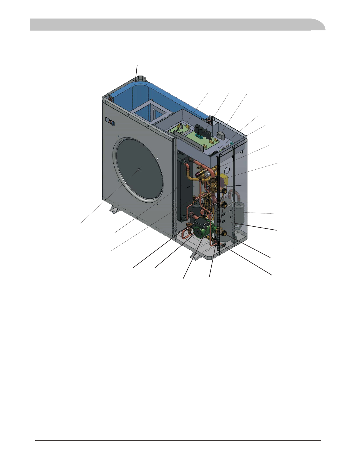
Components
3
Plate heat exchanger
Fan and fan motor
20
Evaporator
Transformer
Terminal blocks
Water system control board
4 way valve
3 way valve
1
2
3
4
5
6
7
8
9
10
12
13
14
15
16
17
18
19
Position
Position
Component
Component
Compressor
Gas liquid isolator
Water inlet
Drain
Needle valve
AH-6,AH-8,AH-11,AH-15DC
2
3
4
1
5
6
7
19
20
8
15
14
9
10
12
13
17
18
16
IPM Module
Main control board AC Outlet
Thermal Expansion Valve
DHW Outlet
Water circulation pump(Optional)
Page 5
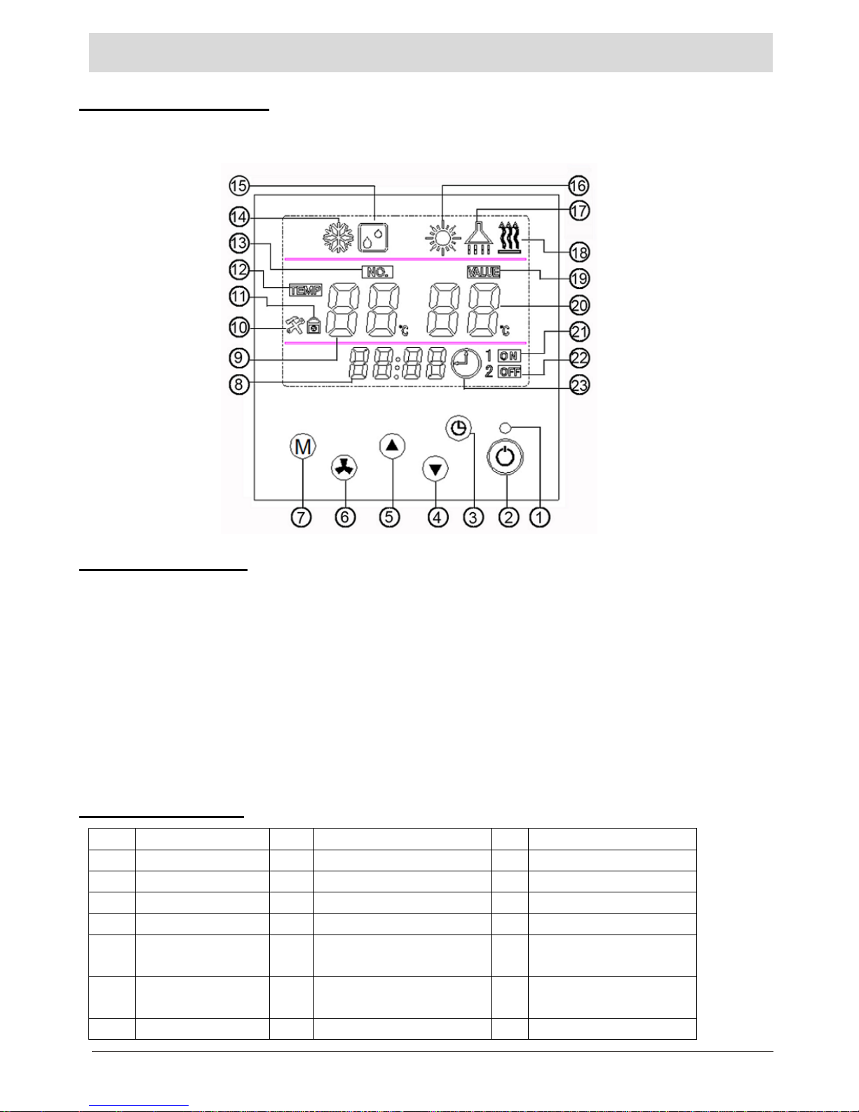
CONTROL PANEL
. 1 Wire controller
Wire controller contains a LCD and 6 operational keys (as show below). It can keep memory when power off
and be a timer.
2. Key functions
(1)Double-colored indicator light: when standby, blue light on; when compressor worked, red light on; when
breakdown happened, red light on. For more details, please check fault code sheet.
(2)Key “on/off” : power on /power off.
(3)Key “time adjusting”: adjust clock or set time.
(4)Key “down”: it’s a combined key to decrease numerical value, continuous press, then continuous decrease;
short press, then decrease by 1.
(5)Key “up”: it’s a combined key also, but opposite to down key. Continuous press, then continuous increase;
short press, then increase by 1.
(6)Key “confirm”: confirm previous operations
(7)Key “mode”: operational mode’s switch. It’s a combined key also.
3. Icon Meaning
NO. Icon meaning NO. Icon meaning NO. Icon meaning
8 Clock display 9 Returned AC Temp. 10 Maintain icon
11 Lock icon 12 Temperature icon (Reserved) 13 Parameter number icon
14 AC Cooling icon 15 Sterilization icon 16 AC heating icon
17 Sanitary hot water icon 18 Water/ground source display 19 Parameter icon
20 Domestic Hot Water
temp
21 Timer on icon 22 Timer off icon
20 Sterilization days dis-
play
21 Sterilization on display 22 Sterilization off display
23 Clock icon
4
Page 6
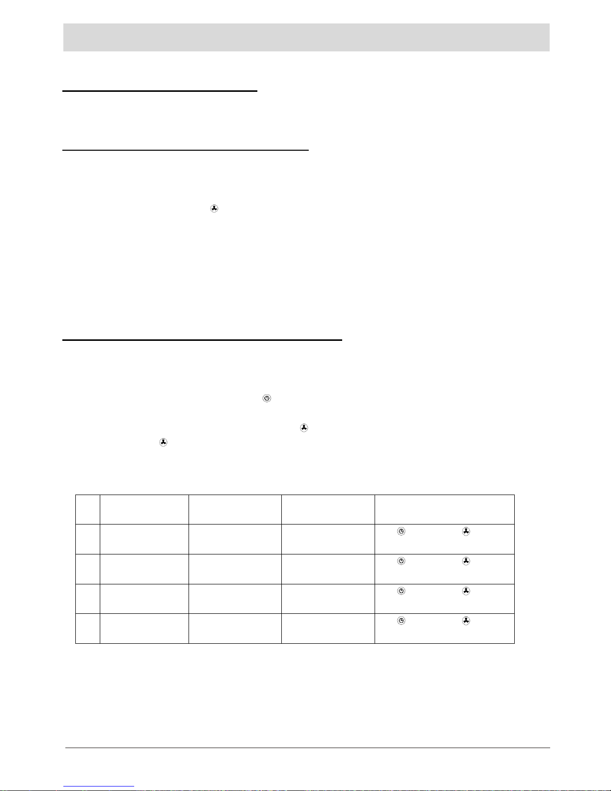
UNIT OPERATION
. 1 Switch the unit On and off
To start the unit, press and hold the On/Off key for one second
To stop the unit, press and hold the On/Off key for one second
. 2 Mode switch(5 modes in total)
A. Under mode standby or On, press the M key repeatly, the following icons will flash by recycling.
AC cooling -> AC heating -> DHW(Domestic hot water)-> AC cooling + DHW ->AC heating +
DHW
When selected a mode, press button to confirm, then the icon will be solid, heat pump will perform as
selected.
B. When in mode AC cooling +DHW or AC heating & DHW, DHW heating will be the priority.
C. When select DHW mode, only hot water system working, no air conditioner working.
D. When select air conditioner mode, only air conditioner system working, no sanitary hot water system working.
E. Sterilization is independent and auto-operated. You can change parameter according to need.
.3 Procedures of setting parameter change
A. When in settled mode, the unit will operate in accordance with the factory default temperature or last modified
temperature.
B. Modification method for settled temperature
In the on / standby mode, press key M and for 3 seconds, the current operating mode light will flash;
by press the M key, you can switch modes in the following order: Cooling / heating / hot water / sterilization;
by pressing key ▲ or ▼to setting value, press key to confirm, then exit and save current changes;
if didn’t press key to confirm, it will exit the parameter modification automatically 15 seconds later. Previous Changes will not be saved.
Detailed settings as follows:
NO. Meaning Settled temperature
range
Default temperature operation for modify settled para-
meters
1 AC cooling returned
water temp
10℃~25℃ 12℃
M+
→M→▲or▼→
2 AC Heating returned
water temp
10℃~55℃ 45℃
M+
→M→▲or▼→
3 sanitary hot water
heating
10℃~60℃(AU) 50℃
M+
→M→▲or▼→
4 Legionella
Anti-bacteria
60℃~70℃ 65℃
M+
→M→▲or▼→
5
Page 7

UNIT OPERATION
C. Time setting procedure for health sterilization
Only in sanitary hot water mode, health sterilization will work. If sanitary hot water mode off, health sterilization
will fail to work.
In on or standby mode, first, press key M and for 3 seconds, second, press key M ,15 icon appears, then
press the ▲ or ▼ to set sterilization temperature, press key to confirm, the number of days will flash and
show the original or default value 7 (that means 7 days), press key ▲ or ▼ to increase or decrease the number
of days at predetermined intervals, the minimum of 7 days, maximum of no more than 99 days, after that ,press
key to confirm. At this time, "ON" character appears, "hour" appears and flashes, show the original setting
or the default value (default value 01 means it will start at 1:00 am), followed by press key ▲ or ▼ to modify
(0-23) ,after that, press key to confirm, then the new time start running. "ON" character disappears, "OFF"
character appears, "minute" value flashes and shows the original or default value (default value is 10), followed
by press key ▲ or ▼to change (minimum is 10, maximum no more than 99), after that press key to confirm
and exit change mode. If didn’t press key to confirm, machine will exit change mode automatically after 15
seconds. But settings did right now will become invalid.
4 Time adjustment
Press key ,time “hour” value will flash, then press key ▲ or ▼,the value will increase or decrease. Press
key and keep, the valve will increase or decrease constantly as you want. After Settle down, please press key
to confirm, then exit from time adjusting mode.
5 Time setting
You can set one time to start and one time to off. And select one time working or cyclic working.
A、 settled time on method:
(1) Press for 3 seconds and come to time setting, will flash as show below.
(2) Press key ▲ or ▼ to modify time value, and press to confirm. This setting only valid for one time. If you
want time setting to work cyclic, please press key after time setting, then press key to confirm.
B、 Timing off method are the same as timing on method.
C、 Please press key
for 3 seconds and come to timing mode, press to cancel time setting.
6
Page 8

. UNIT OPERATION
6 Parameter Checking and setting
Please press key M+▲ for 3 seconds and enter to parameter setting mode as show below.
“01”is parameter code,“78”is parameter values. Other items’ parameters meaning are the same with above
picture showed.
Parameter list:
NO. Name range/meaning default status remark
00 power off auto restart
0:not restart;1:Auto restart
1 check/set
01 hot water temp return differential
2~15℃,minus return differential 2℃
check/set
02 air conditioning return differential
2~15℃,minus return differential 2℃
check/set
03 defrost start temp.
-20~5℃ 0℃
check/set
04 water source anti-freeze temp.
-20~5℃ 2℃
check/set
05 antifreeze exist temp.
-5℃~5℃
5℃
check/set
06 defrost exist temp.
10~35℃ 30℃
check/set
08 Interval between 2 defrosts 15~99 mins 35 check/set
09 ambient temp of DHW backup
electrical heater start
-20~20℃ 0℃
check/set
10 ambient temp of AC backup
electrical heater start
-20~20℃ 0℃
check/set
11 reserved
12 Exhaust gas protection temp.
100~129℃/2
57 check/set
13 reserved
14 function parameter
0:G3 is seasonal switch valve;
1:G3 is solar pre-heat valve;
0 check/set
19 adjust fixed running rate 0~100 HZ 50HZ check/set
20 Run set rate
1:practical running;
0:manual rate running
1 check/set
Note:
Usage of 14. Function parameter: (As per solar application 1)
when this parameter is 1, when air conditioning heating run, it will compare solar water tank temp with air conditioning returned
water temp, when solar water tank temp is 5 or more degree higher than air conditioning returned temp, the 3-way valve G3
electricity supply will be on; when solar water tank temp - air conditioning returned temp is less than 2 centigrade, G3 electricity
supply will be off. This function is to use solar to preheat for room heating and DHW tank water.
When this parameter is 0, G3 is seasonal switch valve, when the heat pump is working for heating, G3 is on, when heat pump is
working for cooling, G3 is off.
Normally use one 3-way valve with 3 wires. 2 wires are always connected with electricity supply and 1 signal wire is connected
with heat pump G3 terminal port to enable function.
7
Page 9

UNIT OPERATION
.7 Machine operational status Checking
Press both key M and ▼ for 3 seconds, then entered machine status form. Show as below.
“C0”is part or parameter NO. , “28” stands for parameter. Parameter 0 means system on, 1 means system off.
For more detail, please check form below.
Press M+ ▼ for 3 seconds to search and check parameters .
NO. Name range/meaning status
00 Outdoor pipe temp.
-9~97℃
check
01 Exhaust gas temp./on
and off
inverter: -9~97℃
on/off: 0(off);1(on)
check
02 Ambient temp.
-9~97℃
check
03 AC inlet water temp.
-9~97℃
check
04 water source inlet water temp.
-9~97℃
check
05 water source outlet water temp.
-9~97℃
check
06 Switch input status
0(heating&cooling)1(heating only)
check
07 Switch input status
0(air source);1(water source)
check
08 Switch input status
0(DHW invalid);1(DHW valid)
check
09 Switch input status
0(G1 valid);1(G1 invalid)
check
10 high pressure swithc status
0(off);1(on)
check
11 overcurrent protect switch status
0(off);1(on)
check
12 low pressure swithc status
0(off);1(on)
check
13 inside water flow switch
0(off);1(on)
check
14 outside water flow switch
0(off);1(on)
check
15 The 2nd high pressure switch status
0(off);1(on)
check
16 defrost check
17 air conditioning antifreeze check
18 System antifreeze check
19 Compressor status Inverter model:show running frequency,
On/off model: show 0 for off or 100 for on
check
20 Outdoor fan motor
1:run;0:stop
check
21 crankcase heater
1:run;0:stop
check
22 4-way valve
1:run;0:stop
check
23 Bypass valve
1:run;0:stop
check
24 solenoid valve 1
1:run;0:stop
check
25 solenoid valve 2
1:run;0:stop
check
26 solenoid valve 3
1:run;0:stop
check
27 Electrical heater 1
1:run;0:stop
check
28 Electrical heater 2
1:run;0:stop
check
8
Page 10

UNIT OPERATION
8 Displays for different kinds of modes
(1)tritherma water/ground source heat pumps icons (2)air source heat pumps icons:
(3)powered off display
(water source heat pump has water source Icon. If it has timer on/off setting, there is timer icon to indicate. )
(4)AC cooling display (5)heating display
(water source heat pump has water source Icon. If it has timer on/off setting, there is timer icon to indicate. )
29 C4 water pump
1:run;0:stop
check
30 C5 water pump
1:run;0:stop
check
31 C6 water pump
1:run;0:stop
check
32 functional parameter
0-99
(accumulated days from last legionella until now)
check
33 Target cooling temp. check
34 Target heating temp check
35 Target hot water temp check
36 Target legionella temp check
37 outdoor unit module temp. -9~97℃ check
38 Outdoor unit returned gas temp. -9~97℃ check
39 Internal pipe temp. -9~97℃ check
9
Page 11

UNIT OPERATION
(6)sanitary hot water display
(water source heat pump has water source Icon. If it has timer on/off setting, there is timer icon to indicate. )
(7)AC cooling and sanitary hot water display (8)AC heating and sanitary hot water display
(water source heat pump has water source Icon. If it has timer on/off setting, there is timer icon to indicate. )
9 way of communication
Non-polarity double wire, maximum running length is 100 meters and point to point connected.
Back view of wired controller showed below.
线控器背面
(after change, need be repowered to enable the change)
SW4-8
OFF:cooling valid; ON: cooling invalid
SW4-7
OFF:heating valid; ON: heating invalid
SW4-6
OFF:DHW valid; ON:DHW invalid
SW4-5
OFF:G1 valid; ON:G1 invalid
SW4-4
OFF:inverter outdoor model; ON:on/off outdoor model
SW4-3 reserved
SW4-2 reserved
SW4-1
OFF:geothermal; ON:air source
10
10 Function Selection Switch: SW4
Page 12

When machine has error, the control will show “P” or “E” at AC temp location and show error code at DHW temp location, press key
▼ to search more error codes happened at the same time. Please see table below for error code meaning.
Code display like EX or Px, eg: E2、P5
Code Error meaning light remark
E1 compressor overheat or discharge gas high temp protect Red and shining Outdoor unit
E2 Outdoor ambient temp. sensor error Red and shining Outdoor unit
E3 Pipe temp. sensor error Red and shining Outdoor unit
E4 AC returned water temp. sensor error Red and shining AC, stop compressor
E5 AC output water temp. sensor error Red and shining AC, stop compressor
E6 Hot water temp. sensor error Red and shining Hot water, stop compressor
E7 Solar water temp. sensor error normal Compressor run
E8 coil hot water protect Red and shining Outdoor unit
E9 system antifreeze twice Red and shining Stop compressor
EA DHW antifreeze twice Red and shining Stop compressor
F1 Voltage protect Red and shining Only for Inverter outdoor unit
F2 Machine type mismatching Red and shining Only for Inverter outdoor unit
F3 Compressor stopped abnormally Red and shining Only for Inverter outdoor unit
F4 outdoor module radiator tansducer error Red and shining Only for Inverter outdoor unit
F5 Outdoor unit current transducer error Red and shining Only for Inverter outdoor unit
F6 IPM or module control board error Red and shining Only for Inverter outdoor unit
F7 Compressor fail to start Red and shining Only for Inverter outdoor unit
F8 Outdoor unit overcurrent Red and shining Only for Inverter outdoor unit
F9 Exhausted gas temp. transducer error Red and shining Only for Inverter outdoor unit
FA Outdoor module overheat or over-current Red and shining Only for Inverter outdoor unit
FB Outdoor coil overheat Red and shining Only for Inverter outdoor unit
P1 high pressure protect Red and shining outdoor unit
P2 Low pressure protect Red and shining Outdoor unit
P3 Overheat protect Red and shining Outdoor unit
P4 Overcurrent protect Red and shining Outdoor unit
P5 indoor unit water flow error Red and shining Stop compressor
P6 outdoor unit water flow error Red and shining Outdoor unit
P7 phase loss Red and shining Outdoor unit
P8 misphase Red and shining Outdoor unit
P9 Communicate error Red and shining Outdoor unit
11
ERROR CODE
Page 13

.
Method 1
12
Method 2
DHW with Room Heating
Installation
1 Installationmethod
Page 14

1. C4 water pump and multifunctional box can be built inside of heat pump according to order requirement.
2. C4 water pump can be used for both DHW and air conditioning water circulation.
3. installer should check the actual water resistance and make sure to keep enough minimum water flow volume,
if necessary, more water pumps should be added for DHW (C5 water pump) and air conditioning(C6 water pump)
water circulation. The water pump connection can be found in wiring diagram.
4. Safety valve(air discharge valve) should be installed at the top of the circulation system for easy air discharge.
Air conditoning circulation can utilize the fan coil or radiator air discharge valve.
Method 4
Method 3
13
Note:
16/17 Air discharge valve(Safety Valve)
1. Heat Pump
2. Wired Controller
3. DHW water pump
4. DHW temp sensor
5. DHW water tank
6. Safety valve
7. Filter
8. Water pump ->C4
9. Drain valve
10. Ball valve
14. Expansion tank
12. Water pump ->C5
13. Water pump ->C6
C4
C6
C5
15. Multifunctional 3 way valve (can be installed inner or outside of heat pump unit)
G1
Page 15

.
Application 1
Application 2
14
Installation
2
Installation with solar assistant
Page 16

.
Application 3 The most energy saving application
15
G2
G1 DHW and AC switching valve
G2 Solar automatic selection valve
:
:
W
B
D
H
A
5.4 Unit Dimension(mm)
AH-6,AH-8,AH-11,AH-15
W 1091 1091
D 400 400
H 880 980
Installation
1091
400
780
A 412 412
B 810 810
412
810
Model AH-6,AH-8 AH-11
AH-15
Page 17

Installation position
Installation in exceptional circumstances(unit:mm)
6 The unit must be installed upon reliable machine base or framework. Weight capacity of framework should be 3
times of the body weight, and safeguard measures should be taken to avoid malfunction of fastenings.
4 Ensure the unit is well ventilated, direction of air exhaust is kept away from windows of neighboring buildings, and
the exhaust air cannot flow back. moreover, adequate service clearance should be kept around the unit.
5 The unit should not be installed at places accompanied with oil, inflammable gases, corrosive components e.g.
sulfur compound, or high-frequency equipment.
1 If the unit is to be installed on the floor, its undercarriage should be heightened, to avoid ingression of accumulated
water in rainy season. In snowy areas, it is important to prevent accumulated snow from blocking up the air-out. The
recommended height is 20cm to 30cm.
2 Drain ditch or other facilities should be arranged under the outdoor unit, to avoid the environment influence
because of water discharge.
3 To install the unit at balcony or top of building, the installation site must meet the allowable bearing capacity of
building structure, without affecting the structural safety.
7 The unit should not be installed at sites with typhoon/ earthquake hazards. Midair installation should be
avoided as much as possible, for machine falling may result in severe accident.
Installation must be carried out by professional
personnel.
No obstacle in front of the unit
200
200
350
Outdoor unit
500
350
Obstacle above the unit
Note!
1000
Obstacle in front of the unit
Several units in a row
Outdoor unit
400
200
350
Outdoor unit
Outdoor unit
Outdoor unit
16
5.Installation
Page 18

General
The heat pump must not be connected without the permission of the electricity supplier and must be
connected under the supervision of a qualified electrician.
The heat pump does not include an isolator switch on the incoming electrical supply. The power supply
cable must be connected to a circuit-breaker with at least a 3 mm breaking gap. Incoming supply must
comply with the technical requirements, with ground wire, via a distribution board with fuses.
Note!
Electrical installation and service must be carried
out under the supervision of a qualified electrician.
Electrical installation and wiring must be carried
out in accordance with the stipulations in force.
Wires, spare parts and materials etc. must satisfy the relevant standards issued by the host country or region.
Isolator switch
If an insulation test is to be carried out in the building, please make sure to disconnect the heat pump.
To avoid the possibility of false action caused by electromagnetic coupling, the communication wire must
2
be STP(Shielded Twisted Pair). The size of communication wire should not less than 0.5mm .
Electric connection
17
Page 19

Electric connection
Wiring Diagram (with built-inside water circulation pump)
Wiring Diagram (No built-inside water circulation pump)
18
Page 20

Test run
Preparation
After finish the installation tasks, please check the items:
1 Check the dip switch setting and short wiring
2 Power cable
3 Communication wire
4 Water circuit
Check if the power cable is connected correctly, and check if the screws have been screwed down.
Check if the communication wire is connected correctly.
Check if the water pipes are correctly connected, and the pipe dimensions are correct.
Check if all the shut off valve and manual valve is opened, check if all the joint is fastened.
Heatproof measures must be taken for water outlet pipes and water inlet.
Please use specified cables.
Please adopt specified communication wire.
19
Water or Brine Filling
1 with water pipe connected to the unit s water system, and open all the air exhaust valves in water system
.
2. Discharge the air for both domestic hot water sytem and air conditioning water system, including all usage
and there is no air inside the water system.
Turn on the heat pump
select heating, domestic hot water mode , check whether the unit is running properly or not,the
compressor will be started in 3~5 minute after powered on.
Running
MOST IMPORTANT !
3.Make sure it is not in cooling mode during first operation or test running unitl you make sure
the air conditioning circulation pump is working properly and water is recycling smoothly.
2 Select a big enough water pump for the air conditioning water circuit
1.Alway keep electricity connection with heat pump to enable the antifreeze function.
. ,
.
. .
. .
and fill water into the system. Keep the air exhaust valve open untill there is continous water coming out
of the air exhaust valve. Then close the air exhaust valve.
terminals such as domestic hot water tank, fan coils,radiators and etc. To make sure all system are full of water
Note!
To avoid the heat pump to be frozen, if the air temp is possible to be under zero degree in winter,you need
.
to use brind(glycol) to replace pure water in case of electricity cut off
accident during winter
 Loading...