

Page 1
AIR TO WATER HEAT PUMP
Installation and Operation Manual
For
Hseries OnlyHeatingseries
AC series Heating Cooling series
HC series Mutifunctional Heating Cooling Hot water
:
:&
:&
Page 2

Content
1
11
12
2
3
31
32
33
34
35
36
4
5
51
52
53
54
6
61
62
63
7
71
72
8
9
Safety Precautions
Components
Wired con troll er
Error code
Installation
Electric connection
Test run
Technical data
Temperature sensor data
10 Heat pump test run
.
.
.
.
.
.
.
.
.
.
.
.
.
.
.
.
.
General
Transpor t and stor age
Display and button
Operating the unit
Week and c lo ck setti ng
Timer setti ng
Parameter inquiry and setting
Black box historical data function
Installation information
Installation method
Dimensions
Installation position
General
Cable connection
Wiring diagram
Preparation
Wat er replen ish ing
Tech n ical da ta tab l e
............................................................2
.....................................................1
................................................................1
...................................................1
........................................................4
.......................................................4
......................................................5
.................................................7
..........................................................8
............................................10
.......................................12
.............................................................14
.............................................................15
..................................................15
.....................................................16
............................................................18
.....................................................19
....................................................20
................................................................20
.......................................................21
.........................................................24
................................................................26
............................................................26
......................................................26
.........................................................27
......................................................27
..............................................28
..................................................30
Page 3

1Safety Precautions.
Note!
It is required to read the Safety precautions in detail before
operation. The precautions listed below are all-important for
safety, please obey without fail.
Make sure that the fixed ground wire in the building is securely connected to earth.
Wiring tasks should be carried out by qualified electricians only, in addition, they should check the safety conditions
of power utilization, for example, check if the line capacity is adequate, and check if the power cable is damaged.
Users must not install, repair or relocate the unit.
Improper treatment might lead to the accidents e.g. personal injury caused by fire, electrical shock or unit's fallingoff, and water leakage in the machine. Please contact professional repair and service department of local dealer.
In case the leaked gas is congregated around the machine, there might be the risk of explosion.
The unit shall not be installed at a spot with potential hazard of leakage of inflammable gas.
If the foundation is unstable, the outdoor unit may drop and cause a casualty accident. so this must be validated carefully.
Make sure that the foundation of installation is stable.
If no electric leakage protection switch is fitted at the beginning of the electric supply, it maybe cause electric shocks or
fires.
Make sure that the electric leakage protection switch is fixed.
Before cleaning, shut off the electric supply of the unit firstly to avoid injuries caused by fan in operation.
Do not rinse the unit by water because the rinsed unit may cause electric shock.
Please observe the follow items when cleaning the unit..
Make sure to shut off the electric supply before maintain the unit.
Please do not insert fingers or sticks into air outlet or air inlet.
The machine must be transported and stored vertically.
1 1 General.
If any abnormity occurs in the unit (such as burned taste inside the unit), cut off the power supply immediately,
and contact professional repair and service department of local dealer.
The machine must be transported and stored vertically.
1 2 Transport and storage.
1
Model No Illustration:
Refrigerant type. 410:R410a; 22:R22
Capacity(unit:kw)
With inner circulation pump
AHP-MXXAC-410
M:230V/60HZ; N:115V/60HZ; Omitted:230V/50HZ
Unit type. H:Heating only; C:Cooling only;
AC:Heating&Cooling; HC:Multifunctional(Heating,Cooling&DHW)
Page 4
2Components
2
1
4
5
6
7
21
22 23
24
27
28
17
8
9
11
12
14
16
15
18
2019
13
2
3
10
25
26
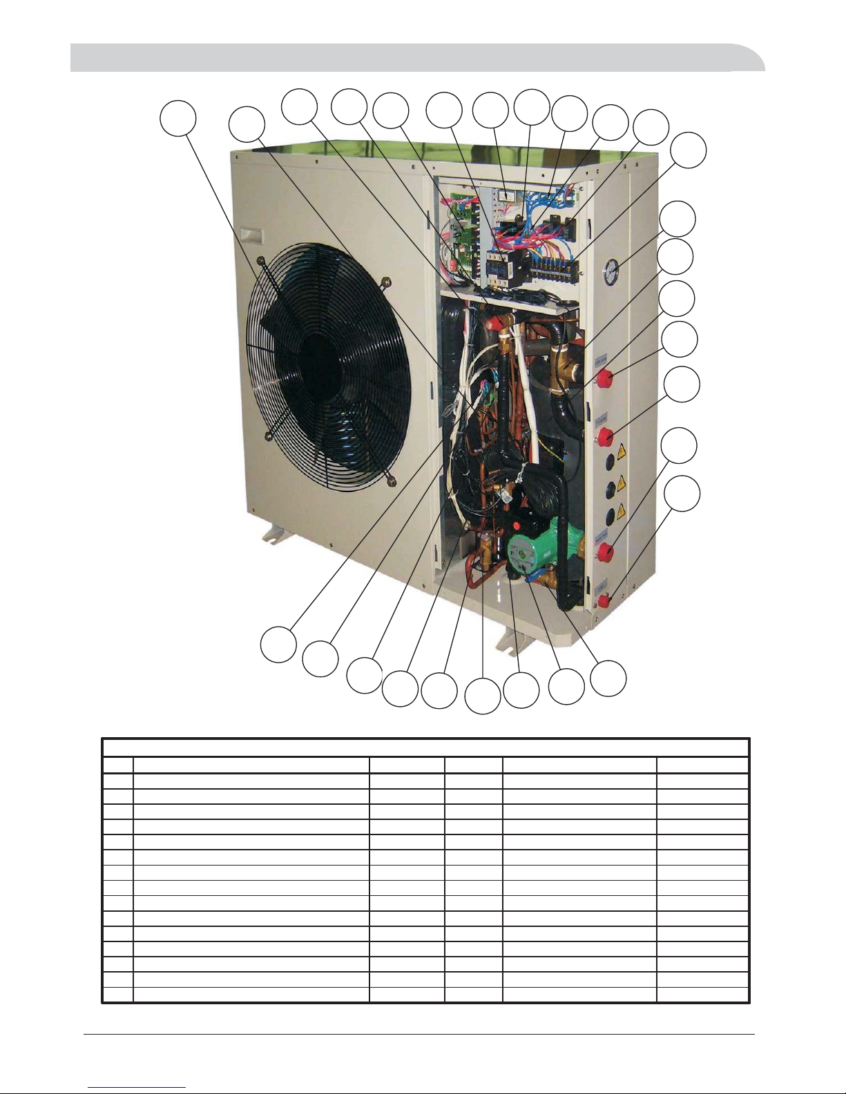
Parts List
NO. Description Quantity NO. Description Quantity
1Waterpressuregauge 1 16 Lowpressureswitch 1
2Electricalthree-wayvalve 1 17 Fan 1
3Compressor 1 18 R410ANeedlevalve 2
4D.H.Woutlet 1 19 Gas-liquidseparator 1
5A.Cwateroutlet 1 20 Safetyvalve 1
6 Water return 1 21 PCB 1
7Drain 1 22 ACcontactor 1
8Ballvalveswitch 1 23 Transformer 1
9Circulation mwater p optional 1 24 Fan motor capacitor 1pu ()
10 Temperature thermistor 7 25 Wire t rminals 3e
11 Thermal expansion valve 1 26 AC relay-1 1
12 Water differential pressure switch 1 27 AC relay-2 2
13 High-pressure reservoir 1 28 Power Terminal Block 1
14 Bypass solenoid valve 1
15 High pressure switch 2
Page 5
3Wiredcontroller
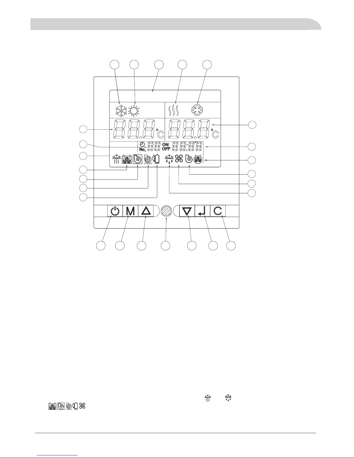
31DisplayandButton.
Notes:1.When the unit is freeze-proofing mode or defrost mode, and will appear or flicker.
2. If are solit,it means that the conponent is working,if they are hollow ,it means that
the conpenont is un-working.
3. DHW: A/C:Air conditioning.Domestic hot water;
3
Display
1.Cooling operation mode
2.Heating operation mode
3.Day display
4.DHW operation mode
5.Antibacterial(legionella)function
6.A/C returned water temp
or Outdoor ambient temp in only Heating series
7.Timer number
8.DHW temperature
or Outdoor ambient air temp in heating cooling series/
9.Clock
1 2
3
4
5
6
7
8
22
23
24
25
18
13
16
15
14
10.Anti-freezing running
11.A / C he ater
12.Main water pump C4
13.A/C water pump C6
14.Compressor
15.Defrost running
Button
19.ON/OFF button
20.Mode selector key
21.Up key
22.LED Indicator
23.Down key
24.Confirm key
25.Clear key
17
9
10
11
12
19 20 21
17.DHW water pump C5
18.DHW heater
16.Fan motor
123456
DAY
Sun
Page 6

32Operatingtheunit.
3.2 1 OPERATION MODE SHIFT (OPERATING STEPS)
3.2 2 modify the setting parameters (steps):
-
+->
-> + ->
-> . 』
.
.
,
-
』
:
A, in the On / Standby cases, press the M key, air conditioning cooling icon appears and flashes; press M
key every time to shift from air-conditioning cooling domestic hot water mode air conditioning
heating mode air conditioning heating domestic hot water mode domestic hot water mode
back to air conditioning cooling mode again When select a certain mode, press key to confirm,
the icon become solid and the heat pump will perform the selected mode .
B, When select air-conditioning cooling or heating plus domestic hot water, DHW will be priority
C, When select DHW mode only hot water operation, no air conditioning running.
D, Health and sterilization is an independent automatic operation mode, if necessary, modify the
parameters individually.
A, when the selected mode is running, the unit will run in accordance with the factory set default values,
or the last modification of the temperature.
B, the modification method of set the temperature value
In the On / Standby cases, press M and C keys at the same time 3 seconds, the current operation mode
flashes; by pressing the M key, you can switch the sequence in the following order: Cooling / heating /
hot water; by pressing to change set up fixed value, press button to
confirm and exit or exit amendment automatically after 15 seconds or press the C key to exit the
amendment.
C, the detailed settings in the table below:
the ▲ or ▼ key
3.2 4 key function description
A, to set any parameters that must press button to confirm to be valid, otherwise invalid.
B, in the parameter setting process, if more than 15 seconds there is no button operation, exit parameter
settings automatically, we have to pressed button to confirm the setting effective and if not pressed
button the setting is invalid.
3.2 5 C key function description
Click the C key to cancel current setting not confirmed by pressing button and exit setting.
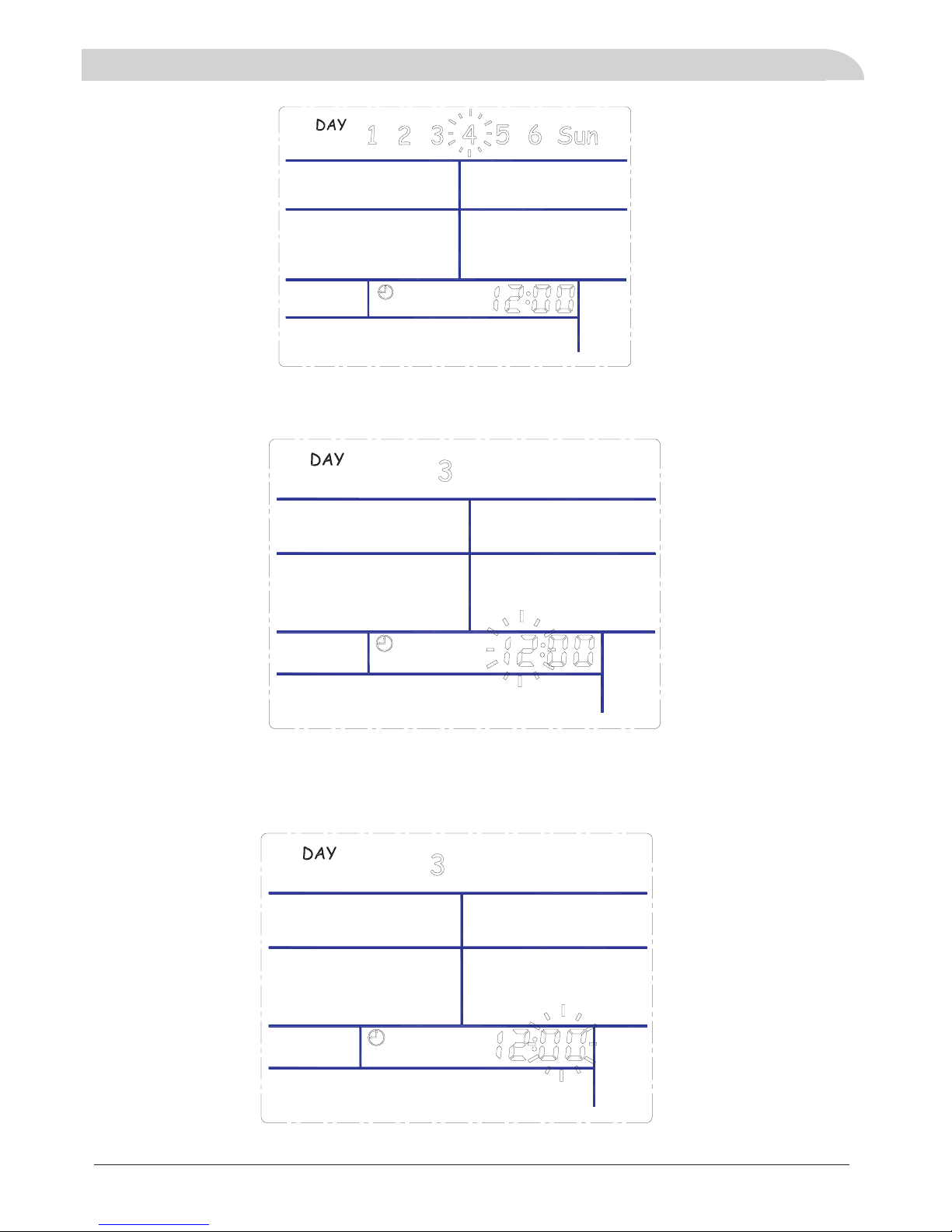
3.2 6 the current time adjustments (steps)
A, press M key 6 seconds, then release, week icon (for example, "4"), flashes. Press ▲ or ▼ selecting
between the 1-SUN and then key to confirm. As shown below:
-』
』
』』
,
-
』
-
』
"" temp .AU means automatic operation according to factory inner setting
3Wiredcontroller
4
,.The above AC Heating temp is returned water temp the actual outlet hot water temp is 5 C higher
Item Mode Setting Range Default Button operation to modify the
parameter
1A/C
Cooling
10℃~25℃ 12℃
M+C→M→▲or▼→』→C
2A/C
Heating
10℃~55℃(AU) 40℃
M+C→M→▲or▼→』→C
3DHW
10℃~60℃(AU) 50℃
M+C→M→▲or▼→』→C
4Antibacerial60℃~70℃ 65℃
M+C→M→▲or▼→』→C
3.2 3 Health and sterilization time setting (steps):
In the open / standby case, press M and C keys simultaneously for 3 seconds, press M button to make
Health sterilization icon (No. 4) appear and then press ▲ or ▼ key to set sterilization temperature value,
press button to confirm, the number of days appears and flashes, showing the original default settings or
7(means7days),press▲or▼keytoincreaseordecreaseinthenumberofdaysscheduledintervals,a
minimum of 7 days, a maximum of no more than 99 days, then press button to confirm the selection. " ON
"characters appear," hours "appears and flashes, showing the original settings or the default value (default
01: 1:00 a.m. start) , by pressing ▲ or ▼ key to change (0-23) and press button to confirm, that is, to run
the new start time. "ON" characters disappear, "OFF" characters appear, "minutes" appears and flashes ,
showing the original set or the default value (default 10), by pressing ▲ or ▼ key to change (minimum 10,
maximum of no more than 99), and then press button to confirm, after setting completion, exit
automatically; or automatically exit after 15 seconds.
-
』
』
』
』
Page 7
3Wiredcontroller
B, the clock icon appears, number of hours flashing, press ▲ or ▼ key to select number between
0~23,andthen keytoconfirm.』
C, at this time the number of minutes flashing, press ▲ or ▼ key to select number between
0~59,andthenpress buttontoconfirmandexitsettingautomaticallyafter15seconds,
or press C key to exit setting.
』
5
Page 8
3Wiredcontroller
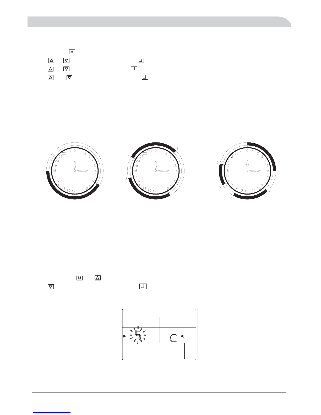
Tim ing 1 set on/ off e ach day Tim ing 2 sets on /of f eac h da y Timi ng 3set s on /off each da y
Need to set 2 time points Need to set 4 time points Need to set 6 time points
33WeekandClockSetting.
Press and hold key for 3 seconds until the week digits on the screen start flashing.
Press or to select the , press to confirm, the number of hour and
press or key to adjust hour, press to confirm, then minute and fl
press and key to adjust minute , press to confirm and exit set interface.
key day key appears flickers.
key the number of appears ickers.
up
Week ly t im er f un ct io n
There is a timer on the control system that can be used to program the time that the unit switches on and off.
turn onTiming is set to a cycle every week, Mon-Sun each day can be set three different time to ,and three
different time off, there is an option to select the time set for just one week effective and weekly repeat
circulation
to turn
effective.
Single week effective and effectiverepeated
,es“” “”
“” “” “”
“”
Press and hold and simultaneously for 3 seconds
key single week effective,
ialwayseffectivesingleweek effective .
the screen appears and flash S or C ,
press key to select S or C , press to confirm. Select S is choice
Cs , effectiveandcirculation timingsetinthesameway
Single week effective
circulation effective
6
Page 9

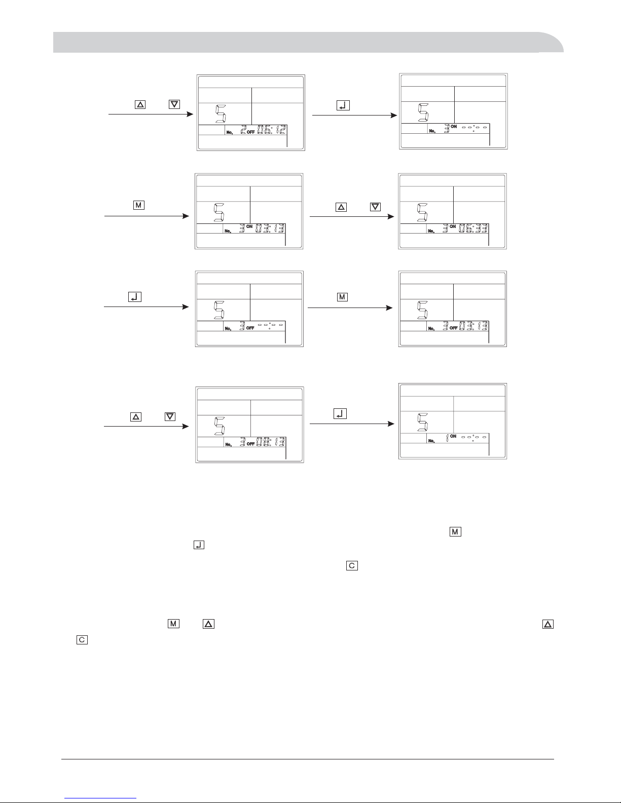
34Timersetting.
DAY
1
Press and hlod and
for 5 seconds
Press to select
Flicker
Press to active
Press and to
“”S
DAY
1
digital clock
DAY
1
adjust the time
3Wiredcontroller
DAY
DAY
1
1
Press to confirm
DAY
1
Press to activation
digital clock
Press and to
DAY
1
adjust the time
DAY
1
Press to confirm
Press to activation
digital clock
DAY
1
Press and to
adjust the time
DAY
1
Press to confirm
Press to activation
digital clock
DAY
1
7
Page 10
DAY
1
DAY
1
Press and to
adjust the time
Press to confirm
DAY
1
Press to activation
digital clock
DAY
1
Press and to
adjust the time
DAY
1
Press to confirm
DAY
1
Press to activation
digital clock
3Wiredcontroller
If a day does not need to change the timing settings, press the key to skip to the next day timer settings.
Clear timer settings
At the same time press and for seconds enter into the timer setting interface, and then press the
and for seconds, all the timer settings to be canceled.
3
simultaneously 3
adjust the time
DAY
1
Press and to
DAY
2
Press to confirm
After monday's timer setting is finished, it will be automatically switched to Tuesday's timer setting .until
sunday's timer setting is finished,then return to normal display interface.
In the process of setting the timer,if one of the timing time does not need to set,press key,the digits of clock
change to --:-- ,press the key to confirm.“”
8
Page 11

4ErrorCode
Shortly press you can enter into the error code checking state Then press key again you can check each error
code The error code meaning was given on the function book
Display Err Ex or Err Px For example Err E2 Err P5
,.,,
..
"""". : , .
9
Item Error Meaning Error Code Remark
1Compressorairdischargetempsensorerror P2
2Outdoorcoiltempsensorerror P1
3Outdoorambienttempsensorerror P7
4Airconditioningreturnedwatertempsensorerror P3
5AirconditioningOutletwatertempsensorerror E1
6DHWtankwatertempsensorerror E9
7Solartankwatertempsensorerror Pb
8Highpressureprotection E4
9Lowpressureprotection P9
10 Outdoor water flow error P8
11 Indoor water flow error Pd
12 Miss phase or wrong phase PA
13 Indoor freezing protection Pb
14 Compressor air discharge temp too high protection E3
Page 12

5Installation
51Installationinformation.
1
.needtochecktoensuretheminimumwaterflowvolumeshown
below, If necessary, install external water pumps for DHW circulation or for air conditioning circulation,
especially for under floor heating system or several floors application.
.
2Waterpumpcanbebuildinsideofoutsideaccordingtorequirement
Users need to install DHW water tank with coil heat exchanger built inside if this heat pump is used for
DHW together with air conditioning function.
3Evenwithbuiltinwaterpump,user
. .
Pipe connection
Note!
The pipe must be clean and has no dust and fragments inside.
DHW tank is too small then it may lead to rapid decline in water temperature during use, DHW tanks to use recommended
configuration as follows:
DHW tank
Recommended water volume :tank and minimum water flow volume
All outdoor pipes must be thermally insulated with at least 19 mm thick pipe insulation.
Pipe installation must be carried out in accordance with current standard and directives.
To keep the heat pump from freezing, please do not shut off the power supply of the heat pump in
winter. If the electricity is out of supply in winter, please drain out the water in the heat pump
(%%)
.
or you
can use brine mixed 20 to 40 glycol to replace pure water in case of electric cut off
accident during winter
DHW tank
Model 8KW 11KW 14-15KW 17-18KW 23KW
Piping connections of d mustomestic hot water and air-conditioning install filters.
≥300L
Pip connections must ensure no leakageing that it is .
10
DHW:Domestic hot water; A/C:Air conditioningNote:
A/C OUTLET
A/C and DHW INLET
DHW OUTLET
DRAIN
≥100L
≥100L ≥150L ≥200L
Minimum water
flow volume
(Liter Hour/)
1300L h/ 1800L h/ 2400L h/ 3000L h/ 3500L h/
Page 13

52Installationmethod.
5Installation
Method 1
11
Method 2
DHW with Room Heating
Page 14

1. C4 water pump and multifunctional box can be built inside of heat pump according to order requirement.
2. C4 water pump can be used for both DHW and air conditioning water circulation.
3. installer should check the actual water resistance and make sure to keep enough minimum water flow volume,
if necessary, more water pumps should be added for DHW (C5 water pump) and air conditioning(C6 water pump)
water circulation. The water pump connection can be found in wiring diagram.
4. Safety valve(air discharge valve) should be installed at the top of the circulation system for easy air discharge.
Air conditoning circulation can utilize the fan coil or radiator air discharge valve.
Method 4
Method 3
12
Note:
16/17 Air discharge valve(Safety Valve)
1. Heat Pump
2. Wired Controller
3. DHW water pump
4. DHW temp sensor
5. DHW water tank
6. Safety valve
7. Filter
8. Water pump ->C4
9. Drain valve
10. Ball valve
14. Expansion tank
12. Water pump ->C5
13. Water pump ->C6
C4
C6
C5
15. Multifunctional 3 way valve (can be installed inner or outside of heat pump unit)
G1
Page 15

53Installationwithsolarassistant.
5Installation
Application 1
Application 2
13
Page 16

53Installationwithsolarassistant.
5Installation
Application 3Themostenergysavingapplication
14
G2
G1 DHW and AC switching valve
G2 Solar automatic selection valve
:
:
Page 17

5Installation
15
W
B
5 3 Dimensions.
D
H
A
AH-8/9
1090
400
818
412
Model
W
D
H
A
810
B
AH-8/9
AH-14/15
W
D
H
B
Model
W
D
H
A
B
1090
400
412
1018
810
AH-14/15
A
Page 18

54Installationposition.
Installation in exceptional circumstances(unit:mm)
6 The unit must be installed upon reliable machine base or framework. Weight capacity of framework should be 3
times of the body weight, and safeguard measures should be taken to avoid malfunction of fastenings.
4 Ensure the unit is well ventilated, direction of air exhaust is kept away from windows of neighboring buildings, and
the exhaust air cannot flow back. moreover, adequate service clearance should be kept around the unit.
5 The unit should not be installed at places accompanied with oil, inflammable gases, corrosive components e.g.
sulfur compound, or high-frequency equipment.
1 If the unit is to be installed on the floor, its undercarriage should be heightened, to avoid ingression of accumulated
water in rainy season. In snowy areas, it is important to prevent accumulated snow from blocking up the air-out. The
recommended height is 20cm to 30cm.
2 Drain ditch or other facilities should be arranged under the outdoor unit,
to avoid the environment influence
because of water discharge.
3 To install the unit at balcony or top of building, the installation site must meet the allowable bearing capacity of
building structure, without affecting the structural safety.
7Theunitshouldnotbeinstalledatsiteswithtyphoon/earthquakehazards.Midairinstallationshouldbe
avoided as much as possible, for machine falling may result in severe accident.
Installation must be carried out by professional
personnel.
No obstacle in front of the unit
≥200
≥200
≥350
Outdoor unit
≥500
≥350
Obstacle above the unit
Note!
≥1000
Obstacle in front of the unit
Several units in a row
Outdoor unit
≥400
≥200
≥350
Outdoor unit
Outdoor unit
Outdoor unit
5Installation
16
Page 19

61General.
The heat pump must not be connected without the permission of the electricity supplier and must be
connected under the supervision of a qualified electrician.
The heat pump does not include an isolator switch on the incoming electrical supply. The power supply
cable must be connected to a circuit-breaker with at least a 3 mm breaking gap. Incoming supply must
comply with the technical requirements, with ground wire, via a distribution board with fuses.
Note!
Electrical installation and service must be
carried out under the supervision of a qualified
electrician. Electrical installation and wiring must
be carried out in accordance with the stipulations
in force.
Wires, spare parts and materials etc. must satisfy the relevant standards issued by the host country or region.
Isolator switch
If an insulation test is to be carried out in the building, please make sure to disconnect the heat pump.
To av o i d t h e p os s i bi l i t y o f f al s e a ct i o n c a u se d b y e le c tr o m ag n e t i c c ou p l i n g , t h e c o mm u n i c a ti o n w ir e m u s t
be STP(Shielded Twisted Pair). The size of communication wire should not less than 0.5mm .
2
6Electricconnection
17
Connection method between wired controller and control board
With n
:
onpolar double wires maximum 100m length.,
()*+,
Back of wire controller
Page 20

6Electricconnection
63WiringDiagram.
18
Water
pump
C4
C5
C6
The parts with dotted circle are optional parts
according to actual installation requirement.
C4: water pump for both DHW and A/C
C5: water pump is addtional option for DHW
C6: water pump is additional option for A/C
C4 water pump is not built inside for
standard model. There will be C4
connection port at the terminals in that case.
Single Phase
Page 21

After finish the installation tasks, please check the items:
1Checkthedipswitchsettingandshortwiringasshownbelowtobesureofcorrectelectrictyconnection.
The DIP switch can only be set at factory or by authorized engineer Any improper setting may cause
unrecoverable damage or misfunction..
2cable
3 Wa ter cir cui t
Check if the power cable is connected correctly, and check if the screws have been screwed down.
Check if the water pipes are correctly connected, and the pipe dimensions are correct.
Check if all the shut off valve and manual valve is opened, check if all the joint is fastened.
Heatproof measures must be taken for water outlet pipes and water inlet.
Please use specified cables.communcation
Tur n on the heat p ump
select or not,tcooling, heating, domestic hot water mode , check whether the unit is running properly he
compressor will be started in 3~5 minute after powered on.
: .Note Please only select heating model before assuring the water pump is working properly
SW4 1 Single phase:-:
O
N
1
2
4
Three phase:
’
Running
7TestRun
71Preparation.
Before fill the water to heat pump water system please make sure the whole water system is
connected correctly all the piping joints are fasten good
,
,.
’
Our heat pump has antifreeze function if the electricity is connected. So please keep the electricity always
connected even when you don t use the heat pumps If you don t want to use the heat pumps for
long time in winter or if the electricity is cut off by accident for more than 30 minutes, you need to drain out
all the recycling water to protect the heat pump to be freezen.
In cold area for the safety, you d better use brine as the fluid in the heat pump water system instead of
pure water. If the lowest air temperature come to -10°C , you need add 25% C2H602 (Ethylene glycol) to the
clean pure water. If the lowest air temperature come to -25°C, you need to add 40% C2H602 to the clean
water.
'.'
,'
Important Notice for Antifreeze to Avoid heat pump broken
Two method of water filli ng
1Forsimilarinstallationsystemasinstallationmethod1,pleaseopenthetapwatervalve,openballvalve
10, air discharge valve 15 and water tank air discharge valve, until the water is full. Then close air discharge
valve15 , ball valve 10 and water tank air discharge valve.
2Forsimilarinstallationsystemasinstallationmethod2,pleaseopenthetapwatervalve,openballvalve
10, 15, air discharge 16, air discharge 17 and water tank air discharge valve, until the water is full. Then close
air discharge valve 16,17, ball valve10,15 and water tank air discharge valve.
、
、,
72Waterfilling.
19
3
O
N
1
2
4
3
TRAN
N4
N3
N2
N1
N10
N12
N11
N13
SW4
An6
An1
O
N
1
2
4
3
Sw5
O
N
1
2
4
3
Page 22
9Temperaturesensordata
The temperature sensor data for water outlet sensor, water inlet sensor, coil pipe sensor,
ambient sensor, DHW sensor, Etc.
The sensor model is 3470RT
R25=5KΩ+-1%
A/D RT(KΩ)t2(℃)HL A/DRT(KΩ)t2(℃)HL
10 105.780 -36.9 0 10 132 4.039 30.6 8 4
12 87.433 -33.8 0 12 134 3.915 31.4 8 6
14 74.329 -31.1 0 14 136 3.794 32.2 8 8
16 64.500 -28.7 1 0 138 3.677 33.1 8 10
18 56.856 -26.5 1 2 140 3.563 33.9 8 12
20 50.740 -24.5 1 4 142 3.452 34.8 8 14
22 45.736 -22.6 1 6 144 3.344 35.7 9 0
24 41.567 -20.9 1 8 146 3.240 36.5 9 2
26 38.038 -19.2 1 10 148 3.138 37.4 9 4
28 35.014 -17.7 1 12 150 3.039 38.3 9 6
30 32.393 -16.2 1 14 152 2.942 39.2 9 8
32 30.100 -14.8 2 0 154 2.848 40.1 9 10
34 28.076 -13.5 2 2 156 2.756 41.1 9 12
36 26.278 -12.2 2 4 158 2.667 42.0 9 14
38 24.668 -10.9 2 6 160 2.580 43.0 10 0
40 23.220 -9.7 2 8 162 2.495 43.9 10 2
42 21.910 -8.6 2 10 164 2.412 44.9 10 4
44 20.718 -7.4 2 12 166 2.331 45.9 10 6
46 19.630 -6.3 2 14 168 2.252 46.9 10 8
48 18.633 -5.2 3 0 170 2.175 47.9 10 10
50 17.716 -4.2 3 2 172 2.100 49.0 10 12
52 16.869 -3.2 3 4 174 2.026 50.1 10 14
54 16.085 -2.2 3 6 176 1.955 51.1 11 0
56 15.357 -1.2 3 8 178 1.884 52.3 11 2
58 14.679 -0.2 3 10 180 1.816 53.4 11 4
60 14.047 0.7 3 12 182 1.748 54.6 11 6
62 13.455 1.7 3 14 184 1.683 55.7 11 8
64 12.900 2.6 4 0 186 1.618 57.0 11 10
66 12.379 3.5 4 2 188 1.555 58.2 11 12
68 11.888 4.4 4 4 190 1.494 59.5 11 14
70 11.426 5.3 4 6 192 1.433 60.8 12 0
72 10.989 6.1 4 8 194 1.374 62.2 12 2
74 10.576 7.0 4 10 196 1.316 63.6 12 4
76 10.184 7.8 4 12 198 1.260 65.0 12 6
78 9.813 8.7 4 14 200 1.204 66.5 12 8
80 9.460 9.5 5 0 202 1.150 68.1 12 10
82 9.124 10.4 5 2 204 1.096 69.7 12 12
84 8.805 11.2 5 4 206 1.044 71.3 12 14
86 8.500 12.0 5 6 208 0.992 73.1 13 0
88 8.209 12.8 5 8 210 0.942 74.9 13 2
90 7.931 13.6 5 10 212 0.892 76.8 13 4
92 7.665 14.5 5 12 214 0.844 78.7 13 6
94 7.411 15.3 5 14 216 0.796 80.8 13 8
96 7.167 16.1 6 0 218 0.750 83.0 13 10
98 6.933 16.9 6 2 220 0.704 85.3 13 12
100 6.708 17.7 6 4 222 0.659 87.8 13 14
102 6.492 18.5 6 6 224 0.614 90.4 14 0
104 6.285 19.3 6 8 226 0.571 93.3 14 2
106 6.085 20.1 6 10 228 0.528 96.3 14 4
108 5.893 20.9 6 12 230 0.486 99.6 14 6
110 5.707 21.7 6 14 232 0.445 103.2 14 8
112 5.529 22.5 7 0 234 0.404 107.1 14 10
114 5.356 23.2 7 2 236 0.364 111.5 14 12
21
Page 23

9Temperaturesensordata
The temperature sensor data for c ompressor exhaust gas temperature s ensor.
The sensor model is 3950RT
R25=10KΩ ,B25/50=3950
A/D RT(KΩ )t2(℃ )HL A/DRT(KΩ )t2(℃ )HL
10 246.000 -33.0 0 10 132 9.394 26.4 8 4
12 203.333 -30.2 0 12 134 9.104 27.1 8 6
14 172.857 -27.7 0 14 136 8.824 27.8 8 8
16 150.000 -25.6 1 0 138 8.551 28.6 8 10
18 132.222 -23.6 1 2 140 8.286 29.3 8 12
20 118.000 -21.8 1 4 142 8.028 30.0 8 14
22 106.364 -20.1 1 6 144 7.778 30.8 9 0
24 96.667 -18.6 1 8 146 7.534 31.5 9 2
26 88.462 -17.1 1 10 148 7.297 32.3 9 4
28 81.429 -15.7 1 12 150 7.067 33.0 9 6
30 75.333 -14.4 1 14 152 6.842 33.8 9 8
32 70.000 -13.1 2 0 154 6.623 34.6 9 10
34 65.294 -12.0 2 2 156 6.410 35.3 9 12
36 61.111 -10.8 2 4 158 6.203 36.1 9 14
38 57.368 -9.7 2 6 160 6.000 36.9 10 0
40 54.000 -8.6 2 8 162 5.802 37.8 10 2
42 50.952 -7.6 2 10 164 5.610 38.6 10 4
44 48.182 -6.6 2 12 166 5.422 39.4 10 6
46 45.652 -5.6 2 14 168 5.238 40.3 10 8
48 43.333 -4.7 3 0 170 5.059 41.2 10 10
50 41.200 -3.8 3 2 172 4.884 42.0 10 12
52 39.231 -2.9 3 4 174 4.713 42.9 10 14
54 37.407 -2.0 3 6 176 4.545 43.8 11 0
56 35.714 -1.1 3 8 178 4.382 44.8 11 2
58 34.138 -0.3 3 10 180 4.222 45.7 11 4
60 32.667 0.6 3 12 182 4.066 46.7 11 6
62 31.290 1.4 3 14 184 3.913 47.7 11 8
64 30.000 2.2 4 0 186 3.763 48.7 11 10
66 28.788 3.0 4 2 188 3.617 49.8 11 12
68 27.647 3.8 4 4 190 3.474 50.8 11 14
70 26.571 4.5 4 6 192 3.333 51.9 12 0
72 25.556 5.3 4 8 194 3.196 53.1 12 2
74 24.595 6.1 4 10 196 3.061 54.2 12 4
76 23.684 6.8 4 12 198 2.929 55.4 12 6
78 22.821 7.5 4 14 200 2.800 56.7 12 8
80 22.000 8.3 5 0 202 2.673 57.9 12 10
82 21.220 9.0 5 2 204 2.549 59.3 12 12
84 20.476 9.7 5 4 206 2.427 60.6 12 14
86 19.767 10.4 5 6 208 2.308 62.1 13 0
88 19.091 11.1 5 8 210 2.190 63.6 13 2
90 18.444 11.8 5 10 212 2.075 65.1 13 4
92 17.826 12.5 5 12 214 1.963 66.7 13 6
94 17.234 13.2 5 14 216 1.852 68.4 13 8
96 16.667 13.9 6 0 218 1.743 70.2 13 10
98 16.122 14.6 6 2 220 1.636 72.1 13 12
10 0 15 .6 00 15 .3 6 4 2 2 2 1 .5 32 7 4 .1 1 3 14
10 2 15 .0 98 16 .0 6 6 2 2 4 1 .4 29 7 6 .3 1 4 0
10 4 14 .6 15 16 .7 6 8 2 2 6 1 .3 27 7 8 .6 1 4 2
10 6 14 .1 51 17 .4 6 10 2 2 8 1 .2 28 8 1 .0 1 4 4
10 8 13 .7 04 18 .1 6 12 2 3 0 1 .1 30 8 3 .7 1 4 6
11 0 13 .2 73 18 .8 6 14 2 3 2 1 .0 34 8 6 .5 1 4 8
11 2 12 .8 57 19 .5 7 0 2 3 4 0 .9 40 8 9 .7 1 4 10
11 4 12 .4 56 20 .1 7 2 2 3 6 0 .8 47 9 3 .2 1 4 12
11 6 12 .0 69 20 .8 7 4 2 3 8 0 .7 56 9 7 .1 1 4 14
11 8 11 .6 95 21 .5 7 6 2 4 0 0 .6 67 10 1 .5 1 5 0
12 0 11 .3 33 22 .2 7 8 2 4 2 0 .5 79 10 6 .6 1 5 2
12 2 10 .9 84 22 .9 7 10 2 4 4 0 .4 92 11 2 .6 1 5 4
12 4 10 .6 45 23 .6 7 12 2 4 6 0 .4 07 11 9 .9 1 5 6
12 6 10 .3 17 24 .3 7 14 2 4 8 0 .3 23 12 9 .2 1 5 8
12 8 10 .0 00 25 .0 8 0 2 5 0 0 .2 40 14 1 .7 1 5 10
13 0 9. 69 2 25 .7 8 2
22
Page 24

Better to print this page out and make sure that you can tick all ot fhe following items to avoid any
Problem After finish the installation tasks please check the item listed below before turn on heat
pump
.,
.
’
10 Heat Pump Test Run
Check list before turn on heat pump
Things you should have done:
1Powercable
Check if the power cable is connected correctly and check if the screws have been screwed
down and tight Please use specified cables
2Communicationwire
Check if the communication wire is connected correctly and check if the screws have been
screwed down and tight Please adopt specified communication wire
3Watercircuit
aCheckifthewaterpipesarecorrectedandthepipedimensionsarecorrect
bCheckifalltheshutoffvalveandmanualvalveisopenedcheckifallthejointisfastened
CCheckifairexhaustvalvesonthewaterterminalsmustbeopenforthe1stwaterrecycle
running to exhaust air in the terminals This valve can be closed when this valve drain
continous water
DCheckifairexhaustvalvesforthewholewatercircuitisopennedAnautomaticpurging
device has to be installed at the highest point of the water circuit
EOpenthemaintenancescrewinthemiddleofthewaterpump forbothDHWandair
conditioning circuit and manually rotate the water pump axis This action should also be
done when electric power disconnected for more than 24 hours to avoid block
4BesurethetwowatertanksarefullofwaterIfthewatertanksareemptytheelectricheaters
inside is dangerous to be broken
5Insulationtestofpowersupplycircuit Pleaseinspectitbyaohmmeterof500V Applythe
voltage of DC 500V between the power supply terminal block and the ground wire test the
insulation resistance The insulation resistance must be more than 2 ohms
.
,
..
.
,
..
.
-. , .
-. , .
-.
.
.
-. .
.
-. (
).
.
..,
.
.. .
,
..
Heat Pump Test Run Produre
Switch on the power supply
1Thepowerindicator LED willbelightedThecompressorheaterwillbestarted
2Turnontheheatpumpandcheckiftheheatpumpisinairconditioningmode ifnot
please press M button on the LED controller to change the operation mode to heating
mode
3Thecirculationpumpwillstartbeforethecompressor Makesurethewaterpumpis
working well
4Thecompressorwillbestartedin3minuteafterpoweredon
.(). .
. ,,
.
..
.
..
MOST IMPORTANT!
1Makesureitisnotincoolingmode duringfirstoperationortestruninguntilyoumakesure
the air conditioning water pump is working properly and water circuit is recycling smoothly
2Selectabigenoughwaterpumpfortheairconditioningwatercircuit
3Alwayskeeptheelectricityconnectionwithheatpumptoenabletheantifreezefunction
. ,
.
. .
. .
Yes
Yes
Yes
Yes
Yes
Yes
Yes
Yes
Yes
Yes
Yes
Yes
Yes
Yes
Yes
23
Page 25

 Loading...