

Page 1
WATER SOURCE GEOTHERMAL
HEATING COOLING HEAT PUMP
/
&
Installation and Operation Manual
China Palm A C Equipment Co Ltd/& .,
GH Close Loop SeriesOH Open Loop Series-
Page 2

Content
1
11
12
2
3
31
32
33
34
4
5
51
52
53
6
61
62
63
7
71
72
8
Safety Precautions
Components
Wired con trolle r
Error code
Installation
Electric connection
Test ru n
Technical data
9
.
.
.
.
.
.
.
.
.
.
.
.
.
.
General
Transpor t and storage
Display and button
Operating the unit
Week and c lo ck setti ng
Timer setti ng
Installation information
Installation method
Dimensions
General
Cable connection
Wiring diagram
Preparation
Wat er replen ishin g
Check list before turn on heat pump
............................................................3
.....................................................1
................................................................1
...................................................1
........................................................4
.......................................................4
......................................................5
.................................................7
..........................................................8
.............................................................10
.............................................................11
..................................................11
.....................................................12
............................................................14
....................................................15
................................................................15
.......................................................15
.........................................................16
................................................................18
............................................................18
......................................................19
.........................................................20
...............................21
Page 3

1SafetyPrecautions.
Note!
It is required to read the Safety precautions in detail before
operation. The precautions listed below are all-important for
safety, please obey without fail.
Make sure that the fixed ground wire in the building is securely connected to earth.
Wiring tasks should be carried out by qualified electricians only, in addition, they should check the safety conditions
of power utilization, for example, check if the line capacity is adequate, and check if the power cable is damaged.
Users must not install, repair or relocate the unit.
Improper treatment might lead to the accidents e.g. personal injury caused by fire, electrical shock or unit's fallingoff, and water leakage in the machine. Please contact professional repair and service department of local dealer.
In case the leaked gas is congregated around the machine, there might be the risk of explosion.
The unit shall not be installed at a spot with potential hazard of leakage of inflammable gas.
If the foundation is unstable, the outdoor unit may drop and cause a casualty accident. so this must be validated carefully.
Make sure that the foundation of installation is stable.
If no electric leakage protection switch is fitted at the beginning of the electric supply, it maybe cause electric shocks or
fires.
Make sure that the electric leakage protection switch is fixed.
Before cleaning, shut off the electric supply of the unit firstly to avoid injuries caused by fan in operation.
Do not rinse the unit by water because the rinsed unit may cause electric shock.
Please observe the follow items when cleaning the unit..
Make sure to shut off the electric supply before maintain the unit.
Please do not insert fingers or sticks into air outlet or air inlet.
The machine must be transported and stored vertically.
1 1 General.
If any abnormity occurs in the unit (such as burned taste inside the unit), cut off the power supply immediately,
and contact professional repair and service department of local dealer.
The machine must be transported and stored vertically.
1 2 Transport and storage.
2
Page 4
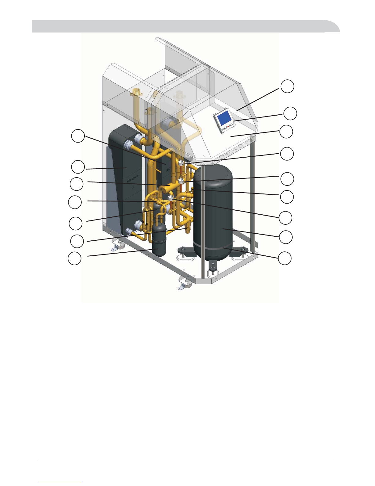
2Components
3
1
16
5
7
6
8
3
2
4
15
10
9
11
13
12
14
16 LCD Controller
1WEO ZJ17 005 Electric box 9 X T13 001 Liquid gas isolator
2WEO ZX17 018 Filter 10 X T13 000 Liquid accumulator
3WEO ZX17 019 Heat Exchanger 11 X T16 000 needle valve
4AQD IX A20 002 Heat Exchanger 12 X T03 000 Heat expansion valve
5XT09 0002 High pressure switch 1 13 D T01 001 Compressor
6XT09 0003 High pressure switch 2 14 D T08 000 Crancase Heater
7XT09 0004 Low pressure switch 15 Control board
8XT06 0003 4 way valve
Page 5
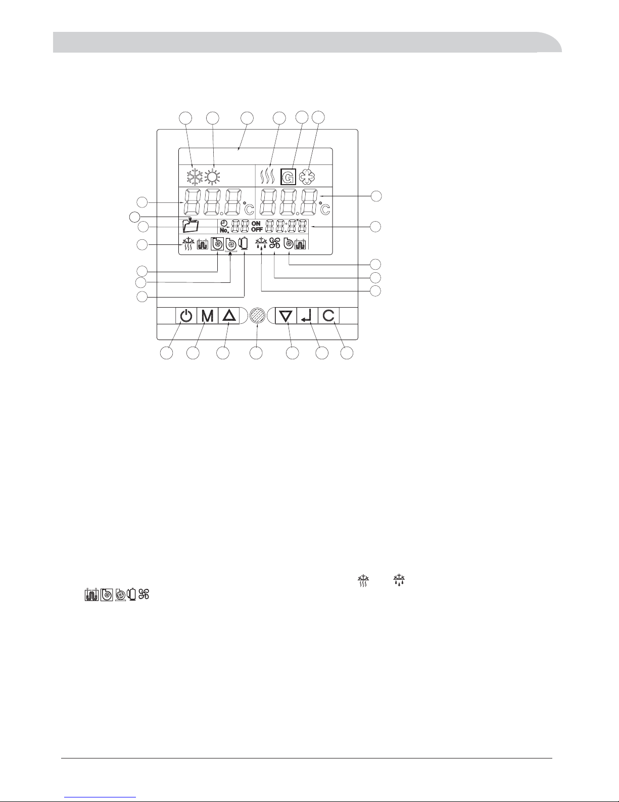
3Wiredcontroller
Display
31DisplayandButton.
1.Cooling operation mode
2.Heating operation mode
3.Day display
4.DHW operation mode
5.A C temperature/
(Heating or Cooling)
6.Menu
7.Timer
8.DHW temperature
9.Clock
10.Anti-freezing running
Button
19.ON/OFF button
20.Mode selector key
21.Up key
22.LED I (Reserved)ndicator
23.Down key
24.Confirm (enter) key
25.Clear(Cancel) key
Notes:1.When the unit is freeze-proofing mode or defrost mode, and will appear or flicker.
2. If are solit,it means that the conponent is working,if they are hollow ,it means that
the conpenont is un-working.
3. DHW: A/C:Air conditioning.Domestic hot water;
17.DHW assistant water pump(C5)
12.Main water pump(C4)
14.Compressor
15.Defrost running
16.Water source water pump(C2)
4
123456
1 2
3
4
5
7
8
22
23
24
25
16
15
14
17
9
10
12
19 20 21
DAY
Sun
6
13
18
13.Geothermal icon
18.Antibacterial function
4Tocheck4sensorstemp.
,/ .
.,
.
(), ()
.
During On mode Icon 6 shows Room Heating cooling returned water temp to heat pump
Actual outlet water temp is 5 C higher than the figure Icon 8 is DHW tank temp sensor
you need to put this sensor to the water tank temp port
Outside air temp sensor code 10 Air Conditioning outlet water temp sensor code 49
can be checked according to parameter table in installer manual
11
11.A C assis t ant w ater pump(C 6 )
Page 6

32Operatingtheunit.
3.2 1 OPERATION MODE SHIFT (OPERATING STEPS)
3.2 2 modify the setting parameters (steps):
-
』
-
』
:
A, in the On / Standby cases, press the M key, cooling icon appears and flashes; press M key
again to change into air-conditioning heating , and flashes; press M key again icon to change
domestic hot water and flashes; press M key again to return to cooling. When select a certain
mode, press key to confirm, the icon still. Unit will perform the selected.
B, the selected air-conditioning refrigeration, heating mode also includes a domestic hot water,
running hot water first.
C, selection of hot water that is only hot water, no air conditioning running.
D, Health and sterilization is an independent automatic operation mode, if necessary, modify the
parameters individually.
A, when the selected mode is running, the unit will run in accordance with the factory set default values,
or the last modification of the temperature.
B, the modification method of set the temperature value
In the On / Standby cases, press M and C keys at the same time 3 seconds, the current operation mode
flashes; by pressing the M key, you can switch the sequence in the following order: Cooling / heating /
hot water; by pressing to change set up fixed value, press button to
confirm and exit or exit amendment automatically after 15 seconds or press the C key to exit the
amendment.
C, the detailed settings in the table below:
the ▲ or ▼ key
3.2 3 key function description
3.2 4 C key function description
-』
』
』
』
-
』
A, to set any parameters that must press button to confirm to be valid, otherwise invalid.
B, in the parameter setting process, if more than 15 seconds there is no button operation,
exit parameter settings automatically, we have pressed button to confirm the setting
effective and not pressed button to confirm the setting is invalid.
Click the C key to cancel current setting not confirmed by pressing button and exit setting.
No Mode Setting range Default The buttons operation of modify
the setting parameters
1A/Ccooling10℃~25℃ 12℃
M+C→M→▲or▼→』
2A/CHeating10℃~60℃(AU) 40℃
M+C→M→▲or▼→』
3D.H.W.10℃~60℃(AU) 45℃
M+C→M→▲or▼→』
4VirusKilling
function of D.H.W.
60℃~70℃ 65℃
M+C→M→▲or▼→』
"" temp .AU means automatic operation according to factory inner setting
3Wiredcontroller
5
,.The above temp is returned water temp the actual outlet hot water temp is 5 C higher
A/C
Page 7
3Wiredcontroller
B, the clock icon appears, number of hours flashing, press ▲ or ▼ key to select number between
0~23,andthen keytoconfirm.』
C, at this time the number of minutes flashing, press ▲ or ▼ key to select number between
0~59,andthenpress buttontoconfirmandexitsettingautomaticallyafter15seconds,
or press C key to exit setting.
』
6
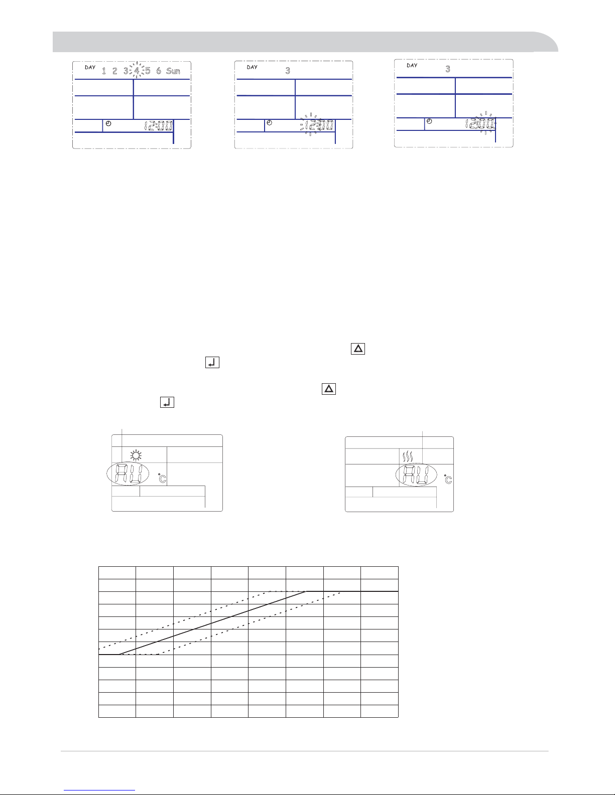
3.2 5 the current time adjustments (steps)A, press M key 6 seconds, then release, week icon (for example, "4"), flashes. Press ▲ or
▼selectingbetweenthe1-SUNandthen keytoconfirm.Asshownbelow:』
Automatic heating temperature
Heating "AU" flicker
Heating temp auto
DHW temp auto
DHW "AU" flicker
In air
Conditioning heating mode and DHW mode, we provide two special temperature settings.that is
Heating temp auto:when modify heating temp to 50ºC, press the key again,on the temp area " AU" Symbol
appears and flickers,press the key to confirm,the heating temp will be automatic setting by outdoor
ambient temperature.
DHW temp auto:when modify DHW temp to Press the key again,on the temp area "AU"symbol appears
and flickers,press the key to confirm,the DHW temp will be automatic setting by outdoor ambient temperature.
In some areas, air conditioning built-in automatic temperature curve may be not ideal for local users, installed
by professional installers of automatic parameter adjustment curve,Adjust the range of -5ºC~+5ºC as~
the table below:
20 15 10 5 0 -5 -10 -15
0
5
10
15
20
25
30
35
40
45
50
55
60
25
Outdoor ambient
Heating
set temperature
1
2
3
Automatic
temperature curve
factory setting is curve 22 ,user
can
offset automatic temperature
curve
by setting Parameter "25"Parameter "25"
Curve1:parameters "25" = 1 0"25" =10
Curve2:parameters
"25" = 5"25" =5
Curve3:parameters
"25" = 0"25" =0
Automatic heatingAutomatic heating Te m p function.
50ºC,
Page 8
3Wiredcontroller
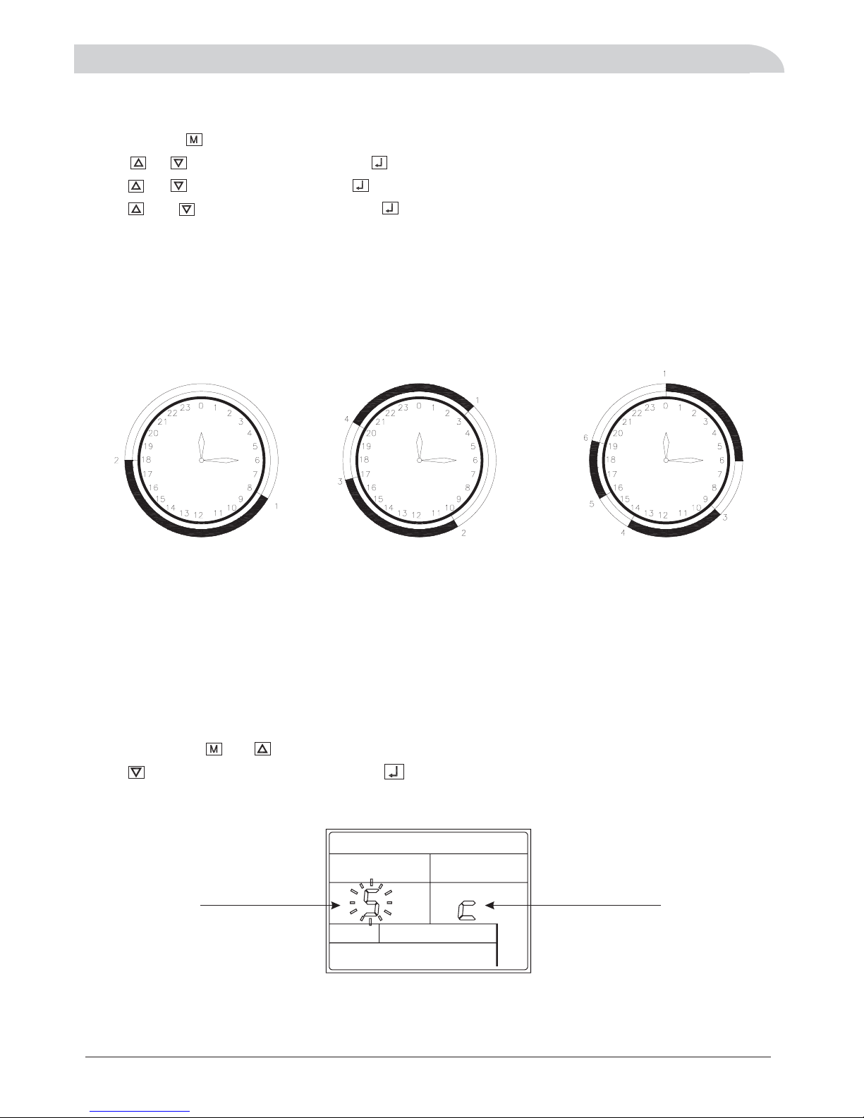
Timing 1set on/off each day Timing 2sets on/off each day Timing 3sets on/off each day
Need to set 2 time points Need to set 4 time points Need to set 6 time points
33WeekandClockSetting.
Press and hold key for 3 seconds until the week digits on the screen start flashing.
Press or to select the , press th number f h ur, to co firm and
press or pre s, key to adjus hour th n, to co firm minute and fl
press and pre s, key to adjust m nute to confirm and exit set interface.
key day key appears flickers.
key the number of appears ickers.
up
Weekly timer function
Single week effective and circulation effective
,es“” “”
“” “” “”
“”
Press and hold and simultaneously for 3 seconds
key single week effective,
icirculationeffectivesingleweek effective .
the screen appears and flash S or C ,
press key to select S or C , press Se ect. to onfirm S is choice
Cs , effectiveandcirculation timingsetinthesameway
Single week effective
circulation effective
7
There are timers on the control system that can be used to program the time when the unit switches on and
off.
Timer can be set to a cycle every week, since Mon to Sun. each day can be set three different timers to turn
on, and three different timers to turn off. There is an option to select the timer set for just one week or weekly
repeated.
Page 9

34Timersetting.
DAY
1
Press and hlod and
for 5 seconds
Press to select
Flicker
Press to active
Press and to
“”S
DAY
1
digital clock
DAY
1
adjust the time
3Wiredcontroller
DAY
DAY
1
1
Press to confirm
DAY
1
Press to activation
digital clock
Press and to
DAY
1
adjust the time
DAY
1
Press to confirm
Press to activation
digital clock
DAY
1
Press and to
adjust the time
DAY
1
Press to confirm
Press to activation
digital clock
DAY
1
8
Page 10

DAY
1
DAY
1
Press and to
adjust the time
Press to confirm
DAY
1
Press to activation
digital clock
DAY
1
Press and to
adjust the time
DAY
1
Press to confirm
DAY
1
Press to activation
digital clock
3Wiredcontroller
If a day does not need to change the timing settings, press the key to skip to the next day timer settings.
Clear timer settings
At the same time press and for seconds enter into the timer setting interface, and then press the
and for seconds, all the timer settings to be canceled.
3
simultaneously 3
adjust the time
DAY
1
Press and to
DAY
2
Press to confirm
After monday's timer setting is finished, it will be automatically switched to Tuesday's timer setting .until
sunday's timer setting is finished,then return to normal display interface.
In the process of setting the timer,if one of the timing time does not need to set,press key,the digits of clock
change to --:-- ,press the key to confirm.“”
9
Page 11

4ErrorCode
Shortly press you can enter into the error code checking state Then press key again you can check each error
code The error code meaning was given on the function book
Display Err Ex or Err Px For example Err E2 Err P5
,.,,
..
"""". : , .
10
Item Error Meaning Error Code
1Compressorairdischargetempsensorerror P2
2Outdoorcoiltempsensorerror P1
3Outdoorambienttempsensorerror P7
4Air-conditioningreturnedwatersensorfailure P3
5Air-conditioningoutletwatersensorfault E1
6Hotwatertanksensorfault E9
7Solartempsensorerror Pb
8highpressureprotection,orwatersourcesidewater
flow volume too small
E7
9Lowpressureprotection P9
10 Outdoor Water flow error P8
11 Indoor Water flow error, A C freezing protection Pd
12 Missing phase / Wrong phase PA
13 Indoor freezing protection Pb
14 Water source inletwater temp error EF
15 Water source outlet water temp error EA
16 Water source heat exchange noefficient error E8
17 Air discharge temp toohigh protection E3
18 high pressure protection E4
5Installation
51Installationinformation.
Note!
DHW tank is too small then it may lead to rapid decline in water temperature during use, DHW tanks to use
recommended configuration as following :tank and minimum water flow volumeRecommended water volume :
DHW tank
To keep the heat pump from freezing, please do not shut off the power supply of the heat pump in
winter. If the electricity is out of supply in winter, please drain out the water in the heat pump
.
( %- % )
or you
can use brine 20 40 glycol to replace pure water in case of electric cut off accident during
winter
DHW tank
Model GH 8 GH 11 GH 15 GH 17 GH-30--- -
≥300L
≥100L
≥100L ≥150L ≥200L
Water
flow volume
(Liter Hour/)
1200L h/ 1800L h/ 2400L h/ 3000L h/ 3500L h/
Page 12

Pipe connection
The pipe must be clean and has no dust and fragments inside.
All outdoor pipes must be thermally insulated with at least 19 mm thick pipe insulation.
Pipe installation must be carried out in accordance with current standard and directives.
Pip connections must ensure no leakageing that it is .
11
DHW:Domestic hot water; AC:Air conditioning
Note:The above inlets and outlets may be changed without notice Please check the sticker
on the unit as final..
DHW AC WATER INLET
/
DHW AC WATER OUTLET
/
GEO SOURCE OUTLET
GEO SOURCE INLET
Close Loop AC Series Standard Geo
Water source heat pump inlets and outlets
:/
Close Loop HC Series Multifunctional Geo
Water source heat pump inlets and outlets
:/
DHW AC WATER INLET/
AC WATER OUTLET
GEO SOURCE OUTLET
GEO SOURCE INLET
DHW HOT WATER OUTLET
Open Loop Standard
Geo
Water source heat pump inlets and outlets
:/
GEO SOURCE CONNECTION
AC DHW INLET
&
AC OUTLET
DHW OUTLET
INLET SENSOR
OUTLET SENSOR
11K W and a bov e mode l
11K W and a bov e mode l
8KW and below model
8KW and below model
GEO SOURCE OUTLET
GEO SOURCE INLET
DHW AC WATER INLET
/
DHW AC WATER OUTLET
/
GEO SOURCE INLET
DHW HOT WATER OUTLET
DHW AC WATER INLET/
AC WATER OUTLET
GEO SOURCE OUTLET
During Piping connections, filters of domestic hot water and air-conditioning must be install.
5Installation
5Installation
DHW AC WATER INLET/
AC WATER OUTLET
GEO SOURCE OUTLET
GEO SOURCE INLET
DHW HOT WATER OUTLET
25KW/30KW
25KW/30KW
DHW AC WATER INLET/
AC WATER OUTLET
GEO SOURCE OUTLET
GEO SOURCE INLET
Page 13

52HeatRecoveryModuleConnection.
5Installation
Our heat recovery module can be connected with any of our basic
GH series to upgrade the normal water source heat pump to heat
recovery model with Heating Cooling and domestic hot water function
in the same time To be sure the following correct port connection and
electric connection
,
.
..
AC
12
C2 Water source side water pump
C4 Usage side main water pump for DHW and AC
C5 DHW assistant water pump
C6 AC assistant water pump
Page 14

Tank Sensor
500L tank with dual coils
(Each coil is 20M length or more)
PCB
Sensor
Radiator
Sensor
PCB
Comp
H.E.
()*
PCB
4
5
User Side
Heat Pump
Circulation pump C2
Water source
UnderfloorHeating
&Cooling
Floor Ceiling Heating
&Cooling
Water Fan coil
H.E.
COOLING
WATERIN
PCB
SensorSensor
PCB
ISOLATOR
H.X.1
H.X.2
Expansion
6
4
7
5
Filter
Radiator
Water Fan Coil
Under Floor Heating
Exposure Water Fan
Coil
Multifunctional Kits
(Can be inner or outside)
Water/Geo Source
Application
HEAT PUMP
Tap Water inlet
PCB
Compressor
Wired controller
Filter
Single way
valve
5Installationmethod.3
5Installation
Method 2(HC SERIES)
Method 1
13
C2
C4
C2 Water source side water pump
C4 Water pump for DHW and AC
C5 DHW assistant water pump
C6 AC assistant water pump
Radiator
Comp
H.E.
()*
PCB
User Side
Heat Pump
Circulation pump C2
Water source
LD93
UnderfloorHeating
&Cooling
FloorCeiling Heating
&Cooling
Water Fan coil
H.E.
CoilLenght
Accordingto Tank
6requirement
Recommand for 25KW and above
Recommand for 20KW
and below
Page 15

5Installation
Method 3
14
Method 4 (Only for open loop model e g OH 15AC 410.. - - )
C2
C4
Method 5 For Open loop model()
(Directly recover room heat for DHW and Swimming pool water
Directly access to pool water with Titanium heat exchanger)
Close loop Heat Recovery
Water/Geo Source
Compressor
Multifunctional
and Heat
Recovery Module
Application
HEAT PUMP
Wired controller
H.X.1
Radiator
Water Fan Coil
Under Floor Heating
Floor Ceiling Fan Coil
H.X.2
Tap Water inlet
PCB
Sensor Sensor
PCB
5
7
4
6
()*
To fil l t he gly co l to th e he at rec ov ery
module, do as the following step
Wate r P ump W o rki n g
1.Unplug the OUT1 of compressor connection of
PCB board to disable the compressor start.
2.Running it in cooling mode to fill the glycol.
3.Running it in DHW mode again to fill the glycol
at DHW side.
4.After finish filling, connect the OUT1 again to
enable compressor working.
C2 and C4 is always working.
C5 is working when DHW required.
C6 is working when AC side required.
Page 16

5Installation
Solar Application
14
*:.Note 1 Multifunctional kits are optional for all models
2.Close loop models need seperate Heat Recovery Kits, open loop models can directly be
used as heat recovery model, which can make free water by collect back heat from room.
Pool Lake River Loop//
Horizontal Ground Loop
Vertical Ground Loop
53TypicalWaterGeoSourceConnection./
Open Loop Well system
Enhanced programs to work integratedly with solar system
Heat pump automatically select to go or not go through solar water tank to save energy the most.
1MultifunctionalheatpumpapplicationforsolarassistforroomheatingandDHW.
2.Multifunctional heat pump with solar assistant DHW
3. Only DHW with Solar
Page 17

5Installation
15
5 Dimensions.4
400
650
960
760
ITEM
A
B
H1
H2
GH 11 GH 15 GH 17 GH 30----
B
H1
A
H2
54Installationposition.
5 The unit must be installed upon reliable machine base or framework. Weight capacity of framework should be 3
times of the body weight, and safeguard measures should be taken to avoid malfunction of fastenings.
4 The unit should not be installed at places accompanied with oil, inflammable gases, corrosive components e.g.
sulfur compound, or high-frequency equipment.
1 The unit is recommended to be installed in basement kitchen or other place indoor.,
2 Drain ditch or other facilities should be arranged under the unit,
to avoid the environment influence because of
water discharge.
3 To install the unit at balcony or top of building, the installation site must meet the allowable bearing capacity of
building structure, without affecting the structural safety.
6Theunitshouldnotbeinstalledatsiteswithtyphoon/earthquakehazards.Midairinstallationshouldbe
avoided as much as possible, for machine falling may result in severe accident.
Installation must be carried out by professional
personnel.
Note!
Page 18

61General.
The heat pump must not be connected without the permission of the electricity supplier and must be
connected under the supervision of a qualified electrician.
The heat pump does not include an isolator switch on the incoming electrical supply. The power supply
cable must be connected to a circuit-breaker with at least a 3 mm breaking gap. Incoming supply must
comply with the technical requirements, with ground wire, via a distribution board with fuses.
Note!
Electrical installation and service must be
carried out under the supervision of a qualified
electrician. Electrical installation and wiring must
be carried out in accordance with the stipulations
in force.
Wires, spare parts and materials etc. must satisfy the relevant standards issued by the host country or region.
Isolator switch
If an insulation test is to be carried out in the building, please make sure to disconnect the heat pump.
To av o id t he p os si bi li ty o f f al se a ct io n c a us ed b y e l ec tr om ag ne t ic c ou pl in g, t he c om mu ni ca ti on w ir e m u st
be STP(Shielded Twisted Pair). The size of communication wire should not less than 0.5mm .
2
6Electricconnection
16
Connection method between wired controller and control board
With 3
:
,wires(must in order to avoid defect) maximum 100m length.
+,-./
Back ofwire controller
Page 19

6.2 Wiring Diagram
6Electricconnection
17
GH-AC/GH-HH
OH AC OH HH
Single phase
-/-
Heat Pump Second Main Switch Usage Illustration
1. LD92:AC second switch.
2. LD93:DHW second switch.
Function: When 2nd switch is off, the heat pump AC mode will run on standby mode no matter the AC
water temp reach target or not. When 2nd switch is on, the heat pump will run according to set temp.
Function: When 2nd switch is off, the heat pump DHW mode will run on standby mode no matter the DHW
water temp reach target or not. When 2nd switch is on, the heat pump will run according to set temp.
AConnectedto
manual switch
.
BConnectedtoanyuser'sthermostat.
CConnectedtobothmanualswitch
together with any user's thermostat
.
The 2nd switch function enable our heat pump to be controlled by any additional user's thermostat
or remote switches for convenient control.
These two water pumps
must be installed at site
C4
C2
C2 Water source side water pump
C4 Water pump for DHW and AC
C5 DHW assistant water pump
C6 AC assistant water pump
GRN
GRY
Page 20

6Electricconnection
17
GH AC GH R
OH AC OH R
Single phase
-/-
-/-
C4
C2
C5
C6
C2 Outside water geo source water pump
C4 inside application water pump
:/
:
C5 Optional DHW additional water pump
C6 Optional AC additional water pump
:
:
GRN
GRY
Page 21

6Electricconnection
GH AC GH R
OH AC OH R
Three phase
-/-
-/-
18
C2 Outside water geo source water pump
C4 inside application water pump
:/
:
C4
C2
C5
C6
C5 Optional DHW additional water pump
C6 Optional AC additional water pump
:
:
These two water pumps must
be installed at site
GRN
GRY
Page 22

6Electricconnection
19
C2 Outside water geo source water pump
C4 inside application water pump
:/
:
C4
C2
C5
C6
/OH
C5 Optional DHW additional water pump
C6 Optional AC additional water pump
:
:
These two water pumps must
be installed at site.
GRN
GRY
Page 23

After finish the installation tasks, please check the items:
1ChecktheSW4 1dipswitchsettingtoensurethecorrectvoltage-.
2cable
3 Water circu it
Check if the power cable is connected correctly, and check if the screws have been screwed down.
Check if the water pipes are correctly connected, and the pipe dimensions are correct.
Check if all the shut off valve and manual valve is opened, check if all the joint is fastened.
Heatproof measures must be taken for water outlet pipes and water inlet.
Please use specified cables.communcation
7TestRun
71Preparation.
20
Before connecting the heating water system to the heat pump, he heating system must be flushed to
remove any impurities, esidue from sealants, etc. Any accumulation of deposits in the iquifier could cause
the heat pump to completely break down.
nce the heating system has been in talled, it must be filled, de erated and pressure tested.
onsideration must be given to the following when filling the sys em:
Untreated filling water and make-up water must be of drinking water quality (colourless, clear, free from
sediments)
Filling water and make-up water must be pre-filtered (poresize max. 5µm).
The water should not contain any substances that could form deposits. The limit values for iron (<0.2mg/l)
and manganese (<0.1mg/l) must be adhered to prevent iron ochre sedimentation in the heat pump
system.The use of surface water or water containing salt is not permissible. Your local water utility can
provide you with general information regarding the possible use of ground water. Water analyses
are carried out by specially-equipped laboratories. It is not necessary to carry out a water analysis with
regard to evaporator corrosion if the annual mean temperature of the ground water does not exceed 13°C).
In this case, the limit values for iron and manganese must be adhered to (iron ochre sedimentation).
t
rl
Osa
Ct
.4WaterQualityRequirements
Before fill the water to heat pump water system please make sure the whole water system is
connected correctly all the piping joints are fasten good
,
,.
’
Two method of wat er filling
please open the tap water valve, open ball valve
10, air discharge valve 15 and water tank air discharge valve, until the water is full. Then close air discharge
valve15 , ball valve 10 and water tank air discharge valve.
72Waterfilling.
SW4 1 Single phase:-:
O
N
1
2
4
Three phase:
3
O
N
1
2
4
3
Turn on the heat pump
select or not,tdomestic hot wate mode, h ati g, co ling , check whether the unit is running properly he
compressor will be started in 3~5 minute after powered on.
Note Please assure water pumps C2 and C4 for water source side and usage
side are both working properly before turn on the heat pump to avoid freezing
the plate heat exchangers
:()
.
’
73Running.
Page 24

Our heat pump has antifreeze function if the electricity is connected. So please keep the electricity always
connected even when you don t use the heat pumps If you don t want to use the heat pumps for
long time in winter or if the electricity is cut off by accident for more than 30 minutes, you need to drain out
all the recycling water to protect the heat pump to be freezen.
In cold area for the safety, you d better use brine as the fluid in the heat pump water system instead of
pure water. If the lowest air temperature come to -10°C , you need add 25% C2H602 (Ethylene glycol) to the
clean pure water. If the lowest air temperature come to -25°C, you need to add 40% C2H602 to the clean
water.
To p r e ve nt fa u lt s d ue t o s ed im en t i n t he h ea t e xc ha ng er s, ca r e mus t b e t ak en to e n su re t ha t n o i mp ur it ie s c an
enter either the heat source system or the heating system. In the event that operating malfunctions due to
contamination occur nevertheless,the system should be checked.
1Checkandcleanallthewaterfilterseverymonths
2Checkallthewaterpipeconnectionforanyleakageeveryhalfyear
3Checktherefrigerantpressurethroughtheneedlevalveeveryyear Ifthepressureistoolowit
need to add more refrigerant You need to check the leakage also
'.'
,'
.
.
. .
. .,
..
75RoutineMaintenance
74ImportantNoticeforAntifreezetoAvoidheatpumpbroken.
21
Model No Illustration:
Refrigerant type 410 R410a 22 R22.:;:
Capacity unit kw(:)
P With inner circulation water pump Omitted without water pump:;:
GH P XXAC 410( )- - ( )M
M 230V 60HZ N 115V 60HZ S 380V 50HZ Omitted 230V 50HZ:/;:/;:/ ; :/
Unit type H Heating only C Cooling only R Heat recovery
AC Heating Cooling HC Multifunctional Heating Cooling DHW
.: ;: ;:
:&;: (,&)
R series Always with Heating Cooling Domestic hot water functions together with additional Heat Recovery function
S only shown to identify 3 phase and 1 phase S means 3 phase 380V 50HZ But if there are only 3 phase available for the
model it can also be omitted
:,, .
:./.
,.
GH Close loop type OH Special type for open loop::
MOST IMPORTANT!
1Makesure
2Selectabigenoughwaterpumpfortheairconditioningwatercircuit
3Alwayskeeptheelectricityconnectionwithheatpumptoenabletheantifreezefunction
.
. .
. .
and water circuit is recycling smoothly
water pumps C2 and C4 for water source side and usage side
are both working properly before turn on the
heat pump to avoid freezing the plate heat exchangers
()
.
 Loading...