

Page 1

EasyNote NS11HR
SERVICEGUIDE
Page 2

Revision History
Please refer to the table below for the updates made on the EasyNote NS11HR service guide.
Date Chapter Updates
Service guide files and updates are available on the ACER/CSD web. For more information, refer to http://csd.ac er.com.tw
Copyright
© 2010 Packard Bell is a registered trademark of Packard Bell BV. All rights reserved. All other brands and product names are
trademarks or registered trademarks of their respective companies.
PRINTED IN TAIWAN
Page 3

Contents
Chapter 1: System specifications . . . . . . . . . . . . . . . . . . . . . . . . . . . . . . . . . .1
Preface . . . . . . . . . . . . . . . . . . . . . . . . . . . . . . . . . . . . . . . . . . . . . . . . . . . . 2
Conventions . . . . . . . . . . . . . . . . . . . . . . . . . . . . . . . . . . . . . . . . . . 2
General information . . . . . . . . . . . . . . . . . . . . . . . . . . . . . . . . . . . 2
Features . . . . . . . . . . . . . . . . . . . . . . . . . . . . . . . . . . . . . . . . . . . . . . . . . . . 3
System block diagram . . . . . . . . . . . . . . . . . . . . . . . . . . . . . . . . . . . . . . . . 6
Hardware specifications and configurations . . . . . . . . . . . . . . . . . . . . . . . 7
CPU . . . . . . . . . . . . . . . . . . . . . . . . . . . . . . . . . . . . . . . . . . . . . . . . 7
Controllers . . . . . . . . . . . . . . . . . . . . . . . . . . . . . . . . . . . . . . . . . . . 7
BIOS . . . . . . . . . . . . . . . . . . . . . . . . . . . . . . . . . . . . . . . . . . . . . . . 7
Memory . . . . . . . . . . . . . . . . . . . . . . . . . . . . . . . . . . . . . . . . . . . . . 8
Hard disk drive . . . . . . . . . . . . . . . . . . . . . . . . . . . . . . . . . . . . . . . 9
Optical drive . . . . . . . . . . . . . . . . . . . . . . . . . . . . . . . . . . . . . . . . . 9
LCD . . . . . . . . . . . . . . . . . . . . . . . . . . . . . . . . . . . . . . . . . . . . . . . 10
Keyboard . . . . . . . . . . . . . . . . . . . . . . . . . . . . . . . . . . . . . . . . . . . 11
Pointing device . . . . . . . . . . . . . . . . . . . . . . . . . . . . . . . . . . . . . . 11
Memory card reader . . . . . . . . . . . . . . . . . . . . . . . . . . . . . . . . . . 12
Audio . . . . . . . . . . . . . . . . . . . . . . . . . . . . . . . . . . . . . . . . . . . . . . 12
Wired LAN . . . . . . . . . . . . . . . . . . . . . . . . . . . . . . . . . . . . . . . . . 12
Bluetooth . . . . . . . . . . . . . . . . . . . . . . . . . . . . . . . . . . . . . . . . . . . 13
Wireless LAN . . . . . . . . . . . . . . . . . . . . . . . . . . . . . . . . . . . . . . . 13
USB . . . . . . . . . . . . . . . . . . . . . . . . . . . . . . . . . . . . . . . . . . . . . . . 13
Buttons/Indicators/Ports . . . . . . . . . . . . . . . . . . . . . . . . . . . . . . . 14
Camera . . . . . . . . . . . . . . . . . . . . . . . . . . . . . . . . . . . . . . . . . . . . . 14
Fans . . . . . . . . . . . . . . . . . . . . . . . . . . . . . . . . . . . . . . . . . . . . . . . 14
Battery . . . . . . . . . . . . . . . . . . . . . . . . . . . . . . . . . . . . . . . . . . . . . 15
Power supply . . . . . . . . . . . . . . . . . . . . . . . . . . . . . . . . . . . . . . . . 15
Power savings . . . . . . . . . . . . . . . . . . . . . . . . . . . . . . . . . . . . . . . 16
Chapter 2: System utilities . . . . . . . . . . . . . . . . . . . . . . . . . . . . . . . . . . . . . .17
BIOS setup utility . . . . . . . . . . . . . . . . . . . . . . . . . . . . . . . . . . . . . . . . . . 18
Navigating the BIOS setup utility . . . . . . . . . . . . . . . . . . . . . . . 19
BIOS setup utility menus . . . . . . . . . . . . . . . . . . . . . . . . . . . . . . 19
BIOS recovery . . . . . . . . . . . . . . . . . . . . . . . . . . . . . . . . . . . . . . . . . . . . . 28
Creating the Crisis Recovery disk . . . . . . . . . . . . . . . . . . . . . . . 28
Performing a BIOS recovery . . . . . . . . . . . . . . . . . . . . . . . . . . . 28
Running the Flash utility: . . . . . . . . . . . . . . . . . . . . . . . . . . . . . . 29
Clearing a BIOS password . . . . . . . . . . . . . . . . . . . . . . . . . . . . . . . . . . . 30
Unlocking the hard drive . . . . . . . . . . . . . . . . . . . . . . . . . . . . . . . . . . . . 31
Chapter 3: Replacing notebook components . . . . . . . . . . . . . . . . . . . . . . . .33
Preventing static electricity discharge . . . . . . . . . . . . . . . . . . . . . . . . . . 34
Tape . . . . . . . . . . . . . . . . . . . . . . . . . . . . . . . . . . . . . . . . . . . . . . . 34
Preparing the work space . . . . . . . . . . . . . . . . . . . . . . . . . . . . . . . . . . . . 35
i
Page 4

Contents
Required tools . . . . . . . . . . . . . . . . . . . . . . . . . . . . . . . . . . . . . . . . . . . . . 36
Preparing the notebook . . . . . . . . . . . . . . . . . . . . . . . . . . . . . . . . . . . . . . 37
Removing the battery . . . . . . . . . . . . . . . . . . . . . . . . . . . . . . . . . . . . . . . 38
Removing the bay cover . . . . . . . . . . . . . . . . . . . . . . . . . . . . . . . . . . . . . 39
Replacing the hard drive . . . . . . . . . . . . . . . . . . . . . . . . . . . . . . . . . . . . . 41
Replacing the wireless card . . . . . . . . . . . . . . . . . . . . . . . . . . . . . . . . . . 43
Adding or replacing memory modules . . . . . . . . . . . . . . . . . . . . . . . . . . 45
Replacing the optical drive . . . . . . . . . . . . . . . . . . . . . . . . . . . . . . . . . . . 46
Replacing the palm rest module . . . . . . . . . . . . . . . . . . . . . . . . . . . . . . . 48
Replacing the touchpad board . . . . . . . . . . . . . . . . . . . . . . . . . . . . . . . . . 51
Replacing the keyboard . . . . . . . . . . . . . . . . . . . . . . . . . . . . . . . . . . . . . . 53
Replacing the speakers . . . . . . . . . . . . . . . . . . . . . . . . . . . . . . . . . . . . . . 58
Replacing the power button board . . . . . . . . . . . . . . . . . . . . . . . . . . . . . 61
Replacing the USB board . . . . . . . . . . . . . . . . . . . . . . . . . . . . . . . . . . . 63
Replacing the Bluetooth module . . . . . . . . . . . . . . . . . . . . . . . . . . . . . . . 65
Replacing the system board . . . . . . . . . . . . . . . . . . . . . . . . . . . . . . . . . . 67
Replacing the cooling assembly . . . . . . . . . . . . . . . . . . . . . . . . . . . . . . . 70
Replacing the processor . . . . . . . . . . . . . . . . . . . . . . . . . . . . . . . . . . . . . 73
Replacing the LCD panel assembly . . . . . . . . . . . . . . . . . . . . . . . . . . . . 76
Replacing the LCD front panel . . . . . . . . . . . . . . . . . . . . . . . . . . . . . . . . 79
Replacing the webcam . . . . . . . . . . . . . . . . . . . . . . . . . . . . . . . . . . . . . . 82
Replacing the LCD panel . . . . . . . . . . . . . . . . . . . . . . . . . . . . . . . . . . . . 84
Replacing the LCD panel hinge brackets . . . . . . . . . . . . . . . . . . . . . . . . 88
Replacing the microphone . . . . . . . . . . . . . . . . . . . . . . . . . . . . . . . . . . . . 90
Replacing the antennas . . . . . . . . . . . . . . . . . . . . . . . . . . . . . . . . . . . . . . 92
Replacing the LCD assembly lid . . . . . . . . . . . . . . . . . . . . . . . . . . . . . . 94
Chapter 4: Troubleshooting . . . . . . . . . . . . . . . . . . . . . . . . . . . . . . . . . . . . . 97
Diagnosing problems . . . . . . . . . . . . . . . . . . . . . . . . . . . . . . . . . . . . . . . . 98
System test procedures . . . . . . . . . . . . . . . . . . . . . . . . . . . . . . . . . . . . . . 99
Testing the optical drive . . . . . . . . . . . . . . . . . . . . . . . . . . . . . . . 99
Testing the keyboard or auxiliary input device . . . . . . . . . . . . . 99
Testing the memory . . . . . . . . . . . . . . . . . . . . . . . . . . . . . . . . . . 100
Testing the power system . . . . . . . . . . . . . . . . . . . . . . . . . . . . . 100
Testing the touchpad . . . . . . . . . . . . . . . . . . . . . . . . . . . . . . . . . 101
Power-On Self-Test (POST) error message . . . . . . . . . . . . . . . . . . . . . 102
Index of error messages . . . . . . . . . . . . . . . . . . . . . . . . . . . . . . . . . . . . 103
Error codes . . . . . . . . . . . . . . . . . . . . . . . . . . . . . . . . . . . . . . . . 103
Error messages . . . . . . . . . . . . . . . . . . . . . . . . . . . . . . . . . . . . . 103
No-beep error messages . . . . . . . . . . . . . . . . . . . . . . . . . . . . . . 105
Phoenix BIOS beep codes . . . . . . . . . . . . . . . . . . . . . . . . . . . . . . . . . . . 106
Symptom-to-FRU error messages . . . . . . . . . . . . . . . . . . . . . . . . . . . . . 111
LCD . . . . . . . . . . . . . . . . . . . . . . . . . . . . . . . . . . . . . . . . . . . . . . 111
Power . . . . . . . . . . . . . . . . . . . . . . . . . . . . . . . . . . . . . . . . . . . . . 111
ii
Page 5

www.packardbell.com
Memory . . . . . . . . . . . . . . . . . . . . . . . . . . . . . . . . . . . . . . . . . . . 112
Sound . . . . . . . . . . . . . . . . . . . . . . . . . . . . . . . . . . . . . . . . . . . . . 112
Power management . . . . . . . . . . . . . . . . . . . . . . . . . . . . . . . . . . 112
Devices . . . . . . . . . . . . . . . . . . . . . . . . . . . . . . . . . . . . . . . . . . . 113
Keyboard and touchpad . . . . . . . . . . . . . . . . . . . . . . . . . . . . . . 113
Intermittent problems . . . . . . . . . . . . . . . . . . . . . . . . . . . . . . . . . . . . . . 114
Undetermined problems . . . . . . . . . . . . . . . . . . . . . . . . . . . . . . . . . . . . 115
Chapter 5: Connector locations . . . . . . . . . . . . . . . . . . . . . . . . . . . . . . . . .117
System board layout . . . . . . . . . . . . . . . . . . . . . . . . . . . . . . . . . . . . . . . 118
Top view . . . . . . . . . . . . . . . . . . . . . . . . . . . . . . . . . . . . . . . . . . 118
Bottom view - Discrete model . . . . . . . . . . . . . . . . . . . . . . . . . 119
Bottom view - UMA model . . . . . . . . . . . . . . . . . . . . . . . . . . . 120
Chapter 6: FRU (Field-Replaceable Unit) list . . . . . . . . . . . . . . . . . . . . . .121
Introduction . . . . . . . . . . . . . . . . . . . . . . . . . . . . . . . . . . . . . . . . . . . . . . 122
Exploded diagram . . . . . . . . . . . . . . . . . . . . . . . . . . . . . . . . . . . . . . . . . 122
FRU list . . . . . . . . . . . . . . . . . . . . . . . . . . . . . . . . . . . . . . . . . . . . . . . . . 124
Appendix A: Test compatible components . . . . . . . . . . . . . . . . . . . . . . . 147
Introduction . . . . . . . . . . . . . . . . . . . . . . . . . . . . . . . . . . . . . . . . . . . . . . 148
Microsoft® Windows 7® Compatibility Test . . . . . . . . . . . . . . . . . . . 148
Appendix B: Online support information. . . . . . . . . . . . . . . . . . . . . . . . . 151
iii
Page 6

Contents
iv
Page 7

CHAPTER 1
System specifications
• Preface
• Features
• System block diagram
• Hardware specifications and configurations
1
Page 8
Preface
Conventions
The following conventions are used in this manual:
Warning
Indicates a potential for personal injury.
Caution
Indicates a potential loss of data or damage to equipment.
Important
Indicates information that is important to know for the proper completion of
a procedure, choice of an option, or completing a task.
General information
Before using this information and the product it supports, read the following general
information.
This service guide provides you with all technical information relating to the basic
configuration decided for Acer’s global product offering. To better fit lo cal market
requirements and enhance prod uct competitiveness, your regional office may have
decided to extend the functionality of a machine (such as add- on cards, modems,
or extra memory capabilities). These localized features are not covered in this
generic service guide. In such cases, contact your regional offices or the
responsible personnel/channel to provide you with further technical details.
When ordering FRU parts: Check the most up-to-date information available on
your regional web or channel. If, for whatever reason, a part number change is
made, it may not be noted in this printed service guide.
Acer-authorized Service Providers: Your Acer office may have a different part
number code to those given in the FRU list of this printed service guide . You must
use the list provided by your regional Acer office to order FRU parts for repair
and service of customer machines.
CHAPTER 1: System specifications
2
Page 9

Features
www.packardbell.com
Platform
• Processor
• Intel
• Intel Core i5 Processors: 2410M (2.3 GHz), 2520M (2.5 GHz),
• Intel Core i7 Processors: 2620M (2.7 GHz), 2630QM (2.0 GHz),
• Core logic: Mobile Intel HM65 Express Chipset
• Wireless
• Foxconn Wirelss LAN Atheros HB95BG (HM) T77H121.10
• Foxconn Wireless LAN Atheros HB97 2x2 BGN (HM)
• Foxconn Wireless LAN Broadcomm 43225 2x2 BGN (HM) T77H103.00
• Liteon Wireless LAN Atheris HB97 2x2 BGN (HM ) WN6603AH
• Liteon Wireless LAN Realtek 8192SE BGN WN6603LH (2x2 BGN)
• Lan Intel WLAN TBD Taylor Peak 2x2 AGN
®
Core i3 Processor: 2310M (2.1 GHz)
2540M (2.6 GHz)
2720QM (2.2 GHz), 2820QM (2.3 GHz)
System memory
• DDR3 SO-DIMM
• Data rate supported: 1066/1333 MT/s
• Maximum memory: 8 GB (using two SO-DIMM modules)
Display and graphics
• 14.0" WXGA LED LCD panel
• VGA controller:
• Discrete model: NVIDIA® N12P-GS or NVIDIA N12P-GV with DDR3-800
1 GB or 2 GB VRAM with DDR3-800 1 GB or 2 GB VRAM
• UMA model: Integrated in the Mobile Intel HM65 Express Chipset
• Dual independent display support
• 16.7 million colors
• MPEG-2/DVD hardware-assisted capability (acceleration)
• MPEG-2/DVD decoding (for selected models)
• WMV9 (VC-1) support (acceleration)
• WMV9 (VC-1) and H.264 (AVC) decoding (for selected models)
• HDMI™ (High-Definition Multimedia Interface) with HDCP (High-bandwidth
Digital Content Protection) support
3
Page 10

CHAPTER 1: System specifications
S torage subsystem
• Industry standard 2.5” SATA hard drive (250–750 GB)
• Optical drive options:
• Blu-ray Disc™/DVD-Super Multi double-layer drive
• DVD-Super Multi double-layer drive
• 5-in-1 card reader, supporting Secure Digital™ (SD), MultiMediaCard
(MMC), Memory Stick
Card™ (xD)
®
(MS), Memory Stick PRO™ (MS PRO), xD-Picture
Input devices
• 86-, 87-, or 91-key keyboard, 2.5 mm (minimum) key travel
• Twelve function keys, four cursor keys, one Windows
®
key
• Multi-touch touchpad pointing device
Audio
• Two built-in stereo speakers
• Internal analog microphone
• Realtek Audio Codec ALC271X
• Supports Dolby Advanced Audio technology
• MS-Sound compatible
Communication
• Integrated webcam
• WLAN: Foxconn Wirelss LAN Atheros HB95BG (HM) T77H121.10, Foxconn
Wireless LAN Atheros HB97 2x2 BGN (HM), Foxconn Wireless LAN
Broadcomm 43225 2x2 BGN (HM) T77H103.00, Liteon Wireless LAN Atheris
HB97 2x2 BGN (HM) WN6603AH, Liteon Wireless LAN Realtek 8192SE
BGN WN6603LH (2x2 BGN), Lan Intel WLAN TBD Taylor Peak 2x2 AGN
• WPAN: Foxconn Bluetooth ATH AR3011, BRM 2046 BT 2.1, BRM 2070 BT
2.1, BRM 2046 BT3.0, BRM 2070 BT 3. 0, or ATH BU12 BT 3.0
• LAN: Broadcom BCM57785X
4
I/O ports
• External display (VGA) port
• Microphone in
• Headphone
• HDMI™ port with HDCP support
• USB 2.0 port (two)
• USB 2.0/3.0 port (one)
• Ethernet (RJ45) jack
• DC in jack for AC adapter
Page 11

www.packardbell.com
Security
• Kensington lock slot
• BIOS-based user, supervisor, and HDD passwords
Physical specifications
• Dimensions: 342 x 245 x 37 mm (13.46 × 9.64 × 1.46 in)
• Weight: < 2.28 kg (5.027 lb) (including battery)
Environmental specifications
• Temperature
• Operating: 32 °F to 90 °F (0 °C to 35 °C)
• Non-operating: -4 °F to 140 °F (-20 °C to 60 °C)
• Humidity (non-condensing)
• Operating: 10% to 90%
• Non-operating: 5% to 95%
5
Page 12
CHAPTER 1: System specifications
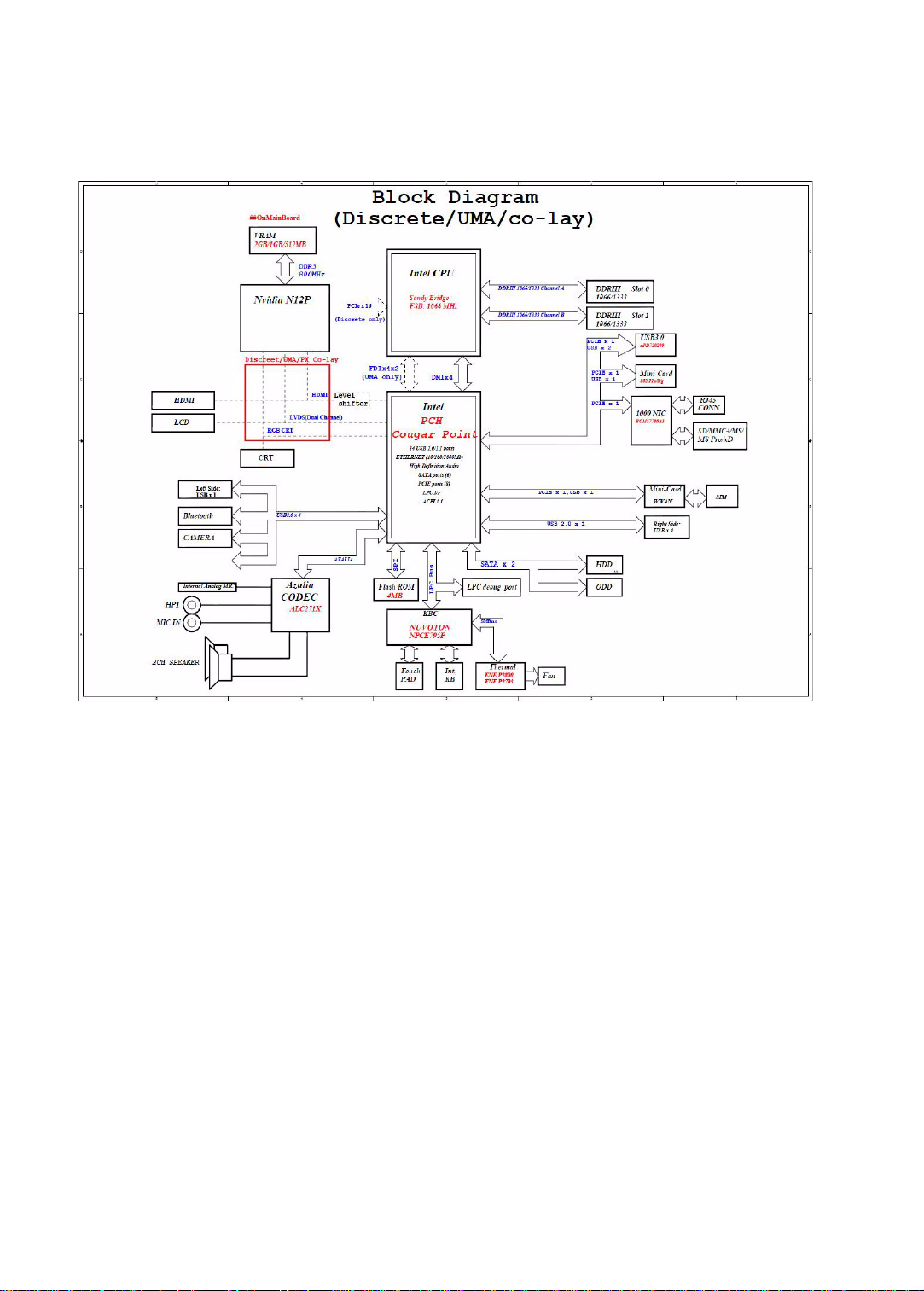
System block diagram
6
Page 13

www.packardbell.com
Hardware specifications and configurations
CPU
Item Specification
CPU type
Core logic Mobile Intel HM65 Express Chipset
Socket type LGA 1155
■
Intel Core i3 Processor: 2310M (2.1 GHz)
■
Intel Core i5 Processors: 2410M (2.3 GHz), 2520M (2.5 GHz), 2540M (2.6 GHz)
■
Intel Core i7 Processors: 2620M (2.7 GHz), 2630QM (2.0 GHz), 2720QM
(2.2 GHz), 2820QM (2.3 GHz)
Controllers
Item Controller
Core logic Mobile Intel HM65 Express Chipset
VGA
LAN Broadcom BCM57785X
USB 2.0 Mobile Intel HM65 Express Chipset
Bluetooth Foxconn Bluetooth ATH AR3011, BRM 2046 BT 2.1, BRM 2070 BT 2.1, BRM 2046
Wireless LAN
■
Discrete model: NVIDIA® N12P-GS or NVIDIA N12P-GV with DDR3-800 1 GB
or 2 GB VRAM
■
UMA model: Integrated in the Mobile Intel HM65 Express Chipset
BT3.0, BRM 2070 BT 3.0, or ATH BU12 BT 3.0
■
Foxconn Wirelss LAN Atheros HB95BG (HM) T77H121.10
■
Foxconn Wireless LAN Atheros HB97 2x2 BGN (HM)
■
Foxconn Wireless LAN Broadcomm 43225 2x2 BGN (HM) T77H103.00
■
Liteon Wireless LAN Atheris HB97 2x2 BGN (HM) WN6603AH
■
Liteon Wireless LAN Realtek 8192SE BGN WN6603LH (2x2 BGN)
■
Lan Intel WLAN TBD Taylor Peak 2x2 AGN
Memory card reader Alcor AU6433
Audio codec Realtek ALC272
BIOS
Item Specification
BIOS vendor Phoenix
BIOS version 1.02
7
Page 14

CHAPTER 1: System specifications
Item Specification
Supported protocols
■
Legacy BIOS and EFI architecture support
■
ACPI 3.0b compliance
■
PXE specification version 2.1
■
SMBIO Reference specification version 2.5 or later
■
USB specification revision 1.1/2.0/3.0
■
ASF specification version 2.0 or later
■
PCI Express base specification revision 2.1
■
PCI BIOS specification revision 2.1
■
BIOS Boot specification version 1.01
■
Simple boot flag specification version 2.1
■
System management bus specification version 2.0
■
AHCI support
■
Microsoft XP/Vista/Windows 7 logo program
■
Microsoft SLP 1.0 support
■
Microsoft OA 2.0/2.1 support
BIOS password control Manually set
Memory
Item Specification
Memory controller Built-in
Memory size 0 MB (no on-board memory)
SO-DIMM socket
number
2 sockets
Supports maximum
8GB
memory size
Supports SO-DIMM
DDR3 synchronous DRAM
type
Supports data rate 1066/1333 MT/s
Supports SO-DIMM
204-pin SO-DIMM
package
Memory module
combinations
Y ou can install memory modules in any combination as long as they match the above
specifications.
8
Page 15

Hard disk drive
Item Specification
www.packardbell.com
Models Seagate
Capacity (MB) 250000 320000 500000 640000 750000
Bytes per
sector
Data heads 4 4 4 4 4
Drive Format
Disks 2 2 2 2 2
Spindle speed
(RPM)
Performance Specifications
Buffer size
(MB)
Interface SATA SATA SATA SATA SATA
Max. media
transfer rate
(disk-buffer,
Mbytes/s)
ST9250315AS
Toshiba
MK2565GSX
HGST
HTS545025B9
A300
WD
WD2500BPVT22ZEST0
512 512 512 512 512
5400 5400 5400 5400 5400
8 8 8 8 8
100 MB/s
3
Seagate
ST9320310AS
Toshiba
MK3265GSX
HGST
HTS545032B9
A300/HTS5432
32A7A384
WD
WD3200BPVT22ZEST0
3.0 GB/s 3.0 GB/s 3.0 GB/s 3.0 GB/s
Seagate
ST9500325AS
Toshiba
MK5065GSX
HGST
HTS545050B9
A300
WD
WD5000BPVT22HXZT1
Toshiba
MK6465GSX
WD
WD6400BPVT22HXZT1
Seagate
ST9750423AS
Toshiba
MK7559GSX
HGST
HTS547575A9
E384
WD
WD7500BPVT22HXZT1
DC Power Requirements
Voltage
tolerance
5V (DC) ± 5% 5V (DC) ± 5% 5V (DC) ± 5% 5V (DC) ± 5% 5V (DC) ± 5%
Optical drive
Item Specification
Models HLDS Super-Multi Drive GT32N/GT34N
Performance Specification
Panasonic Super-Multi Drive UJ890A/UJ8A0
Pioneer Super-Multi Drive DVR-TD10RS
PLDS Super-Multi Drive DS-8A5SH
Sony Super-Multi Drive AD-7585H
Toshiba Super-Multi Drive TS-L633F
HLDS BD Combo CT30N
Panasonic UJ141AL
Pioneer BD Combo BDC-TD03RS
PLDS BD Combo DS-4E1S/DS-6E2SH
Sony BD Combo 4X BC-5540H
Panasonic BD RW UJ240A/UJ240AF
9
Page 16

Item Specification
CHAPTER 1: System specifications
Transfer rate
(KB/sec)
Sustained:
■
with CD: Max 3.6Mbytes/sec
■
with DVD: Max 10.08Mbytes/sec
Buffer Memory 2MB
Interface SATA
Applicable
disc format
CD: CD-DA, CD-ROM, CD-ROM XA, Photo CD (multi-session), Video CD, Cd-Extra (CD+),
CD-text
DVD: DVD-VIDEO, DVD-ROM, DVD-R (3.9GB, 4.7GB) DVD-R DL, DVD-RW, DVD-RAM,
DVD+R, DVD+R DL, DVD+RW
CD:
CD-DA (Red Book) - Standard Audio CD & CD-TEXT
CD-ROM (Yellow Book Mode1 & 2) - Standard Data
CD-ROM XA (Mode2 Form1 & 2) - Photo CD, Multi-Session
CD-I (Green Book, Mode2 Form1 & 2, Ready, Bridge)
CD-Extra/ CD-Plus (Blue Book) - Audio & Text/Video
Video-CD (White Book) - MPEG1 Video
CD-R (Orange Book Part)
CD-RW & HSRW (Orange Book Part Volume1 & Volume 2
Super Audio CD (SACD) Hybrid type
US & US+ RW
DVD:
DVD-ROM (Book 1.02), DVD-Dual
DVD-Video (Book 1.1)
DVD-R (Book 1.0, 3.9G)
DVD-R (Book 2.0, 4.7G) - General & Authoring
DVD+R (Version 1.0)
DVD+RW
DVD-RW (Non CPRM & CPRM)
DVD°”R Dual
Sustained:
■
with CD: Max 3.6Mbytes/sec
■
with DVD: Max 10.8Mbytes/sec
■
with BD: Max 11Mbytes/sec
■
for CD/DVD: 2MB
■
for BD: 4.5MB
Blu-Ray:
BD-R, BD-R DL, BD-RE, BD-RE DL
Loading
mechanism
Load: Manual
Release: (a) Electrical (Release Button), (b) ATAPI command, (c) Emergency
Power Requirement
Input Voltage 5 V ± 5% (Operating) 5 V ± 5% (Operating)
LCD
Item Specification
Vendor
Screen diagonal (mm) 14 inches
■
AUO
■
CMI
■
LG
■
Samsung
10
Page 17

www.packardbell.com
Item Specification
Resolution support (pixels)
■
2560 x 1600
■
1900x1200
■
1366 x 768
■
1360 x 768
■
1280 x 768
■
1280 x 720
■
1024 x 768
■
800 x 600
Pixel pitch 0.226
Pixel arrangement R.G.B. Vertical Stripe
Display mode
Typical white luminance
220 nits
(brightness)
Luminance uniformity 1.25 max.
Contrast ratio 400:1, 500:1 or 650:1
Response time (msec) 8
Nominal input voltage VDD +3.3V
Viewing angle (degree)
Horizontal: Right/Left
Vertical: Upper/Lower
45/45
20/45
Temperature range( C)
Operating
Storage (shipping)
0 to +50
-40 to +60
Keyboard
Item Specification
Keyboard controller Nuvoton NPCE795P
T otal number of keypads 86/87/91-key
Windows logo key Yes
Internal & external
Plug USB keyboard to the USB port directly
keyboard work
simultaneously
Pointing device
Item Specification
Type
Buttons Left/Right
■
Synaptics TM1465-001 Touchpad
■
ALPS KGDFF0508A Touchpad
11
Page 18

CHAPTER 1: System specifications
Memory card reader
Item Specification
Controller Alcor AU6433
Cards supported Support 5-in-1 card reader (MMC, MS, MS-pro, SD, and xD)
Compliancy
■
Complies to SDIO Host Interface Specification Rev 1.0
■
Supports MMC, MMCplus, SD Memory, and SDIO cards
■
SDIO Version 1.10 compliant with High-Speed Mode
■
SD Host Interface Specification v1.0
■
SD Host Interface Specification v2.0
■
SD HC (High Capacity SD memory card)
■
Supports SD memory card, with CPRM security
■
Complies to MultiMediaCard™ Version 4.0
■
Supports Memory Stick™ and MS PRO media cards
■
Supports xD-Picture™ card and SmartMedia™ cards
Audio
Item Specification
Audio codec Realtek ALC271X_VB3
Audio onboard or
Built-in
optional
Mono or stereo Stereo
Resolution 24-bit DAC and ADC
Compatibility HD Audi o
Sampling rate 192 kHz maximum sample rate
Internal microphone
Internal
2 speakers
speaker/quantity
Wired LAN
Item Specification
LAN chipset Broadcom BCM57785X
Supports LAN protocol 10/100/1000 Mbps
LAN connector type RJ45
LAN connector location Left side
Features
■
Integrated 10/10/1000 BASE-T transceiver
■
PCI v2.2 compliant
■
Wake on LAN support meeting ACPI requirements
12
Page 19

Bluetooth
Item Specification
www.packardbell.com
Chipset
■
Foxconn Bluetooth ATH AR3011
■
Foxconn Bluetooth BRM 2046 BT 2.1
■
Foxconn Bluetooth BRM 2070 BT 2.1
■
Foxconn Bluetooth BRM 2046 BT3.0
■
Foxconn Bluetooth BRM 2070 BT 3.0
■
Foxconn Bluetooth ATH BU12 BT 3.0
Data throughput 2.1 Mbit/s
Protocol Bluetooth 2.1/3.0
Interface USB (board level)
Connector type Wireless via Bluetooth protocols
Wireless LAN
Item Specification
Chipset
Data throughput 11~54 Mbps, up to 270 Mbps for Draft-N
Protocol
■
Foxconn Wirelss LAN Atheros HB95BG (HM) T77H121.10
■
Foxconn Wireless LAN Atheros HB97 2x2 BGN (HM)
■
Foxconn Wireless LAN Broadcomm 43225 2x2 BGN (HM) T77H103.00
■
Liteon Wireless LAN Atheris HB97 2x2 BGN (HM) WN6603AH
■
Liteon Wireless LAN Realtek 8192SE BGN WN6603LH (2x2 BGN)
■
Lan Intel WLAN TBD Taylor Peak 2x2 AGN
■
IEEE 802.11a
■
IEEE 802.11b
■
IEEE 802.11g
Interface PCI bus (mini PCI socket for wireless module)
USB
Item Specification
Chipset Mobile Intel HM65 Express Chipset
USB compliancy level 2.0
OHCI USB 3.0 host controller
Number of USB ports 3
Location
■
One on the right side
■
Two on the left side
13
Page 20

CHAPTER 1: System specifications
Buttons/Indicators/Ports
Item Specification
Buttons
Indicators
Ports
■
Power button
■
Bluetooth/Wireless network
■
Hard drive
■
Battery charge
■
Power
■
USB (three)
■
External display (VGA) port
■
Ethernet (RJ45)
■
Headphone/SPDIF Audio Out
■
Microphone in
■
DC in jack for AC adapter
■
5-in-1 card reader (SD™, MMC, MS, MS PRO, xD)
■
HDMI™ port with HDCP support
Camera
Item Specification
Model Chicony 1.3M CH9665SN, CH_6A1_SP
Interface USB 2.0
Resolution 1.3 MP (1280 x800)
LED
Liteon 1.3M LT9665AL/LT6AASP, LT6AASP( 09P2BF127), LT_6A1_SP
Suyin 1.3M SY9665SN, SY_6A1_SP
Fans
CPU temperature (° C) Fan speed (rpm) Acoustic level (dBA)
45-50 0-3000 29
55-66 0-3300 33
68-74 3300-3800 38
78-83 3800-4100 40
86-91 4100-4800 40
Throttling 50%: % is controlled by operating system. Temperature poi nt is 95 °C. OS sh ut down at 100 °C; H/W
shut down at 105 °C
14
Page 21

Battery
Item Specification
www.packardbell.com
Vendor
■
LGC
■
Panasonic
■
Samsung
■
Sanyo
■
Sony
■
Simplo
Type Li-ion
Pack capacity 4400mAH
Number of battery cell 6
Package configuration 3 cells in series, 2 series in parallel
Normal voltage 11.1V
Charge voltage 12.6V (max)
Power supply
Item Specification
Vendor
Input rating 90VAC to 264VAC, 47Hz to 63Hz
■
Chicony
■
Delta
■
Liteon
■
Hipro
Maximum input AC
1.7A (max)
current
Output rating 19V DC, 3.42A, 65W
15
Page 22

CHAPTER 1: System specifications
Power savings
ACPI mode Power Management
Mech. Off (G3) All devices in the notebook are turned off completely.
Soft Off (G2/S5) OS initiated shutdown. All devices in the n otebook are turned off completely.
Working (G0/S0) Individual devices such as the CPU and hard disc may be power managed in this
state.
Suspend to RAM (S3)
■
CPU set power down
■
VGA suspend
■
PCMCIA suspend
■
Audio power down
■
Hard drive power down
■
Optical drive power down
■
Super I/O low power mode
Save to Disk (S4) Also called Hibernation mode. System saves all system states and data onto the
disc prior to powering off the whole system.
16
Page 23

CHAPTER2
• BIOS setup utility
• BIOS recovery
• Clearing a BIOS password
• Unlocking the hard drive
System utilities
17
Page 24
CHAPTER 2: System utilities
Phoenix SecureCore Tiano Setup
CPU Type:
CPU Speed:
IDE0 Model Name:
I D E 0 S er ia l Nu mb er :
ATAPI Model Name:
System BIOS Version:
VGA BIOS Version:
KBC Version:
Serial Number:
Asset Tag Number:
Product Name:
Manufacturer Name:
UUID:
Intel (R) Core (TM) i7-2720QM CPU @ 2.20GHz
90JAC2YBT
O p t i ar c BD R OM
V1.02
2080
1.00
XXXXXXXXXXXXXXXXXXXXXXX
Base Board Asset Tag
XXXXXXXX
XXXXXXX
XXXXXXXX-XXXX-XXXX-XXXX-XXXXXXXXXXX
2.20GHz
TOSHIBA MK6465
F1
Esc
Help
Exit
Select Item
Select Menu
Change Values
Select Sub-Menu
F5/F6
Enter
F9
F10
Setup Defaults
S a v e a nd E xi t
Security Boot ExitMainInformation
BIOS setup utility
The BIOS setup utility is a hardware configuration program built into the notebook’s
BIOS (Basic Input/Output System). The notebook was shipped already properly
configured and optimized. However , if the user encounters configura tion problems,
you may need to run Setup.
To run the BIOS Setup Utility:
1 Turn on the notebook.
If the computer is already turned on, save your data and close all open
applications, then restart the computer.
2 Press F2 when the Press <F2> to enter Setup prompt appears on the bottom
of the screen.
Use the left and right arrow keys to move between selections on the menu
bar.
18
Page 25
www.packardbell.com
Navigating the BIOS setup utility
Use the keys listed in the legend bar on the bottom of the Setup screen to work
your way through the various menu and submenu screens.
To use the BIOS setup utility:
• To choose a menu, use the left and right arrow keys.
• To choose an item, use the up and down arrow k eys.
• To change the value of a parameter, press F5 or F6.
• A plus sign (+) indicates the item has sub-items. Press ENTER to expand this
item.
• To load default settings, press F9.
• To save changes made and close th e utility, press F10.
1 Press ESC while you are in any of the menu screen to display the Exit menu.
Important
• You can change the value of a parameter if it is enclosed in
square brackets.
• Navigation keys for a particular menu are shown on the bottom
of the screen. Help for parameters are found in the Item Specific
Help part of the screen. Read this information carefully when
making changes to parameter values.
• The screenshots used in this section are for illustration only. The
values displayed may not be the same as those in your computer.
BIOS setup utility menus
The Setup utility has five menus for configuring the various system functions.
These include: Information, Main, Security, Boot, and Exit.
Important
• The screenshots used in this section are for illustration only. The
values displayed may not be the same as those in your computer.
Actual screen information varies by model, installed features, and
location.
• In the descriptive table following each of the screenshot, settings
in boldface are the default settings.
19
Page 26
CHAPTER 2: System utilities
Phoenix SecureCore Tiano Setup
CPU Type:
CPU Speed:
IDE0 Model Name:
I D E 0 S e ri al N um be r:
ATAPI Model Name:
System BIOS Version:
VGA BIOS Version:
KBC Version:
Serial Number:
Asset Tag Number:
Product Name:
Manufacturer Name:
UUID:
Intel (R) Core (TM) i7-2720QM CPU @ 2.20GHz
90JAC2YBT
O p t i a rc B D RO M
V1.02
2080
1.00
XXXXXXXXXXXXXXXXXXXXXXX
Base Board Asset Tag
XXXXXXXX
XXXXXXX
XXXXXXXX-XXXX-XXXX-XXXX-XXXXXXXXXXX
2.20GHz
TOSHIBA MK6465
F1
Esc
Help
Exit
Select Item
Select Menu
Change Values
Select Sub-Menu
F5/F6
Enter
F9
F10
Setup Defaults
S a v e a n d Ex it
Security Boot ExitMainInformation
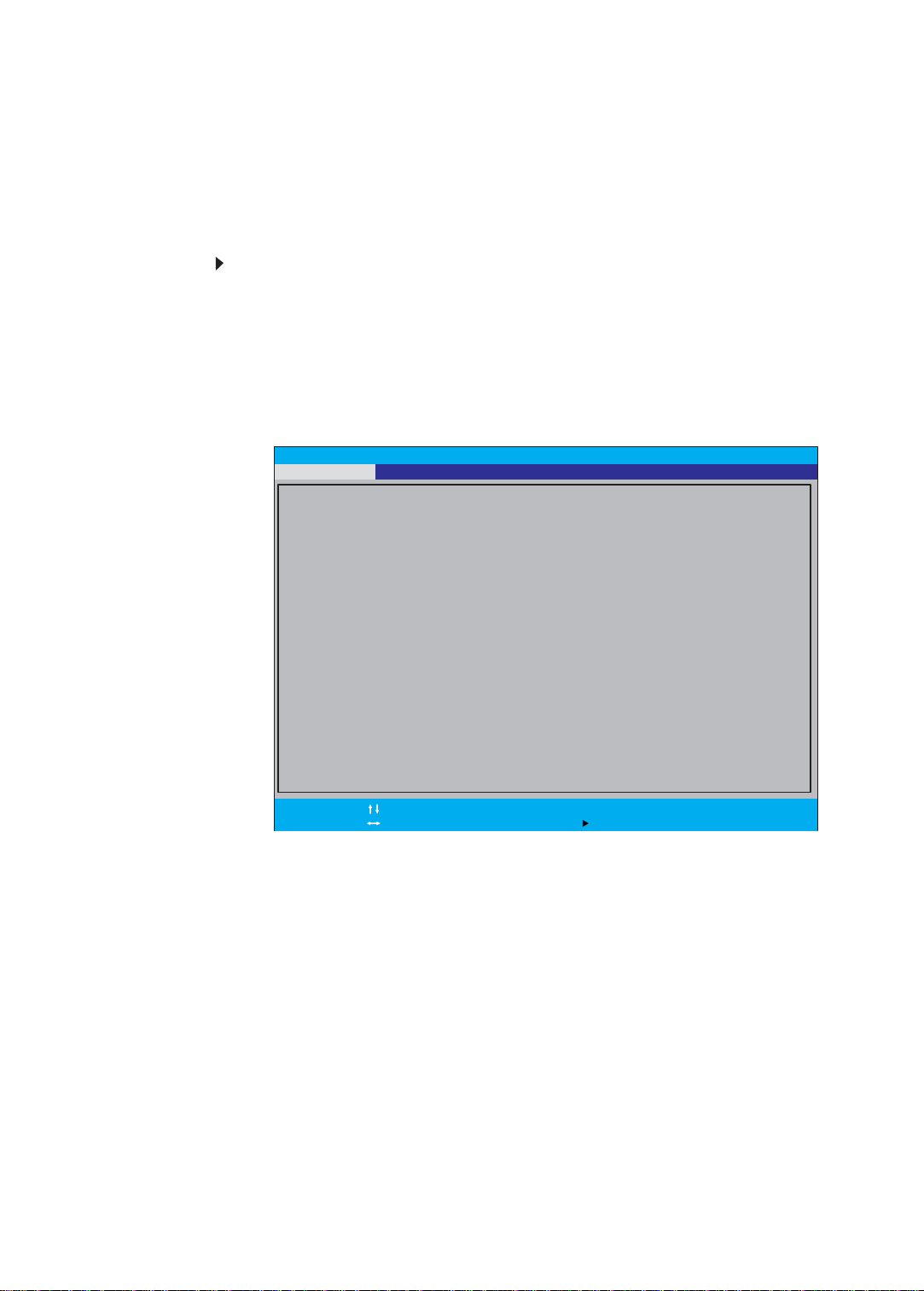
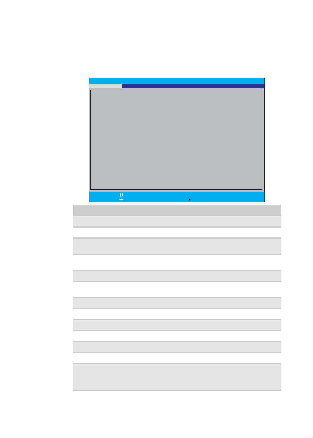
Information
The Information menu displays a summary of your computer hardware information.
These information are necessary for troubleshooting and may be required when
asking for technical support.
Parameter Description
CPU Type Displays the processor model and speed.
CPU Speed Displays the processor speed.
IDE0 Model Name Displays the model name of the hard drive installed on the
primary IDE master.
IDE0 Serial Number Displays the serial number of the hard drive installed on the
primary IDE master.
ATAPI Model Name Displays the model name of the installed optical drive.
System BIOS
Displays system BIOS version.
Version
VGA BIOS Version Displays the VGA firmwa re version.
KBC Version Displays the keyboard controller version.
Serial Number Displays the system serial number.
Asset Tag Number Displays the system asset tag number
Product Name Displays the official model name of the computer.
Manufacturer Name Displays the name of the computer manufacturer.
UUID Displays the computer ’s UUID (universally unique identifier).
UUID is an identifier standard used in software construction,
standardized by the Open Software Foundation (OSF) as part
of the Distributed Computing Environment (DCE).
20
Page 27
www.packardbell.com
Item Specific Help
V i e w o r s e t t h e s y s t e m
time.
System Time:
System Date:
Total Memory:
Video Memory:
Quiet Boot:
Network Boot:
F12 Boot Menu:
D2D Recovery:
SATA Mode:
F1
Esc
Help
Exit
Select Item
Select Menu
Change Values
Select Sub-Menu
F5/F6
Enter
F9
F10
Setup Defaults
S a v e a n d E x i t
[]
[11 ]
:05:48
/17/2010
8192 MB
2048 MB
[Enabled]
[Enabled]
[Disabled]
[Enabled]
[AHCI Mode]
10
Boot ExitMainInformation Security
Phoenix SecureCore Tiano Setup
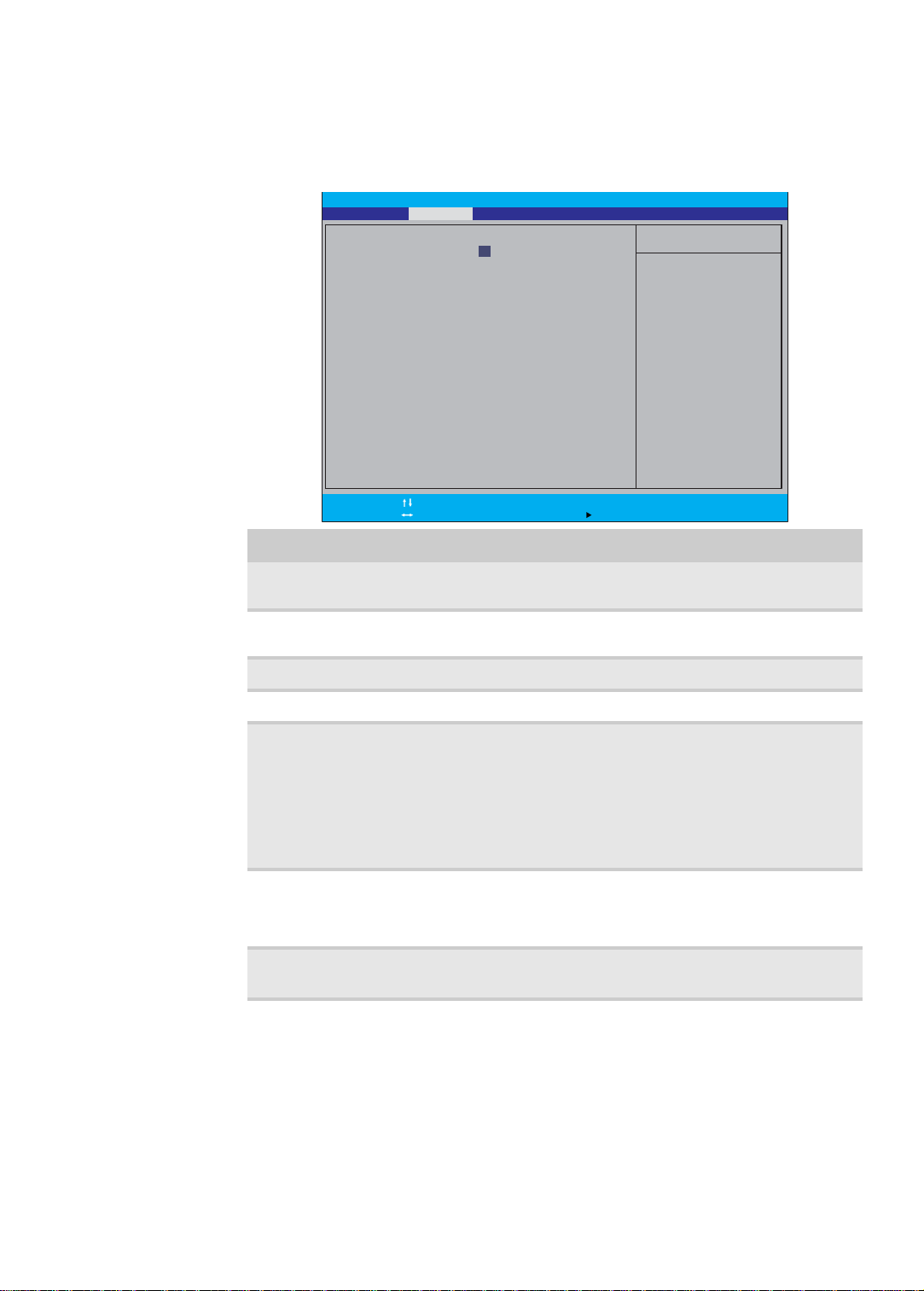
Main
Use the Main menu to set the system time and date, and other basic options.
Parameter Description Format/Options
System Time Displays the system time. The time is
System Date Displays the system date. MM/DD/YYYY
Total Memory Displays the size of system memory detecte d during boot-up.
Video Memory Displays the size of video memory detected during boot-up.
Quiet Boot Enables or disables the Quiet Boot
Network Boot When enabled, a remote host with
F12 Boot Menu Enables or disables the Boot menu during
expressed in a 24-hour format.
function.
When enabled, BIOS setup is in graphical
mode and displays only the computer
brand logo during POST and while booting.
When disabled, BIOS setup is in
conventional text mode and displays the
system Summary Screen.
appropriate boot image can boot this
computer. (only works with an Ethernet
device.)
POST.
HH:MM:SS
(hour:minute:second)
(month/day/year)
Disabled
Enabled
Disabled
Enabled
Disabled
Enabled
21
Page 28
CHAPTER 2: System utilities
Item Specific Help
Set or clear the
Supervisor account’s
password.
S u p e r v i s o r P a s s w or d Is :
U s e r P a s s w o r d I s :
H D D P a s s w o r d I s :
S e t U s e r P a s s w o r d
S e t H D D P a s s w o r d
P a s s w o r d o n B o o t :
Set Supervisor Password
F1
Esc
Help
Exit
Select Item
Select Menu
Change Values
Select Sub-Menu
F5/F6
Enter
F9
F10
Setup Defaults
S a v e a n d E x i t
Clear
Clear
Clear
[Enter]
[Enter]
[Disabled]
[]Enter
Boot ExitMainInformation Security
Phoenix SecureCore Tiano Setup
Parameter Description Format/Options
D2D Recovery Enables or disables the D2D Recovery
function. This function allows the user to
create a hidden partition on the hard drive
Disabled
Enabled
to store the operation system. User can
then use this partition to restore the system
to factory defaults by pressing the Alt+F10
keys during system boot-up.
SATA Mode Select the SAT A controller operating mode.
When set to AHCI (Advanced Host
AHCI Mode
IDE
Controller Interface), the SATA controller
enables its AHCI and RAID features when
the computer boots up.
When set to IDE, the SATA controller
disables its AHCI and RAID functions when
the computer boots up.
Note: If you do not intend to use the AHCI
or RAID features set this parameter to IDE
to speed up the boot-up time.
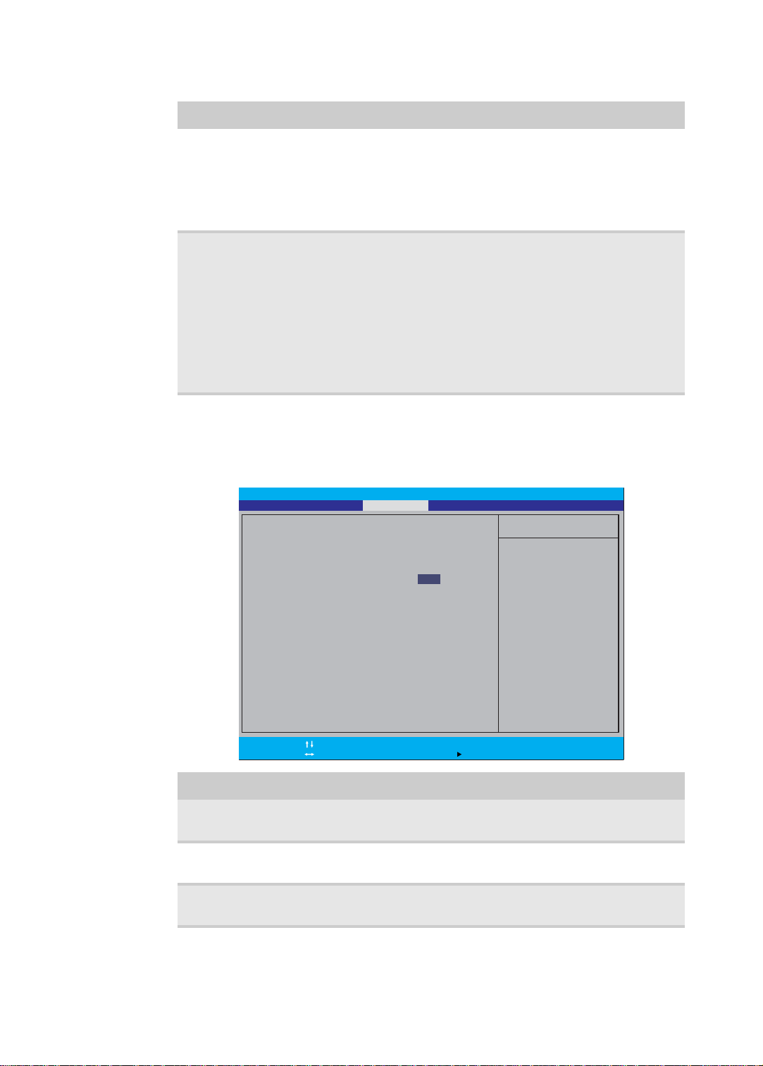
Security
Use the Security menu option to set system passwords to protect your computer
from unauthorized use.
.
22
Supervisor
Password Is
User Password Is Displays the user password status. Clear
HDD Password Is Displays the hard drive password status. Clear
Parameter Description Option
Displays the supervisor password status. Clear
Set
Set
Set
Page 29
www.packardbell.com
Parameter Description Option
Set Supervisor
Password
Set User Password Press Enter to set a user password. When set, this password will
Set HDD
Password
Password on Boot Referred to as the power-on password. When
Caution
When you are prompted to enter a password, you have three tries
before the system halts. Don’t forget your password.
Press Enter to set a supervisor password. When set, this password
will allow the user to access and change all settings in the Setup
Utility.
restrict a user’s access to the Setup menus. Only the following
menus will be accessible:
• System Time and System Date
• All Exit menu options excluding Load Setup Defaults
Note: A supervisor password must first be set before creating a
user password.
If Password on Boot is enabled, the user must enter the user
password each time the notebook is turned on or wakes from
Sleep.
Press Enter to set password for accessing the hard disk drive
(HDD) password. It will be required during boot-up or when waking
from hibernation mode.
enabled, the user or supervisor password will be
required to boot up the system.
Note: A supervis or password must first be set
before creating a user password.
Disabled
Enabled
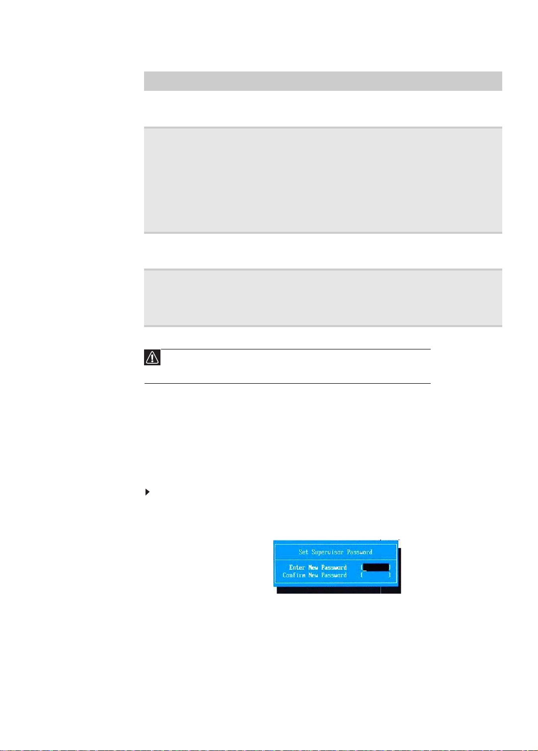
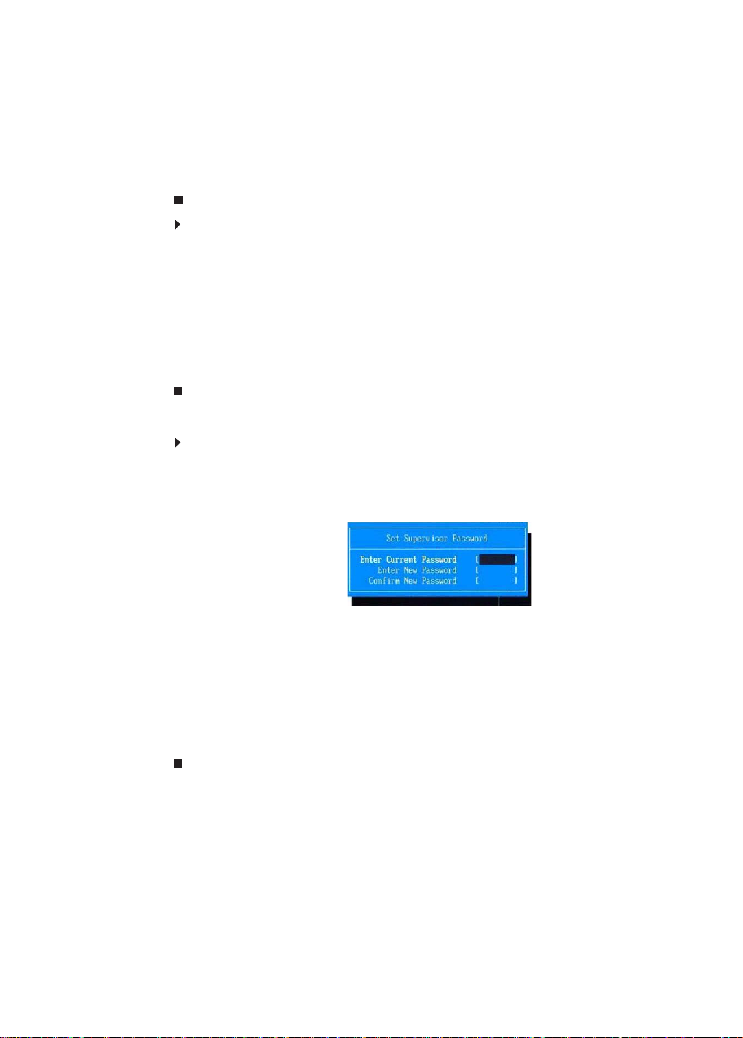
Setting a password
Note the following reminders before you define a system password:
• The maximum length of password contains 8 alphanumeric characters.
• System passwords are case-insensitive.
• When typing the password, only shaded blocks representing each typed
character are visible.
To set a supervisor password:
1 Press or to highlight Set Supervisor Password, then press Enter.
The Set Supervisor Passw ord box opens.
2 Type a password, then press Enter.
23
Page 30
CHAPTER 2: System utilities
3 Retype the password to verify the first entr y, then press Enter.
You will be prompted to save the new password.
4 Press Enter.
5 Press F10 to save the password and close the Setup Utility or you can
proceed to setting a user password.
To set a user password:
1 Press or to highlight Set User Password, then press Enter.
The Set User Password box opens.
2 Type a password, then press Enter.
3 Retype the password to verify the first entr y, then press Enter.
You will be prompted to save the new password.
4 Press Enter.
5 Press F10 to save the password and close the Setup Utility.
Changing a password
To change a password:
1 Press or to highlight the Set Supervisor Password or Set User Password
field, then press Enter.
The Set Supervisor Password or Set User Password box opens.
24
2 Type the current password, then press Enter.
3 Type a new password, then press Enter.
4 Retype the new password to verify the first entry, then press Enter.
You will be prompted to save the new password.
5 Press Enter.
6 Press F10 to save the password and close the Setup Utility or you can
proceed to setting a user password.
Page 31

www.packardbell.com
Removing a password
To remove a password:
1 Press or to highlight the Set Supervisor Password or Set User Password
field, then press Enter.
The Set Supervisor Passw ord or Set User Password box opens.
2 Type the current password, then press Enter.
3 Press Enter twice without entering anything in the new and confirm password
fields.
You will be prompted to confirm the password removal.
4 Press Enter.
5 Press F10 to save the password and close the Setup Utility or you can
proceed to setting a user password.
Resetting a password
If you have forgotten the user password, the computer will continue to function
normally but you will have limited access to the Setup utility.
If you have enabled the Password on Boot field and you forget the supervisor
password, you will not be able to boot up the computer. The same thing applies
if you forget the HDD password.
To clear a lost BIOS password (user or supervisor password) you need to short
the clear password hardware gap located on the system board. Go to page 30
for instructions.
To regain access to your computer if you lose the HDD password, you need to
generate a master password and unlock your hard drive. Go to page 31 for
instructions.
25
Page 32

CHAPTER 2: System utilities
Item Specific Help
U s e < > o r < > t o
select a device, then
p r e s s < F 6 > t o m o v e i t
u p t h e l i s t , o r < F 5 >
t o m o v e i t d o w n t h e
list. Press <Esc> to
escape the menu.
Boot Priority Order
F1
Esc
Help
Exit
Select Item
Select Menu
Change Values
Select Sub-Menu
F5/F6
Enter
F9
F10
Setup Defaults
S a v e a n d E x i t
2: IDE CD/DVD: Optiarc BD ROM BC-5540H
3: Network Boot: BRCM MBA Slot 0400 v14.4.3
4 : U S B H D D :
5 : U S B F D D :
6 : U S B C D / D V D :
1: IDE 0: TOSHIBA MK6465GSX
Boot ExitMainInformation Security
Phoenix SecureCore Tiano Setup
Boot
Use the Boot menu to set the preferred drive sequence in which the Setup utility
attempts to boot the operating system.
To set boot drive sequence:
1 Press or to highlight a bootable device.
2 Press F5 or F6 to move the selected device up or down the boot sequence.
3 Press F10 to save the changes you made and close the Setup utility.
26
Page 33

www.packardbell.com
Main
Item Specific Help
Equal to F10, save all
changes of all menus,
then exit setup configure
driver. Finally resets the
system automatically.
F1
Esc
Help
Exit
Select Item
Select Menu
Change Values
Select Sub-Menu
F5/F6
Enter
F9
F10
Setup Defaults
S a v e a n d E x i t
Information
Exit Discarding Changes
Load Setup Defaults
Discard Changes
Save Changes
Exit Saving Changes
Boot ExitSecurity
Phoenix SecureCore Tiano Setup
Exit
The Exit menu screen lists options for quitting from the Setup Utility.
Option Description
Exit Saving Changes Saves changes made and closes the Setup utility. Keyboard
shortcut: F10
Exit Discarding
Discards changes made and closes the Setup utility.
Changes
Load Setup Defaults Loads the factory-default settings for all Setup parameters.
Keyboard shortcut: F9
Discard Changes Discards all changes made to the Setup utility and loads
previous configuration settings.
Save Changes Saves all changes made to the Setup utility.
27
Page 34

CHAPTER 2: System utilities
BIOS recovery
An interruption during a BIOS flash procedure (e.g. a power outage) can corrupt
the BIOS code, which will cause the system to go into an unbootable state. You
need to access and execute the boot block program to reboot the computer and
recover the regular BIOS code.
Caution
Observe the following when performing a BIOS recovery:
• Make sure the battery pack is installed to the system and that
the computer is connected to a UPS unit during the BIOS
recovery and BIOS flash procedures.
• The BIOS crisis recovery disk should be prepared in a computer
running the Windows XP or Windows Vista OS.
Creating the Crisis Recovery disk
To create the Crisis Recovery disk:
1 Prepare a removable USB storage device with a capacity size greater than
10 MB .
Note that all data on the USB storage device will be cleared during the
creation of the crisis disk.
2 Set up a computer running the Windows XP or Windows Vista OS and plug
in the USB storage device into an available USB port.
3 Use the text editor to create a file named startup.nsh with the following
contents.
fs0:
PFlash.efi/bb1/silent/sv/sd JV40009j.fd (where JV40009j.fd is the new BIOS
image file)
4 Copy the startup.nsh file and the following folder and files to the USB storage
device.
– EFI folder
– BIOS.cap
– PFlash.efi
– CrisisRevocery.efi
– BIOS image file
5 Eject and reconnect the USB storage device, and make sure the files are
saved to the device.
Performing a BIOS recovery
To perform a BIOS recovery:
1 Shut down the BIOS failed-computer.
2 Connect the USB storage device containing the Crisis Recovery disk files
to the failed computer.
3 Press and hold the Fn+Esc keys (this is the BIOS recovery hotkey), then
press the power button.
The BIOS recovery process begins. When the process is complete the
computer will automatically reboot.
28
Page 35

4 Disconnect the USB storage device from the computer.
5 Perform a BIOS flash procedure to update the BIOS firmware.
Running the Flash utility:
To run the Flash utility:
1 Rename the BIOS file as “XXXXXXX.FD”.
2 Copy the “XXXXXXX.FD” file to a bootable USB device containing the Crisis
Recovery disk files.
3 Turn off the computer.
4 Insert the USB device containing the renamed BIOS file and the Crisis
Recovery disk files to any USB port.
5 Press and hold the Fn+Esc keys (this is the BIOS recov ery hotkey), then
press the power button.
6 Release the Fn+Esc keys after POST.
www.packardbell.com
29
Page 36

CHAPTER 2: System utilities
Clearing a BIOS password
To clear a lost BIOS password (user or supervisor password) you need to short
the clear password hardware gap (G2201) located on the system board.
Gap Default setting Function
G2201 Open (normal) Short to clear the user and supervisor
To clear a BIOS password:
passwords.
1 Turn off the notebook and unplug all the peripherals connected to it.
2 Complete the steps in “Removing the battery” on page 38.
3 Complete the steps in “Removing the bay cover” on page 39.
4 Remove the wireless card by perf orming steps 3 – 7 of the “Replacing the
wireless card” on page 43.
5 Locate the G2201 gap.
6 Use an electrical conductivity tool to short the two contact s on the har dware
gap together.
7 While resting the tool on the two contacts, plug one end of the AC adapter
into the DC power jack and plug one end to an electrical outlet.
8 Press the power button to turn on the system.
9 After the POST, remove the tool from the hardware gap.
10 Reinstall the battery pack, and the bay cover.
11 Turn on the notebook and press F2 during bootup to access the Setup utility.
12 Press F9 to load the system defaults.
13 Press F10 to save the changes you made and close the Setup utility.
30
Page 37

www.packardbell.com
Unlocking the hard drive
To regain access to your computer if you lose the HDD password, you need to
generate a master password and unlock the hard drive.
To unlock a hard drive:
1 Open the computer in a DOS environment.
2 Type the following command:
A\> unlock6 XXXXX 00 (where XXXXX is the HDD password error code)
3 Press Enter to display the command options.
4 Select option 2 (upper case ASCII code), then press Enter.
5 Write down the generated master password.
6 Reboot the computer.
7 In the HDD password prompt, type the master password generated in step 5,
then press
Enter.
31
Page 38

CHAPTER 2: System utilities
32
Page 39

CHAPTER3
Replacing notebook components
• Preventing static electricity
discharge
• Preparing the work space
• Required tools
• Preparing the notebook
• Removing the battery
• Replacing the hard drive
• Replacing the wireless card
• Adding or replacing memory
modules
• Replacing the optical drive
• Replacing the palm rest
module
• Replacing the touchpad board
• Replacing the keyboard
• Replacing the speakers
• Replacing the power button
board
• Replacing the USB board
• Replacing the Bluetooth
module
• Replacing the system board
• Replacing the cooling
assembly
• Replacing the processor
• Replacing the LCD panel
assembly
• Replacing the LCD front panel
• Replacing the webcam
• Replacing the LCD panel
• Replacing the LCD panel
hinge brackets
• Replacing the microphone
• Replacing the antennas
• Replacing the LCD assembly
lid
33
Page 40

CHAPTER 3: Replacing notebook components
Preventing static electricity discharge
Warning
To avoid exposure to dangerous electrical voltages and moving
parts, turn off your notebook, remove the battery, and unplug the
power cord and network cable before opening the case.
Warning
To prevent risk of electric shock, do not insert any object into the
vent holes of the notebook.
Important
Before performing maintenance on the notebook, you shoul d read
and understand the information in this section.
The components inside your notebook are ex tre mely sensitive to st atic e lectricity,
also known as electrostatic discharge (ESD).
Before performing maintenance on the notebook, follow these guidelines:
• Avoid static-causing surfaces such as carpeted floors, plastic, and packing
foam.
• Remove components from their antistatic bags only when you are ready to
use them. Do not lay components on the outside of antistatic bags because
only the inside of the bags provide electrostatic protection.
• Always hold components by their edges. Avoid touching the edge
connectors. Never slide components over any surface.
• Wear a grounding wrist strap (available at most electronics stores) and att ach
it to a bare metal part of your workbench or other grounded connection.
• Touch a bare metal surface on your workbench or other grounded object.
Tape
34
Some of the procedures in this guide involve removing tape that secures cables
or components. Two types of tape are used in this notebook:
• Mylar, non-conductive tape is typically transparent, with a red or brown tint.
• Conductive tape is typically grey or silver in color.
If the existing tape cannot be reused, replace it with the same type. Make sure
the replacement tape is of the non-ESD generating kind. Do not use cellophane
tape.
Page 41

www.packardbell.com
Preparing the work space
Before performing maintenance on the notebook, make sure that your work space
and the notebook are correctly prepared.
• Wear a grounding (ESD) wrist strap, a nd use a grounded or dissip ative work
mat.
• Use a sturdy table. Make sure that the t able top is wide e nough to hold each
component as you remove it.
• Ensure that clear lighting condition is available to make part identification
easier.
• Keep your work surface free from clutter and debris that may damage
components.
• Use a magnetized screwdriver for removing screws.
• When removing components that are attached to the notebook by a cable,
unplug the cable before removing the screws, when possible, to avoid
damaging the cable.
• As you remove components and screws, lay them toward the rear of your
work surface (behind the notebook) or far enough to the side that your arms
will not accidentally brush them onto the floor.
• To help keep track of screws, try the following:
– Place each component’s screws in their own section of a parts sorter.
– Place each component’s screws next to the component on your work
surface.
– Print the first page of each task, then place the page toward the rear of
your work surface. As you remove screws, place the screws in their
respective section on the page.
– After loosening screws that are deeply recessed in a hole (for example,
on the bottom of the base assembly), you can leave the screws in the
holes if you place small pieces of masking tape over the hole openings.
When reassembling the component, just remove the tape and tighten
the screws.
– When you place flat-headed screws on the work surface, stand them
on their heads to prevent the screws from rolling off the table.
35
Page 42

CHAPTER 3: Replacing notebook components
Required tools
To disassemble the notebook, you need the following tools:
• Wrist grounding strap (for ESD prevention)
v
• Flat screwdriver
• Conductive mat (for ESD prevention)
v
• Phillips screwdriver
v
• Non-marring plastic scribe
v
36
Page 43

www.packardbell.com
Preparing the notebook
To prepare the notebook for maintenance:
1 Make sure that the optical disc drive is empty.
2 Turn off the notebook.
3 Close the LCD panel.
4 Disconnect the AC adapter.
5 Disconnect the network cable and all peripheral devices connected to the
notebook.
6 Make sure there is no memory card on the card reader slot. To remove a
memory card:
a Push against the card, as if you were pushing it further into the slot,
letting the card spring out
b Pull the memory card out of its slot.
37
Page 44

CHAPTER 3: Replacing notebook components
Removing the battery
To remove the battery:
1 Turn the notebook over so the base is facing up.
2 Slide the battery release latch.
3 Remove the battery out of the notebook.
Note
The battery is highlighted with a yellow rectangle in the above
image. Follow local regulations for battery disposal.
38
Page 45

www.packardbell.com
Phillips #0 screwdriver
Non-marring plastic scribe
Removing the bay cover
To remove or replace components located on the lower bay, you need to remove
the bay cover first.
Tools you need to complete this task:
Screws removed during this task:
• 3 black M2.5×6 (bay cover)
To remove the bay cover:
1 Complete the steps in “Preparing the notebook” on page 37.
2 Turn the notebook over so the base is facing up.
3 Remove the bay cover screws.
39
Page 46

CHAPTER 3: Replacing notebook components
4 Insert a non-marring plastic scribe on the cover’s notch to release the co ver
from the computer, and then remove the cover.
40
Page 47

www.packardbell.com
Phillips #0 screwdriver
Non-marring plastic scribe
Replacing the hard drive
Tools you need to complete this task:
Screws removed during this task:
• 3 black M2.5×6 (bay cover)
• 1 black M2×3 (hard drive)
• 2 chrome M3×4 (hard drive bracket)
To replace the hard drive:
1 Complete the steps in “Preparing the notebook” on page 37.
2 Complete the steps in “Removing the bay cover” on page 39.
3 Remove the hard drive screw.
41
Page 48

CHAPTER 3: Replacing notebook components
4 Grasp the black mylar tab and use it to disengage the hard drive from its
connector, and then remove the drive from its compartment.
5 If your new hard drive already includes the hard drive bracket, go to step 8.
If you need to use the bracket from the old hard drive, go to step 6.
6 Remove the screws that secure the hard drive bracket, and then deta ch the
drive from the bracket.
42
7 Place the bracket on the new drive and secure it with the two screws
removed in step 6.
8 Slide the new hard drive into the hard drive compartment and make sure
it’s properly engaged to the SATA1 connector.
9 Secure the new drive to the base with the screw removed in step 6.
10 Reinstall the bay cover.
Page 49

www.packardbell.com
Phillips #0 screwdriver
Non-marring plastic scribe
Replacing the wireless card
Tools you need to complete this task:
Screws removed during this task:
• 3 black M2.5×6 (bay cover)
• 1 black M2×3 (wireless card)
To replace the wireless card:
1 Complete the steps in “Preparing the notebook” on page 37.
2 Complete the steps in “Removing the bay cover” on page 39.
3 Detach the barcode sticker.
4 Unplug the antenna cables. Note which color cable corresponds to each of
the connectors.
Important
The number of antenna cables varies depending on the type
of wireless card installed on the notebook. IEEE 802.11n
cards typically have three antenna cables. Other types of
wireless cards usually have only two antenna cables.
5 Move the antenna cables away from the wireless card screw.
43
Page 50

CHAPTER 3: Replacing notebook components
6 Remove the screw securing the wireless card.
7 Pull the card out of the slot.
44
8 Insert the new wireless card at a 30° angle into the empty Mini Card slot.
The card is keyed so it can only be inserted in one direction. If the car d does
not fit, make sure that the notch in the c ard lin es up with t he tab in the card
slot.
9 Secure the new wireless card with the screw removed in step 6.
10 Reconnect the antenna cables to the connectors.
11 Reinstall the bay cover.
Page 51

www.packardbell.com
Phillips #0 screwdriver
Non-marring plastic scribe
Adding or replacing memory modules
Important
Use only memory modules designed for this notebook.
Tools you need to complete this task:
Screws removed during this task:
• 3 black M2.5×6 (bay cover)
To add or replace memory modules:
1 Complete the steps in “Preparing the notebook” on page 37.
2 Complete the steps in “Removing the bay cover” on page 39.
3 If you are replacing a memory modu le, go to step 4.
If you installing an additional memory module, go to step 5.
4 Use a non-marring plastic scribe to push out the latches on both sides of
the memory slot until the module tilts upward (1), and then remove the
memory module from its slot (2).
5 Insert the new memory module at a 30° angle into an empty memory slot,
and then press it down until it clicks into place.
The module is keyed so it can only be inse rted in one direction. If the module
does not fit, make sure that the notch in the module lines up with the tab in
the memory slot.
6 Reinstall the bay cover.
45
Page 52

CHAPTER 3: Replacing notebook components
Phillips #0 screwdriver
Non-marring plastic scribe
Replacing the optical drive
Tools you need to complete this task:
Screws removed during this task:
• 1 black M2.5×6 (o ptical drive)
• 1 black M2×3 (optical drive bracke t)
To replace the optical drive:
1 Complete the steps in “Preparing the notebook” on page 37.
2 Complete the steps in “Removing the battery” on page 38.
3 Remove the optical drive screw.
46
4 Use the non-marring plastic scribe to carefully push the optical drive out of
the drive bay (1), and then slide the drive out (2).
Page 53

www.packardbell.com
5 If your new optical drive already has it’s own bracket and be zel, go to step 10.
If you need to use the bezel and bracket from the old optical drive, perform
steps 6 – 9 as necessary.
6 Detach the bezel from the old optical drive.
7 Remove the screw that secures the optical drive bracket, and then detach
the bracket from the drive.
8 Attach the bezel to the new optical drive.
9 Attach the bracket to the new optical drive and secure it with the screw
removed in step 7.
10 Slide the new optical drive into the drive bay and make sure it’s properly
engaged to the ODD1 connector.
11 Secure the new drive to the system board with the screw removed in step 3.
12 Reinstall the battery.
47
Page 54

CHAPTER 3: Replacing notebook components
Phillips #0 screwdriver
Flat screwdriver or Non-marring plastic scribe
Replacing the palm rest module
Tools you need to complete this task:
Screws removed during this task:
• 3 black M2.5×6 (bay cover)
• 1 black M2×3 (hard drive)
• 1 black M2.5×6 (optical drive)
• 9 black M2.5×6 (palm rest - base side)
To replace the palm rest:
1 Complete the steps in “Preparing the notebook” on page 37.
2 Complete the steps in “Removing the battery” on page 38.
3 Complete the steps in “Removing the bay cover” on page 39.
4 Remove the hard drive screw, and then remove the hard drive from its
compartment.
48
5 If the notebook has a wireless card installed, unplug the antenna cables.
Page 55

www.packardbell.com
6 Release the antenna cables from its latches.
7 Remove the optical drive screw, and then remove the optical drive.
8 Remove the screws securing the palm rest on the base side.
49
Page 56

CHAPTER 3: Replacing notebook components
9 Locate the small gaps on the bottom side of the palm rest and insert a small
flat-blade screwdriver or non-marring scribe into each gap to separate the
palm rest from the base enclosure.
10 Once the bottom side is separated, pry loose the left and right sides of the
palm rest, until all the palm rest retaining tabs have been released.
11 Flip the palm rest module over (1) .
12 Unlock the touchpad cable connector (2) and remove the touchpad cable (3).
13 Lift the palm rest module from the base enclosure (4).
14 Reconnect the touchpad cable to its system board connector.
15 Place the new palm rest assembly on top of t he base enclosure an d press
it down on all sides until it snaps into place.
16 Close the LCD panel and turn the notebook over so the base is facing up.
17 Secure the palm rest assembly with the screws removed in step 8.
18 Reinstall the optical drive by performing steps 10 and 11 of the “Replacing
the optical drive” procedure on page 46.
19 Reinstall the hard drive by performing steps 8 and 9 of the “Replacing th e
hard drive” procedure on page 41.
20 If you have disconnected any wireless antennas, reconnect them now.
21 Reinstall the bay cover.
22 Reinstall the battery.
50
Page 57

www.packardbell.com
Phillips #0 screwdriver
Flat screwdriver or Non-marring plastic scribe
Replacing the touchpad board
Tools you need to complete this task:
Screws removed during this task:
• 3 black M2.5×6 (bay cover)
• 1 black M2×3 (hard drive)
• 1 black M2.5×6 (optical drive)
• 9 black M2.5×6 (palm rest - base side) -
Indicated by A in step 8 of the “Replacing the palm rest module” procedure
on page 48
To replace the touchpad board:
1 Complete the steps in “Preparing the notebook” on page 37.
2 Complete the steps in “Removing the battery” on page 38.
3 Remove the hard drive by performi ng steps 3 and 4 of the “Replacing the
hard drive” procedure on page 41.
4 Remove the optical drive by performing steps 3 and 4 of the “Replacing the
optical drive” procedure on page 46.
5 Remove the palm rest by performing steps 8 – 13 of the “Replacing the palm
rest module” procedure on page 48.
6 Note the orientation of the touchpad board for later reference in installing
the new touchpad board.
7 Insert a small flat-blade screwdriver or non-marring scribe between the
touchpad board and the palm rest’s underside, and carefully pry the board
loose.
8 Remove the touchpad board from the palm rest.
51
Page 58

CHAPTER 3: Replacing notebook components
Note
A circuit board that is >10 cm2 has been highlighted with a yellow
rectangle as shown in the above image. Follow the local regulations
for disposing this type of circuit board.
9 Observing the same orientation as the old touchpad board, secure the new
board on the palm rest.
10 Cover the new touchpad board with the double-sided tape.
11 Insert the touchpad cable to the touchpad board cable connector, and then
close the clip to lock the cable in place.
12 Reinstall the palm rest module by performing steps 14 – 17 of the “Replacing
the palm rest module” procedure on page 48.
13 Reinstall the optical drive by performing steps 10 and 11 of the “Replacing
the optical drive” procedure on page 46.
14 Reinstall the hard drive by performing steps 8 and 9 of the “Replacing th e
hard drive” procedure on page 41.
15 If you have disconnected any wireless antennas, reconnect them now.
16 Reinstall the bay cover.
17 Reinstall the battery.
52
Page 59

www.packardbell.com
Phillips #0 screwdriver
Flat screwdriver or Non-marring plastic scribe
Replacing the keyboard
Tools you need to complete this task:
Screws removed during this task:
• 3 black M2.5×6 (bay cover)
• 1 black M2×3 (hard drive)
• 1 black M2.5×6 (optical drive)
• 5 black M2×3 (keyboard frame - top base side) - Indicated
by A in step 8)
• 13 black M2.5×6 (keyboard
frame/palm rest module - base side) - indicated by B in step 8)
• 12 black M2×2 (k eyboard
frame) - indicated by A in step 16)
• 10 black M1.4×3 (keyboard frame) -
indicated by B in step 16)
To replace the keyboard:
1 Complete the steps in “Preparing the notebook” on page 37.
Caution
The keyboard is connected to the notebook through the keyboard
cable. Disconnect this cable first before pulling th e keyboard aw ay
from the palm rest.
2 Complete the steps in “Removing the battery” on page 38.
3 Complete the steps in “Removing the bay cover” on page 39.
53
Page 60

CHAPTER 3: Replacing notebook components
4 Remove the hard drive screw, and then remove the hard drive from its
compartment.
5 If the notebook has a wireless card installed, unplug the antenna cables.
6 Release the antenna cables from the latches securing them.
54
7 Remove the optical drive screw, and then remove the optical drive.
Page 61

www.packardbell.com
8 Remove the screws securing the palm rest and keyboard frame to the base
side.
9 Remove the palm rest by performing steps 9 – 13 of the “Replacing the palm
rest module” procedure on page 48.
10 Locate the small gaps on the top side of the keyboard frame and insert a
small flat-blade screwdriver or non-marring scribe into each gap to sepa rate
the keyboard frame from the base enclosure.
11 Once the top side is separated, pry loose the left and right sides of the
keyboard frame, until all the retaining tabs have been released.
12 Flip the keyboard over to access to the keyboard cable (1).
13 Unlock the system board’s keyboard cable connector (2), and then remove
the cable (3).
55
Page 62

CHAPTER 3: Replacing notebook components
14 Unlock the system board’s power button board cable connector, and then
remove the cable.
15 Lay the keyboard frame down.
16 Remove the screws securing the keyboard.
56
17 Lift the keyboard from the frame.
Page 63

www.packardbell.com
18 If your new keyboard already includes the keyboard frame, go to step 21.
If you need to use the keyboard frame from the old keyboard, go to step 19.
19 Position the new keyboard on the keyboard frame.
20 Secure the keyboard with the screws removed in step 16.
21 Lay the keyboard down and insert the keyboard cable to its system board
connector, and then close the clip to lock the cable in place.
Important
The keyboard cable is correctly oriented if it is not twisted.
22 Flip the keyboard over and press it down on all sides until it snaps into place.
23 Close the LCD panel and turn the notebook over so the base is facing up.
24 Secure the keyboard frame with the screws removed in step 8.
25 Reinstall the palm rest module by performing steps 14 – 17 of the “Replacing
the palm rest module” procedure on page 48.
26 Reinstall the optical drive by performing steps 10 and 11 of the “Replacing
the optical drive” procedure on page 46.
27 Reinstall the hard drive by performing steps 8 and 9 of the “Replacing the
hard drive” procedure on page 41.
28 If you have disconnected any wireless antennas, reconnect them now.
29 Reinstall the bay cover.
30 Reinstall the battery.
57
Page 64

CHAPTER 3: Replacing notebook components
Phillips #0 screwdriver
Flat screwdriver or Non-marring plastic scribe
Replacing the speakers
Tools you need to complete this task:
Screws removed during this task:
• 3 black M2.5×6 (bay cover)
• 1 black M2×3 (hard drive)
• 1 black M2.5×6 (optical drive)
• 5 black M2×3 (keyboard frame - top base side) - Indicated
by A in step 8 of the “R eplacing the keyboard” procedure on page 53
• 13 black M2.5×6 (keyboard
frame/palm rest module - base side) - indicated by B in step 8 of the
“Replacing the keyboard” procedure on page 53
• 4 black M2×3 (speakers)
To replace the speakers:
1 Complete the steps in “Preparing the notebook” on page 37.
2 Remove the hard drive by perf orming steps 3 and 4 of the “Replacing the
hard drive” procedure on page 41.
3 Remove the optical drive by performing steps 3 and 4 of the “Replacing the
optical drive” procedure on page 46.
4 Remove the palm rest by performing steps 8 – 13 of the “Replacing the palm
rest module” procedure on page 48.
5 Remove the keyboard by performing steps 10 – 14 of the “R eplacing the
keyboard” procedure on page 53..
Caution
The keyboard is connected to the notebook through a keyboard
cable. Disconnect this cable first before pulling the keyboard away
from the palm rest assembly.
6 Lay the keyboard frame keys down.
58
Page 65

www.packardbell.com
7 Detach the mylar tape covering the speaker cable, and then release the
speaker cable from the latches securing the cable.
8 Disconnect the speaker cable fr om the power button board.
9 Remove the speaker screws, and then remove the speakers.
10 Position the new speakers on the keyboard frame.
11 Secure the speakers with the screws removed in step 9.
12 Reconnect the speaker cable to the power button board.
13 Secure the speaker cable on the keyboard frame latches.
14 Cover the speaker cable with mylar tape.
15 Reinstall the keyboard by perform ing steps 21 – 24 of the “Replacing the
keyboard” procedure on page 53.
16 Reinstall the palm rest module by performing steps 14 – 17 of the “Replacing
the palm rest module” procedure on page 48.
17 Reinstall the optical drive by performing steps 10 and 11 of the “Replacing
the optical drive” procedure on page 46.
18 Reinstall the hard drive by performing steps 8 and 9 of the “Replacing the
hard drive” procedure on page 41.
59
Page 66

CHAPTER 3: Replacing notebook components
19 If you have disconnected any wireless antennas, reconnect them now.
20 Reinstall the bay cover.
21 Reinstall the battery.
60
Page 67

www.packardbell.com
Phillips #0 screwdriver
Flat screwdriver or Non-marring plastic scribe
Replacing the power button board
Tools you need to complete this task:
Screws removed during this task:
• 3 black M2.5×6 (bay cover)
• 1 black M2×3 (hard drive)
• 1 black M2.5×6 (optical drive)
• 5 black M2×3 (keyboard frame - top base side) - Indicated
by A in step 8 of the “Replacing the keyboard” procedure on page 53
• 13 black M2.5×6 (keyboard
frame/palm rest module - base side) - indicated by B in step 8 of the
“Replacing the keyboard” procedure on page53
• 2 black M2×3 (power button board)
To replace the power button board:
1 Complete the steps in “Preparing the notebook” on page 37.
2 Complete the steps in “Removing the battery” on page 38.
3 Remove the hard drive by performing steps 3 and 4 of the “Replacing the
hard drive” procedure on page 41.
4 Remove the optical drive by performing steps 3 and 4 of the “Replacing the
optical drive” procedure on page 46.
5 Remove the palm rest by performing steps 8 – 13 of the “Replacing the palm
rest module” procedure on page 48.
6 Remove the keyboard by performing steps 10 – 14 of the “Replacing the
keyboard” procedure on page 53..
Caution
The keyboard is connected to the notebook through a keyboa rd
cable. Disconnect this cable first before pulling th e keyboard aw ay
from the palm rest assembly.
7 Lay the keyboard frame keys down.
61
Page 68

CHAPTER 3: Replacing notebook components
8 Disconnect the speaker cable from the power board.
9 Unlock the power button board cable connector (1), and then remove the
cable (2).
10 Remove the power button board screw, and then remove the old power
button board from the keyboar d frame.
11 Position the new power button board on the keyboard frame.
12 Secure the power button board with the screw removed in step 10.
13 Insert the power button cable to the power button board cable connector,
and then close the clip to lock the cable in place.
14 Reinstall the keyboard by performing steps 21 – 24 of the “Rep lacing the
keyboard” procedure on page 53.
15 Reinstall the palm rest module by performing steps 14 – 17 of the “Replacing
the palm rest module” procedure on page 48.
16 Reinstall the optical drive by performing steps 10 and 11 of the “Replacing
the optical drive” procedure on page 46.
17 Reinstall the hard drive by performing steps 8 and 9 of the “Replacing th e
hard drive” procedure on page 41.
18 If you have disconnected any wireless antennas, reconnect them now.
19 Reinstall the bay cover.
20 Reinstall the battery.
62
Page 69

www.packardbell.com
Phillips #0 screwdriver
Flat screwdriver or Non-marring plastic scribe
Replacing the USB board
Tools you need to complete this task:
Screws removed during this task:
• 3 black M2.5×6 (bay cover)
• 1 black M2×3 (hard drive)
• 1 black M2.5×6 (optical drive)
• 9 black M2.5×6 (palm rest - base side) -
Indicated by A in step 8 of the “Replacing the palm rest module” procedure
on page 48
To replace the USB board:
1 Complete the steps in “Preparing the notebook” on page 37.
2 Complete the steps in “Removing the battery” on page 38.
3 Remove the hard drive by performi ng steps 3 and 4 of the “Replacing the
hard drive” procedure on page 41.
4 Remove the optical drive by performing steps 3 and 4 of the “Replacing the
optical drive” procedure on page 46.
5 Remove the palm rest by performing steps 8 – 13 of the “Replacing the palm
rest module” procedure on page 48.
6 Unlock the two USB board cable connectors (1), and then remove the USB
board cables (2).
63
Page 70

CHAPTER 3: Replacing notebook components
7 Remove the USB board from the tabs securing it.
8 Place the new USB board in the base enclosure.
9 Reconnect the two USB board cables to the new USB board.
10 Reinstall the keyboard by performing steps 21 – 24 of the “Rep lacing the
keyboard” procedure on page 53.
11 Reinstall the palm rest module by performing steps 14 – 17 of the “Replacing
the palm rest module” procedure on page 48.
12 Reinstall the optical drive by performing steps 10 and 11 of the “Replacing
the optical drive” procedure on page 46.
13 Reinstall the hard drive by performing steps 8 and 9 of the “Replacing the
hard drive” procedure on page 41.
14 If you have disconnected any wireless antennas, reconnect them now.
15 Reinstall the bay cover.
16 Reinstall the battery.
64
Page 71

www.packardbell.com
Phillips #0 screwdriver
Flat screwdriver or Non-marring plastic scribe
Replacing the Bluetooth module
Tools you need to complete this task:
Screws removed during this task:
• 3 black M2.5×6 (bay cover)
• 1 black M2×3 (hard drive)
• 1 black M2.5×6 (optical drive)
• 9 black M2.5×6 (palm rest - base side) -
Indicated by A in step 8 of the “Replacing the palm rest module” procedure
on page 48
To replace the Bluetooth module:
1 Complete the steps in “Preparing the notebook” on page 37.
2 Complete the steps in “Removing the battery” on page 38.
3 Remove the hard drive by performi ng steps 3 and 4 of the “Replacing the
hard drive” procedure on page 41.
4 Remove the optical drive by performing steps 3 and 4 of the “Replacing the
optical drive” procedure on page 46.
5 Remove the palm rest by performing steps 8 – 13 of the “Replacing the palm
rest module” procedure on page 48.
6 Disconnect the Bluetooth cable from its system board connector (1), and then
detach the Bluetooth module (2).
7 Place the new Bluetooth module on the system board and reconnect the
Bluetooth cable to its system board connector.
8 Reinstall the keyboard by perform ing steps 21 – 24 of the “Replacing the
keyboard” procedure on page 53.
65
Page 72

CHAPTER 3: Replacing notebook components
9 Reinstall the palm rest module by performing steps 14 – 17 of the “Replacing
the palm rest module” procedure on page 48.
10 Reinstall the optical drive by performing steps 10 and 11 of the “Replacing
the optical drive” procedure on page 46.
11 Reinstall the hard drive by performing steps 8 and 9 of the “Replacing the
hard drive” procedure on page 41.
12 If you have disconnected any wireless antennas, reconnect them now.
13 Reinstall the bay cover.
14 Reinstall the battery.
66
Page 73

www.packardbell.com
Phillips #0 screwdriver
Flat screwdriver or Non-marring plastic scribe
Replacing the system board
Tools you need to complete this task:
Screws removed during this task:
• 3 black M2.5×6 (bay cover)
• 1 black M2×3 (hard drive)
• 1 black M2.5×6 (optical drive)
• 5 black M2×3 (keyboard frame - top base side) - Indicated
by A in step 8 of the “Replacing the keyboard” procedure on page 53
• 13 black M2.5×6 (keyboard
frame/palm rest module - base side) - indicated by B in step 8 of the
“Replacing the keyboard” procedure on page53
• 1 black M2×3 (system board)
To replace the system board:
1 Complete the steps in “Preparing the notebook” on page 37.
2 Complete the steps in “Removing the battery” on page 38.
3 Remove the memory from the old system board and install it on the new
system board by following the instructions in the “Adding or replacing
memory modules” section on page 45.
4 If the notebook has a wireless card installed, remove the card from the old
system board and install it on the new system board by following the
instructions in the “Replacing the wireless card” section on page 43.
5 Remove the hard drive by performi ng steps 3 and 4 of the “Replacing the
hard drive” procedure on page 41.
6 Remove the optical drive by performing steps 3 and 4 of the “Replacing the
optical drive” procedure on page 46.
7 Remove the palm rest by performing steps 8 – 13 of the “Replacing the palm
rest module” procedure on page 48.
8 Remove the keyboard by performing steps 10 – 14 of the “Replacing the
keyboard” procedure on page 53.
Caution
The keyboard is connected to the notebook through a keyboa rd
cable. Disconnect this cable first before pulling th e keyboard aw ay
from the palm rest assembly.
67
Page 74

CHAPTER 3: Replacing notebook components
9 Remove USB board by performing steps 6 and 7 of the “Replacing the USB
board” procedure on page 63.
10 Remove the Bluetooth module by performing step 6 of the “Replacing the
Bluetooth module” procedure on page 65.
11 Unlock the two USB board cable connectors (1), and then remove the USB
board cables from their system board connectors (2).
12 Disconnect the LCD cable from its system board connector.
13 Remove the system board screw.
Note
A circuit board that is >10 cm2 has been highlighted with a yellow
rectangle as shown in the previous image. Follow the local
regulations for disposing this type of circuit board.
The RTC battery has been highlighted with a yellow box in the
previous image. Detach the RTC battery and follow the local
regulations for disposing it.
68
Page 75

www.packardbell.com
UMA modelDiscrete model
14 Carefully pull the system board out of the base enclosure, and then flip it
over (1).
15 Disconnect the DC-input cable from its system board connector (2), and then
remove the system board (3).
16 Remove the cooling assembly by performing steps 4 – 7 of the “Replacing
the cooling assembly” procedure on page 70.
17 If your new system board does not include a processor, remove the
processor from the old system board and install it on the new system board
by performing steps 5 and 6 in the “Replacing the processor” section on
page 73.
18 Reinstall the cooling assembly by performing steps 8 – 11 of the “Replacing
the cooling assembly” procedure on page 70.
19 Place the new system board in the base enclosure and secure it with the
screw removed in step 13.
20 Reconnect the DC-input, LCD and USB board cables to their system board
connectors.
21 Reinstall the USB board by performing steps 8 – 9 of the “Replacing the
USB board” procedure on page 63.
22 Reinstall the Bluetooth module by performing step 7 of the “Replacing the
Bluetooth module” procedure on page 65.
23 Reinstall the keyboard by perform ing steps 21 – 24 of the “Replacing the
keyboard” procedure on page 53.
24 Reinstall the palm rest module by performing steps 14 – 17 of the “Replacing
the palm rest module” procedure on page 48.
25 Reinstall the optical drive by performing steps 10 and 11 of the “Replacing
the optical drive” procedure on page 46.
26 Reinstall the hard drive by performing steps 8 and 9 of the “Replacing the
hard drive” procedure on page 41.
27 If you have disconnected any wireless antennas, reconnect them now.
28 Reinstall the bay cover.
29 Reinstall the battery.
69
Page 76

CHAPTER 3: Replacing notebook components
Phillips #0 screwdriver
Flat screwdriver or Non-marring plastic scribe
UMA modelDiscrete model
Replacing the cooling assembly
Tools you need to complete this task:
Additional materials you need to complete this task:
• Soft cloth and isopropyl alcohol; or alcohol pad
• Thermal grease
Screws removed during this task:
• 3 black M2.5×6 (bay cover)
• 1 black M2×3 (hard drive)
• 1 black M2.5×6 (optical drive)
• 5 black M2×3 (keyboard frame - top base side) - Indicated
by A in step 8 of the “R eplacing the keyboard” procedure on page 53
• 13 black M2.5×6 (keyboard
frame/palm rest module - base side) - indicated by B in step 8 of the
“Replacing the keyboard” procedure on page 53
• 1 black M2×3 (system board)
To replace the cooling assembly:
1 Complete the steps in “Preparing the notebook” on page 37.
2 Remove the system board by performing steps 1 – 15 of the “Replacing the
system board” procedure on page 67.
3 Turn the system board over to access the cooling fan cable.
4 Disconnect the cooling fan cable from its system board connector.
70
Page 77

www.packardbell.com
UMA modelDiscrete model
UMA modelDiscrete model
5 Loosen the spring-loaded captive screws securing the cooling assembly.
Follow the screw sequence indicated on the below images.
6 Remove the cooling assembly from the system board.
7 Lay the cooling assembly down in an upright position to avoid tainting your
work space with thermal grease.
8 Moisten a soft cloth with isopropyl alcohol and clean the processor die to
remove any thermal grease residue. Wipe the die surface several times to
make sure that no particles or dust contaminants are evident. Allow the
alcohol to evaporate before continuing.
Caution
Do not touch the contact surface of the new cooling assembly nor
the processor dire as this may leave dead skin cells or oils from
your finger that can result in poor thermal grease performance.
9 Apply just enough thermal grease to evenly coat the surface of th e processor
die.
10 Place the new cooling assembly on the system boar d and ti ghten it s captive
screws to secure it in place. Follow the sequence of the number beside each
screw when securing the cooling assembly.
71
Page 78

CHAPTER 3: Replacing notebook components
11 Reconnect the cooling fan cable to its system board connector.
12 Reconnect the DC input cable to its system board connector.
13 Reinstall the system board by performing steps 19 and 20 of the “Replacing
the system board” procedure on page 67.
14 Reconnect the LCD, USB board and Bluetooth module cables to their system
board connectors.
15 Reinstall the Bluetooth module by performing step 7 of the “Replac ing the
Bluetooth module” procedure on page 65.
16 Reinstall the USB board by performing steps 8 – 9 of the “Replacing th e
USB board” procedure on page 63.
17 Reinstall the keyboard by performing steps 21 – 24 of the “Rep lacing the
keyboard” procedure on page 53.
18 Reinstall the palm rest module by performing steps 14 – 17 of the “Replacing
the palm rest module” procedure on page 48.
19 Reinstall the optical drive by performing steps 10 and 11 of the “Replacing
the optical drive” procedure on page 46.
20 Reinstall the hard drive by performing steps 8 and 9 of the “Replacing th e
hard drive” procedure on page 41.
21 If you have disconnected any wireless antennas, reconnect them now.
22 Reinstall the bay cover.
23 Reinstall the battery.
72
Page 79

www.packardbell.com
Phillips #0 screwdriver
Flat screwdriver Non-marring plastic scri be
Replacing the processor
Tools you need to complete this task:
Additional materials you need to complete this task:
• Soft cloth and isopropyl alcohol; or alcohol pad
• Thermal grease
Screws removed during this task:
• 3 black M2.5×6 (bay cover)
• 1 black M2×3 (hard drive)
• 1 black M2.5×6 (optical drive)
• 5 black M2×3 (keyboard frame - top base side) - Indicated
by A in step 8 of the “Replacing the keyboard” procedure on page 53
• 13 black M2.5×6 (keyboard
frame/palm rest module - base side) - indicated by B in step 8 of the
“Replacing the keyboard” procedure on page53
• 1 black M2×3 (system board)
To replace the processor:
1 Complete the steps in “Preparing the notebook” on page 37.
2 Remove the system board by performing steps 1 – 15 of the “Replacing the
system board” procedure on page 67.
3 Remove the cooling assembly by performing steps 4 – 7 of the “Replacing
the cooling assembly” procedure on page 70.
4 Remove the barcode sticker on top of the processor.
73
Page 80

CHAPTER 3: Replacing notebook components
5 Use a flat-blade screwdriver to turn t he processor lock screw
counter-clockwise (1).
6 Remove the old processor from the system board (2).
7 Align pin 1 of the new processor (indicated by the gold arrow on the corner
of the processor) with the beveled corner of the processor socket.
The processor will easily fit into the socket if you oriented it properly.
74
8 Use a flat-blade screwdriver to turn the lock screw 180° clockwise to secure
the processor in place.
9 Apply just enough thermal grease to evenly coat the surface of the p rocessor
die.
10 Reinstall the cooling assembly by performing steps 10 – 11 of the “Replacing
the cooling assembly” procedure on page 70.
11 Reinstall the system board by performing steps 19 and 20 of the “Replacing
the system board” procedure on page 67.
12 Reconnect the LCD, USB board and Bluetooth module cables to their system
board connectors.
13 Reinstall the Bluetooth module by performing step 7 of the “Replac ing the
Bluetooth module” procedure on page 65.
14 Reinstall the USB board by performing steps 8 – 9 of the “Replacing th e
USB board” procedure on page 63.
15 Reinstall the keyboard by performing steps 21 – 24 of the “Rep lacing the
keyboard” procedure on page 53.
16 Reinstall the palm rest module by performing steps 14 – 17 of the “Replacing
the palm rest module” procedure on page 48.
Page 81

www.packardbell.com
17 Reinstall the optical drive by performing steps 10 and 11 of the “Replacing
the optical drive” procedure on page 46.
18 Reinstall the hard drive by performing steps 8 and 9 of the “Replacing the
hard drive” procedure on page 41.
19 If you have disconnected any wireless antennas, reconnect them now.
20 Reinstall the bay cover.
21 Reinstall the battery.
75
Page 82

CHAPTER 3: Replacing notebook components
Phillips #0 screwdriver
Flat screwdriver or Non-marring plastic scribe
Replacing the LCD panel assembly
Tools you need to complete this task:
Screws removed during this task:
• 3 black M2.5×6 (bay cover)
• 1 black M2×3 (hard drive)
• 1 black M2.5×6 (optical drive)
• 5 black M2×3 (keyboard frame - top base side) - Indicated
by A in step 8 of the “R eplacing the keyboard” procedure on page 53
• 13 black M2.5×6 (keyboard
frame/palm rest module - base side) - indicated by B in step 8 of the
“Replacing the keyboard” procedure on page 53
• 1 black M2×3 (system board)
• 4 black M2.5×6 (LCD panel hinges)
To replace the LCD panel assembly:
1 Complete the steps in “Preparing the notebook” on page 37.
2 If the notebook has a wireless card installed, complete the steps in
“Removing the bay cover” on page 39, and then unplug the antenna cables.
If there’s no wireless card installed, proceed to step 3.
3 Remove the hard drive by perf orming steps 3 and 4 of th e “Replacing the
hard drive” procedure on page 41.
4 Remove the optical drive by performing steps 3 and 4 of the “Replacing the
optical drive” procedure on page 46.
5 Remove the palm rest by performing steps 8 – 13 of the “Replacing the palm
rest module” procedure on page 48.
6 Remove the keyboard by performing steps 10 – 14 of the “R eplacing the
keyboard” procedure on page 53.
Caution
The keyboard is connected to the notebook through a keyboard
cable. Disconnect this cable first before pulling the keyboard away
from the palm rest assembly.
7 Remove the system board by performing steps 1 – 15 of the “Replacing the
system board” procedure on page 67.
76
Page 83

www.packardbell.com
8 If the notebook has a wireless card installed, note the antenn a cable routing
for later reference and then perform step 9 to release the antenna cables
from the palm rest.
9 Release the antenna cables from the adhesive tabs and latches securing
them.
10 Carefully open the LCD panel to its fully extended position.
11 Remove the LCD hinge screws securing the LCD assembly.
12 Lift the LCD panel assembly up and away from the notebook.
77
Page 84

CHAPTER 3: Replacing notebook components
13 Position the new LCD panel assembly on the notebook, and then secure it
with the hinge screws removed in step 11.
14 If the notebook has a wireless card installed, proceed to step 15 to arrange
the antenna cables.
15 Refer to the antenna cable routing note made on step 9 and secure the
antenna cables to the base enclosure before pulling the ends downward to
the wireless card compartment.
16 Reinstall the system board by performing steps 19 and 20 of the “Replacing
the system board” procedure on page 67.
17 Reinstall the keyboard by performing steps 21 – 24 of the “Rep lacing the
keyboard” procedure on page 53.
18 Reinstall the palm rest module by performing steps 14 – 17 of the “Replacing
the palm rest module” procedure on page 48.
19 Reinstall the optical drive by performing steps 10 and 11 of the “Replacing
the optical drive” procedure on page 46.
20 Reinstall the hard drive by performing steps 8 and 9 of the “Replacing the
hard drive” procedure on page 41.
21 If you have disconnected any wireless antennas, reconnect them now.
22 Reinstall the bay cover.
23 Reinstall the battery.
78
Page 85

www.packardbell.com
Phillips #0 screwdriver
Flat screwdriver or Non-marring plastic scribe
Replacing the LCD front panel
Tools you need to complete this task:
Screws removed during this task:
• 3 black M2.5×6 (bay cover)
• 1 black M2×3 (hard drive)
• 1 black M2.5×6 (optical drive)
• 5 black M2×3 (keyboard frame - top base side) - Indicated
by A in step 8 of the “Replacing the keyboard” procedure on page 53
• 13 black M2.5×6 (keyboard
frame/palm rest module - base side) - indicated by B in step 8 of the
“Replacing the keyboard” procedure on page53
• 1 black M2×3 (system board)
• 4 black M2.5×6 (LCD panel hinges)
• 2 black M2.5×5 (LCD front panel)
To replace the LCD front panel:
1 Complete the steps in “Preparing the notebook” on page 37.
2 Remove the LCD panel assembly by perform ing steps 2 – 12 of the
“Replacing the LCD panel assembly” procedure on page 76.
3 Remove the screw covers from the corner of the LCD front panel.
79
Page 86

CHAPTER 3: Replacing notebook components
4 Remove the LCD front panel screws.
5 Carefully pry loose the front panel from the LCD assembly lid. Start on the
bottom side, continue to the left and right sides, and finally the top side.
Remove the front panel.
80
6 Place the new front panel on top of the LCD assembly lid.
Make sure that the LCD, webcam, microphone, and antenna cables are
properly routed on the hinge sides.
7 Press the front panel on all sides until it snaps into place.
Make sure that there is no gap between the front panel and the LCD
assembly lid.
8 Secure the front panel with screws removed in step 4.
9 Return the LCD front panel screw covers to their places.
10 Reinstall the LCD panel assembly by following the steps 13 – 15 of the
“Replacing the LCD panel assembly” procedure on page 76.
11 Reinstall the system board by performing steps 19 and 20 of the “Replacing
the system board” procedure on page 67.
12 Reinstall the keyboard by performing steps 21 – 24 of the “Rep lacing the
keyboard” procedure on page 53.
13 Reinstall the palm rest module by performing steps 14 – 17 of the “Replacing
the palm rest module” procedure on page 48.
14 Reinstall the optical drive by performing steps 10 and 11 of the “Replacing
the optical drive” procedure on page 46.
15 Reinstall the hard drive by performing steps 8 and 9 of the “Replacing th e
hard drive” procedure on page 41.
Page 87

www.packardbell.com
16 If you have disconnected any wireless antennas, reconnect them now.
17 Reinstall the bay cover.
18 Reinstall the battery.
81
Page 88

CHAPTER 3: Replacing notebook components
Phillips #0 screwdriver
Flat screwdriver or Non-marring plastic scribe
Replacing the webcam
Tools you need to complete this task:
Screws removed during this task:
• 3 black M2.5×6 (bay cover)
• 1 black M2×3 (hard drive)
• 1 black M2.5×6 (optical drive)
• 5 black M2×3 (keyboard frame - top base side) - Indicated
by A in step 8 of the “R eplacing the keyboard” procedure on page 53
• 13 b lack M2.5×6 (keyboard
frame/palm rest module - base side) - indicated by B in step 8 of the
“Replacing the keyboard” procedure on page 53
• 1 black M2×3 (system board)
• 4 black M2.5×6 (LCD panel hinges)
• 2 black M2.5×5 (LCD front panel)
To replace the webcam:
1 Complete the steps in “Preparing the notebook” on page 37.
2 Remove the LCD panel assembly by performing steps 2 – 12 of the
“Replacing the LCD panel assembly” procedure on page 76.
3 Remove the LCD front panel by performing steps 3 – 5 of the “Replacing
the LCD front panel” procedure on page 79.
4 Disconnect the webcam cable (1), and then pry the board from the LCD
assembly lid (2).
82
Page 89

www.packardbell.com
5 Place the new webcam on the top side of the LCD assembly lid.
6 Reconnect the webcam cable to its board connector.
7 Reinstall the LCD front panel by performing steps 6 – 9 of the “Replacing
the LCD front panel” procedure on page 79.
Make sure the webcam lens is aligned with camera peephole on the LCD
front panel before you secure the panel in place.
8 Reinstall the LCD panel assembly by following the steps 13 – 15 of the
“Replacing the LCD panel assembly” procedure on page 76.
9 Reinstall the system board by performing steps 19 and 20 of the “Replacing
the system board” procedure on page 67.
10 Reinstall the keyboard by perform ing steps 21 – 24 of the “Replacing the
keyboard” procedure on page 53.
11 Reinstall the palm rest module by performing steps 14 – 17 of the “Replacing
the palm rest module” procedure on page 48.
12 Reinstall the optical drive by performing steps 10 and 11 of the “Replacing
the optical drive” procedure on page 46.
13 Reinstall the hard drive by performing steps 8 and 9 of the “Replacing the
hard drive” procedure on page 41.
14 If you have disconnected any wireless antennas, reconnect them now.
15 Reinstall the bay cover.
16 Reinstall the battery.
83
Page 90

CHAPTER 3: Replacing notebook components
Phillips #0 screwdriver
Flat screwdriver or Non-marring plastic scribe
Replacing the LCD panel
Tools you need to complete this task:
Screws removed during this task:
• 3 black M2.5×6 (bay cover)
• 1 black M2×3 (hard drive)
• 1 black M2.5×6 (optical drive)
• 5 black M2×3 (keyboard frame - top base side) - Indicated
by A in step 8 of the “R eplacing the keyboard” procedure on page 53
• 13 b lack M2.5×6 (keyboard
frame/palm rest module - base side) - indicated by B in step 8 of the
“Replacing the keyboard” procedure on page 53
• 1 black M2×3 (system board)
• 4 black M2.5×6 (LCD panel hinges)
• 2 black M2.5×5 (LCD front panel)
• 4 chrome M2.5×4 (LCD panel)
To replace the LCD panel:
1 Complete the steps in “Preparing the notebook” on page 37.
2 Remove the LCD panel assembly by performing steps 2 – 12 of the
“Replacing the LCD panel assembly” procedure on page 76.
3 Remove the LCD front panel by performing steps 3 – 5 of the “Replacing
the LCD front panel” procedure on page 79.
4 Disconnect the webcam cable (1), and then pry the board from the LCD
assembly lid (2).
84
Page 91
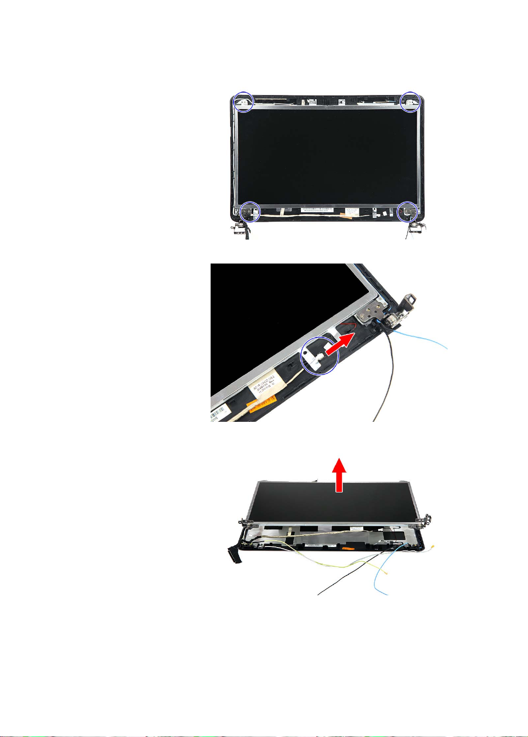
www.packardbell.com
5 Remove the LCD panel bracket screws.
6 Disconnect the microphone cable.
7 Remove the LCD panel from the LCD assembly lid.
8 Turn the LCD on its front to access the LCD-webcam cable.
85
Page 92

CHAPTER 3: Replacing notebook components
9 Detach the LCD-webcam cable from the LCD’s underside.
10 Disconnect the LCD-webcam cable from the LCD PCB.
86
11 Attach the LCD panel brackets and the LCD-webcam cable to the ne w LCD.
12 Place the new LCD panel on the LCD assembly lid.
13 Reconnect the microphone cable.
14 Secure the new LCD panel with the screws removed in step 5.
15 Reinstall the LCD front panel by performing steps 6 – 9 of the “Replacing
the LCD front panel” procedure on page 79.
Make sure the webcam lens is aligned with camera peephole on the LCD
front panel before you secure the panel in place.
16 Reinstall the LCD panel assembly by following the steps 13 – 15 of the
“Replacing the LCD panel assembly” procedure on page 76.
17 Reinstall the system board by performing steps 19 and 20 of the “Replacing
the system board” procedure on page 67.
18 Reinstall the keyboard by performing steps 21 – 24 of the “Rep lacing the
keyboard” procedure on page 53.
19 Reinstall the palm rest module by performing steps 14 – 17 of the “Replacing
the palm rest module” procedure on page 48.
20 Reinstall the optical drive by performing steps 10 and 11 of the “Replacing
the optical drive” procedure on page 46.
Page 93

www.packardbell.com
21 Reinstall the hard drive by performing steps 8 and 9 of the “Replacing the
hard drive” procedure on page 41.
22 If you have disconnected any wireless antennas, reconnect them now.
23 Reinstall the bay cover.
24 Reinstall the battery.
87
Page 94

CHAPTER 3: Replacing notebook components
Phillips #0 screwdriver
Flat screwdriver or Non-marring plastic scribe
Replacing the LCD panel hinge brackets
Tools you need to complete this task:
Screws removed during this task:
• 3 black M2.5×6 (bay cover)
• 1 black M2×3 (hard drive)
• 1 black M2.5×6 (optical drive)
• 5 black M2×3 (keyboard frame - top base side) - Indicated
by A in step 8 of the “R eplacing the keyboard” procedure on page 53
• 13 b lack M2.5×6 (keyboard
frame/palm rest module - base side) - indicated by B in step 8 of the
“Replacing the keyboard” procedure on page 53
• 1 black M2×3 (system board)
• 4 black M2.5×6 (LCD panel hinges)
• 2 black M2.5×5 (LCD front panel)
• 4 chrome M2.5×4 (LCD panel)
• 4 chrome M2×3 (LCD panel hinge brackets)
To replace the LCD:
1 Complete the steps in “Preparing the notebook” on page 37.
2 Remove the LCD panel assembly by performing steps 2 – 12 of the
“Replacing the LCD panel assembly” procedure on page 76.
3 Remove the LCD front panel by performing steps 3 – 5 of the “Replacing
the LCD front panel” procedure on page 79.
4 Remove the LCD panel by performing steps 4 – 7 of the “Replacing the LCD
panel” procedure on page 84.
88
Page 95

www.packardbell.com
5 Remove the screws securing the LCD panel brackets.
6 Attach the new LCD panel brackets to the LCD.
7 Reinstall the LCD panel by performing steps 11 – 14 of the “Replacing the
LCD panel” procedure on page 84.
8 Reinstall the LCD front panel by performing steps 6 – 9 of the “Replacing
the LCD front panel” procedure on page 79.
Make sure the webcam lens is aligned with camera peephole on the LCD
front panel before you secure the panel in place.
9 Reinstall the LCD panel assembly by following the steps 13 – 15 of the
“Replacing the LCD panel assembly” procedure on page 76.
10 Reinstall the system board by performing steps 19 and 20 of the “Replacing
the system board” procedure on page 67.
11 Reinstall t he keyboard by performing steps 21 – 24 of the “Replacing the
keyboard” procedure on page 53.
12 Reinstall the palm rest module by performing steps 14 – 17 of the “Replacing
the palm rest module” procedure on page 48.
13 Reinstall the optical drive by performing steps 10 and 11 of the “Replacing
the optical drive” procedure on page 46.
14 Reinstall the hard drive by performing steps 8 and 9 of the “Replacing the
hard drive” procedure on page 41.
15 If you have disconnected any wireless antennas, reconnect them now.
16 Reinstall the bay cover.
17 Reinstall the battery.
89
Page 96

CHAPTER 3: Replacing notebook components
Phillips #0 screwdriver
Flat screwdriver or Non-marring plastic scribe
Replacing the microphone
Tools you need to complete this task:
Screws removed during this task:
• 3 black M2.5×6 (bay cover)
• 1 black M2×3 (hard drive)
• 1 black M2.5×6 (optical drive)
• 5 black M2×3 (keyboard frame - top base side) - Indicated
by A in step 8 of the “R eplacing the keyboard” procedure on page 53
• 13 b lack M2.5×6 (keyboard
frame/palm rest module - base side) - indicated by B in step 8 of the
“Replacing the keyboard” procedure on page 53
• 1 black M2×3 (system board)
• 4 black M2.5×6 (LCD panel hinges)
• 2 black M2.5×5 (LCD front panel)
• 4 chrome M2.5×4 (LCD panel)
To replace the microphone:
1 Complete the steps in “Preparing the notebook” on page 37.
2 Remove the LCD panel assembly by performing steps 2 – 12 of the
“Replacing the LCD panel assembly” procedure on page 76.
3 Remove the LCD front panel by performing steps 3 – 5 of the “Replacing
the LCD front panel” procedure on page 79.
4 Remove the LCD panel by performing steps 4 – 7 of the “Replacing the LCD
panel” procedure on page 84.
90
Page 97

www.packardbell.com
5 Release the microphone cable from the adhesive tabs securing them , and
then remove the microphone from the LCD assembly lid.
6 Place the new microphone on the LCD assembly lid and secure its cable
on the adhesive tabs.
7 Reinstall the LCD panel by performing steps 11 – 14 of the “Replacing the
LCD panel” procedure on page 84.
8 Reinstall the LCD front panel by performing steps 6 – 9 of the “Replacing
the LCD front panel” procedure on page 79.
Make sure the webcam lens is aligned with camera peephole on the LCD
front panel before you secure the panel in place.
9 Reinstall the LCD panel assembly by following the steps 13 – 15 of the
“Replacing the LCD panel assembly” procedure on page 76.
10 Reinstall the system board by performing steps 19 and 20 of the “Replacing
the system board” procedure on page 67.
11 Reinstall t he keyboard by performing steps 21 – 24 of the “Replacing the
keyboard” procedure on page 53.
12 Reinstall the palm rest module by performing steps 14 – 17 of the “Replacing
the palm rest module” procedure on page 48.
13 Reinstall the optical drive by performing steps 10 and 11 of the “Replacing
the optical drive” procedure on page 46.
14 Reinstall the hard drive by performing steps 8 and 9 of the “Replacing the
hard drive” procedure on page 41.
15 If you have disconnected any wireless antennas, reconnect them now.
16 Reinstall the bay cover.
17 Reinstall the battery.
91
Page 98

CHAPTER 3: Replacing notebook components
Phillips #0 screwdriver
Flat screwdriver or Non-marring plastic scribe
Replacing the antennas
Tools you need to complete this task:
Screws removed during this task:
• 3 black M2.5×6 (bay cover)
• 1 black M2×3 (hard drive)
• 1 black M2.5×6 (optical drive)
• 5 black M2×3 (keyboard frame - top base side) - Indicated
by A in step 8 of the “R eplacing the keyboard” procedure on page 53
• 13 b lack M2.5×6 (keyboard
frame/palm rest module - base side) - indicated by B in step 8 of the
“Replacing the keyboard” procedure on page 53
• 1 black M2×3 (system board)
• 4 black M2.5×6 (LCD panel hinges)
• 2 black M2.5×5 (LCD front panel)
• 4 chrome M2.5×4 (LCD panel)
To replace the antennas:
1 Complete the steps in “Preparing the notebook” on page 37.
2 Remove the LCD panel assembly by performing steps 2 – 12 of the
“Replacing the LCD panel assembly” procedure on page 76.
3 Remove the LCD front panel by performing steps 3 – 5 of the “Replacing
the LCD front panel” procedure on page 79.
4 Remove the LCD panel by performing steps 4 – 7 of the “Replacing the LCD
panel” procedure on page 84.
92
Page 99

www.packardbell.com
5 Release the antenna cables from the re taining latches securing them, and
then carefully pry the cables loose from the LCD assembly lid to remove
the antennas.
6 Secure the new antenna cables on the LCD assembly lid and route their
cables underneath the adhesive tabs.
7 Reinstall the LCD panel by performing steps 11 – 14 of the “Replacing the
LCD panel” procedure on page 84.
8 Reinstall the LCD front panel by performing steps 6 – 9 of the “Replacing
the LCD front panel” procedure on page 79.
Make sure the webcam lens is aligned with camera peephole on the LCD
front panel before you secure the panel in place.
9 Reinstall the LCD panel assembly by following the steps 13 – 15 of the
“Replacing the LCD panel assembly” procedure on page 76.
10 Reinstall the system board by performing steps 19 and 20 of the “Replacing
the system board” procedure on page 67.
11 Reinstall t he keyboard by performing steps 21 – 24 of the “Replacing the
keyboard” procedure on page 53.
12 Reinstall the palm rest module by performing steps 14 – 17 of the “Replacing
the palm rest module” procedure on page 48.
13 Reinstall the optical drive by performing steps 10 and 11 of the “Replacing
the optical drive” procedure on page 46.
14 Reinstall the hard drive by performing steps 8 and 9 of the “Replacing the
hard drive” procedure on page 41.
15 If you have disconnected any wireless antennas, reconnect them now.
16 Reinstall the bay cover.
17 Reinstall the battery.
93
Page 100

CHAPTER 3: Replacing notebook components
Phillips #0 screwdriver
Flat screwdriver or Non-marring plastic scribe
Replacing the LCD assembly lid
Tools you need to complete this task:
Screws removed during this task:
• 3 black M2.5×6 (bay cover)
• 1 black M2×3 (hard drive)
• 1 black M2.5×6 (optical drive)
• 5 black M2×3 (keyboard frame - top base side) - Indicated
by A in step 8 of the “R eplacing the keyboard” procedure on page 53
• 13 b lack M2.5×6 (keyboard
frame/palm rest module - base side) - indicated by B in step 8 of the
“Replacing the keyboard” procedure on page 53
• 1 black M2×3 (system board)
• 4 black M2.5×6 (LCD panel hinges)
• 2 black M2.5×5 (LCD front panel)
• 4 chrome M2.5×4 (LCD panel)
To replace the LCD assembly lid:
1 Complete the steps in “Preparing the notebook” on page 37.
2 Remove the LCD panel assembly by performing steps 2 – 12 of the
“Replacing the LCD panel assembly” procedure on page 76.
3 Remove the LCD front panel by performing steps 3 – 5 of the “Replacing
the LCD front panel” procedure on page 79.
4 Remove the LCD panel by performing steps 4 – 7 of the “Replacing the LCD
panel” procedure on page 84.
5 If you are going to use the same webcam, microphone and wireless
antennas, remove these items from the old LCD assembly lid and attach
them to the new one. Refer to the re lated replacement procedure on previous
pages for instructions.
6 Reinstall the LCD panel by performing steps 11 – 14 of the “Replacing the
LCD panel” procedure on page 84.
7 Reinstall the LCD front panel by performing steps 6 – 9 of the “Replacing
the LCD front panel” procedure on page 79.
Make sure the webcam lens is aligned with camera peephole on the LCD
front panel before you secure the panel in place.
8 Reinstall the LCD panel assembly by following the steps 13 – 15 of the
“Replacing the LCD panel assembly” procedure on page 76.
94
 Loading...