

Page 1
Packard Bell
EasyNote S
Disassembly Manual
Page 2

Table of Contents
Overview 2
Technician Not es 2
Disassembly Instructions 2
Reassembly Instructions 2
Required Tool s 2
Hazardous Voltage 3
Avoid Electrostat ic Discharge 3
Power Supply Unit 3
Removing the Battery 4
Removing the Hard Disk Drive 4
Removing the Memory Module 5
Removing the Optical Disk Drive 6
Removing the Button Panel 6
Removing the Keyboard 7
Removing the Heat Shield 7
Removing the WLAN Mini-PCI Card 8
Removing the CPU 9
Removing the VGA Heat Sink 10
Removing the Main Board 10
Removing the Modem 12
Removing the LCD Switch 13
Removing the Subwoofer 13
Removing the Speakers 14
Removing the Glide Pad 15
Removing the Microphone 15
Removing the LCD Assembly 16
Removing the LCD Panel 16
Removing the Inverter Board 18
Removing the WiFi Antenna 19
Reassembly Not es 19
Notice 20
1
Packard Bell EasyNote S Disassem bly Manual
Page 3
Overview
This document contains step-by-step service instructions for the EasyNote S. The instructions are
illustrat ed where necessary with images of the part that is being removed or disassembled. Furthermore,
the screws that are removed are shown next to the image of the parts themselves.
Packard Bell reserves the right to make changes to the EasyNote S without notice.
Technician Notes
Only technicians authorized by NEC Computers Int ernational B.V. should attempt to repair this
equipment. All troubleshooting and repair procedures are detailed to allow only subassembly/module
level repair. Because of the complexity of the individual boards and subassemblies, no one should
attempt to make repairs at the component level or to make modifications to any printed wiring board.
Improper repairs can create a safety hazard. Any indication of component replacement or printed wiring
board modifications may void any warranty or ex change allowances.
Disassembly Instructions
When disassembling the system unit, foll ow these general rules:
2
n Turn off the power and disconnect all cables and peripherals.
n Label all remov ed connect ors. Note where the connector goes and in what positi on it was
install ed.
n Do not disassemble the system into parts that are sm aller t han those specified in the
instructions.
Reassembly Instructions
Reassembly is the reverse of the disassembly process. Use care to ensure that all cabl es and screws are
returned to their proper positions. Check that no tools or any loose parts have been left inside the casing.
Check that ev erything is properly installed and tightened.
Required Tools
All disassembly procedures can be performed using the following tool s:
n PH 0 x 40 Philips screwdriver
n 2.0 x 30 Flat-bladed screwdriver
n SW 5.0 Spacer screwdriver
n Small tweezers
Packard Bell EasyNote S Disassem bly Manual
Page 4

3
Hazardous Voltage
There is hazardous voltage present inside the
computer when it is connected to an AC supply, even
when the computer’s power switch is off. Exposure to
hazardous voltage could cause personal injury. To
avoid risk of injury, contact an Authorized Service
Provider for proper (un)installation of optional
hardware devi ces.
Avoid Electrostatic Discharge
Electrostatic electricity can easily damage circuit cards
and integrated circuits (ICs). To reduce risk of
damage, store them in protective packaging whenever
they are not installed in your system.
Add-in cards can be ex tremely sensitive to ESD and
always require careful handling. After remov ing the
card from the computer, place the card flat on a
grounded, static-free surface, component-side up. Use
a conductive foam pad if available, but not the card
wrapper. Do not slide t he card over any surface.
Before you install or remove memory modules, video
memory, disk drives, circuit cards or other devices,
protect them from static electricity. To do so, make
sure your comput er’s power switch is OFF. Then,
unplug the comput er’s AC power cord. Before picki ng
up the device you (un)install, you should wear an antistatic wrist wrap (available at electronic supply stores).
Be sure to connect the wrist wrap to an unpai nted
metal portion of the computer casing. As an
alternativ e, you can di ssipat e electrostatic build-up by
touching an unpainted metal portion of the computer
casing with one hand. T hen touch the device you are
(un)installing with the other hand, and maintain
continuous contact with it until it is (un)installed in the
computer.
WARNING
Ensure that the computer is disconnected
from its power source and from all
telecommunications links, networks, or
modem lines whenever the casing cover is
removed. Do not operate the computer with
the cover removed.
AVERTISSEMENT
Assurez-vous que le système est
débranché de son alimentation ainsi que de
toutes les liai sons de tél écommunication,
des réseaux, et des lignes de modem avant
d’enlever le capot. Ne pas utiliser le
système quand le capot est enlevé.
WARNUNG
Das System darf weder an eine
Stromquelle angeschlossen sein noch eine
Verbindung mit einer
Telekommunikationseinrichtung, einem
Netzwerk oder einer Modem -Leitung haben,
wenn die Gehäuseabdeckung entfernt wird.
Nehmen Sie das System nicht ohne die
Abdeckung in Betrieb.
ADVERTENCIA
Asegúrese de que cada vez que se quite la
cubierta del chasi s, el sistema haya sido
desconectado de la red de alimentación y
de todos lo enlaces de telecom unicaciones,
de red y de líneas de módem. No ponga en
funcionamiento el sistema mientras la
cubierta esté quit ada.
WAARSCHUWING
Zorg er voor dat alle verbindingen van en
naar de computer (stroom, modem,
netwerk, etc) verbroken worden voordat de
behuizing geopend wordt. Zet de computer
nooit aan als de behuizing geopend is.
Power Supply Unit
Under no circumstances should you attempt to
disassemble t he power supply. The power supply
contains no user-serviceable part s. Insi de the power
supply are hazardous voltages that can cause serious
personal injury. Always return a defectiv e power
supply to your deal er.
Packard Bell EasyNote S Disassem bly Manual
AVVERTENZA
Prima di rimuovere il coperchio del telaio,
assicurarsi che il sistema sia scollegato
dall’alimentazione, da tutti i collegamenti di
comunicazione, reti o linee di modem. Non
avviare il sistema senza aver prima messo
a posto il coperchi o.
Page 5
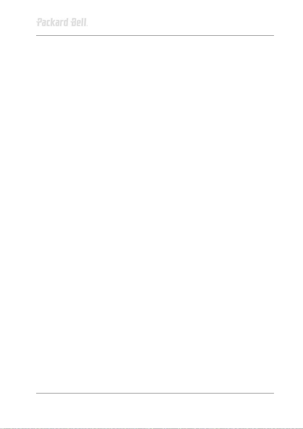
Removing the Battery
Perform the following steps to remove the battery:
1. Make sure to power off the EasyNote S.
2. Disconnect the AC adapter (and all other peripherals) from the unit.
3. Turn the unit upside down.
4. Unlock the battery compartment and slide it out of its place.
4
Fig. 1 Releasing the battery.
Removing the Hard Disk Drive
To remove the hard disk drive, then perform t he following steps:
1. Rem ove the 2 screws securing the hard disk drive cover on the front side.
2. Remove the 2 silver coloured screws underneath.
Fig. 2 Removing the 2 silver coloured screws.
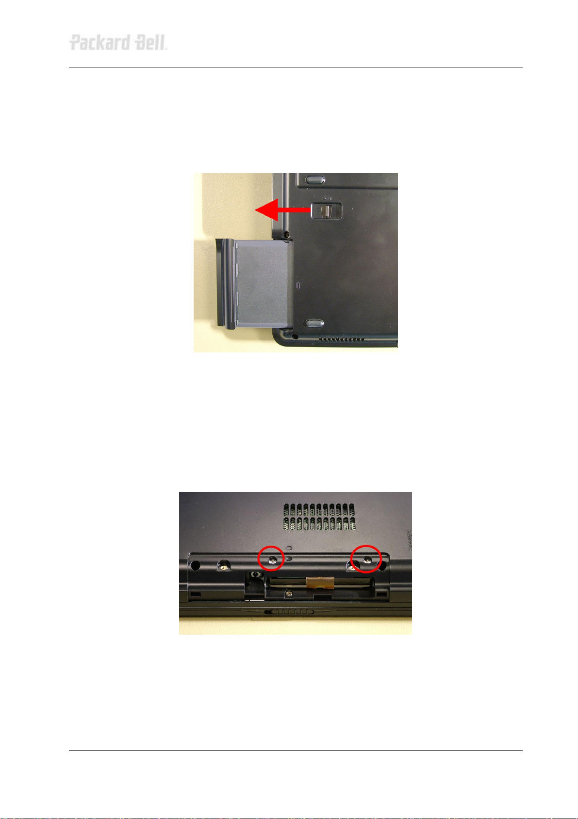
3. Pull out t he Mylar folded inside the drive bay.
4. Carefully slide the hard disk drive out.
Packard Bell EasyNote S Disassem bly Manual
Page 6
5
Fig. 3 Sliding out the hard disk dr ive.
Removing the Memory Module
There are two SO-DIMM slots, of which one is easily accessible (for end-users) and the ot her one
requires more disassembly.
SO-DIMM Slot 1
1. Remov e the screw securing the cover on the bottom of the casi ng.
Fig. 4 Removing the cover screw.
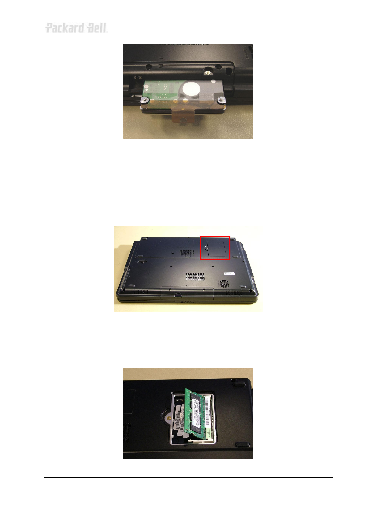
2. Remove the cover.
3. Push plastic clips aside.
4. Take out the SO-DIMM memory module.
Fig. 5 Taking out the memory module.
Packard Bell EasyNote S Disassem bly Manual
Page 7
6
SO-DIMM Slot 2
To remove the memory module in SO-DIMM slot 2, first remove the WLAN adapter (see Removing the
WLAN Mini-PCI Card), and then perform the following steps:
1. Remov ing the 3 screws securing the m etal plate located beneath the mi ni-PCI.
2. Lif t out the metal plate; The second SO-DIMM slot will now be visi ble.
3. Push the 2 cli ps aside and take out the SO-DIMM memory module.
Note There is only one end-user accessible SO-DIMM slot! If the unit shipped with two SO-DIMM
slots, they will usually be identical (if total memory size is 512, 1024 or 2048 MB). This will enable Dual
Channel memory architecture, allowing far greater memory speeds. Under these circumstances, it is not
recommended to upgrade just one of the memory module s.
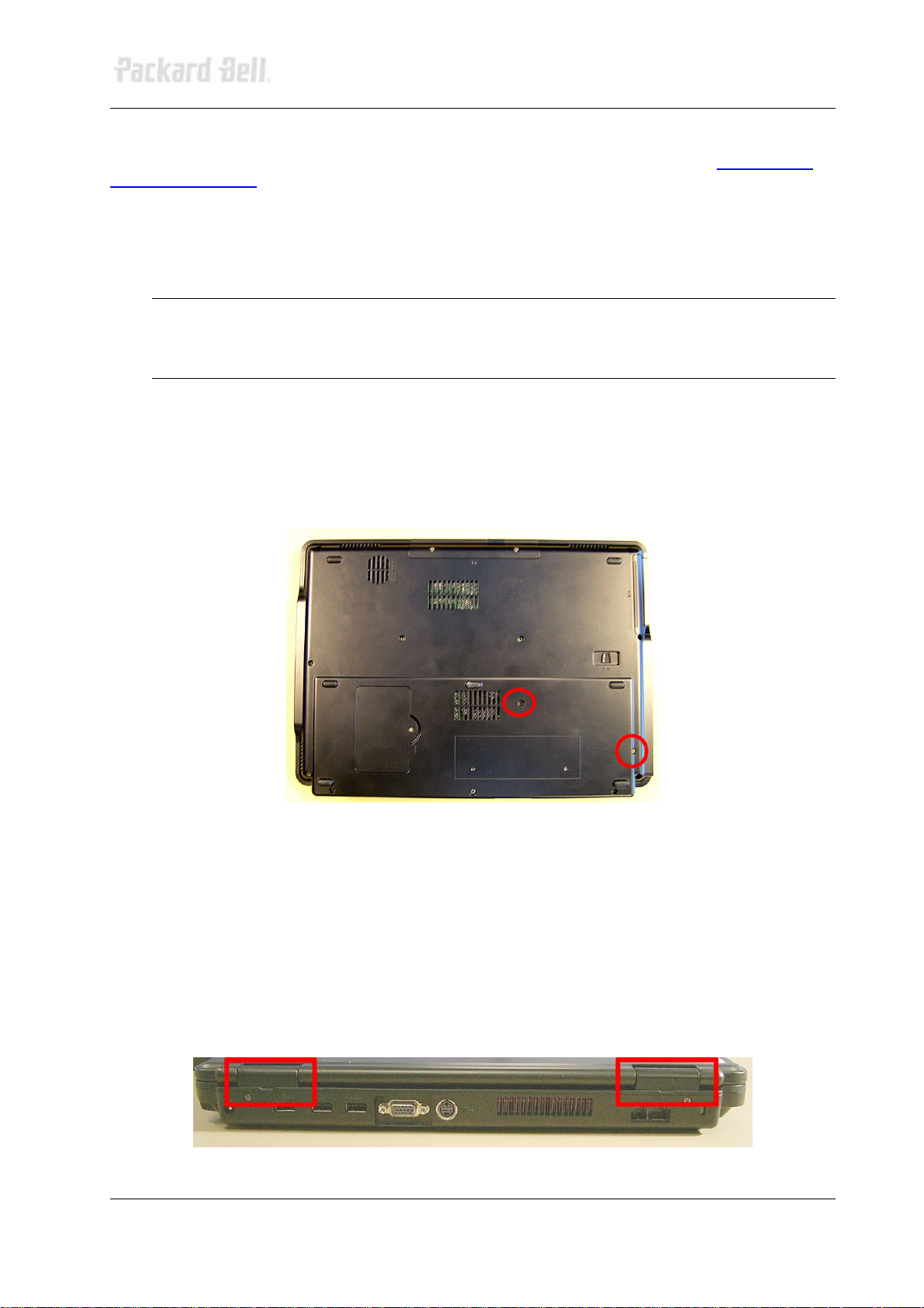
Removing the Optical Disk Drive
To remove the optical disk drive, perform the following steps:
1. Remove the indicat ed 2 screws on the bottom of the unit.
Fig. 6 Removing optical disk drive cover screws.
2. Pull out the optical disk drive (this is easier when you open the tray using the emergency eject
hole).
Removing the Button Panel
To remove the button panel (hinge and keyboard cover), perform the following steps:
1. Use a smal l flat-bladed screwdriver to lift the hinge/keyboard cover gently; There are 2
indicated gaps.
Fig. 7 Lifting the hinge/keyboard covers.
Packard Bell EasyNote S Disassem bly Manual
Page 8

7
2. Fold the LCD completely backwards.
3. Push up the hinge/keyboard cover, which is also the keyboard cover. Use moderate force
and/or use a screwdriver to lift the part on one side.
4. Fol d back the hinge/keyboard cover and disconnect the flat cable by pulling up the brown cli p
to release the flat cable.
Fig. 8 Button panel flat cable connection.
5. Remove the di sconnected button panel.
Removing the Keyboard
To remove the keyboard, first remove the button panel (see Removing the Button Panel), then perform
the following steps:
1. Pull the keyboard up f rom the top side and gently l ift the keyboard away.
2. Di sconnect the flat cable from the main board (pull up the white holder to release the flat
cable).
3. Take out the keyboard.
Note If you only need to replace the keyboard, you do not need to disconnect the flat cable of the
button panel.
Removing the Heat Shield
To remove the heat shield, first remove the button panel (see Removing the Button Panel
the keyboard (see Removing the Keyboard
1. Remove the 8 screws retai ning the heat shield.
), then perform the following steps:
) and remove
Packard Bell EasyNote S Disassem bly Manual
Page 9

8
Fig. 9 Screws marked A on the picture are marked 5 on the metal;
screw marked B on the picture is marked 15 on the metal.
2. Lift out the heat shield; it should look li ke this:
Fig. 10 A = WLAN mini-PCI card and 2nd SO-DIMM slot; B = CPU;
C = keyboard connector; D = glide pad connector; E = CPU fan.
Removing the WLAN Mini-PCI Card
To remove the WLAN mini-PCI card, first remove the heat shield (see Removing the Heat Shield
perform the following steps:
1. Disconnect t he 2 ant enna connectors (MAIN and AUX)
Packard Bell EasyNote S Disassem bly Manual
), then
Page 10

9
Fig. 11 The 2 antenna connectors: MAIN and AUX.
2. Push aside the cli ps f or the mini-PCI card.
3. Take out the mini-PCI card.
Removing the CPU
To remove the CPU, fi rst remove the heat shield (see Remov ing the Heat Shield
following steps:
1. Remove the CPU-fan (marked E in Fi g. 10) by removing the 2 screws and disconnecting the
power cable from the main board.
), then perform the
Fig. 12 CPU heat sink & VGA heat sink.
2. Rem ove the CPU heat sink: Loosen the 3 screws i n indicated order as marked on the heat
sink (1, 2, 3 on Fig. 13).
Packard Bell EasyNote S Disassem bly Manual
Page 11

10
Fig. 13 CPU heat sink.
), remove the button
), remove the
3. Lift out the CPU heat sink.
4. Turn the screw on t op of the CPU socket halfway (marked A in Fig. 13) with a flat-bladed
screwdriver; You should feel a click when the CPU is released.
5. Lift out the CPU from the socket.
Removing the VGA Heat Sink
To remove the VGA heat si nk, first remove the heat shield (see Removing the Heat Shield
CPU fan (see step 1 i n Removing the CPU), then perf orm the following steps:
1. Remov e the screw of the copper VGA heat sink (see Fig. 12).
Note The presence of the VGA heat sink is optional.
), remove the
Removing the Main Board
To remove the main board, first remove the battery (see Removing the Battery
drive (see Removing the Hard Disk Drive), remove the available memory modules (see Removing the
Memory Module), remove the optical disk drive (see Removing the Optical Disk Drive
panel (see Removing the Button Panel), remove the keyboard (see Removing the Keyboard
heat shield (see Removing the Heat Shield), remove the WLAN card (see Removing the WLAN Mini-PCI
Card), remove the CPU (seeRemoving the CPU), remove the VGA heat sink (see Removing the VGA
Heat Sink), rem ov e the LCD screen (see Removing the LCD Assembly), then perform the following steps:
), remove the hard disk
1. Rem ove the flat cable, next to t he LCD cable. You might have removed the flat cable together
with the button panel.
2. Remove the 2 hex-bolts adjacent to the VGA port.
3. Remove the 4 screws indicat ed on Fig. 14.
Packard Bell EasyNote S Disassem bly Manual
Page 12

11
Fig. 14 Removing the 4 screws in the top.
4. Fli p over the base unit and rem ove the 11 screws from the bottom of the base.
Fig. 15 10 Large screws (A) and 1 short screw (B).
5. Disconnect the flat cable of the glide pad and disconne ct the microphone cable.
Fig. 16 Glide pad flat cable and the microphone cable.
Packard Bell EasyNote S Disassem bly Manual
Page 13

12
6. Gently lift off the top cover.
Remove the 2 hex bolts on the main board; Next to the holes of t he hex bolts you should see a
7. Di sconnect all cables from the m ain board: LCD switch cable (at t he top near the LCD cable),
modem cable and speaker and subwoof er cables.
8. Remove the modem (see Removing the Modem).
9. Rem ove the 2 l ong screws and 2 short screws of the metal hard disk drive bay.
10. Push the DC jack out of it holder (right top side). You do not need to disconnect t he DC jack
from the main board!
11. Remov e the subwoofer (see Removing the Subwoofer
12.
symbol like an elli pse wit h a square across.
Fig. 17 Symbol on main board indicating hex bolts.
).
13. Remove the 4 screws on the main board; There is an encircl ed + symbol near their holes.
14. Sli de out the main board.
Note You have to pull the backside forward quite extensively to release the VGA port.
Note You can pull the left side of the casing outwards to allow more space for the PCMCIA eject
button and the audio connector to come out. The presence of PCMCIA is optional.
Removing the Modem
To remove the modem, first remove the main board (see up to step 6 in Removing the Main Board) t hen
perform the following steps:
1. Remove t he screw securi ng the modem.
Fig. 18 Removing the modem screw.
Packard Bell EasyNote S Disassem bly Manual
Page 14

13
2. Disconnect the modem cable from the m ain board.
3. Lif t out the modem.
Removing the LCD Switch
The LCD switch has been mounted on the backside of the casing; It is a small switch sticki ng out of the
top cover. To remove the LCD switch, first remove the main board (see up to step 6 in Removing the
Main Board), then perform the following steps:
1. Disconnect the cable from the main board.
Fig. 19 LCD switch cable connector.
2. Remov e the screw from the LCD switch and remove t he LCD swit ch.
Fig. 20 Removing the LCD switch screw.
Removing the Subwoofer
To remove the subwoofer, first remove the main board (see up to step 6 in Removing the Main Board),
then perform the following steps:
1. Disconnect the subwoofer cable from t he mai n board.
Packard Bell EasyNote S Disassem bly Manual
Page 15

14
Fig. 21 Speaker and subw oofer cable connection on the main board.
) then
2. Rem ove the 2 screws securing the subwoofer. Note that the screw holes in the subwoofer are
made of rubber, so the subwoofer feels very loose.
3. Take out the subwoofer.
Note The presence of a subwoofer is optional.
Removing the Speakers
To remove the speakers, first remove the main board (see up to step 6 in Removing the Main Board
perform the following steps:
1. Rem ove the 2 screws of the left speaker and the 2 screws of the right speaker.
Fig. 22 Removing the left and right speaker screws.
2. Rem ove the speaker cable from the metal clips (in base). To do so, bend the m et al.
Packard Bell EasyNote S Disassem bly Manual
Page 16

15
Fig. 23 Metal clip securing the speaker cable.
3. Take out the speakers.
Note The two speakers are one part, so they cannot be exchanged separately.
Removing the Glide Pad
To remove the glide pad, first remove the main board (see up to step 6 in Removing the Main Board
then perform the following steps:
1. T he glide pad is mounted on the top cover and consists of two parts: The glide pad surface
and the buttons.
2. For the button panel: Remove the 2 screws and disconnect the flat cable from the glide pad.
),
Fig. 24 Removing the glide pad screws and flat cable.
3. Lift the button panel and slide it backwards.
4. Lift the panel away and disconnect the flat cables.
5. For the glide pad surface: Remove the flat cable coming from the button panel.
6. Push out the glide pad, which has been glued to the top cov er.
Removing the Microphone
Packard Bell EasyNote S Disassem bly Manual
Page 17

16
To remove the microphone, first remove the main board (see up to step 6 in Removing the Main Board),
then perform the following steps:
1. Push out the microphone from the top cover using a small flat-bladed screwdriver or tweezers.
2. Caref ully bend the metal clips open to remove the cable from the top cov er.
Fig. 25 Metal clips securing the top cover cable.
3. Remove the microphone.
Removing the LCD Assembly
To remove the LCD assembly, first remove the heat shield (see Removing the Heat Shield
the following steps:
1. Disconnect the LCD cable from the main board.
Fig. 26 LCD cable connection on the main board.
2. Remove the 2 screws on the back of the system.
3. Rem ove the 2 screws in the bottom base, directly under the screws you rem oved on the back.
4. Carefully lift out the entire LCD panel.
), then perform
Removing the LCD Panel
To remove the LCD panel, first remove the LCD assembly (see Removing the LCD Assembly), then
Packard Bell EasyNote S Disassem bly Manual
Page 18

17
perform the following steps:
1. Push out the 6 rubber stoppers (4 at the top and 2 at the bot tom).
Fig. 27 Location of rubber stoppers on the LCD assembly.
2. Remove the 6 screws underneat h the stoppers.
3. Remove the LCD bezel. The bezel has been clicked into place and you need to pull hard to
loosen it.
4. Disconnect the cables from the inverter board.
Fig. 28 Power cable connected to the inverter board.
Packard Bell EasyNote S Disassem bly Manual
Page 19

18
Fig. 29 Data cable connected to the inverter board.
5. Rem ove the 2 screws in the met al brackets in the l ower left and right corner.
Fig. 30 Screws location in the metal bracket.
6. Lift out the LCD panel.
7. Remove the metal brackets on each side (4 screws per side).
8. LCD data cable: Press the metal holder on each side and pull the cable loose from the
connector on the LCD panel.
Fig. 31 Disconnecting the LCD data cable.
Removing the Inverter Board
To remove the inverter board, first remove the LCD panel (see up to step 4 in Removing the LCD Panel),
then perform the following steps:
1. Remove the screw securing the inv erter board.
Packard Bell EasyNote S Disassem bly Manual
Page 20

19
Fig. 32 Location of screw securing the inverter board.
2. Remove the inverter board.
Removing the WiFi Antenna
The WiFi antenna is woven into the metal shielding in the LCD top cover. To remove the WiFi antenna,
first remov e the LCD panel (see up to step 6 in Removing the LCD Panel
steps:
1. Rem ove the metal brackets on the top on each side of the LCD back cover.
), then perform the following
Fig. 33 Metal brackets on LCD back cover.
2. Release the WiFi antenna and remove it from the back cover.
Reassembly Notes
To clip the keyboard in place, you have to insert the keyboard/hinges cover into the metal clips mounted
on the heat shield. Insert the hinge-side last.
Packard Bell EasyNote S Disassem bly Manual
Page 21

20
Notice
The information in this guide is subject t o change without notice.
This guide contains information protected by copyright. No part of this guide may be photocopied or
reproduced in any form or by any means without prior written consent from NEC Computers International
B.V.
NEC COMPUTERS INTERNATIONAL B.V. SHALL NOT BE LIABLE FOR TECHNICAL OR EDITORIAL
ERRORS OR OMISSIONS CONTAINED HEREIN; NOR FOR INCIDENTAL OR CONSEQUENTIAL
DAMAGES RESULTING FROM THE FURNISHING, PERFORMANCE, OR USE OF THIS MATERIAL.
Copyright © 2005 NEC Comput ers International B.V. All rights reserved.
Packard Bell is a trademark of NEC Computers Inter national B.V.
The names of actual companies and products mentioned herein may be trademarks and/or registered
trademark s of their r espect ive owners.
The software described in this guide is furnished under a license agreement or nondisclosure agreem ent.
The software may be used or copied only in accordance with the terms of the agreement.
EasyNote S Disassembly Manual
Author: Juan M. Calviño & Wouter Willemse - Product Support Consumer
First Edition: October 2005
Document Part Number: 6980650000
Version: 1.0
Packard Bell
A division of NEC Computers International B.V.
Packard Bell EasyNote S Disassem bly Manual
 Loading...