

Page 1
Disassembly Manual
Page 2

Tabl e of contents
Overview ................................... ............... ............................. .............. ............... .............. .............. ............... .............. ............3
Tech nician Not es.................................................................................................................................. ............................ .....3
Disassembly Instructions........ ............................. ............... ............................ ............... .................................................. .....3
Reassembly Instructions ..................................... ............................. .............. ............... .................................................. .....3
Requ ired Tools.................. ....... ............... ....... ............... ....... ....... .............. ........ .............. .............. ............... ..........................3
Hazard ous Voltage...................................................................................................................................... ..........................4
Avoid Electrostatic Discharge............... ............... ............................ .............. ............... .............. ............... ..........................4
Power Supply Unit................................................................................................................. .............. ............................. .....4
Removing the Battery............................. ............... ............................ .............. ..................... ........ ............... .............. ............5
Remov i ng the Memory M odule......................................................................................................................... .............. .....6
Removing the Hard Disk Drive...... ............................. .............. .............. ............................. ................................................7
Removing the CPU........................................ .............. ............................. ............... .................................................. ............8
Removing the Keyboa rd..................................................... .............. .............. ................................................... .............. .....9
Removing the Optical Disk Drive .............................. ............... .............. ............................. .................................... ..........10
Removing the LCD Module.......................... .............. ............................. ............... .................... ........ ............... .................11
Removing the LCD Panel....... ............... ............................. .............. ............... .................................................. .............. ...13
Removing the Bottom Cover........................ ............... ............................ ............... .................... ......... .............. .................16
Removing the MDC Modem....................................... ............................. ............... .............. ............................. .... .......... ...17
Removing the Chipset Heat Sink...................................... .............. ............................. .............. .. ........................... ..........18
Removing the Main Board....... .............. ............................. .............. ............... .................................................. .............. ...19
Removing the Tou ch Pad...................... ............................. .............. ............... .................................................. .............. ...21
Removing the Speaker Assembly..................................... ............................. .............. .................. ........... .............. ..........22
Screws.................. .............. ............................. ............... ............................ ............... .. ........................... .............. .................23
Notice............. .............. ............... .............. ............................. .............. .................................................. ............... .............. ...24
Pack ard Bell EasyNote F5/F7 Disassembly Manual
Page 2
Page 3

Overview
Thi s document conta ins st ep-by-steps disassembly instructi on s for the EasyNot e F5/F7 cha ssis . The in stru ctions
ar e illustrated wh er e n ecessary with images of the part that i s being r em oved or disassem bled. Furthermore, the
screws that are removed are shown next to the image of the parts themselves.
NEC re s erves th e right to make chang e s t o th e Eas y Note F 5 /F 7 chassis wi thout n o tice.
Technician Notes
Only technicians authorized by NEC Computers Int ernational BV should attempt to repa ir this equipment. All
troubleshooting and re pair procedures ar e deta iled to allow only subassembly/module level repair. B ecause of the
complexity of the indi vidual boards and subassemblies, no one should attempt to make repairs at the component
lev el o r to make modifications to any print ed wiring boar d. Im proper repairs can create a safety haza r d. Any
in di cation of comp onen t replacement or print ed wir ing board modifications may voi d any wa rranty or exchange
allowances.
Disassembly Ins tructions
When disassem bling th e system unit, f ol l ow these general rules :
Do not disassemb l e the s y s tem i nto pa rts th at are sm aller than thos e specifie d in the instr u ct ions .
Label all remove d connectors. Note where the connector goes and in what position it was install ed.
Turn off th e pow er an d d i sconnect all pow er and all options.
Reassembly Instructions
Reassembly is the reverse of the disassembly pr ocess. Use ca re to ensu re tha t all cables and screws are returned
to their proper positions. Check that no tools or any loose parts have been left inside the chassis. Check that
everything are properly inst alled and tightened.
Required Tools
Al l di sassembly procedures can be perform using the following tools:
PH 0x 6 0 Ph il i p s screw driv er
PH 0x 4 0 Ph il i p s screw driv er
4.0 x 60 Flat screwdriv er
2.0 x 30 Flat screwdriv er
SW5.0 Spacer screwdriver
Small tw eezers
Pin
Pack ard Bell EasyNote F5/F7 Disassembly Manual
Page 3
Page 4

Hazardous Voltage
There is hazardous voltage present inside the computer
when it is connect to an AC su pply, ev en w hen the
computer’s power switch is off. Exposure to hazardous
vol ta ge could caus e per sonal injury. To avoid risk of injury,
conta ct an Authori zed Service Provider for proper
(un) in sta llation of optional hardware devi ces.
Av oi d Ele c tr os tati c Dis c har ge
Electro sta ti c el ectr i city can easi ly damage circuit cards and
in tegrated circu its (ICs). To r educe risk of damage, stor e
them in protective packaging whenever they are not
installed in y our system.
Add-in cards can be ext remely sensitive to ESD and always
re quir e careful handling. After removing the card from the
com put er, plac e the car d flat on a gr ounded, static-free
surface, component-side up. Use a condu ctive foam pad if
avai lable, but not the car d wrapper . Do not slide the ca rd
over any surf ace.
Before you i nstall or remove memory mod ules, vi deo
m emo ry, disk drives, c ircui t cards or other devices, protect
th em from stati c electr icity. To do so, make sur e your
com put er’s power switch is OFF. Then, unplu g the
com puter’s AC power cord. Be fore pick ing up the devic e you
(un)install, you should wear an anti-static wrist wrap
(available at electr onic sup ply stor es). Be sure t o conn ect
the wrist wr ap to an unpainted metal portion of the computer
chassis. As an al ternative, you can dissipate electros t atic
bui l d-up by touching an unpain t ed metal port i on of th e
com put er chas sis with one hand. Th en tou ch the device you
are (un)installing wi th the other hand, and maintain
continuous contact with it until it is (un)installed in the
computer.
Pow e r Su p ply Un it
Under no circumstances should you attempt to disassemble
th e power supply. The power supply contains n o userserv iceabl e part s. In side the power supply are hazardous
voltages that can cause seriou s personal injury. Always
return a def ective power supply to your dealer.
WARNING
Ensure that the computer is disconnected from
its power sour ce and from all
telecommunication s links, networks, or modem
lines wh enever the chassis cover i s rem oved.
Do not operate t he comp uter with the cover
removed.
AVERTISSEMENT
Assurez-vous que le système est débranché de
son alime ntation ainsi que de to utes les
liaisons de télécommunication, des réseaux , et
des lignes de modem a vant d’enlever le capot.
Ne pa s utiliser le sy stème quand le cap ot est
enlevé.
WARNUNG
Das S ystem dar f weder an eine Stromquelle
angeschlossen sein noch eine Verb in dung m it
ein er Telekommunikation seinrichtung, einem
Netzwerk oder einer Modem-Leitung hab e n,
wenn die Gehäusea bdeckung entfe rnt w ir d.
Nehm en S i e das Sy st em n icht ohne die
Abdeckung in Betrieb.
ADVERTENCIA
Asegúrese de que cada vez que se quite la
cubierta de l chasis, el sistema haya sid o
desconectado de la red de alimentación y de
tod o s l o enlaces de telecomunicac iones, de red
y de líneas de módem. No ponga en
fun cionamiento el sistema mientras la cubierta
est é quitada.
WAARSCHUWING
Zorg er voor dat al l e verbind ingen va n en naar
de com puter (stroom, modem n etwerk, etc)
ver broken worden voor dat de behuiz ing
geopend word t. Zet de computer nooit aan al s
de behuiz i ng geopend i s.
AVVERTENZA
Prima di rimuovere il coperchio del telaio,
assicurar si che il sistema s ia scollegato
dall’alimen tazione, da tutti i c o llega menti di
comunicazione, ret i o linee di modem. Non
avvia re il siste ma senza aver prima messo a
post o il coperchio
Pack ard Bell EasyNote F5/F7 Disassembly Manual
Page 4
Page 5
Re m ovi ng the Bat t ery
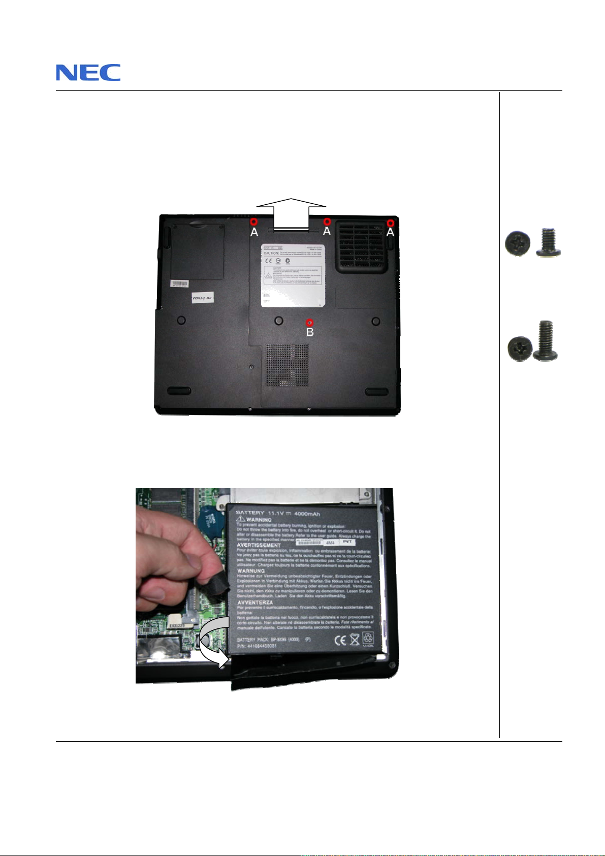
Perform the follo wing ste p s to remove the ba tter y:
1. Make sure to power off the EasyNote F5/F7.
2. Turn t he unit upside down.
3. Unscrews th e bott om cover do or and sl i de it ou t of it s pla ce as the arrow shows in Fig. 1
Fig. 1 Removing Bottom cover door
4. Pul l up the bat tery as shows in Fig. 2
Fig. 2 Pull up battery
Pack ard Bell EasyNote F5/F7 Disassembly Manual
A = M2.5x4.5
Black
B = M2.5x7 Black
Page 5
Page 6
Removing the Memory Module
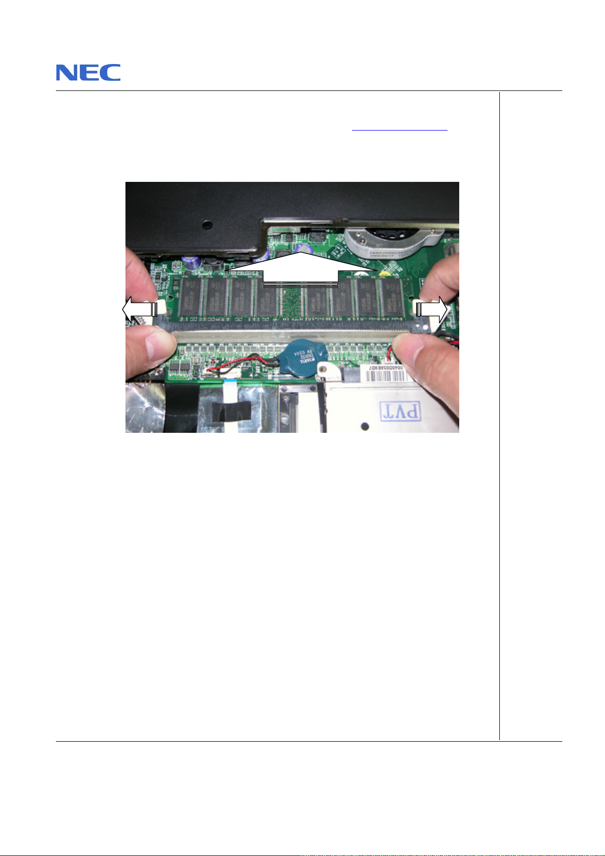
To remove th e M em ory Modul e, first rem ove the batt ery (see Removing the Battery), then
perform the follow in g ste ps:
1. Unclip the memory modul e as shown in Fig. 3
Fig. 3 Removing the memory module
2. Remo ve the memory module from its slot and put it aside.
Pack ard Bell EasyNote F5/F7 Disassembly Manual
Page 6
Page 7
Removing the Hard Disk Drive
1
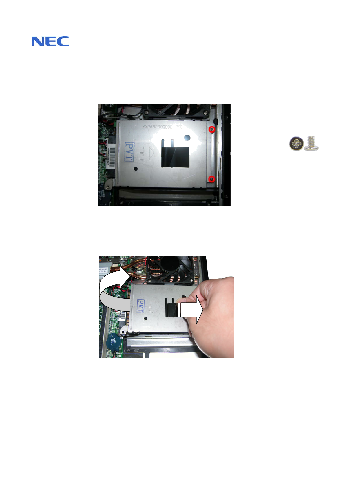
To remove the hard disk drive, first r emove the battery (see Remo vin g the Battery), then
perform the follow in g ste ps:
1. Remo ve the screws as shown in Fig. 4
Fig. 4 Screw retaining the HD D module
2. Caref ully pull the HDD module out from the base unit as shown in Fig. 5 .
2
Fig. 5 Removing HDD module
Pack ard Bell EasyNote F5/F7 Disassembly Manual
M2x3.5 Silver
Page 7
Page 8
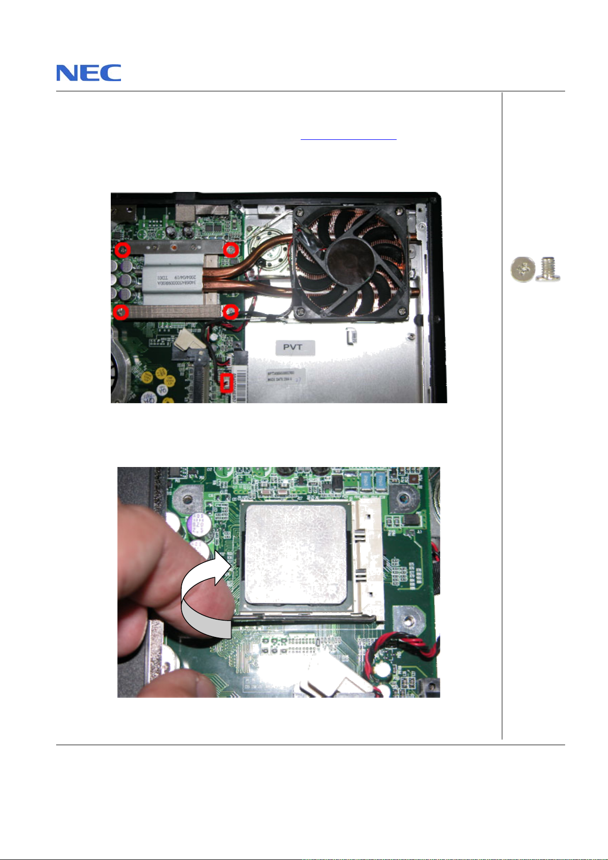
Removin g the CPU
To remove the CPU first remove th e battery (see Removing the Battery) then perform the
fol lowing steps:
1. Unscrew screws on CPU Heat Sink a s show n in Fig. 6
Fig. 6 CPU Heat Sink
2. U n lock the CPU from the CPU sock e t and lift up the C PU carefu lly.
Fig. 7 Unlocking t he CPU
Pack ard Bell EasyNote F5/F7 Disassembly Manual
M3x5 Silver
Page 8
Page 9
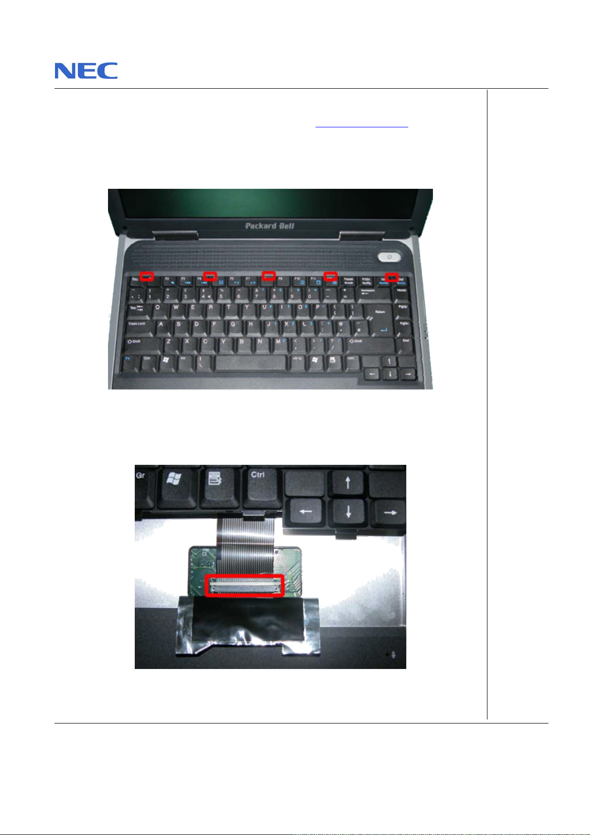
Removin g the Keyboar d
To remove the Key board, first remove the battery (see Removing the Battery), then per for m
the following steps:
1. Rel ease th e keyboard from the base uni t by push KB loc k with flat screws driver as shown
in Fig. 8
Fig. 8 Releasing the keyboard cover
2. Lift up th e keyboard and dis connect it from th e syst em a s shown in Fig. 9
Fig. 9 Disconnecting the keyboard flat cable
Pack ard Bell EasyNote F5/F7 Disassembly Manual
Page 9
Page 10
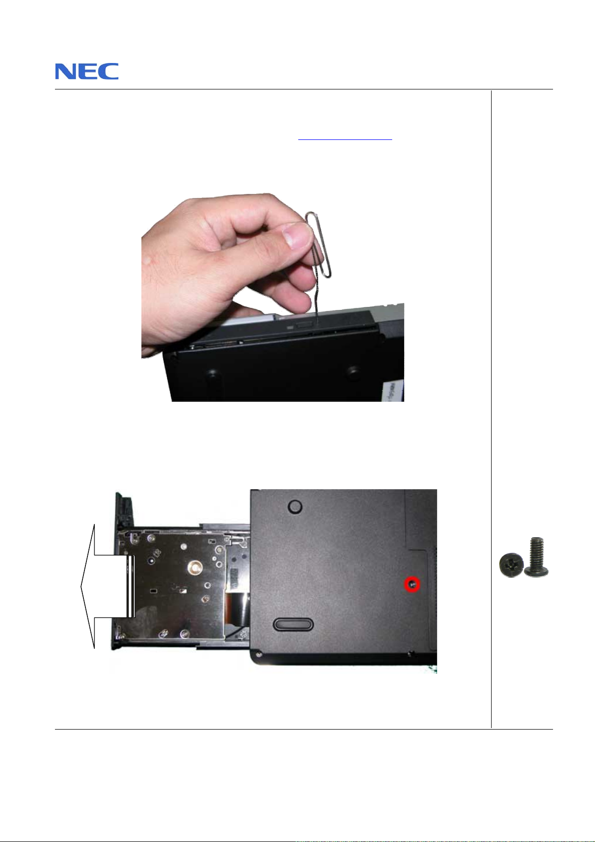
Removing the Optical Disk Drive
To remove the ODD, first rem ov e th e battery (see Rem ov i n g th e Battery) then perform the
fol lowing steps:
1. Use p in to eje ct ODD tr ay as shown in Fig. 10
Fig. 10 Ejecting ODD tray
2. Flip over the unit, unscrew and pull the ODD module out from the base unit as shown in
Fig . 11
M2.5x7 Black
Fig. 11 Pull the optical driv e out from the base unit
Pack ard Bell EasyNote F5/F7 Disassembly Manual
Page 10
Page 11
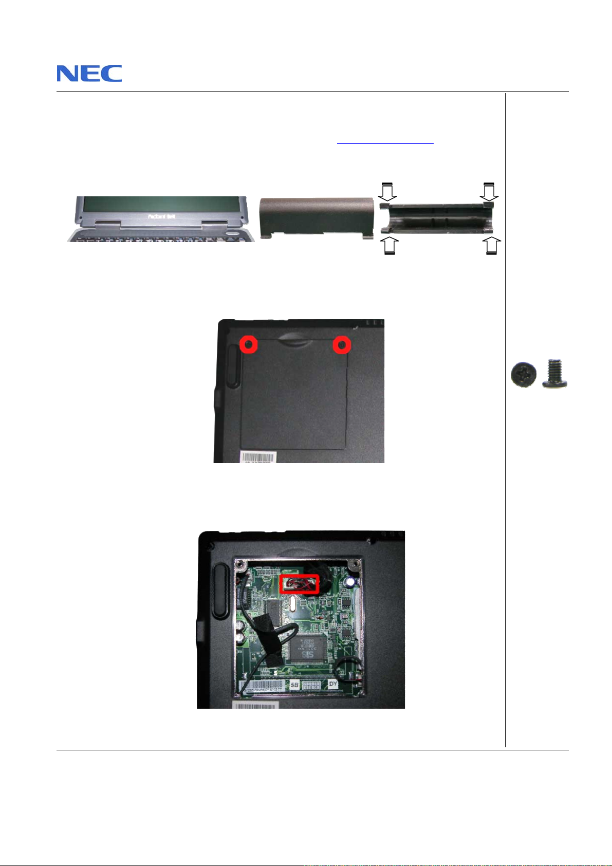
Removin g the LCD M odule
To remove th e LCD Module first remove the batt ery ( see Removing the Battery) the n pe rfo rm
the following steps:
1. To remove hing e cover, apply pressure at both en d of the hinge cover as shown in Fig. 1 2
Fig. 12 Removing the hinge cover
2. Flip over the unit and unscrew mini PCI slot cover as shown in Fig. 13
Fig. 13 Removing mini PCI slot cover
3. Flip over the unit and unscrew mini PCI slot cover as shown in Fig. 14
Fig. 14 Disconnecting LCD Cable
Pack ard Bell EasyNote F5/F7 Disassembly Manual
M2.5x4.5 Bl ack
Page 11
Page 12
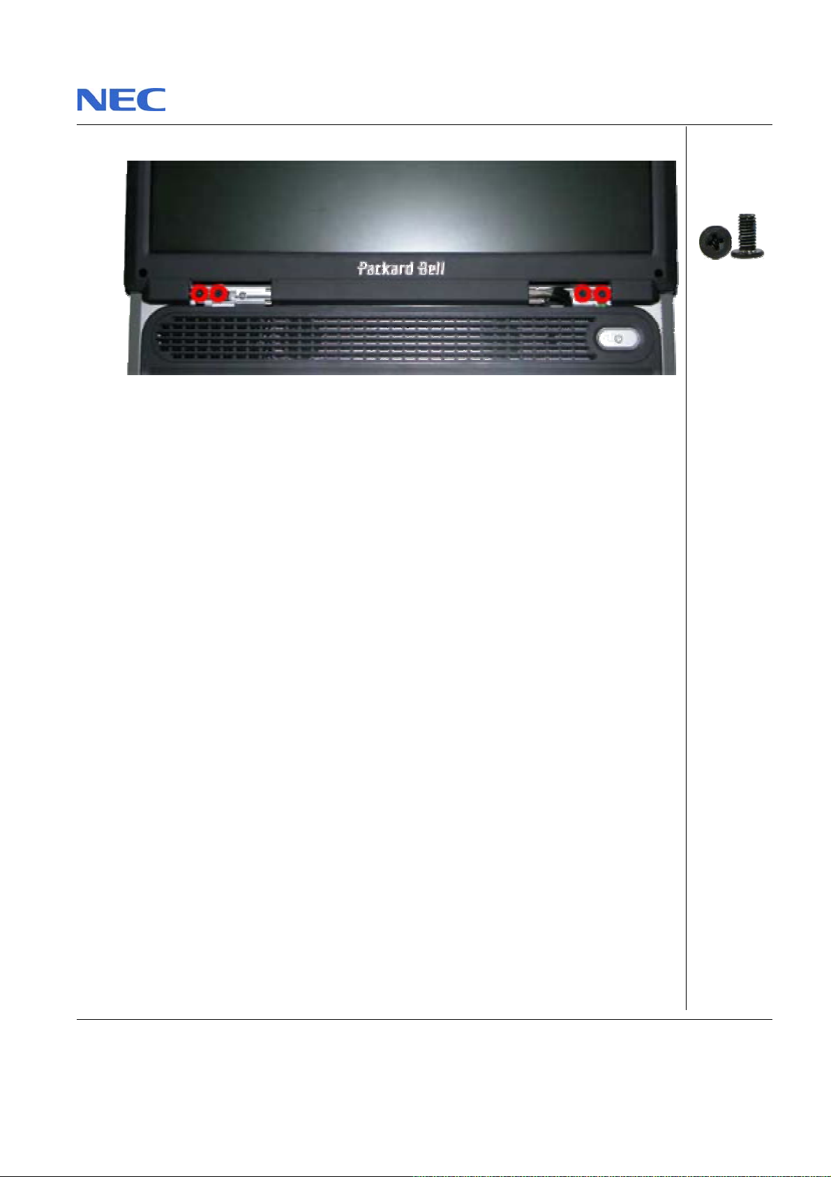
4. Release two scr ews at both side of LCD hin ge, r ema in tw o outer screws attached.
Fig. 15 Removing screws at LCD hinge
5. Carefully separate the LCD Module fr om the bas e unit.
Pack ard Bell EasyNote F5/F7 Disassembly Manual
M3x7 Black
Page 12
Page 13
Removin g the LCD P anel
To remove th e LCD panel, first rem ove the LCD module (see Remov ing the LCD Module),
then perform the following steps:
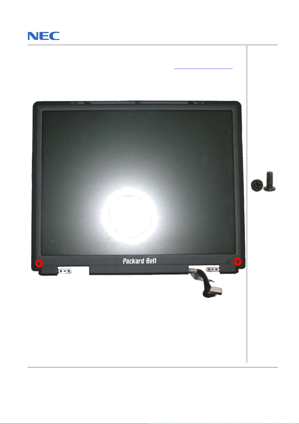
1. Use a pin to remove th e rubber cover on the LC D m odule as shown in Fig. 16
2. Remove all screws as shown in Fig. 16
M2.5x7 Black
Fig. 16 Removing the rubber covers & screws on the LCD Module
Pack ard Bell EasyNote F5/F7 Disassembly Manual
Page 13
Page 14
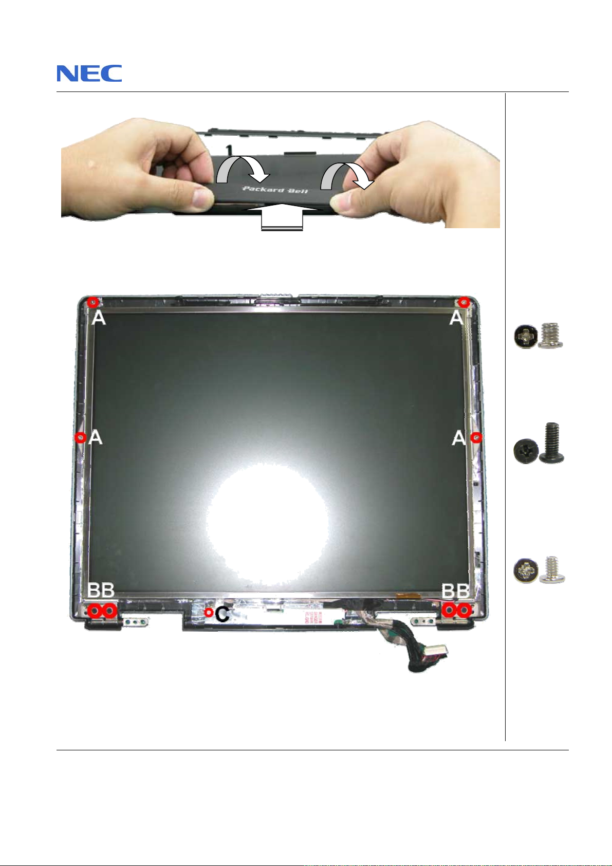
3. Car efull y re lease LCD B eze l fo rm LCD m odule as shown in Fi g. 1 7
Fig. 17 Removing the LCD Bezel
4. Release all screws in LCD module as shown in Fig. 18
A = M3x4 Silver
B = M2.5x7 Black
C = M2x3.5 Silve r
Fig. 18 Removing the screws at LCD Module
Pack ard Bell EasyNote F5/F7 Disassembly Manual
Page 14
Page 15
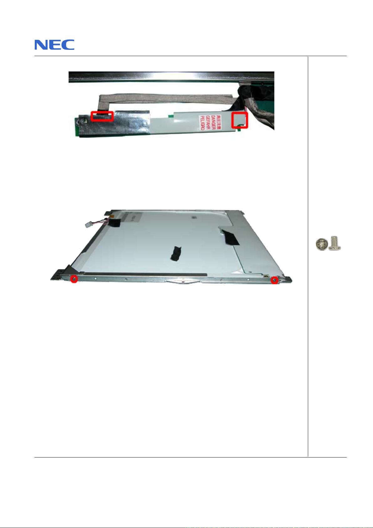
5. Disconnect all cable on Inverter Board.
Fig. 19 Inverter Board
6. Carefull y lift up th e LCD p ane l.
7. Remove th e scr ews at both si des of th e LCD panel in order to rel ease th e LCD hinges as
shown i n Fig. 20
M2x3.5 Silver
Fig. 20 Removing the LCD Panel hinges
Pack ard Bell EasyNote F5/F7 Disassembly Manual
Page 15
Page 16
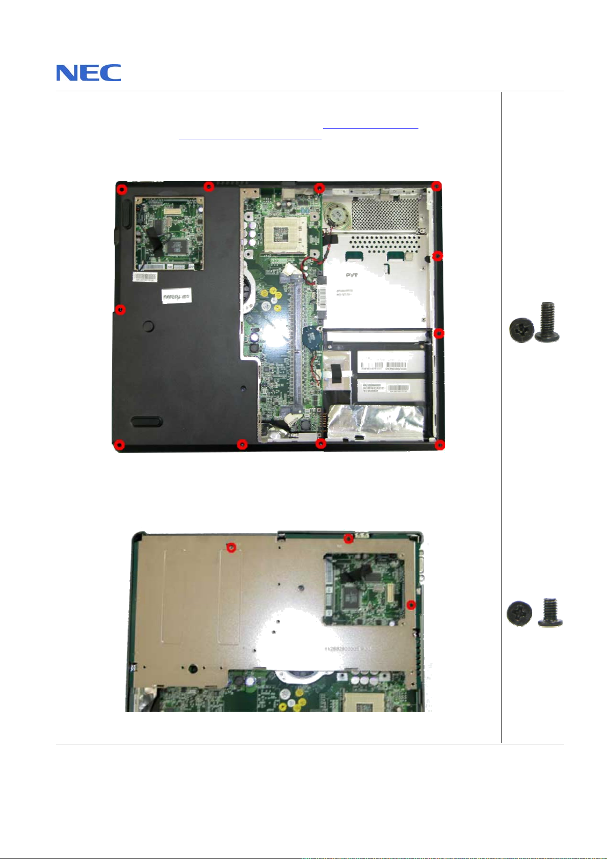
Removing the Bottom Cover
T o re move the T op Cover , first rem ove the ba ttery ( s e e Re mo ving the Battery), re mo ve t he
Optical Dis k Drive (see Removing the Optical Disk Drive
1. Rem ove all screws on th e bott om of the base unit as shown in Fig. 21
) then perfor m the followin g steps:
Fig. 21 Bottom Cover
2. C arefully lift up Bottom Co ver from base unit.
3. Remove all screw Bot tom Shield as s hown in Fig. 22 and place it aside.
Fig. 22 Bottom Shield
Pack ard Bell EasyNote F5/F7 Disassembly Manual
M2.5x7 Black
M2.5x4.5 Bl ack
Page 16
Page 17
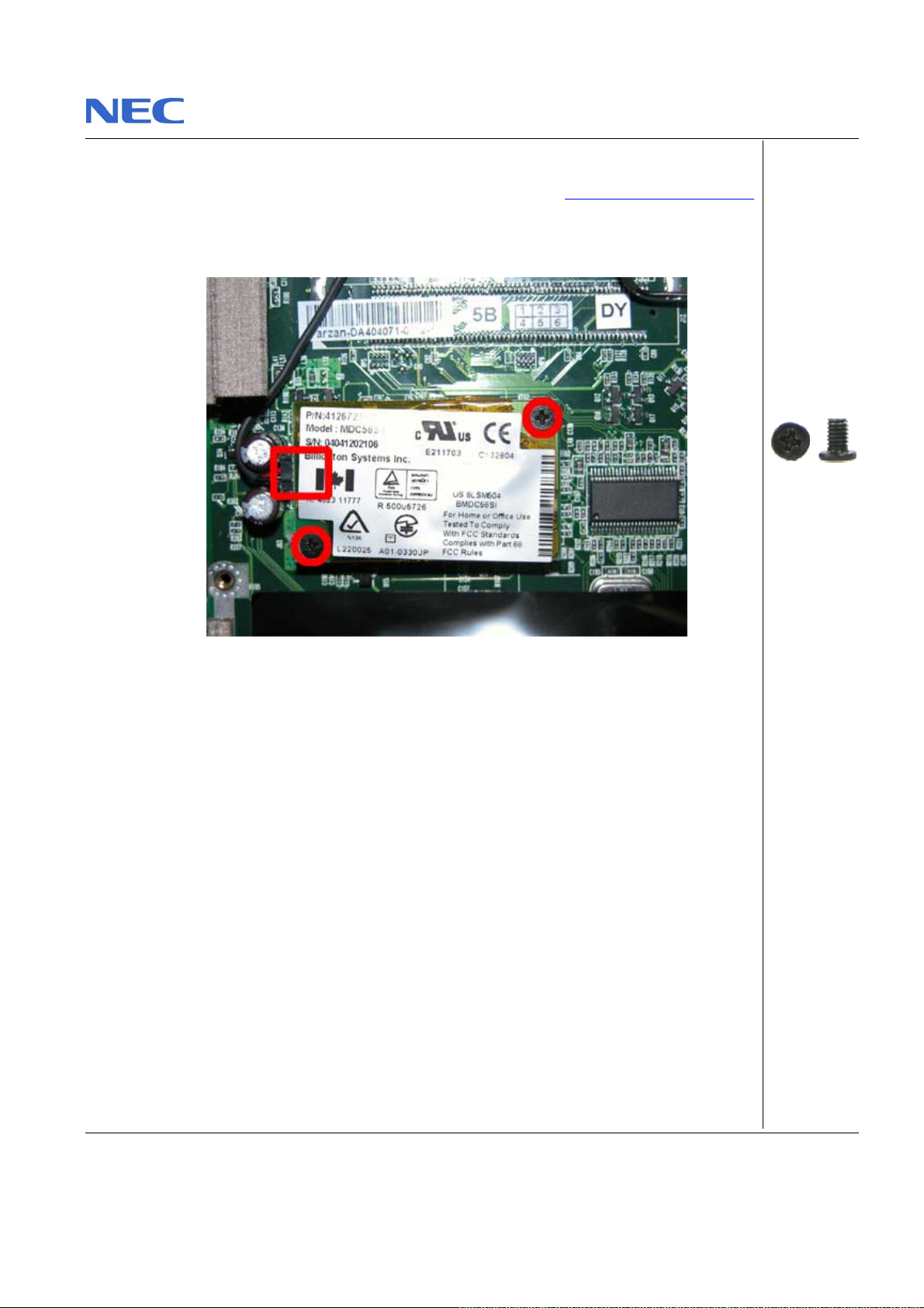
Removing the MDC Modem
To remove th e MDC M odem , first remove th e Bott om Cov er ( see Removing the Botto m Cover)
then perform the following steps:
1. Release screws and di sconnect cabl e on MCD M odem as shown in Fi g. 23
2. Lift up the MDC modem and put it aside.
Pack ard Bell EasyNote F5/F7 Disassembly Manual
Fig. 23 MDC Mode m
M2.5x4.5 Bl ack
Page 17
Page 18
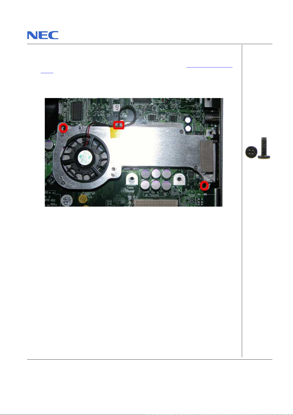
Removing the Chipset Heat Sink
To rem o ve the Chipset heat sink, first remove the Bottom c over (see Rem oving the Bottom
), then perform th e fol lowing steps:
Cover
1. Unscrew the screws on the Chipset Heat sink and disconnect the fan connector as shown
in Fig. 24
Fig. 24 Chipset Heat sink
2. Carefully lift up heat sink from Main Board.
Pack ard Bell EasyNote F5/F7 Disassembly Manual
M2x7 Black
Page 18
Page 19
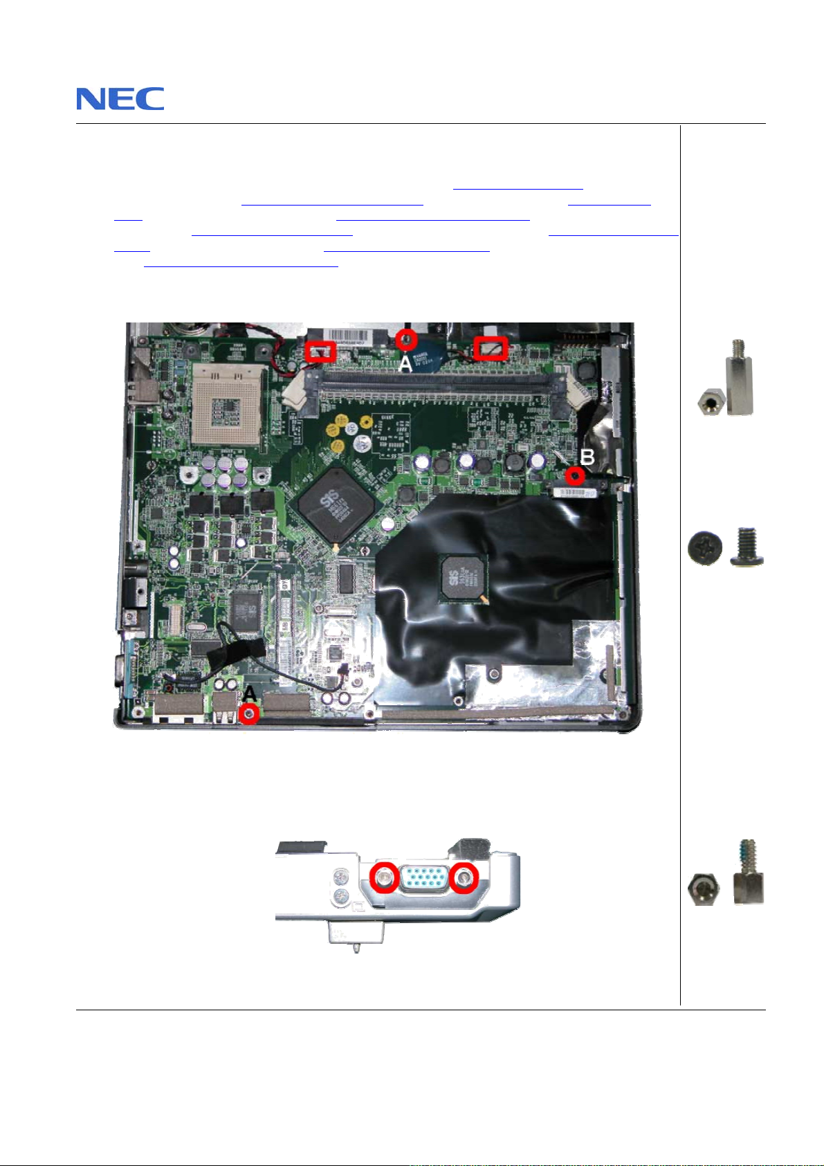
Removing the Main Board
To re mov e the M a in Boar d, fir st r em ove the Battery (se e Removing the Battery), remove the
Hard Disk Drive (see Re m ov ing th e Har d Disk Drive
CPU), remove the Optical Drive (see Removing the Optical Disk Drive), remove the LCD
Module (see Remov ing the LCD Module
), remov e the Bottom cover (see Removing the Bottom
Cover), remove MDC Modem (see Re m o vi ng th e M D C Mod em), remove Chipset Heat Sink
(see Remov ing the C hip set H eat Sin k
) then perform the following steps:
1. Remove the right hinge cover as shown in Fig. 25
), remove the CPU (see Removing the
Fig. 25 Removing the right hinge cover
2. Remov e the Hex screws from the VGA Port as shown in Fig. 26
A = M2.5x11.5
Silver
B = M2.5x4.5
Black
Fig. 26 VGA Port
Pack ard Bell EasyNote F5/F7 Disassembly Manual
M2.5x10 Silver
Page 19
Page 20
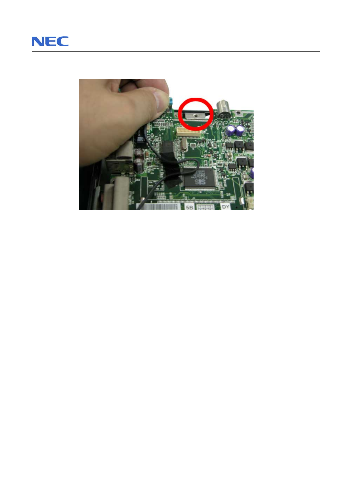
3. Pull the plastics par t near to audio port outward t o rel ease Main Boar d.
4. Be careful w hen lifting up the Main Boar d. The metal plate next to VGA port t ends to block
Ma in Board as show n in Fig . 27
Fig. 27 Lifting up Main Board
Pack ard Bell EasyNote F5/F7 Disassembly Manual
Page 20
Page 21
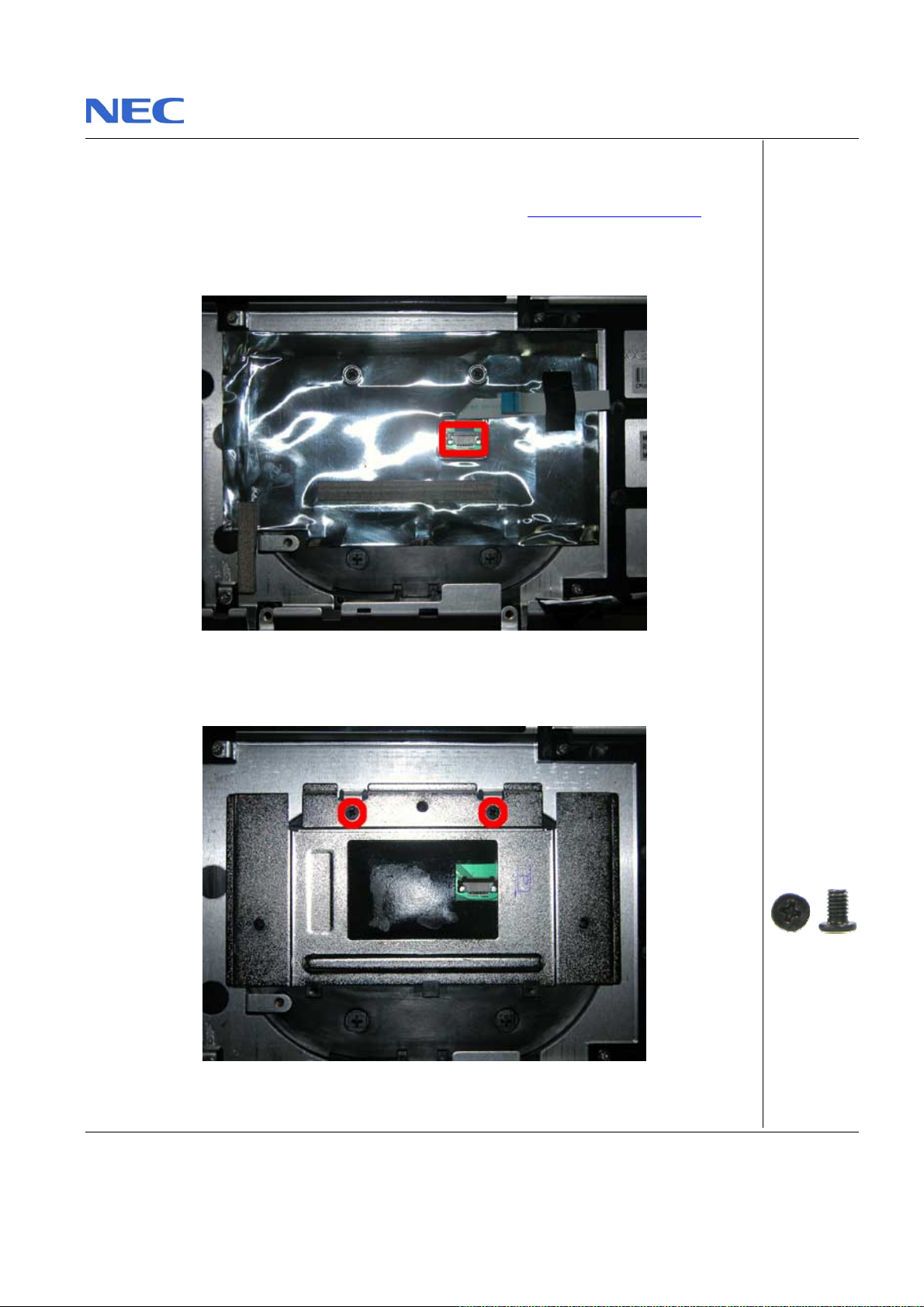
Remov i n g the Touch Pa d
To re move th e touch pad, first r emo ve the Main Board ( see Rem ovin g the Main Board ) then
perform the follow in g ste ps:
1. Disconnect the T ouch Pad and remove isola t or st i ck on it as shown in Fig. 28
Fig. 28 Touc h Pa d
2. Unscrew Touch Pad Holder to release Touch Pad as shown in Fig. 29
Fig. 29 Touch Pad Holder
Pack ard Bell EasyNote F5/F7 Disassembly Manual
M2.5x4.5 Bl ack
Page 21
Page 22
Removing the Speaker Assembly
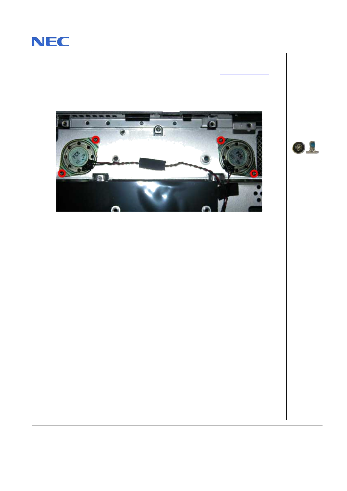
To remove the Speaker Assembly, first remove the Main Board ( see Removing the Main
Board) then perform the following steps:
1. Remove the screws holding Speaker Assembly as shown in Fig. 30
Fig. 30 Speaker Assembly
2. Carefully rem ove the Speaker a ssem bly from Top Cover and place it asid e.
M2x4 Silver
Pack ard Bell EasyNote F5/F7 Disassembly Manual
Page 22
Page 23
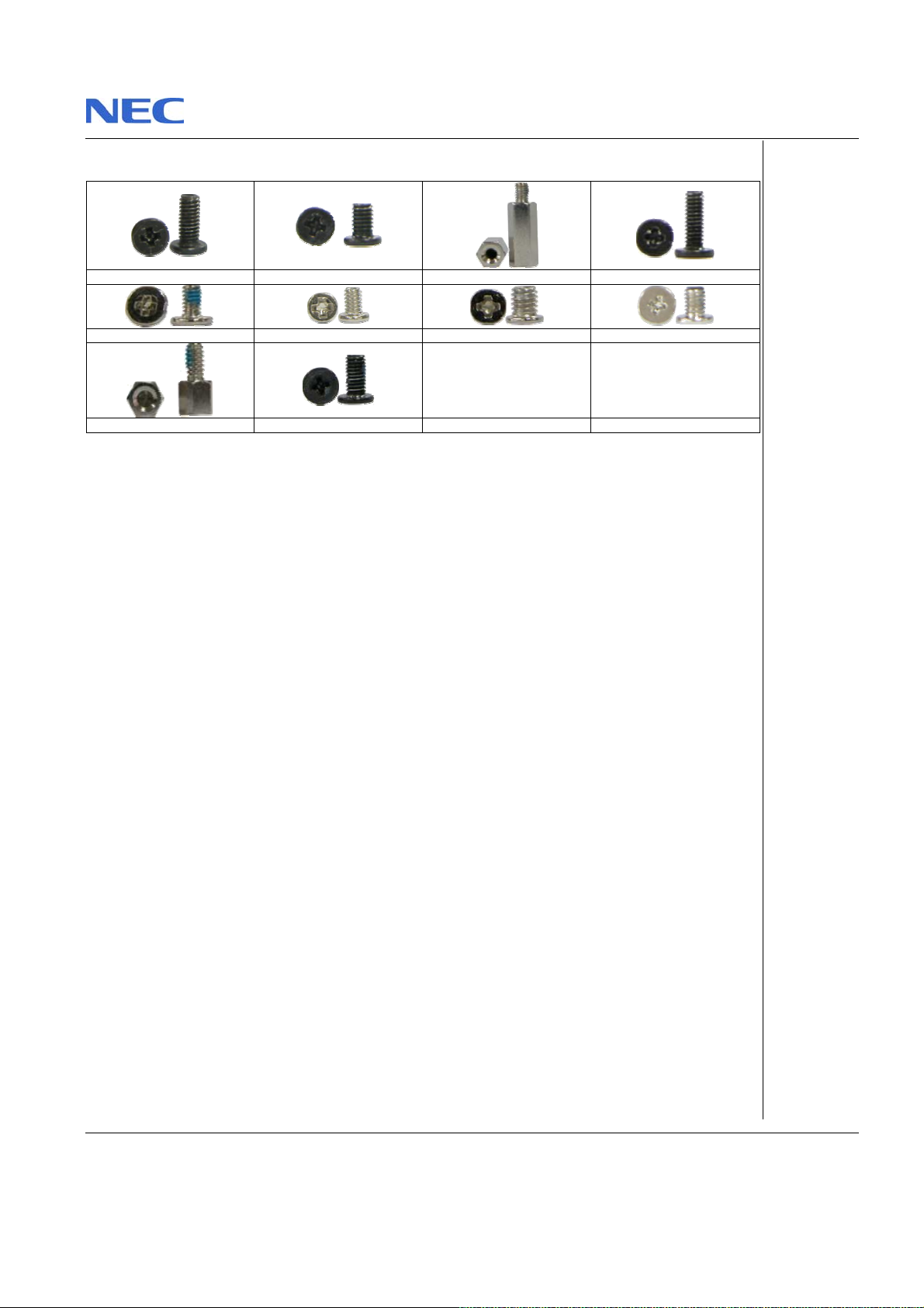
Screws
M2.5x7 Black M2.5x4.5 Bla ck M2.5x11.5 Sil ver M2x 7 Bl ack
M2x4 Silver M2x3.5 Silver M3x4 Silver M3x5 Silv er
M2.5 x10 Sil ve r M3x7 Bl ack
Pack ard Bell EasyNote F5/F7 Disassembly Manual
Page 23
Page 24

Notice
The information in this guid e is sub ject to change without not ice.
Thi s gui de contain s inform ation protect ed by copyright. No part of this gui de ma y be phot ocopie d or reproduced in
any fo rm or by any means without prior written consent from NEC Computers Intern at i onal BV.
NEC COMPUTERS INTERNATIONAL BV SHALL NOT BE LIABLE FOR TECHNICAL OR E DITORIAL ERRORS
OR OMISSIONS CONTAINED HEREIN; NOR FOR INCIDENTAL OR CONSEQUENTIAL DAMAGES RESULTING
FROM THE FURNISHING, PERFORMANCE, OR USE OF THIS MATERIAL.
Copyrig ht © 2004 NEC Computers Internatio nal BV. All rights reserved.
NEC is a trad em ark of N EC Com put ers In te rnational BV.
The names of actual companies and prod ucts mentioned herein may be trademarks and/or registered trademarks
of their respectiv e owners.
Packard Bell E asyNote F5/F7 Disassembly Manu al
Author: All en Koay
Fi rst E dit i on: Jun e 2004
Document Par t Num ber:
Version: 1.0
NECCM
A division of NEC Comput ers International B V
Pack ard Bell EasyNote F5/F7 Disassembly Manual
Page 24
 Loading...