

Page 1
Packard Bell
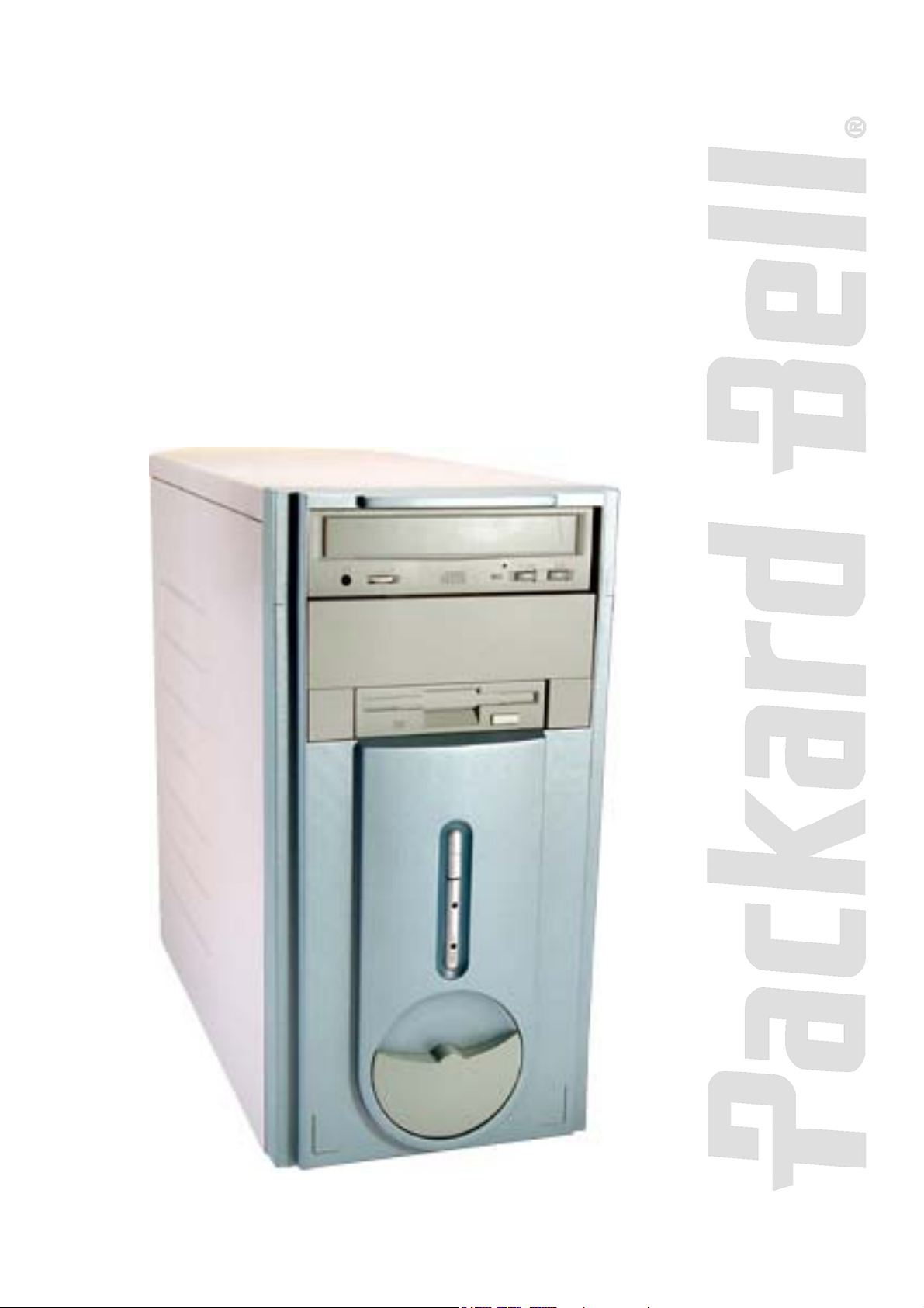
Cyclops (iMedia)
Disassembly Manual
Page 2

2
Table of Contents
Overview 3
Technician Notes 3
Disassembly Instructions 3
Reassembly Instructions 3
Required Tools 3
Hazardous Voltage! 4
Avoid Electrostatic Discharge! 4
Power Supply Unit! 4
Opening the Chassis 5
Removing the Front Bezel 6
Removing the DVD/CD-ROM Drive 6
Removing the Floppy Disk Drive 6
Removing the Hard Disk Drive 7
Removing Add-In Cards 9
Removing the Front USB Port 9
Removing the Switch/LED Assembly 9
Removing the Motherboard 10
Removing the Power Supply 10
Notice 12
Packard Bell Cyclops (iMedia) Disassembly Manual
Page 3

Overview
This document contains step-by-step disassembly instructions for the Cyclops (iMedia) chassis. The
instructions are illustrated where necessary with images of the part that is being removed or
disassembled. Furthermore, the screws that are removed are shown next to the image of the parts
themselves.
Packard Bell reserves the right to make changes to the Cyclops (iMedia) chassis without notice.
Technician Notes
Only technicians authorized by NEC Computers International BV should attempt to repair this equipment.
All troubleshooting and repair procedures are detailed to allow only subassembly/module level repair.
Because of the complexity of the individual boards and subassemblies, no one should attempt to make
repairs at the component level or to make modifications to any printed wiring board. Improper repairs can
create a safety hazard. Any indication of component replacement or printed wiring board modifications
may void any warranty or exchange allowances.
Disassembly Instructions
3
When disassembling the system unit, follow these general rules:
Do not disassemble the system into parts that are smaller than those specified in the instructions.
Label all removed connectors. Note where the connector goes and in what position it was
installed.
Turn off the power and disconnect all power and all options.
Reassembly Instructions
Reassembly is the reverse of the disassembly process. Use care to ensure that all cables and screws are
returned to their proper positions. Check that no tools or any loose parts have been left inside the
chassis. Check that everything is properly installed and tightened.
Required Tools
All disassembly procedures can be performed using the following tools:
Philips (#2 bit) screwdriver
Packard Bell Cyclops (iMedia) Disassembly Manual
Page 4

4
Hazardous Voltage!
There is hazardous voltage present inside the computer when it is connected to an AC supply, even when
the computer’s power switch is off. Exposure to hazardous voltage could cause personal injury. To avoid
risk of injury, contact an Authorized Service Provider for proper (un)installation of optional hardware
devices.
Avoid Electrostatic Discharge!
Electrostatic electricity can easily damage circuit cards and integrated circuits (ICs). To reduce risk of
damage, store them in protective packaging whenever they are not installed in your system.
Add-in cards can be extremely sensitive to ESD and always require careful handling. After removing the
card from the computer, place the card flat on a grounded, static-free surface, component-side up. Use a
conductive foam pad if available, but not the card wrapper. Do not slide the card over any surface.
Before you install or remove memory modules, video memory, disk drives, circuit cards or other devices,
protect them from static electricity. To do so, make sure your computer’s power switch is OFF. Then,
unplug the computer’s AC power cord. Before picking up the device you (un)install, you should wear an
anti-static wrist wrap (available at electronic supply stores). Be sure to connect the wrist wrap to an
unpainted metal portion of the computer chassis. As an alternative, you can dissipate electrostatic buildup by touching an unpainted metal portion of the computer chassis with one hand. Then touch the device
you are (un)installing with the other hand, and maintain continuous contact with it until it is (un)installed in
the computer.
Power Supply Unit!
Under no circumstances should you attempt to disassemble the power supply. The power supply contains
no user-serviceable parts. Inside the power supply are hazardous voltages that can cause serious
personal injury. Always return a defective power supply to your dealer.
Packard Bell Cyclops (iMedia) Disassembly Manual
Page 5

Opening the Chassis
Perform the following steps to open the chassis:
1. Turn off the computer, the monitor and all peripheral devices.
2. Disconnect all power and data cables connected to the computer.
3. Remove the two screws that hold the right side panel.
Fig. 1: Removing the side panel screws
4. Carefully slide the side panel towards the back and pull it away from the chassis.
Fig. 2: Removing the side panels
5
Packard Bell Cyclops (iMedia) Disassembly Manual
Page 6

Removing the Front Bezel
To remove the front bezel, do as follows:
1. With one hand grip the notch at the bottom of the front bezel and firmly pull it
away.
Removing the DVD/CD-ROM Drive
To remove the DVD/CD-ROM drive, first open the chassis (see section Opening the
Chassis) and remove the front bezel (see section Removing the Front Bezel), then follow
the steps below:
1. Disconnect all cables from the DVD/CD-ROM drive.
2. Remove the screws that hold the 5.25-inch drive in the bay.
6
Fig. 3: Removing the screws of the DVD/CD-ROM drive
3. Slide the drive out of the bay.
Fig. 4: Removing DVD/CD-ROM drive
Removing the Floppy Disk Drive
To remove the floppy disk drive, first open the chassis (see section Opening the Chassis)
and remove the front bezel (see section Removing the Front Bezel
below:
), then follow the steps
Packard Bell Cyclops (iMedia) Disassembly Manual
Page 7

7
1. Disconnect all cables from the 3.5-inch floppy disk drive.
2. Remove the screws holding the floppy disk drive in the bay.
Fig. 5: Removing the screws of the floppy disk drive
3. Slide the floppy disk drive out of the bay.
Fig. 6: Removing the floppy disk drive
Removing the Hard Disk Drive
To remove the hard disk drive, first open the chassis (see section Opening the Chassis)
and remove the front bezel (see section Removing the Front Bezel), then follow the steps
below:
1. Remove the screws securing the internal 3.5-inch hard disk drive bay to the
chassis.
Fig. 7: Removing the bay screws
Packard Bell Cyclops (iMedia) Disassembly Manual
Page 8

8
2. Lift the bay up and then out of the chassis.
Fig. 8: Removing the bay from the chassis
3. Carefully disconnect the four-wire power cable and the flat data interface cable
from the hard disk drive.
Fig. 9: Disconnecting cables from the HDD
4. Remove the four screws (two on either side) from the bay and take out the hard
disk drive.
Fig. 10: Removing the hard disk drive screws
Packard Bell Cyclops (iMedia) Disassembly Manual
Page 9

Removing Add-In Cards
To remove add-in cards, first open the chassis (see section Opening the Chassis), remove
the front bezel (see section Removing the Front Bezel), and follow the steps below:
1. Disconnect all cables from the card to be removed.
2. Remove the screws securing the card in the slot.
3. Carefully take out the card from the slot.
Fig. 11: Removing add-in cards
Removing the Front USB Port
To remove the front USB port, open the chassis (see section Opening the Chassis), remove
the front bezel (see section Removing the Front Bezel), and follow the steps below:
1. Remove the screws holding the USB port frame to the chassis.
2. Extract the connector marked with a square in the image to disconnect the USB
cable from the USB port.
9
Fig. 12: Removing the front USB port
Note: To remove the USB cable also, disconnect the USB cable from the motherboard
and remove it from the chassis.
Removing the Switch/LED Assembly
To remove the cable and the switch/LED assembly, open the chassis (see section Opening
the Chassis), remove the front bezel (see section Removing the Front Bezel), and then
continue with the steps below:
1. Disconnect the cable from the motherboard.
2. Press the latch to unlock the switch/LED housing.
Packard Bell Cyclops (iMedia) Disassembly Manual
Page 10

Fig. 13: Removing the switch/LED assembly
3. Gently pull away the cable and the switch/LED assembly from the chassis.
Note: When reassembling the switch/LED assembly, take care that you return it to its
original position, i.e. with the switch at the top and the LEDs at the bottom.
Removing the Motherboard
To remove the motherboard, first open the chassis (see section Opening the Chassis) and
continue as follows:
1. Disconnect all power and data cables connected to the motherboard.
2. Remove all add-in cards from their slots (see section Removing Add-In Cards
3. Remove the memory modules and the CPU (refer to the motherboard
documentation for instructions on how to remove these components).
4. Remove the screws that hold the motherboard in place.
5. Carefully take the motherboard out of the chassis.
).
10
Fig. 14: Removing the motherboard
Removing the Power Supply
To remove the power supply unit, first open the chassis (see section Opening the Chassis),
then follow the steps below:
1. Place the chassis on its side.
2. Disconnect the power supply cables from all peripherals and the motherboard.
3. Remove the screws that secure the power supply to the back of the chassis.
Packard Bell Cyclops (iMedia) Disassembly Manual
Page 11

11
Fig. 15: Removing the power supply unit screws
4. Carefully lift the power supply out of the chassis.
Note: When reassembling the power supply, make sure that the voltage selector switch
is set correctly before connecting the system to a power strip (surge protector) or
grounded AC electrical outlet. If the switch is set incorrectly, the system could become
seriously damaged.
Packard Bell Cyclops (iMedia) Disassembly Manual
Page 12

12
Notice
The information in this guide is subject to change without notice.
This guide contains information protected by copyright. No part of this guide may be photocopied or
reproduced in any form or by any means without prior written consent from NEC Computers International
BV.
NEC COMPUTERS INTERNATIONAL BV SHALL NOT BE LIABLE FOR TECHNICAL OR EDITORIAL
ERRORS OR OMISSIONS CONTAINED HEREIN; NOR FOR INCIDENTAL OR CONSEQUENTIAL
DAMAGES RESULTING FROM THE FURNISHING, PERFORMANCE, OR USE OF THIS MATERIAL.
Copyright © 2002 NEC Computers International BV. All rights reserved.
Packard Bell is a trademark of NEC Computers International BV.
The names of actual companies and products mentioned herein may be trademarks and/or registered trademarks of
their respective owners.
Cyclops (iMedia) Disassembly Manual
Author: Juan M. Calviño Alonso
First Edition: October 2002
Documentation Part Number: REFDOCS026020100
Version: 1.1
Packard Bell
A division of NEC Computers International BV
Packard Bell Cyclops (iMedia) Disassembly Manual
 Loading...