

Page 1
IMPORTANT NOTICE - Two different heater assemblies on your handpiece TT-65. The enclosed heater contains
three (3) wires and is installed in the half of the handpiece where the power cord does not enter the handle. If you have
obtained the wrong replacement heater then you must obtain PACE Part Number 6010-0082-P1 before preceding
any further.
Follow the procedure listed below to obtain optimum results.
1. Disconnect the TT-65 handpiece from the power receptacle of the system pow er source.
2. Remove the two (2) Gripper Mounting Screws on the Handle W/O Sensor side of the handpiece (side without the Power
Cable entering at the rear). Set Gripper (with or without cushions) and screws aside.
3. Separate the (2) two handpiece handles. The wiring of the defective heater is now exposed. The wiring of the heat er w/
sensor remains hidden.
4. Remove the two (2) Heater Mounting Screws.
5. Carefully disconnect the three (3) heater leads from the Power Cable leads. Remove the defective heater from the
handpiece.
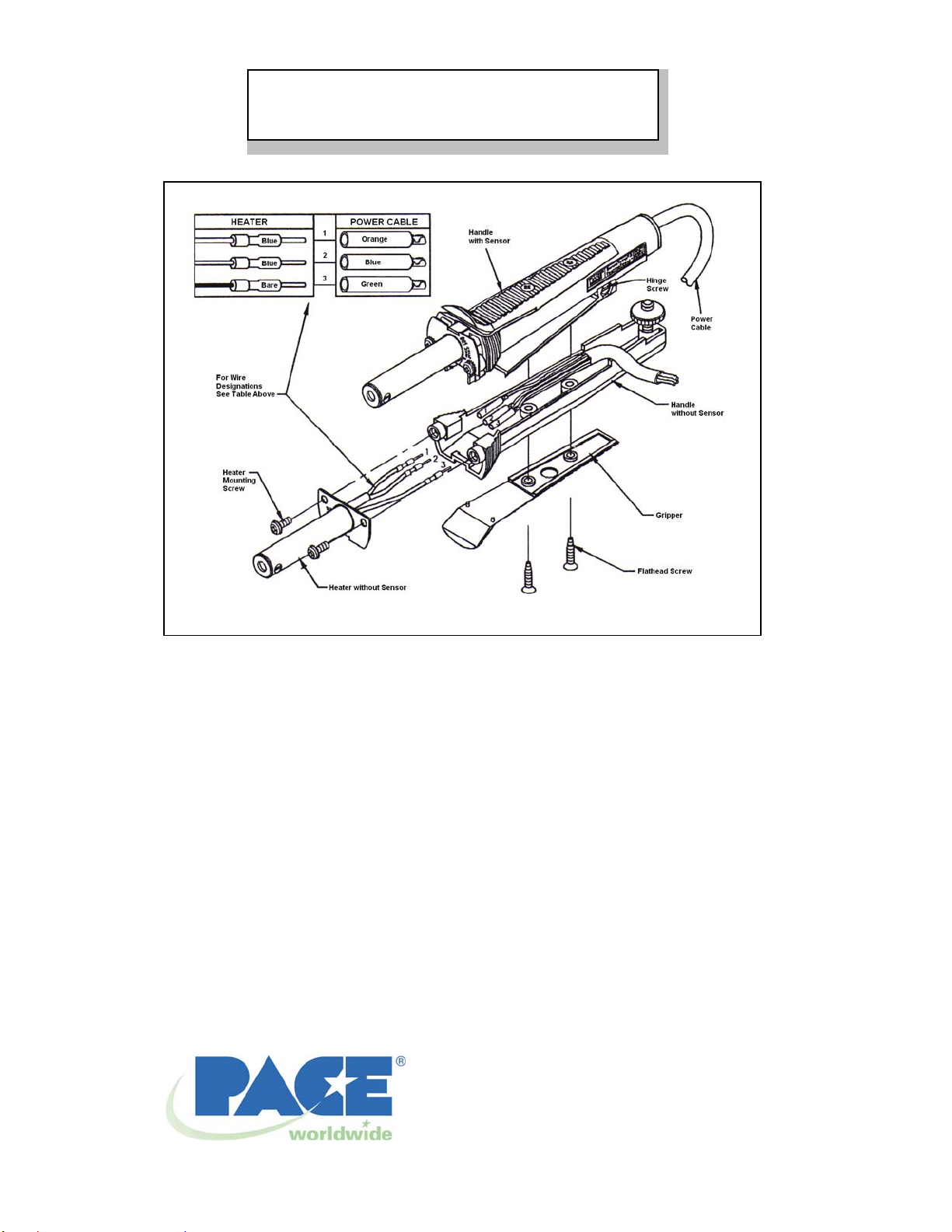
6. Carefully plug the three (3) color-coded leads of the replacement heater into the Power Cable leads as shown in
illustration.
a) Plug the Bare (non-insulated) heater lead into the Green Power Cable lead
b) Plug the two Blue heater leads into the Blue and the Orange Power Cable leads.
7. Mount the replacement heater to the handle using the two (2) Heater Mounting Screws removed in step 4.
8. Insure that the heater and Power Cable leads are dressed along the inside edges of the handle and not over the two
mounting shoulders in the handle center.
9. Carefully mate the two handpiece halves back together.
10. Install the Gripper and two (2) Gripper Mounting Screws removed in step 2.
11. Check the ends of both heaters to insure proper alignment with each other. If the end of one heater extends beyond the
other, loosen the Hinge Screw. Move the handles ba ck and forth to align ends of heate rs.
12. Tighten Hinge Screw to secure in positio n. Recheck the alignment.
13. Connect the handpiece to the system power source.
14. The handpiece is now ready for normal operation.
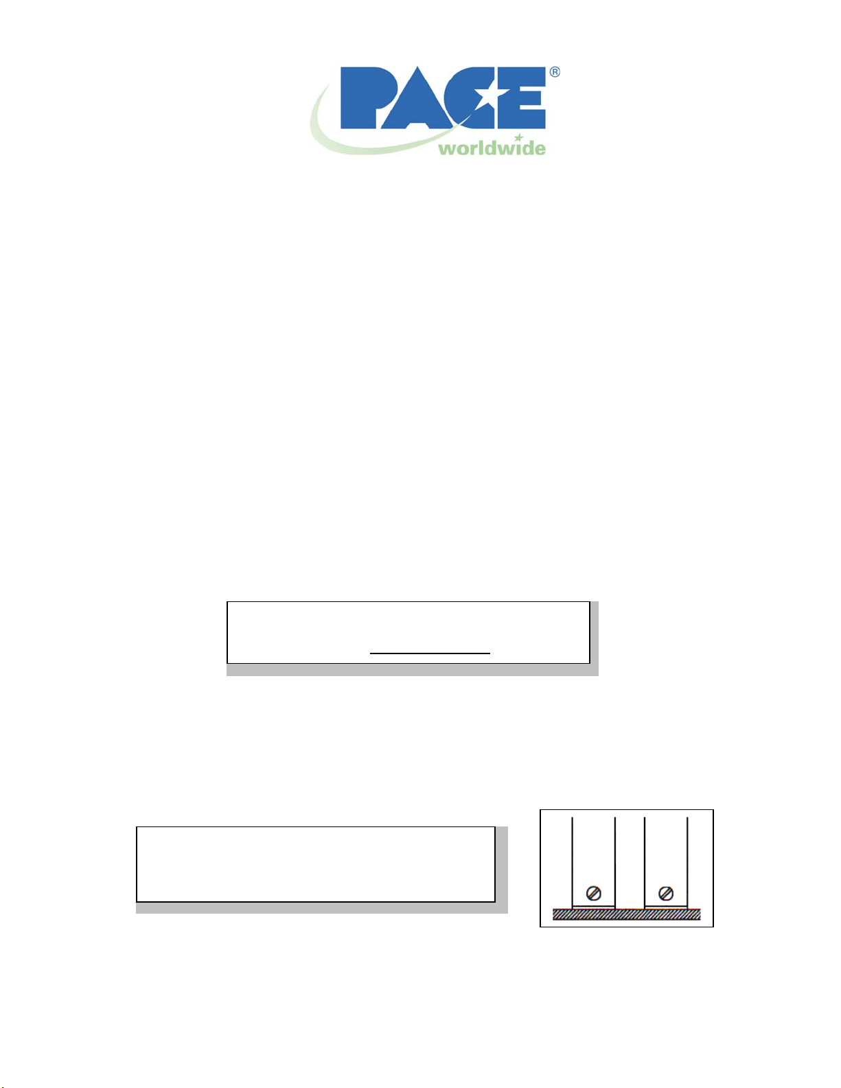
Placement of the heater ends against a flat work
surface with the handpiece held in a vertical position is
recommended to ease alignment.
TT-65 Heater Assembly (Assembly Without Sensor)
The tab of the heater flange must fit into the notch
located on the
NOTE
Operation Manual for the
PACE PART NUMBER 6010-0083-P1
MANUAL NUMBER 5050-0298 Rev. G
NOTE
outside edge of the handle.
Page 2
A
A small amount of smoke will be emitted for a period of
time when the heater is initially powered up.
NOTE
PACE Incorporated retains the right to make changes to specifications contained herein at any time, without notice.
Contact your local authorized PACE Distributor or PACE Incorporated to obtain the latest specifications.
The following are trademarks and/or service marks of PACE, Incorporated, MD, USA:
INSTACAL
POWERMODULE
The following are registered trademarks and/or service marks of PACE Incorporated, Annapolis Junction Maryland
U.S.A.
ARM-EVAC
SODR-X-TRACTOR
DRIVE
PACE products meet or exceed all applicable military and civilian EOS/ESD, temperature stability and other
specifications including MIL STD 2000, ANSI/JSTD 001, IPC7711, and IPC A-610.
™
, FUMEFLO™, HEATWISE™, PACEWORLDWIDE™, PERMAGROUND™, POWERPORT™,
™
, TEMPWISE™, TIP-BRITE™, AUTO-OFF™, and TEKLINK™.
®
, FLO-D-SODR®, MINIWAVE®, PACE®, SENSATEMP®, SNAP-VAC®, SODRTEK®,
®
, and TOOLNET®.
®
, THERMOFLO®, THERMOJET®, THERMOTWEEZ®, VISIFILTER®, THERMO-
PACE Incorporated
9030 Junction Drive
nnapolis Junction,
MD 20701
Tel: (301) 490-9860
Fax: (301) 498-3252
PACE Europe Limited
13 Tanners Drive
Blakelands
Milton Keynes
Tel: (44) 1908-277666
Fax: (44) 1908-277777
 Loading...