


06-14-07
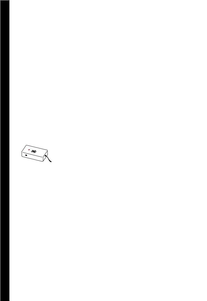
SWI-PS
Universal Steering Wheel Control Interface
with wired remote inputs. |
Installation Instructions |
For Pioneer and Sony Radios |
|
Pacific Accessory Corporation
Before You Start
A. Is this product compatible with the vehicle?
• See application guide (seperate sheet) for listing of vehicles and connection information. If not, check www.pacaudio.com for an updated list of compatible vehicles.
B. Prepare for the installation.
• If possible, install the SWI-PS while you are installing the new head unit. Keep in mind you may need to plug in the factory stereo to locate certain wires; therefore do not complete the head unit installation until the SWI-PS is working properly.
•Plan a general installation location for both the SWI-PS plug and the control body. Keep in mind that the supplied wire harness is two feet long, and the 1/8" plug harness is three feet long.
•Use a multimeter or approved measuring device for checking vehicle circuits.
|
|
IP-BUS cable |
|
SEEK |
VOLUME |
|
|
AM FM |
PLAY MUTE |
|
|
|
|
|
IP-BUS input |
|
Steering wheel |
Fuse |
Jack for the SWI-PS |
|
audio control wire |
||
Power |
|
Antenna jack |
|
|
|
|

Wiring Connections
Note: Only 3 wires will be used during installation. Only GM vehicles programmed for version #4, will use 4 wires.
Step 1.
Connect the BLACK wire to ground (-).
Verification: Wire or location registers a constant (-) when probed.
Step 2.
Connect the RED wire to switched +12V.
Verification: Wire registers +12V when the ignition key is turned to the ACC or ON posi-
tions.
Step 3.
Connect the appropriate interface wire (WHITE, YELLOW, ORANGE or GREEN).
• Refer to the Identification and Connection Chart. Locate the vehicle and note the SWC wire color in the “Interface Wire Color” column.
• Note the vehicle wire color and location information in the “Identification” column.
Note: You will only connect ONE of these wires. The other 3 wires will not be used. Cut and insulate the unused wires.
• Connect the wire as indicated in the chart.
Step 4
If necessary, perform the following operations as indicated by the notes in Identification and Connection Chart.
Note: Step 4a is for vehicles made by General Motors that are programmed for version #4 only. If no connections is necessary, proceed to Step 4b.
Step 4a.
Connect the BLUE serial data wire. Connect this wire
ONLY on GM passenger vehicles (no trucks or SUVs) with airbags AND steering wheel heater controls. For all other vehicles, cut and insulate the
BLUE wire.
Step 4b.
If instructed by the
Vehicle Application Guide, cut the BROWN wire loop and insulate both halves.
Step 4c.
If instructed by the Vehicle Application Guide, cut the VIOLET wire loop and insulate both halves, or place a resistor in-line of wires.
06-14-07
Programming the SWI-PS to Work With the Vehicle
Step 5.
Refer to The Vehicle Appication Guide. Note the INTERFACE Version Number next to the selected vehicle. Fill in the information below for quick reference.
Version Number: ____________
(Write Version Number here)
 SWI-PS
IGN
ACC
STRT
OFF
Step 6.
Press and hold programming/ mode button on SWI-PS. Turn the vehicle ignition to the ON position.
 SWI-PS
The LED on the SWI-PS will light.
SWI-PS |
Step 7. |
|
Release the programming/ |
|
mode button. |
SWI- |
Step 8. |
|
Press and release the program- |
||
PS |
||
|
||
|
ming/mode button the same |
|
|
number of times as the desired |
|
|
version number. |
SWI |
Step 9. |
|
After 3 seconds, the |
||
-PS |
||
|
LED will flash the same |
|
|
amount of times of set |
|
|
version number. |
SWI |
- |
The LED will turn off, |
|
||
|
indicating memory is |
|
|
PS |
|
|
|
cleared. |
SWI |
The LED will flash |
|
each time the button is |
||
- |
||
PS |
pressed and released. |
|
|
ACC |
|
|
Step 10. |
IGN |
|
Turn vehicle ignition |
|
|
|
STRT |
to OFF position. |
OFF |
|
|
Vehicle programming |
|
|
|
|
|
|
|
sequence is complete. |
 Loading...