

Page 1
OEM – 2
6
6
6
6
Universal sound system interface and controller
The OEM-2 may be used in any one of four possible confi gurations and system types.
1) Replacing a premium factory radio with an aftermarket stereo and use the factory amplifi er and speakers.
2) Four channel line out converter for adding amplifi ers to a standard factory speaker system.
3) Adding aftermarket amplifi ers to a factory premium amplifi ed system (Bose, JBL, etc.).
4) Installing a radio with fl oating ground speaker outputs to a common grounded speaker system like the early Fords.
The OEM-2 also includes a remote turn-on for amplifi ers or a power antenna, providing 2 amps at 12 volts when 0.8 volts or greater is applied to the input side. This
is useful for low voltage triggers like those used in Fords or for automatic triggering when audio is present. The output “turn on” is delayed 1 second to prevent turn
on pops.
Input wiring colors Output wiring colors
1
White
White/red
White/black
1
Gray
Gray/red
Gray/black
1
Green
Green/red
Green/black
1
Violet
Violet/red
Violet/black
4
Yellow
4
Red
4
Black
4
Blue
Blue/white
Orange
1
Connect these wires to an aftermarket radio (+) high power speaker output (typically 20 watts x 4 and higher).
2
Connect these wires to an aftermarket radio (+) low power speaker output. (All stereos up to 20 watts x 4 or when wiring for #4)
3
If the radio is high power (fl oating ground), connect these wires separately to each of the radio’s speaker (-) wire (do not connect (-) speaker wires together). If the
radio has a common ground speaker outputs, connect these wires together along with the radio’s speaker ground.
4
These wires go directly through to the outputs for convenience of wiring. The red and black wires supply power to the internal low voltage trigger.
5
This wire needs only a minimum of 0.8 volts to supply 12 volts on the blue/white wire on the output side of the OEM-2.
6
For convenience, the positive leads of the RCA are connected internally to these wires.
7
For convenience, the grounds of the RCA are connected internally to these wires. Not used with common grounded speakers.
4
LF (+) speaker (high power)
2
LF (+) speaker (low power) White/red LF (+) common gnd. speaker output
3
LF (–) common
RF (+) speaker (high power)
2
RF (+) speaker (low power) Gray/red RF (+) common gnd. speaker output
3
RF (–) common
LR (+) speaker (high power)
2
LR (+) speaker (low power) Green/red LR (+) common gnd. speaker output
3
LR (–) common
RR (+) speaker (high power)
2
RR (+) speaker (low power) Violet/red RR (+) common gnd. speaker output
3
RR (–) common
Constant battery Yellow Constant battery
Switched power Red Switched power
Gnd. neg. power Black Gnd. neg. power
Power antenna turn on Blue Power antenna turn on
5
Amplifier remote turn on 0.8 v min. Blue/white Amplifier remote turn on 2 amps max.
Illumination dimming Orange Illumination dimming
White
White/black
Gray
Gray/black
Green
Green/black
Violet
Violet/black
LF (+) low level output
7
LF (–) common
RF (+) low level output
7
RF (–) common
LR (+) low level output
7
LR (–) common
RR (+) low level output
7
RR (–) common
Note: Some Chrysler/Dodge vehicles with a Infi nity premium sound system do not need any interface. If the speakers fade and balance correctly with this interface
installed, but you have very little volume, then you do not need this interface.
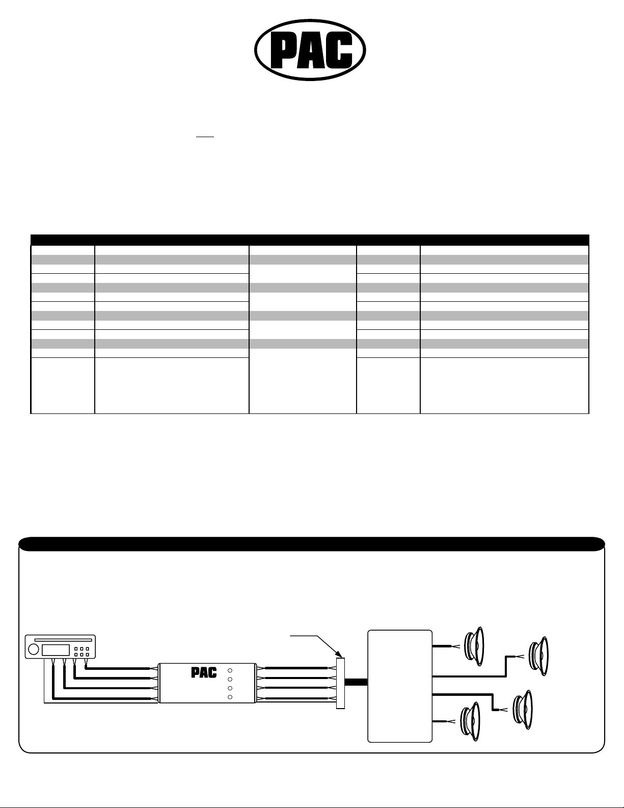
1) Replace the factory premium radio with an after market radio/deck and retain the use of the factory amplifi ers and speakers
Referring to the wire color chart above, connect the speaker outputs of the new radio to the OEM-2, using the positive, solid color, and the negative black-striped
wires for all four channels. On the output side of the OEM-2 connect the solid color wires (+) and the black-striped wires (-) to the factory harness leading to
the factory amplifi ers. If there are common audio return wires (-) used in the vehicle for either the front and rear channels then connect the negative outputs of
the OEM-2 to them. If there is only one audio return wire for all four channels connect all the black-striped wires to it. Connecting the constant power (yellow),
switched power (red), ground (black), antenna trigger (blue), illumination (orange), and amplifi er turn on (blue/white) through the OEM-2 simplifi es wiring to the
vehicle. The output level controls can be adjusted with a small screwdriver.
Aftermarket stereo
102.7 FM
connect blu/wht to new stereo's remote wire
rev. 10-7-02
plug removed from factory stereo
wht & wht/blk
gray & gray/blk
grn & grn/blk
vio & vio/blk
I
nput
PacificAccessory Corporation - Santa Ana, CA 92705
OEM-2
wht & wht/blk
gray & gray/blk
Output
grn&grn/blk
vio & vio/blk
blu/wht amplifier remote turn on
Factory Amplifier
Pacifi c Accessory Corporation - 1502 S. Santa Fe Street, Santa Ana, CA 92705
techsupport@go2pac.com • Voice: 714-835-3022 • Fax: 714-835-3233 • www.go2pac.com
LF
(+)
(-)
RF
(+)
(-)
LR
(+)
(-)
RR
(+)
(-)
Page 1
Page 2
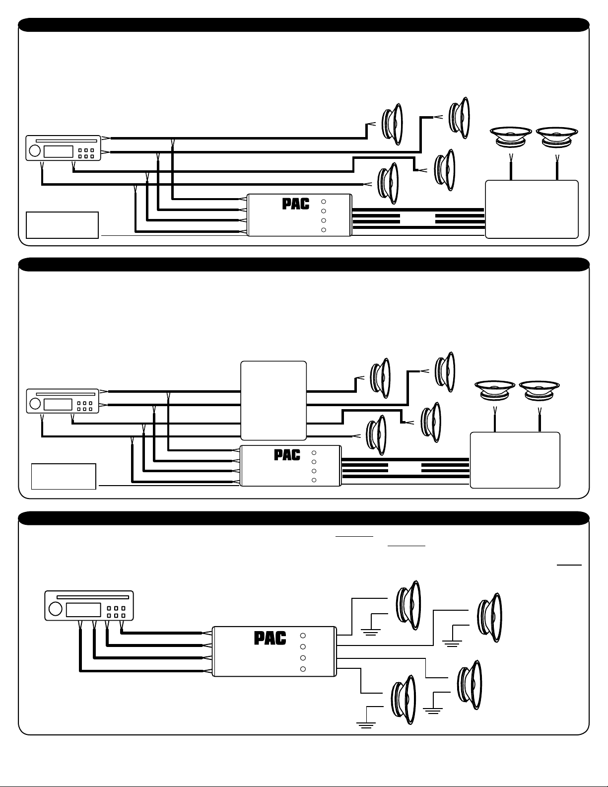
2) Adding an aftermarket amplifi er to a standard factory radio that does not have factory amplifi ers
The factory radio speaker outputs are connected to the OEM-2 inputs and the new amplifi er is connected to the output side of the OEM-2, using the four RCA
jacks and extension cables. Referring to the wire color chart, connect the factory radio speaker (+) outputs to the solid color wires and the (-) outputs to the
black-striped wires. Example, LF speaker outputs of the factory radio connect to the white wire (+) and white/black (-). Continue for the remaining channels. The
OEM-2 provides an amplifi er turn on signal. To use, connect the blue/white wire on the OEM-2 input side to one of the positive speaker wires or to any source
that provides 5 volts DC or greater. The blue/white wire on the output side will provide 12 volts to turn on the new amplifi er. Connect the red (+) and black (-) wires
on the input side to switched vehicle power and ground. Adjust the output level controls as needed using a small screwdriver.
LF
(+)
Factory stereo
(-)
LR
(+)
(-)
New subwoofers
102.7 FM
Connect blu/wht wire to any
speaker wire output of factory
radio (+ or -) for remote turn on
for new amplifier.
blu/wht
white & wht/blk
green & grn/blk
violet & vio/blk
gray & gray/blk
Input
PacificAccessory Corporation - Santa Ana, CA 92705
OEM-2
Output
RF
(+)
(-)
RCA out to
new amplifier
blu/wht 12 volt remote output
RR
(+)
(-)
(-)
(+)
New Amplifier
(-)
(+)
3) Adding after market amplifi ers to a factory premium amplifi ed system (Bose, JBL, etc.)
Referring to the wire color chart above, connect the audio output leads of the factory stereo to the input of the OEM-2, using the red striped wires as the positive
input and black-striped as negative. Most premium systems use a low -level signal from the stereo to the factory amplifi ers, therefore use the low level input of
the OEM-2. Some factory-amplifi ed systems use common audio returns and grounded shields like for instance, GM/Delco Bose vehicles. Do not cut the shield
wire or attempt to use it as an audio signal wire. Determine if your system has two common audio return wires, one for the front channels and a second for the
rear channels. If so, connect the negative input wires (black-stripe) for the front channels of the OEM-2 to the common audio return wire in the vehicle for the
front channels. Do the same for the rear channels. If the vehicle has only one audio return wire for all channels connect all of the black stripped wires to it. The
output level controls can be adjusted with a small screwdriver. Connect the red (+) and black (-) wires on the input side to switched vehicle power and ground.
LR
(+)
(-)
RR
(+)
(-)
New subwoofers
(-)
(+)
(-)
(+)
New Amplifier
Factory stereo
102.7 FM
Connect blu/wht wire to
factory amplifier remote turn
on. Example: some Fords
have a 5 volt remote turn on.
blu/wht
wht/red & wht/blk
grn/red & grn/blk
vio/red & vio/blk
gray/red & gray/blk
Factory amplifier
Input
PacificAccessory Corporation - Santa Ana, CA 92705
OEM-2
put
Out
LF
(+)
(-)
RF
(+)
(-)
RCA out to
new amplifier
blu/wht 12 volt remote output
4) Installing a radio with fl oating ground speaker outputs to a common grounded speaker system like the early Fords.
Referring to the wire color chart, connect the new stereo positive speaker outputs to the red striped wire on the input side of the OEM-2. Connect the negative
speaker outputs to the black-striped wires of the OEM-2. On the output side of the OEM-2 connect the red-striped wires to the vehicle positive speaker wiring.
The black striped wires on the output are not used. The negative side of each speaker is either common to each other on one wire or two in the factory plug or
already grounded to the chassis. However it may be, make sure that they are grounded to the vehicle chassis. The output level control on the OEM-2 will not
function in this confi guration.
Aftermarket stereo
102.7 FM
wht/red & wht/blk
gray/red & gray/blk
grn/red & grn/blk
vio/red & vio/blk
wht/red
Input
OEM-2
Output
PacificAccessory Corporation - Santa Ana, CA 92705
gry/red
LF
(+)
(-)
grn/red
LR
(+)
(-)
RR
RF
(+)
(-)
vio/red
(+)
(-)
Pacifi c Accessory Corporation - 1502 S. Santa Fe Street, Santa Ana, CA 92705
techsupport@go2pac.com • Voice: 714-835-3022 • Fax: 714-835-3233 • www.go2pac.com
Page 2
Page 3

Wiring the OEM-2 and aftermarket stereo to a GM
factory Bose Premium Sound System
Mobile Audio Interfacing Equipment
Important!
If you are using the supplied wire harness from Crutchfi eld, or other aftermarket wire harness either from Metra, Scosche or
American International, you can not connect the audio signal wires of the supplied wire harness to the OEM-2 color for color (you
may however, connect the red, black, blue, orange, and yellow wire color for color). The wire harness supplied by Crutchfi eld or other
above mentioned wire harnesses are not designed for Bose Premium Sound Systems. You will need to trace the factory wire colors
and match them over to the aftermarket harness. Connect the OEM-2 outputs according to the chart.
The factory wire colors given are typical of most GM vehicles with a Bose Premium Sound System. If the colors do not match up,
you will need to obtain a wiring diagram of your vehicle from a dealer. In some vehicles the audio common wires could have a striped
wire.
NOTES: 4 possible GM plug confi gurations.
GM21 and GM21A: has a bare shield wire for both front
a rear speakers.
GM21B: has no bare shield wire and has common wires
for front and rear.
GM21C: has a positive and negative wire for each
speaker.
Use the shield wire(s) as a guide to determine which
chart to use.
Factory plug.
Connect these wires to
1 = front audio shield, bare wire
2 = left front positive (LF+), tan
3 = right and left front common (-), lt. grn
4 = right front positive (RF+), dark green
5 = chassis ground, black
6 = illumination/dimmer, gray
7 = n/a
8 = remote turn on, pink
9 = 12 volt ignition/switched (+12), yellow
10 = 12 volt battery/constant (+12), orange
17 = rear audio shield, bare wire
18 = right rear positive (RR+), dark blue
19 = right and left rear common (-), yellow
20 = left rear positive (LR+), dark brown
Factory plug.
Connect these wires to
1 = left front positive (LF+), tan
2 = right and left front common (-), lt. grn
3 = right front positive (RF+), dark green
4 = front audio shield, bare wire
5 = chassis ground, black
6 = illumination/dimmer, gray
7 = n/a
8 = remote turn on, pink
9 = 12 volt ignition/switched (+12), yellow
10 = 12 volt battery/constant (+12), orange
17 = right rear positive (RR+), dark blue
18 = right and left rear common (-), yellow
19 = left rear positive (LR+), dark brown
20 = rear audio shield, bare wire
GM21
GM21A
OEM-2
black wire
wht wire
wht/blk and gry/blk wires
gry wire
black wire
orange wire
n/a
blue/wht
red wire
yellow wire
black wire
purple wire
prp/blk and grn/blk wires
grn wire
OEM-2
wht wire
wht/blk and gry/blk wires
gry wire
black wire
black wire
orange wire
n/a
blue/wht
red wire
yellow wire
purple wire
prp/blk and grn/blk wires
grn wire
black wire
12 13
11
234 567
1
14 15
16
17 18 19
20
89
10
Factory GM 21 pin plug
Viewed from pin side not wire side
Factory plug.
Connect these wires to
1 = n/a
2 = left front positive (LF+), tan
3 = n/a
4 = right front positive (RF+), dark green
5 = chassis ground, black
6 = illumination/dimmer, gray
7 = n/a
8 = remote turn on, pink
9 = 12 volt ignition/switched (+12), yellow
10 = 12 volt battery/constant (+12), orange
17 = audio common
18 = right rear positive (RR+), dark blue
19 = n/a
20 = left rear positive (LR+), dark brown
Factory plug.
Connect these wires to
1 = left front negative (LF-), gray
2 = left front positive (LF+), tan
3 = right front negative (RF-), dark green
4 = right front positive (RF+), lt. green
5 = chassis ground, black
6 = illumination/dimmer, gray
7=n/a
8 = remote turn on, pink
9 = 12 volt ignition/switched (+12), yellow
10 = 12 volt battery/constant (+12), orange
17 = right rear negative (RR-), lt. blue
18 = right rear positive (RR+), dark blue
19 = left rear negative (LR-), yellow
20 = left rear positive (LR+), brown
GM21B
GM21C
OEM-2
n/a
wht wire
n/a
gry wire
black wire
orange wire
n/a
blue/wht
red wire
yellow wire
prp/blk, wht/blk, gry/blk and grn/blk wires
purple wire
n/a
grn wire
OEM-2
wht/blk wire
wht wire
gry/blk wire
gry wire
black wire
orange wire
n/a
blue/wht
red wire
yellow wire
prp/blk wire
purple wire
grn/blk wire
grn wire
Document and Material Disclaimer: All information, including photos and illustrations, in these pages is believed to be correct and reliable. The information
contained in these pages is given as general information for the installation of audio accessories into mobile and/or vehicle applications. PACIFIC ACCESSORY
CORPORATION shall not be held liable for any damages and/or injuries resulting from the use of information contained in these pages. All information contained in
these pages should be checked and verifi ed with appropriate test equipment to assure the safety and proper operation of equipment installed and the vehicle itself.
Copyright © 2002 Pacifi c Accessory Corporation.
Pacifi c Accessory Corporation - 1502 S. Santa Fe Street, Santa Ana, CA 92705
11-08-02
techsupport@go2pac.com • Voice: 714-835-3022 • Fax: 714-835-3233 • www.go2pac.com
Page 1
Page 4

NOTES: 2 possible plug confi gurations.
GM32: has one audio shield wire.
GM32A: has two audio shield wires.
Use the shield wire(s) as a reference to
select which chart to use.
2E1
3456
2F1
3456
789101112131415 16
789101112131415 16
Factory GM 32 pin plug
Viewed from pin side not wire side
Factory plug.
Connect these wires to
1=n/a
2=n/a
3 = remote turn on
4=n/a
5=n/a
6=n/a
7=n/a
8=n/a
9=n/a
10 = n/a
12 = left rear positive (LR+)
13 = n/a
14 = n/a
15 = right rear positive (RR+)
16 = chassis ground
1 = constant 12 volts
2 = accessory 12 volts
3=antennaremoteturnon
4 = illumination/dimmer
5=n/a
6=n/a
7=n/a
8=n/a
9=n/a
10 = n/a
12 = left front positive (LF+)
13 = audio shield, bare wire
14 = audio common return (-)
15 = right front positive (RF+)
16 = n/a
Row E
Row F
GM32
OEM-2
n/a
n/a
blue/wht wire
n/a
n/a
n/a
n/a
n/a
n/a
n/a
grn wire
n/a
n/a
prp wire
black wire
yellow wire
red wire
blue wire
orange
n/a
n/a
n/a
n/a
n/a
n/a
wht wire
black wire
prp/blk,grn/blk,gry/blk and wht/blk wires
gry wire
n/a
Factory plug.
Connect these wires to
1=n/a
2=n/a
3 = remote turn on
4=n/a
5=n/a
6=n/a
7=n/a
8=n/a
9=n/a
10 = n/a
12 = left rear positive (LR+)
13 = rear audio shield, bare wire
14 = rear audio common return (-)
15 = right rear positive (RR+)
16 = chassis ground
1 = constant 12 volts
2 = accessory 12 volts
3 = antenna remote turn on
4 = illumination/dimmer
5=n/a
6=n/a
7=n/a
8=n/a
9=n/a
10=n/a
12 = left front positive (LF+)
13 = front audio shield, bare wire
14 = front audio common return (-)
15 = right front positive (RF+)
16=n/a
Row E
Row F
GM32A
OEM-2
n/a
n/a
blue/wht wire
n/a
n/a
n/a
n/a
n/a
n/a
n/a
grn wire
black wire
prp/blk and grn/blk wire
prp wire
black wire
yellow wire
red wire
blue wire
orange
n/a
n/a
n/a
n/a
n/a
n/a
wht wire
black wire
gry/blk and wht/blk wires
gry wire
n/a
G
M
BLACK
A
B
WHITE
H
J
BLUE
F
E
C
D
K
L
Factory plug.
Connect these wires to
A = right front positive (RF+), lt. grn
B = left front positive (LF+), tan
C = front shield, bare wire
D = right front negative, left front negative
E = remote turn on, pink
F = 12 volt ignition/switched (+12), yellow
G = ground, black
H = left rear positive (LR+), brown
J = right rear positive (RR+), dark blue
K = left rear negative, right rear negative
L = rear shield, bare wire
M = illumination/dimmer, gray
on separate two pin, white plug, orange
wire is constant 12 volts.
Late 1984 and later models only
GM12
OEM-2
gry wire
wht wire
black wire
gry/blk and wht/blk wire
blue/wht wire
red wire
black wire
green wire
prp wire
prp/blk and grn/blk wire
black wire
orange wire
yellow wire
Viewed from pin side not wire side
Pacifi c Accessory Corporation - 1502 S. Santa Fe Street, Santa Ana, CA 92705
techsupport@go2pac.com • Voice: 714-835-3022 • Fax: 714-835-3233 • www.go2pac.com
Page 2
 Loading...